RU2583813C2 - Disinfecting device using ozone and flow sensor therefor - Google Patents
Disinfecting device using ozone and flow sensor therefor Download PDFInfo
- Publication number
- RU2583813C2 RU2583813C2 RU2013154980/05A RU2013154980A RU2583813C2 RU 2583813 C2 RU2583813 C2 RU 2583813C2 RU 2013154980/05 A RU2013154980/05 A RU 2013154980/05A RU 2013154980 A RU2013154980 A RU 2013154980A RU 2583813 C2 RU2583813 C2 RU 2583813C2
- Authority
- RU
- Russia
- Prior art keywords
- ozone
- water
- mixer
- disinfecting device
- inlet
- Prior art date
Links
Images

Classifications
-
- A—HUMAN NECESSITIES
- A23—FOODS OR FOODSTUFFS; TREATMENT THEREOF, NOT COVERED BY OTHER CLASSES
- A23L—FOODS, FOODSTUFFS, OR NON-ALCOHOLIC BEVERAGES, NOT COVERED BY SUBCLASSES A21D OR A23B-A23J; THEIR PREPARATION OR TREATMENT, e.g. COOKING, MODIFICATION OF NUTRITIVE QUALITIES, PHYSICAL TREATMENT; PRESERVATION OF FOODS OR FOODSTUFFS, IN GENERAL
- A23L3/00—Preservation of foods or foodstuffs, in general, e.g. pasteurising, sterilising, specially adapted for foods or foodstuffs
- A23L3/34—Preservation of foods or foodstuffs, in general, e.g. pasteurising, sterilising, specially adapted for foods or foodstuffs by treatment with chemicals
- A23L3/3409—Preservation of foods or foodstuffs, in general, e.g. pasteurising, sterilising, specially adapted for foods or foodstuffs by treatment with chemicals in the form of gases, e.g. fumigation; Compositions or apparatus therefor
-
- A—HUMAN NECESSITIES
- A23—FOODS OR FOODSTUFFS; TREATMENT THEREOF, NOT COVERED BY OTHER CLASSES
- A23L—FOODS, FOODSTUFFS, OR NON-ALCOHOLIC BEVERAGES, NOT COVERED BY SUBCLASSES A21D OR A23B-A23J; THEIR PREPARATION OR TREATMENT, e.g. COOKING, MODIFICATION OF NUTRITIVE QUALITIES, PHYSICAL TREATMENT; PRESERVATION OF FOODS OR FOODSTUFFS, IN GENERAL
- A23L3/00—Preservation of foods or foodstuffs, in general, e.g. pasteurising, sterilising, specially adapted for foods or foodstuffs
- A23L3/003—Control or safety devices for sterilisation or pasteurisation systems
-
- A—HUMAN NECESSITIES
- A23—FOODS OR FOODSTUFFS; TREATMENT THEREOF, NOT COVERED BY OTHER CLASSES
- A23L—FOODS, FOODSTUFFS, OR NON-ALCOHOLIC BEVERAGES, NOT COVERED BY SUBCLASSES A21D OR A23B-A23J; THEIR PREPARATION OR TREATMENT, e.g. COOKING, MODIFICATION OF NUTRITIVE QUALITIES, PHYSICAL TREATMENT; PRESERVATION OF FOODS OR FOODSTUFFS, IN GENERAL
- A23L3/00—Preservation of foods or foodstuffs, in general, e.g. pasteurising, sterilising, specially adapted for foods or foodstuffs
- A23L3/34—Preservation of foods or foodstuffs, in general, e.g. pasteurising, sterilising, specially adapted for foods or foodstuffs by treatment with chemicals
- A23L3/3454—Preservation of foods or foodstuffs, in general, e.g. pasteurising, sterilising, specially adapted for foods or foodstuffs by treatment with chemicals in the form of liquids or solids
- A23L3/3589—Apparatus for preserving using liquids
-
- A—HUMAN NECESSITIES
- A61—MEDICAL OR VETERINARY SCIENCE; HYGIENE
- A61L—METHODS OR APPARATUS FOR STERILISING MATERIALS OR OBJECTS IN GENERAL; DISINFECTION, STERILISATION OR DEODORISATION OF AIR; CHEMICAL ASPECTS OF BANDAGES, DRESSINGS, ABSORBENT PADS OR SURGICAL ARTICLES; MATERIALS FOR BANDAGES, DRESSINGS, ABSORBENT PADS OR SURGICAL ARTICLES
- A61L2/00—Methods or apparatus for disinfecting or sterilising materials or objects other than foodstuffs or contact lenses; Accessories therefor
- A61L2/16—Methods or apparatus for disinfecting or sterilising materials or objects other than foodstuffs or contact lenses; Accessories therefor using chemical substances
- A61L2/18—Liquid substances or solutions comprising solids or dissolved gases
- A61L2/183—Ozone dissolved in a liquid
-
- C—CHEMISTRY; METALLURGY
- C02—TREATMENT OF WATER, WASTE WATER, SEWAGE, OR SLUDGE
- C02F—TREATMENT OF WATER, WASTE WATER, SEWAGE, OR SLUDGE
- C02F1/00—Treatment of water, waste water, or sewage
- C02F1/72—Treatment of water, waste water, or sewage by oxidation
- C02F1/78—Treatment of water, waste water, or sewage by oxidation with ozone
-
- C—CHEMISTRY; METALLURGY
- C02—TREATMENT OF WATER, WASTE WATER, SEWAGE, OR SLUDGE
- C02F—TREATMENT OF WATER, WASTE WATER, SEWAGE, OR SLUDGE
- C02F1/00—Treatment of water, waste water, or sewage
- C02F1/008—Control or steering systems not provided for elsewhere in subclass C02F
-
- C—CHEMISTRY; METALLURGY
- C02—TREATMENT OF WATER, WASTE WATER, SEWAGE, OR SLUDGE
- C02F—TREATMENT OF WATER, WASTE WATER, SEWAGE, OR SLUDGE
- C02F2209/00—Controlling or monitoring parameters in water treatment
- C02F2209/40—Liquid flow rate
-
- C—CHEMISTRY; METALLURGY
- C02—TREATMENT OF WATER, WASTE WATER, SEWAGE, OR SLUDGE
- C02F—TREATMENT OF WATER, WASTE WATER, SEWAGE, OR SLUDGE
- C02F2303/00—Specific treatment goals
- C02F2303/04—Disinfection
-
- C—CHEMISTRY; METALLURGY
- C02—TREATMENT OF WATER, WASTE WATER, SEWAGE, OR SLUDGE
- C02F—TREATMENT OF WATER, WASTE WATER, SEWAGE, OR SLUDGE
- C02F2307/00—Location of water treatment or water treatment device
- C02F2307/06—Mounted on or being part of a faucet, shower handle or showerhead
Abstract
Description
ОБЛАСТЬ ТЕХНИКИFIELD OF TECHNOLOGY
Настоящее изобретение относится к дезинфицирующему устройству общего характера с использованием озона, причем устройство при использовании распыляет воду с эффективным и подходящим количеством озона в ней. Более конкретно, изобретение относится к дезинфицирующему устройству с использованием озона, которое подходит для обработки пищи, хотя может быть применено и в других областях.The present invention relates to a general disinfecting device using ozone, the device spraying water with an effective and suitable amount of ozone in use. More specifically, the invention relates to a disinfecting device using ozone, which is suitable for food processing, although it can be applied in other areas.
Еще более конкретно, изобретение относится к дезинфицирующему устройству общего характера, описанному в нашей ранее опубликованной международной патентной заявке WO 2010/001279.Even more specifically, the invention relates to a general disinfecting device described in our previously published international patent application WO 2010/001279.
ПРЕДПОСЫЛКИ ДЛЯ СОЗДАНИЯ ИЗОБРЕТЕНИЯBACKGROUND OF THE INVENTION
Рост микробов является одной из главных проблем в пищевой промышленности и у потребителей. Присутствие патогенных микроорганизмов на пищевых продуктах потенциально может приводить к пищевым заболеваниям.The growth of microbes is one of the main problems in the food industry and among consumers. The presence of pathogenic microorganisms in food can potentially lead to foodborne diseases.
Химикаты на основе хлора, такие как гипохлорит натрия, гипохлорит кальция, дихлоризоцианурат натрия и соединения четвертичного аммония, применялись для дезинфекции пищевых продуктов в прошлом. Однако хлор наиболее эффективен при 6-8 и становится менее эффективен за пределами этого диапазона pH. Также хлор может продуцировать токсичные побочные продукты, которые вредны для здоровья человека, такие как хлорамины и тригалометаны.Chlorine-based chemicals such as sodium hypochlorite, calcium hypochlorite, sodium dichloroisocyanurate and quaternary ammonium compounds have been used in the past to disinfect food products. However, chlorine is most effective at 6–8 and becomes less effective beyond this pH range. Chlorine can also produce toxic by-products that are harmful to human health, such as chloramines and trihalomethanes.
В результате этого Европейский Союз ввел запрет на использование соединений хлора для дезинфекции пищевой продукции своей Директивой EU 2092/91. Она, следовательно, является совместным усилием по улучшению технологии применения продуктов на основе хлора для обработки пищевых продуктов с целью их дезинфекции. Это привело к повышению интереса к дезинфицирующим свойствам озона. Использование озона для дезинфекции пищи было одобрено Управлением по санитарному надзору за качеством пищевых продуктов и медикаментов (FDA).As a result, the European Union has banned the use of chlorine compounds for the disinfection of food products by its EU Directive 2092/91. Therefore, it is a joint effort to improve the technology of using chlorine-based products for food processing with the aim of disinfection. This has led to increased interest in the disinfecting properties of ozone. The use of ozone for food disinfection has been approved by the Food and Drug Administration (FDA).
Отмечается, что, согласно сообщениям, окислительный потенциал озона приблизительно в 1,5 раза больше чем у хлора, причем время контакта для противомикробного действия озона обычно в четыре-пять раз меньше, чем у хлора.It is noted that, according to reports, the oxidative potential of ozone is approximately 1.5 times greater than that of chlorine, and the contact time for the antimicrobial action of ozone is usually four to five times less than that of chlorine.
Доказано, что озон является высоко реактивным окислителем, который способен убивать микроорганизмы, такие как бактерии, а также реагировать с другими химикатами, такими как пестициды и гербициды. Конечно, одним из главных преимуществ озона является его естественное разложение в кислород, и таким образом его использование для дезинфекции пищевых продуктов является очень выгодным, поскольку он разлагается в нетоксичный газ. Поэтому он не придает запаха или окраски пищевым продуктам и не оставляет остаточных соединений или токсичного остатка. Промывная вода может быть сброшена в окружающую среду или использована для других целей без дополнительной обработки или обеззараживания.It has been proven that ozone is a highly reactive oxidizing agent that can kill microorganisms such as bacteria and also react with other chemicals such as pesticides and herbicides. Of course, one of the main advantages of ozone is its natural decomposition into oxygen, and thus its use for the disinfection of food products is very beneficial because it decomposes into a non-toxic gas. Therefore, it does not give a smell or coloring to food products and does not leave residual compounds or a toxic residue. Wash water can be discharged into the environment or used for other purposes without additional treatment or disinfection.
Способы дезинфекции, известные заявителю из уровня техники, в которых применены озон, инжекторные системы Вентури и барботажные диффузоры, используют для смешивания озона с водой. В случае инжекторов Вентури вода продавливается через суживающее коническое тело, создавая разницу давлений на входе и выходе системы. Это создает вакуум внутри корпуса инжектора, инициируя поток обогащенного озоном воздуха в канале всасывания.Disinfection methods known to the applicant of the prior art in which ozone, Venturi injection systems and bubble diffusers are used are used to mix ozone with water. In the case of Venturi injectors, water is forced through a narrowing conical body, creating a pressure difference at the inlet and outlet of the system. This creates a vacuum inside the injector body, initiating the flow of ozone-enriched air in the suction channel.
Что касается барботажных диффузоров, обогащенный озоном воздух выходит пузырями ниже поверхности воды. Независимо от проблем, описанных ниже, барботажные диффузоры имеют неотъемлемый недостаток в том, что отверстия диффузора с течением времени часто забиваются, этим снижая КПД системы.As for bubble diffusers, ozone-enriched air escapes in bubbles below the surface of the water. Regardless of the problems described below, bubbled diffusers have an inherent disadvantage in that the diffuser openings often clog over time, thereby reducing system efficiency.
В обоих случаях озон растворяется в воде, обычно из обогащенного озоном воздуха, и существенная часть стерилизующей способности озона может быть затрачена на стерилизацию самой воды. Это оставляет уменьшенное количество озона для эффективной дезинфекции конечной цели, которой может быть, например, свежая продукция.In both cases, ozone dissolves in water, usually from air enriched with ozone, and a substantial part of the sterilizing ability of ozone can be spent on sterilizing the water itself. This leaves a reduced amount of ozone for effective disinfection of the final goal, which may be, for example, fresh produce.
Кроме того, эти известные системы, кажется, позволяют свободному газообразному озону выходить в атмосферу в более высоких концентрациях, чем разрешено регулирующими стандартами. Следует сказать, что свободный озон в воздухе вреден, когда он превышает определенные концентрации.In addition, these well-known systems seem to allow free gaseous ozone to escape into the atmosphere at higher concentrations than permitted by regulatory standards. It should be said that free ozone in the air is harmful when it exceeds certain concentrations.
В этой связи следует сказать, что в Европейском Союзе текущее целевое значение концентраций озона, по сообщениям, составляет 120 мкг/м3, что равно приблизительно 60 нмоль/моль. Это значение применимо во всех государствах-участниках в соответствии с Директивой 2008/50/ЕС, хотя для формального применения этого значения в качестве требования даты еще не установлено, и оно рассматривается как цель в длительной перспективе. В США в мае 2008 года Управление по охране окружающей среды (ЕРА) снизило свой стандарт на озон с 80 нмоль/моль до 75 нмоль/моль. Это было сделано несмотря на тот факт, что научные работники и консультативный совет самого Управления рекомендовали снизить стандарт до 60 нмоль/моль. ЕРА разработало Индекс качества воздуха, чтобы помочь разъяснить обществу уровни загрязнения воздуха, и в настоящее время действующие стандарты указывают среднюю за восемь часов молярную долю озона 85-104 нмоль/моль как "нездоровую для чувствительных групп"; 105 нмоль/моль - 124 нмоль/моль как "нездоровую" и 125 нмоль/моль - 404 нмоль/моль как "очень нездоровую". Рекомендация Всемирной организации здравоохранения составляет 51 нмоль/моль.In this regard, it should be said that in the European Union, the current target value of ozone concentrations is reported to be 120 μg / m 3 , which is approximately 60 nmol / mol. This value is applicable in all member states in accordance with Directive 2008/50 / EC, although for the formal application of this value as a requirement for a date has not yet been set, and it is considered as a goal in the long term. In May 2008, the United States Environmental Protection Agency (EPA) lowered its ozone standard from 80 nmol / mol to 75 nmol / mol. This was done despite the fact that scientists and the advisory board of the Office itself recommended lowering the standard to 60 nmol / mol. EPA has developed an Air Quality Index to help educate the public about air pollution levels, and current standards indicate an average of eight-hour average molar fraction of ozone 85-104 nmol / mol as “unhealthy for sensitive groups”; 105 nmol / mol - 124 nmol / mol as "unhealthy" and 125 nmol / mol - 404 nmol / mol as "very unhealthy". The recommendation of the World Health Organization is 51 nmol / mol.
Излишек озона в воздухе поэтому очень нежелателен, и важно, чтобы любое дезинфицирующее устройство, использующее озон в качестве активной дезинфицирующей среды, не должно выбрасывать существенные количества озона в атмосферу, при этом создавая эффективную концентрацию для разрушения целевых бактерий и т.д.Excess ozone in the air is therefore very undesirable, and it is important that any disinfecting device that uses ozone as an active disinfecting medium should not emit significant amounts of ozone into the atmosphere, while creating an effective concentration to destroy the target bacteria, etc.
В нашей вышеуказанной международной патентной заявке, которая подана раньше, предложение по отслеживанию потока воды через смеситель заключалось в контроле роста давления в смесителе, когда вода подается в смеситель под давлением. Это не всегда работает эффективно, и необходимо исследовать альтернативные средства управления.In our previously mentioned international patent application, the proposal to monitor the flow of water through the mixer was to control the pressure increase in the mixer when water is supplied to the mixer under pressure. This does not always work efficiently, and alternative controls need to be explored.
РАСКРЫТИЕ ИЗОБРЕТЕНИЯSUMMARY OF THE INVENTION
В соответствии с настоящим изобретением, предлагается дезинфицирующее устройство с использованием озона, включающее смеситель, имеющий в общем полый корпус с входом для воды под давлением, распылительную форсунку для создания в общем конического факела распыла воды, введенной через вход для воды, камеру контакта, сообщающуюся с входом для газов, обогащенных озоном, выходное отверстие камеры контакта, причем выходное отверстие соосно распылительной форсунке и отнесено от нее на некоторое расстояние, и устройство отслеживания расхода для отслеживания расхода воды через распылительную форсунку, причем дезинфицирующее устройство с использованием озона отличается тем, что устройство отслеживания расхода является электронным устройством отслеживания расхода для отслеживания вибрации, вызываемой потоком воды через смеситель.In accordance with the present invention, there is provided a disinfecting device using ozone, comprising a mixer having a generally hollow body with a pressurized water inlet, a spray nozzle for creating a generally conical spray of water introduced through the water inlet, a contact chamber in communication with the entrance for gases enriched with ozone, the outlet of the contact chamber, and the outlet is coaxial to the spray nozzle and spaced a certain distance from it, and a flow monitoring device for I monitor the flow rate of water through the spray nozzle, the ozone disinfecting device being characterized in that the flow monitoring device is an electronic flow monitoring device for monitoring vibration caused by the flow of water through the mixer.
Другие признаки изобретения предусматривают следующее: электронное устройство отслеживания расхода расположено в кармане, выполненном в корпусе смесителя, электронное устройство отслеживания расхода включает пьезоэлектрический датчик и соответствующую связанную с ним схему генерации сигнала, указывающего расход воды через смеситель, пьезоэлектрический датчик введен в затвердевающий материал и имеет общую форму диска с тонким сжимаемым диском меньшего диаметра, прикрепленным концентрически к обеим поверхностям диска датчика, причем наружный диаметр пьезоэлектрического датчика плотно введен в затвердевающий материал, и причем небольшое отверстие в центре одного диска обеспечивает контакт затвердевающего материала с пьезоэлектрическим датчиком в центральной области на одной его стороне.Other features of the invention include the following: an electronic flow monitoring device is located in a pocket made in the mixer body, an electronic flow monitoring device includes a piezoelectric sensor and a corresponding signal generating circuit indicating the flow rate of water through the mixer, the piezoelectric sensor is introduced into the hardening material and has a common a disk shape with a thin compressible disk of a smaller diameter attached concentrically to both surfaces of the sensor disk, with cm outer diameter of the piezoelectric transducer tightly introduced in the solidifying material, and wherein a small hole in the center of the disk ensures contact of the solidifying material to the piezoelectric sensor in the central region on one side thereof.
Другие признаки изобретения предусматривают, что связанная схема расположена на печатной плате, размещенной в корпусе смесителя, причем печатная плата размещена в кармане корпуса смесителя, устройство отслеживания расхода и связанная схема предназначены для включения и отключения генератора озона, оперативно соединенного с входом для газов, обогащенных озоном, устройство отслеживания расхода и связанная схема выводят сигнал, чтобы оперативно включать и отключать вентилятор, подающий воздух в генератор озона, причем включение вентилятора происходит до включения генератора озона и отключение вентилятора происходит после отключения генератора озона, и что вентилятор способен работать с разными частотами вращения в зависимости от расхода воды через распылительную форсунку.Other features of the invention provide that the associated circuit is located on a printed circuit board located in the mixer housing, the printed circuit board being located in the pocket of the mixer housing, the flow monitoring device and the associated circuit are designed to turn on and off an ozone generator operatively connected to an input for ozone-rich gases , the flow tracking device and the associated circuit output a signal to quickly turn on and off the fan supplying air to the ozone generator, and turning on the valve torus occurs before turning the fan and ozone generator shutdown occurs after disconnection of the ozone generator, and that the fan is able to work with different rotational speeds depending on the water flow through the spray nozzle.
Дополнительные признаки изобретения предусматривают, что диаметр выходного отверстия по существу соответствует диаметру конического факела распыла в таком положении, что при использовании по существу не остается свободного пространства между наружной границей факела распыла и периметром выходного отверстия, что сама камера контакта имеет размер поперечного сечения больше диаметра выходного отверстия, и что вход для газов, обогащенных озоном, имеет ось, параллельную оси входа для воды, но смещенную вбок от нее, причем камера входа газа сливается сбоку с камерой контакта.Additional features of the invention provide that the diameter of the outlet substantially corresponds to the diameter of the conical spray pattern in such a position that, when used, there is essentially no free space between the outer boundary of the spray pattern and the perimeter of the outlet, so that the contact chamber itself has a cross-sectional dimension larger than the diameter of the outlet holes, and that the inlet for gases enriched in ozone has an axis parallel to the axis of the inlet for water, but offset laterally from it, and the gas inlet chamber merges laterally with the contact cam.
Корпус смесителя предпочтительно состоит из первой части в форме колпака, определяющей выходное отверстие, который соединен на открытом конце напротив выходного отверстия со второй частью, определяющей вход для воды, вход для газа и карман для приема электронного устройства отслеживания расхода для отслеживания расхода воды через распылительную форсунку, причем вторая часть корпуса подсоединена на открытом конце колпака как вставка.The mixer housing preferably consists of a first part in the form of a cap defining an outlet, which is connected at the open end opposite the outlet with a second part defining an inlet for water, a gas inlet and a pocket for receiving an electronic flow monitoring device for monitoring the flow of water through the spray nozzle moreover, the second part of the housing is connected at the open end of the cap as an insert.
Вход для воды предпочтительно выполнен как гнездо с винтовой резьбой для прямого соединения с насадкой с соответствующей резьбой на кран или другое устройство подачи воды по трубам.The water inlet is preferably configured as a screw-threaded socket for direct connection to a nozzle with a corresponding thread on a faucet or other water supply device through pipes.
В соответствии со вторым аспектом изобретения предложено дезинфицирующее устройство с использованием озона, включающее описанный выше смеситель, генератор озона, оперативно соединенный с входом для газов, обогащенных озоном, в смесителе, и схему управления, соединенную с устройством отслеживания расхода и связанной схемой, причем схема управления предназначена для включения генератора озона после приема сигнала от устройства отслеживания расхода и связанной с ним схемы, когда данный сигнал соответствует минимальному расходу воды через смеситель, который требуется для создания подходящего факела распыла воды, поступающей в выходное отверстие из камеры контакта, и для отключения генератора озона, если принятый сигнал соответствует меньшему расходу, чем упомянутый минимальный расход.In accordance with a second aspect of the invention, there is provided a disinfecting device using ozone, comprising a mixer as described above, an ozone generator operatively connected to an input for ozone-enriched gases in a mixer, and a control circuit connected to a flow monitoring device and a related circuit, the control circuit being It is designed to turn on the ozone generator after receiving a signal from the flow monitoring device and the associated circuit, when this signal corresponds to the minimum flow rate of water. es mixer which is required to produce a suitable spray pattern of water entering the outlet of the contact chamber, and to turn off the ozone generator, if the received signal corresponds to a smaller flow rate than said minimum flow rate.
Следует сказать, что осуществление настоящего изобретения на практике приводит к захвату газов, обогащенных озоном, многочисленными каплями воды в спрее, и считается, что озон сам присоединяется, возможно электромагнитным или электростатическим способом, к поверхности капель воды без растворения какой-либо существенной части озона в воде. Эта теория объясняет практические измерения, выполненные до настоящего времени, которые указывают, что вода несет больше озона, чем могло бы в ней раствориться в нормальных условиях. Испытания, проведенные до настоящего времени, также показали, что в воздухе, окружающем факел распыла дезинфицирующего средства, свободного озона, по существу, нет, и в израсходованной воде озон присутствует в небольшом количестве или отсутствует вообще. Практическое осуществления изобретения явно приближается к оптимальному использованию озона и позволяет ему быть высокоэффективным при дезинфекции.It should be said that the practice of the present invention entails the capture of gases enriched in ozone with numerous drops of water in the spray, and it is believed that ozone itself attaches, possibly by electromagnetic or electrostatic means, to the surface of water drops without dissolving any significant part of the ozone in water. This theory explains the practical measurements made to date, which indicate that water carries more ozone than it could dissolve in it under normal conditions. Tests conducted to date have also shown that there is essentially no free ozone in the air surrounding the disinfectant spray torch, and that there is little or no ozone in the consumed water. The practical implementation of the invention is clearly approaching the optimal use of ozone and allows it to be highly effective in disinfection.
Хотя механизм прикрепления или другого притяжения молекул озона к каплям воды еще не полностью понят или не полностью исследован с технической точки зрения, испытания, проведенные до настоящего времени, показывают, что размер капли в спрее предпочтительно составляет от 10 до 50 мкм, и конус факела распыла имеет угол от 35° до 45°. Также поток, развиваемый вентилятором, и уменьшение давления, создаваемого потоком конического факела распыла в выходном отверстии, такое, что в камере контакта поддерживается слабо отрицательное давление порядка 10 мм вод.ст. (100 Па). В этой связи дальнейшие испытания будут направлены на установление того, практично ли или нет полностью отказаться от вентилятора, и это будет в большой степени зависеть от отрицательного давления, которое создается в камере контакта, и характера пути потока через генератор озона в смеситель.Although the mechanism of attachment or other attraction of ozone molecules to water droplets is not yet fully understood or has not been fully studied from a technical point of view, tests carried out to date have shown that the droplet size in the spray is preferably from 10 to 50 microns, and the spray cone has an angle of 35 ° to 45 °. Also, the flow developed by the fan and the decrease in pressure generated by the conical spray jet in the outlet are such that a slightly negative pressure of about 10 mm water column is maintained in the contact chamber. (100 Pa). In this regard, further tests will be aimed at establishing whether or not it is practical to completely abandon the fan, and this will largely depend on the negative pressure created in the contact chamber and the nature of the flow path through the ozone generator to the mixer.
Для того чтобы вышеописанные и другие признаки изобретения стали более очевидными, теперь будет описан один вариант осуществления, включающий все разные аспекты изобретения, со ссылками на прилагаемые чертежи.In order for the above and other features of the invention to become more apparent, one embodiment will now be described, including all different aspects of the invention, with reference to the accompanying drawings.
КРАТКОЕ ОПИСАНИЕ ЧЕРТЕЖЕЙBRIEF DESCRIPTION OF THE DRAWINGS
На чертежах:In the drawings:
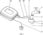
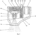
Фиг.1 - схематическое изображение разных компонентов дезинфицирующего устройства с использованием озона согласно изобретению;Figure 1 is a schematic illustration of the various components of a disinfecting device using ozone according to the invention;
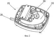
Фиг.2 - изображение генератора озона, используемого в устройстве, показанном на Фиг.1, со снятой крышкой;Figure 2 - image of the ozone generator used in the device shown in figure 1, with the cover removed;
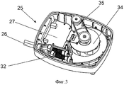
Фиг.3 - похожее изображение генератора озона с удаленными некоторыми компонентами, чтобы показать другие компоненты;Figure 3 is a similar image of an ozone generator with some components removed to show other components;
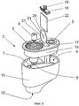
Фиг.4 - покомпонентный перспективный вид смесителя, показанного на Фиг.1;Figure 4 is an exploded perspective view of the mixer shown in Figure 1;
Фиг.5 - вид в разрезе смесителя, показанного на Фиг.1 и 4;FIG. 5 is a sectional view of the mixer shown in FIGS. 1 and 4;
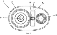
Фиг.6 - вид смесителя в плане;6 is a plan view of the mixer;
Фиг.7 - блок-схема цепи схемы пьезоэлектрического датчика; и7 is a block diagram of a circuit diagram of a piezoelectric sensor; and
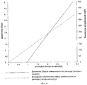
Фиг.8 - график, показывающий изменение выходного сигнала пьезоэлектрического датчика и связанной с ним схемы и давления воды против расхода через смеситель.8 is a graph showing a change in the output of a piezoelectric sensor and its associated circuit and water pressure against flow through a mixer.
ПОДРОБНОЕ ОПИСАНИЕ СО ССЫЛКАМИ НА ЧЕРТЕЖИDETAILED DESCRIPTION WITH DRAWINGS
В варианте осуществления изобретения, показанном на чертежах, дезинфицирующее устройство с использованием озона включает смеситель (2), имеющий в общем полый корпус с гнездом (3), имеющим винтовую резьбу, в качестве входа для воды под давлением, причем гнездо приспособлено для прямого соединения с выходом с винтовой резьбой водопроводного крана (4) или какого-то другого устройства подачи воды, имеющего трубный выход.In the embodiment of the invention shown in the drawings, the ozone disinfecting device comprises a mixer (2) having a generally hollow body with a socket (3) having a screw thread as an inlet for pressurized water, the socket being adapted for direct connection to an outlet with a screw thread on a water tap (4) or some other water supply device having a pipe outlet.
Вход (5) для газов, обогащенных озоном, имеет ось, параллельную оси входа для воды, но немного смещенную вбок от нее, причем камера (6) входа газа сливается сбоку с в ином цилиндрической камерой контакта (7), окружающей вход для воды. Смеситель имеет распылительную форсунку (8), которая включает завихритель (9) (смотрите Фиг.4) для создания в общем конического факела распыла (11) воды, подводимой через вход для воды (смотрите Фиг.5), так что конический факел распыла направляется в камеру контакта и к соосному выходному отверстию (12) уменьшенного диаметра, удаленному от нее. Сама камера контакта имеет размер поперечного сечения больше диаметра выходного отверстия. Распылительная форсунка соосна входу для воды, и сама форсунка расположена в общем по центру в камере контакта.The inlet (5) for gases enriched in ozone has an axis parallel to the axis of the inlet for water, but slightly offset to the side from it, and the chamber (6) of the gas inlet merges laterally with another cylindrical contact chamber (7) surrounding the water inlet. The mixer has a spray nozzle (8), which includes a swirl (9) (see Figure 4) to create a generally conical spray jet (11) of water supplied through the water inlet (see Figure 5), so that the conical spray jet is guided into the contact chamber and to the coaxial outlet (12) of reduced diameter, remote from it. The contact chamber itself has a cross-sectional dimension larger than the diameter of the outlet. The spray nozzle is aligned with the water inlet, and the nozzle itself is generally centered in the contact chamber.
Диаметр выходного отверстия, по существу, соответствует наружному диаметру конического факела распыла на этом расстоянии от форсунки, так что между наружным периметром конического факела распыла и периметром выходного отверстия свободного пространства практически не существует. Фактически, при использовании наружный периметр конического факела распыла может быть немного урезан периметром выходного отверстия, хотя необходимо предпринять усилия, чтобы эта величина не вызвала образования более крупных капель на периметре выходного отверстия.The diameter of the outlet, essentially corresponds to the outer diameter of the conical spray pattern at this distance from the nozzle, so that practically no space exists between the outer perimeter of the conical spray pattern and the perimeter of the outlet. In fact, when using the outer perimeter of the conical spray pattern, the perimeter of the outlet may be slightly trimmed, although efforts must be made so that this value does not cause the formation of larger droplets on the perimeter of the outlet.
Что касается конструкции корпуса смесителя, то он для удобства состоит из первой части (15) в форме колпака, определяющего выходное отверстие, и открытого конца напротив выходного отверстия, в который входит вторая часть (16), определяющая вход для воды, вход для газа, а также карман (17) между входом для воды и входом для газа. Боковое соединение камеры входа газа и камеры контакта в этом случае осуществлено по сторонам и ниже кармана.As for the design of the mixer housing, for convenience it consists of the first part (15) in the form of a cap defining the outlet, and the open end opposite the outlet, which includes the second part (16) that defines the inlet for water, the inlet for gas, as well as a pocket (17) between the water inlet and the gas inlet. The lateral connection of the gas inlet chamber and the contact chamber in this case is carried out on the sides and below the pocket.
Вторая часть корпуса входит в открытый конец колпака корпуса как вставка, как лучше всего видно на Фиг.4 прилагаемых чертежей. Первая и вторая части корпуса смесителя могут быть изготовлены литьем под давлением из подходящего материала, стойкого к озону, и эти две части могут быть постоянно скреплены между собой герметично любым подходящим способом, включая ультразвуковую сварку, сварку с растворителем и клеевое соединение. Отверстие кармана может быть закрыто подходящей крышкой (18), которая может быть снабжена гибкой кордной манжетой (19), которая показана на Фиг.4.The second part of the housing enters the open end of the housing cap as an insert, as best seen in Figure 4 of the accompanying drawings. The first and second parts of the mixer body can be injection molded from a suitable material resistant to ozone, and these two parts can be permanently sealed together using any suitable method, including ultrasonic welding, solvent welding and adhesive bonding. The pocket opening may be closed with a suitable lid (18), which may be provided with a flexible cord collar (19), which is shown in FIG. 4.
Смеситель включает устройство отслеживания расхода в форме пьезоэлектрического датчика (21), соединенного со связанной с ним схемой в форме печатной платы (22), генерирующей электронный сигнал, которая служит для усиления сигналов, генерируемых пьезоэлектрическим датчиком, и подает выходной сигнал, подходящий для работы схемы управления, которая описана ниже.The mixer includes a flow tracking device in the form of a piezoelectric sensor (21) connected to an associated circuit in the form of a printed circuit board (22) generating an electronic signal, which serves to amplify the signals generated by the piezoelectric sensor, and provides an output signal suitable for the operation of the circuit control, which is described below.
Для того чтобы обеспечить подходящее включение пьезоэлектрического датчика посредством вибрации, создаваемой водой, проходящей через смеситель, сам пьезоэлектрический датчик, а также связанная с ним схема в форме печатной платы (22), размещены в кармане (17) в корпусе смесителя, и остающееся пространство в кармане заполнено подходящим затвердевающим материалом. Затвердевающий материал таким образом обеспечивает надлежащую передачу вибрации на пьезоэлектрический датчик.In order to ensure a suitable connection of the piezoelectric sensor by vibration generated by water passing through the mixer, the piezoelectric sensor itself, as well as the associated circuit in the form of a printed circuit board (22), are placed in a pocket (17) in the mixer housing, and the remaining space in The pocket is filled with suitable hardening material. The hardened material thus ensures proper transmission of vibration to the piezoelectric sensor.
В одной успешной конструкции пьезоэлектрического датчика он имеет форму тонкого сжимаемого диска (23), в этом случае из пены, причем диск (23) концентрически присоединен к обеим поверхностям датчика. Уменьшенный наружный диаметр дисков из пены позволяет плотно вводить наружный периметр пьезоэлектрического датчика в затвердевающий материал. Небольшое отверстие (24) (смотрите Фиг.4) в центре диска из пены, которое ближе к гнезду, позволяет затвердевающему материалу контактировать с пьезоэлектрическим датчиком в центральной области на одной его стороне. Эффект заключается в том, что пьезоэлектрический датчик, плотно удерживаемый по его периметру и возбуждаемый небольшим стержнем (имеющим обозначение (24а) на Фиг.5) из затвердевающего материала через небольшое отверстие (24), развивает достаточное движение в результате того, что пена позволяет пьезоэлектрическому датчику вибрировать и генерировать усиленный выходной сигнал.In one successful design of the piezoelectric sensor, it has the form of a thin compressible disk (23), in this case made of foam, with the disk (23) concentrically attached to both surfaces of the sensor. The reduced outer diameter of the foam discs allows the outer perimeter of the piezoelectric sensor to be densely inserted into the hardening material. A small hole (24) (see Figure 4) in the center of the foam disk, which is closer to the socket, allows the hardened material to contact the piezoelectric sensor in the central region on one side of it. The effect is that a piezoelectric sensor tightly held around its perimeter and excited by a small rod (labeled (24a) in FIG. 5) of the hardening material through a small hole (24) develops sufficient movement as the foam allows the piezoelectric vibrate the sensor and generate an amplified output signal.
Конечно, пьезоэлектрический датчик чувствителен к вибрации, создаваемой водой, когда она проходит через форсунку, и такая вибрация будет изменяться, обычно по частоте, вместе с расходом воды. На Фиг.8 представлен график, показывающий изменение расхода по отношению к давлению и выходному сигналу пьезоэлектрического датчика и связанной с ним схемы.Of course, the piezoelectric sensor is sensitive to the vibration generated by the water when it passes through the nozzle, and such vibration will change, usually in frequency, along with the flow rate of the water. Fig. 8 is a graph showing a change in flow rate with respect to pressure and output of a piezoelectric sensor and its associated circuit.
Микропроцессор (41) предпочтительно расположен на печатной плате и позволяет включить другие интеллектуальные электронные датчики в схему смесителя, например инфракрасный датчик приближения (42) для включения форсункой, а также для соединения с водяным электромагнитным клапаном, в котором случае он может включаться самим потоком воды. Таким образом, датчик можно использовать для включения от озонирующей смывной воды, например в писсуаре.The microprocessor (41) is preferably located on the printed circuit board and allows other smart electronic sensors to be included in the mixer circuit, for example, an infrared proximity sensor (42) for inclusion by the nozzle, as well as for connection to a water solenoid valve, in which case it can be turned on by the water stream itself. Thus, the sensor can be used to turn on the ozonizing flushing water, for example in the urinal.
Просто ради полноты изложения, на Фиг.7 показан пример электронной схемы в форме блок-схемы. Следует сказать, что выходной сигнал от пьезоэлектрического датчика сначала проходит через фильтр нижних частот (43) и затем через усилитель (44). Усиленный сигнал проходит через фильтр верхних частот (45), затем через выпрямитель (46) и затем через фильтр нижних частот (47). Конечно, электронная схема может включать светодиод (LED) (48), чтобы указывать, когда работает датчик вибрации. Кроме того, дополнительной функцией светодиода в смесителе или функцией дополнительного светодиода может быть сообщение другой информации пользователю, например указание интервалов времени путем включения через каждые 15 секунд, что поможет более точно дозировать промываемые объекты. Он также может показывать ошибки или отказы устройства последовательностью включений красным светом (в противоположность зеленому или синему). Печатная плата может быть снабжена соединителем (49) для соединения с генератором озона, описанным ниже.Just for the sake of completeness, FIG. 7 shows an example of an electronic circuit in the form of a block diagram. It should be said that the output signal from the piezoelectric sensor first passes through a low-pass filter (43) and then through an amplifier (44). The amplified signal passes through a high-pass filter (45), then through a rectifier (46) and then through a low-pass filter (47). Of course, the electronic circuit may include a light emitting diode (LED) (48) to indicate when the vibration sensor is operating. In addition, an additional LED function in the mixer or an additional LED function may be the message of other information to the user, for example, indication of time intervals by switching on every 15 seconds, which will help to more accurately dose the washed objects. It can also show errors or failures of the device by a sequence of turns on in red (as opposed to green or blue). The circuit board may be provided with a connector (49) for connection with the ozone generator described below.
Отдельный генератор озона (25) общеизвестной конструкции и типа с коронным разрядом оперативно соединен подходящей трубкой (26) с входом (5) для газов, обогащенных озоном, смесителя. Такой генератор озона, однако, модифицирован для работы в настоящем изобретении и снабжен схемой управления на печатной плате (27) (смотрите Фиг.3) в корпусе генератора озона.A separate ozone generator (25) of a well-known design and type with a corona discharge is operatively connected by a suitable tube (26) to the inlet (5) for the ozone-enriched gases of the mixer. Such an ozone generator, however, is modified to operate in the present invention and is provided with a control circuit on a printed circuit board (27) (see FIG. 3) in an ozone generator housing.
Генератор озона также соединен со смесителем посредством соединительного кабеля (28), который служит для подачи электрической энергии в форме постоянного тока низкого напряжения на печатную плату (22) и пьезоэлектрический датчик (21) в кармане смесителя и для передачи сигналов, генерируемых в ответ на сигнал пьезоэлектрического датчика, на схему управления в корпусе генератора озона.The ozone generator is also connected to the mixer by means of a connecting cable (28), which serves to supply electric energy in the form of low-voltage direct current to the printed circuit board (22) and a piezoelectric sensor (21) in the pocket of the mixer and to transmit signals generated in response to the signal piezoelectric sensor, to the control circuit in the ozone generator housing.
Схема управления включает подходящий трансформатор и выпрямитель для соединения посредством подходящего кабеля (31) с электрической розеткой. Схема управления предназначена для включения генератора озона (32) коронного разряда после получения сигнала от смесителя, соответствующего минимальному заданному расходу воды через смеситель, который будет соответствовать созданию факела распыла воды, занимающего выходное отверстие из камеры контакта. Схема управления также отключает генератор озона после получения сигнала от смесителя, соответствующего расходу меньше упомянутого минимального. При этом понимается, что таким образом генерация озона в отсутствие адекватного потока воды через смеситель не осуществляется, и, вследствие этого, озон не может выбрасываться в атмосферу.The control circuit includes a suitable transformer and rectifier for connection via a suitable cable (31) to an electrical outlet. The control circuit is designed to turn on the corona discharge ozone generator (32) after receiving a signal from the mixer corresponding to the minimum specified water flow through the mixer, which will correspond to the creation of a water spray torch occupying the outlet from the contact chamber. The control circuit also turns off the ozone generator after receiving a signal from the mixer corresponding to a flow rate less than the minimum. It is understood that in this way, ozone generation in the absence of an adequate flow of water through the mixer is not carried out, and, therefore, ozone cannot be released into the atmosphere.
Генератор озона в этом варианте осуществления изобретения также включает центробежный вентилятор (33) переменной частоты вращения для подачи воздуха через генератор озона и оттуда в камеру контакта смесителя. Центробежный вентилятор имеет, по существу, известную центробежную крыльчатку (34), которая приводится в движение электродвигателем (35) постоянного тока с переменной частотой вращения. Электродвигатель с переменной частотой вращения управляется схемой управления по сигналам, принимаемым от пьезоэлектрического датчика, так что вентилятор включается до включения генератора озона и отключается после отключения генератора озона.The ozone generator in this embodiment also includes a variable speed centrifugal fan (33) for supplying air through the ozone generator and from there to the contact chamber of the mixer. The centrifugal fan has a substantially known centrifugal impeller (34), which is driven by a variable speed electric motor (35). The variable speed electric motor is controlled by a control circuit based on signals received from the piezoelectric sensor, so that the fan turns on before turning on the ozone generator and turns off after turning off the ozone generator.
При использовании создается дезинфицирующий спрей воды с озоном в качестве активного дезинфицирующего средства, причем спрей проходит через камеру контакта и выходит из выходного отверстия, так что озон выходит вместе со спреем из выходного отверстия, как сказано выше.When used, a water disinfectant spray is created with ozone as an active disinfectant, the spray passing through the contact chamber and leaving the outlet, so that the ozone leaves the outlet together with the spray, as mentioned above.
Работа дезинфицирующего устройства начинается с открытия крана, чтобы дать воде протекать через смеситель, и когда расход достигнет минимального уровня, в этом случае приблизительно 1,3 л/мин, и предпочтительно между 1,6 и 2 л/мин, схема управления сначала включит двигатель постоянного тока, который приводит в действие вентилятор, чтобы создать поток над устройством коронного разряда (32), и, вскоре после этого, подается напряжение на высоковольтную цепь устройства коронного разряда для начала генерации озона. Эта последовательность продолжается проверкой, что весь генерируемый озон поступает в смеситель. Схема управления также может включить контрольную лампу, такую как синий светодиод, чтобы указать, что воздух протекает и озон генерируется.The operation of the sanitizer begins with the opening of the tap to allow water to flow through the mixer, and when the flow reaches the minimum level, in this case approximately 1.3 l / min, and preferably between 1.6 and 2 l / min, the control circuit will first turn on the engine direct current, which drives the fan to create a flow over the corona discharge device (32), and shortly afterwards, voltage is applied to the high voltage circuit of the corona discharge device to start ozone generation. This sequence continues by verifying that all generated ozone enters the mixer. The control circuit may also include a test lamp, such as a blue LED, to indicate that air is flowing and ozone is being generated.
Когда кран будет открыт больше, пьезоэлектрический датчик в форсунке выполняет подачу сигнала увеличения расхода на схему управления, которая регулирует частоту вращения вентилятора, чтобы увеличить поток воздуха в ответ на увеличившийся расход воды. Таким образом, дезинфицирующее устройство имеет возможность отслеживать расход воды и подавать повышенное количество озона в смеситель при увеличении расхода воды.When the valve is opened more, the piezoelectric sensor in the nozzle feeds an increase in flow signal to a control circuit that adjusts the fan speed to increase air flow in response to increased water flow. Thus, the disinfecting device has the ability to track the flow of water and to supply an increased amount of ozone to the mixer with an increase in water flow.
Смесь озона с водой выходит из форсунки в форме спрея с мелкими каплями и попадает на целевой объект, который помещен или обрабатывается в водяном спрее для очистки.A mixture of ozone with water leaves the nozzle in the form of a spray with small drops and falls on the target, which is placed or processed in a water spray for cleaning.
Таким образом, воздух продувается вентилятором через устройство коронного разряда на скорости, которая изменяется согласно сигналу, принятому от пьезоэлектрического датчика и связанной с ним схемы. В этой связи следует сказать, что пьезоэлектрический датчик отслеживает вибрацию, создаваемую прохождением воды через завихритель и форсунку смесителя, и свойства вибрации будут изменяться вместе с расходом воды через смеситель.Thus, the air is blown by the fan through the corona discharge device at a speed that changes according to the signal received from the piezoelectric sensor and the associated circuit. In this regard, it should be said that the piezoelectric sensor monitors the vibration created by the passage of water through the swirl and nozzle of the mixer, and the vibration properties will change with the flow of water through the mixer.
Просто для примера, в примененном испытательном оборудовании следующие давления дали следующие указанные расходы воды и частоты вращения вентилятора при указанном содержании озона в воде.Just for example, in the applied test equipment, the following pressures gave the following indicated water flow rates and fan speeds at the indicated ozone content in water.

Несмотря на вышесказанное, следует сказать, что также определено, что немного пониженное давление, созданное в смесительной камере посредством проходящего через нее спрея, может быть достаточным для удовлетворительного потока воздуха через генератор озона, что делает вентилятор и связанные с ним средства управления ненужными с соответствующим снижением расходов. Однако в таком случае давление подачи воды должно относительно соответствовать определенному практическому диапазону давлений в водопроводной сети.Notwithstanding the foregoing, it should be said that it is also determined that a slightly reduced pressure created in the mixing chamber by means of a spray passing through it may be sufficient for a satisfactory air flow through the ozone generator, which makes the fan and associated controls unnecessary with a corresponding reduction expenses. However, in this case, the water supply pressure should relatively correspond to a certain practical pressure range in the water supply network.
Возможны многочисленные вариации и области применения изобретения. Так, например, может быть изготовлено переносное устройство как автономное устройство, носимое на плече с помощью ремня и укомплектованное резервуаром для воды, аккумулятором и распылительной трубкой. Пользователь может выполнять санитарную очистку оборудования для фитнеса или другие большие области, где нельзя применить большие объемы воды.Numerous variations and applications are possible. So, for example, a portable device can be made as a stand-alone device worn on the shoulder with a belt and equipped with a water tank, battery and spray tube. The user can sanitize fitness equipment or other large areas where large volumes of water cannot be used.
Форсунка может быть прикреплена к посудомоечной машине, чтобы создавать постоянное санитарное распыление во время цикла мойки. Такое применение может позволить снизить рабочую температуру посудомоечной машины, чтобы экономить электроэнергию.The nozzle can be attached to the dishwasher to create a constant sanitary spray during the washing cycle. Such an application may reduce the operating temperature of the dishwasher in order to save energy.
Форсунку можно прикрепить к подвесной системе создания тумана, чтобы создавать мягкий охлаждающий туман над свежей продукцией для ее охлаждения и санитарной очистки во многих ситуациях, например на рынке, в транспортном средстве или в любой другой подходящей среде.The nozzle can be attached to an overhead misting system to create a soft cooling mist over fresh produce to cool and sanitize it in many situations, such as on the market, in a vehicle or in any other suitable environment.
Устройство может использоваться в туннеле с транспортером и многочисленными форсунками, распределенными по длине туннеля, чтобы подвергать санитарной очистке объекты большого объема. Такая система может быть использована для санитарной обработки тары для упаковки рыбы или любой другой свежей продукции. Эту систему также можно использовать для санитарной обработки и удаления пестицидов с больших объемов свежей продукции в местах ее упаковки.The device can be used in a tunnel with a conveyor and numerous nozzles distributed along the length of the tunnel to sanitize large objects. Such a system can be used for the sanitization of containers for packaging fish or any other fresh produce. This system can also be used for sanitizing and removing pesticides from large volumes of fresh produce at the packaging sites.
Дезинфицирующее устройство может быть соединено с писсуаром, чтобы распылять в него обогащенную озоном воду при смывании. Таким образом можно уменьшить число бактерий и неприятные запахи.The disinfecting device can be connected to the urinal to spray ozone-rich water into it when flushing. In this way, bacteria and unpleasant odors can be reduced.
Устройство может быть размещено под прилавком или установлено на стену рядом, например, с раковиной для мытья рук.The device can be placed under the counter or mounted on a wall next to, for example, a sink for washing hands.
Возможны многочисленные варианты изобретения, не нарушающие его объем.Numerous variations of the invention are possible without violating its scope.
Claims (14)
Applications Claiming Priority (3)
| Application Number | Priority Date | Filing Date | Title |
|---|---|---|---|
| ZA2011/03473 | 2011-05-12 | ||
| ZA201103473 | 2011-05-12 | ||
| PCT/IB2012/052355 WO2012153303A1 (en) | 2011-05-12 | 2012-05-11 | Ozone -based disinfecting device comprising a flow sensor |
Publications (2)
| Publication Number | Publication Date |
|---|---|
| RU2013154980A RU2013154980A (en) | 2015-06-20 |
| RU2583813C2 true RU2583813C2 (en) | 2016-05-10 |
Family
ID=46201763
Family Applications (1)
| Application Number | Title | Priority Date | Filing Date |
|---|---|---|---|
| RU2013154980/05A RU2583813C2 (en) | 2011-05-12 | 2012-05-11 | Disinfecting device using ozone and flow sensor therefor |
Country Status (14)
| Country | Link |
|---|---|
| US (2) | US8951477B2 (en) |
| EP (1) | EP2707333B1 (en) |
| JP (1) | JP6034856B2 (en) |
| KR (1) | KR101924454B1 (en) |
| CN (1) | CN103702948B (en) |
| AU (1) | AU2012251988B2 (en) |
| BR (1) | BR112013029017B8 (en) |
| CA (1) | CA2835983C (en) |
| ES (1) | ES2609815T3 (en) |
| HK (1) | HK1192532A1 (en) |
| PL (1) | PL2707333T3 (en) |
| RU (1) | RU2583813C2 (en) |
| WO (1) | WO2012153303A1 (en) |
| ZA (1) | ZA201308456B (en) |
Families Citing this family (10)
| Publication number | Priority date | Publication date | Assignee | Title |
|---|---|---|---|---|
| BR112014013734A8 (en) | 2011-12-06 | 2017-06-13 | Masco Corp | ozone distribution on a tap |
| TWI577450B (en) * | 2014-09-05 | 2017-04-11 | 台達電子工業股份有限公司 | Nebulizer and method using the same |
| US10767270B2 (en) | 2015-07-13 | 2020-09-08 | Delta Faucet Company | Electrode for an ozone generator |
| CA2946465C (en) | 2015-11-12 | 2022-03-29 | Delta Faucet Company | Ozone generator for a faucet |
| CN108463437B (en) | 2015-12-21 | 2022-07-08 | 德尔塔阀门公司 | Fluid delivery system comprising a disinfection device |
| US10457552B2 (en) * | 2017-01-27 | 2019-10-29 | Hamilton Sundstrand Corporation | Flow sensing ozone converter |
| CN108225460A (en) * | 2017-12-29 | 2018-06-29 | 嘉兴乾昆工业设计有限公司 | A kind of intellectual water meter that can check the number of degrees immediately |
| CN112888463A (en) * | 2018-10-11 | 2021-06-01 | 美净科技私人有限公司 | Distributed sterilization system |
| CN110522049B (en) * | 2019-09-27 | 2024-02-09 | 沈阳创新设计服务有限公司 | Pesticide residue removing device for vegetable cleaning |
| US11279618B2 (en) * | 2020-03-05 | 2022-03-22 | Cashido Corporation | Ozone water supply apparatus and ozone generation device |
Citations (5)
| Publication number | Priority date | Publication date | Assignee | Title |
|---|---|---|---|---|
| RU2207985C1 (en) * | 2000-12-21 | 2003-07-10 | Лужков Юрий Михайлович | Water ozonizer and water ozonizing method |
| RU2316484C1 (en) * | 2006-05-25 | 2008-02-10 | Институт прикладной механики Российской Академии Наук (ИПРИМ РАН) | Method for water saturation with gas and bubbling plant for method realization |
| RU2374184C2 (en) * | 2006-03-23 | 2009-11-27 | Закрытое акционерное общество "Московские озонаторы" | Device for ozone treatment of drinking water |
| WO2010001279A1 (en) * | 2008-07-04 | 2010-01-07 | Cape Winds Trading 27 Cc | Disinfecting device |
| US7875173B1 (en) * | 1997-11-21 | 2011-01-25 | Barnes Ronald L | Ozone generator retrofit apparatus for jetted tubs, spas, and other water circulation facilities |
Family Cites Families (9)
| Publication number | Priority date | Publication date | Assignee | Title |
|---|---|---|---|---|
| US4462264A (en) * | 1980-08-11 | 1984-07-31 | Wilgood Corporation | Acoustic flow sensors |
| JPH0639384A (en) * | 1991-04-11 | 1994-02-15 | Tetsuo Wada | Water purifying device having function for preparing ozone water |
| JPH06160134A (en) * | 1992-11-24 | 1994-06-07 | Tokico Ltd | Fluid vibration type flow meter |
| JPH06323881A (en) * | 1993-05-12 | 1994-11-25 | Ricoh Co Ltd | Fluidic flowmeter |
| JPH07108284A (en) * | 1993-10-13 | 1995-04-25 | Seiwa Electron Kk | Ozone water generator |
| CN2401032Y (en) * | 1999-10-09 | 2000-10-18 | 顺德市桂容家电有限公司 | Sprayer used in preventing and controlling biological disease |
| JP3074465U (en) * | 2000-06-30 | 2001-01-19 | 有限会社サンワ | Ozone mixing equipment for running water |
| CN2776966Y (en) * | 2005-03-28 | 2006-05-03 | 陆绍 | Mixing device of ozone health care water apparatus |
| CN101156955B (en) * | 2007-11-21 | 2010-05-19 | 中山大学 | Non-equilibrium plasma type spray disinfection sanitizer generating apparatus |
-
2012
- 2012-05-11 EP EP12725150.2A patent/EP2707333B1/en active Active
- 2012-05-11 US US14/116,533 patent/US8951477B2/en active Active
- 2012-05-11 JP JP2014509882A patent/JP6034856B2/en active Active
- 2012-05-11 KR KR1020137033064A patent/KR101924454B1/en active IP Right Grant
- 2012-05-11 CN CN201280034088.8A patent/CN103702948B/en active Active
- 2012-05-11 RU RU2013154980/05A patent/RU2583813C2/en active
- 2012-05-11 BR BR112013029017A patent/BR112013029017B8/en active IP Right Grant
- 2012-05-11 ES ES12725150.2T patent/ES2609815T3/en active Active
- 2012-05-11 AU AU2012251988A patent/AU2012251988B2/en active Active
- 2012-05-11 CA CA2835983A patent/CA2835983C/en active Active
- 2012-05-11 WO PCT/IB2012/052355 patent/WO2012153303A1/en active Application Filing
- 2012-05-11 PL PL12725150T patent/PL2707333T3/en unknown
-
2013
- 2013-11-11 ZA ZA2013/08456A patent/ZA201308456B/en unknown
-
2014
- 2014-06-06 HK HK14105348.2A patent/HK1192532A1/en unknown
- 2014-09-02 US US14/475,032 patent/US9451787B2/en active Active
Patent Citations (5)
| Publication number | Priority date | Publication date | Assignee | Title |
|---|---|---|---|---|
| US7875173B1 (en) * | 1997-11-21 | 2011-01-25 | Barnes Ronald L | Ozone generator retrofit apparatus for jetted tubs, spas, and other water circulation facilities |
| RU2207985C1 (en) * | 2000-12-21 | 2003-07-10 | Лужков Юрий Михайлович | Water ozonizer and water ozonizing method |
| RU2374184C2 (en) * | 2006-03-23 | 2009-11-27 | Закрытое акционерное общество "Московские озонаторы" | Device for ozone treatment of drinking water |
| RU2316484C1 (en) * | 2006-05-25 | 2008-02-10 | Институт прикладной механики Российской Академии Наук (ИПРИМ РАН) | Method for water saturation with gas and bubbling plant for method realization |
| WO2010001279A1 (en) * | 2008-07-04 | 2010-01-07 | Cape Winds Trading 27 Cc | Disinfecting device |
Also Published As
| Publication number | Publication date |
|---|---|
| KR20140048132A (en) | 2014-04-23 |
| BR112013029017B1 (en) | 2020-05-05 |
| JP2014518705A (en) | 2014-08-07 |
| US8951477B2 (en) | 2015-02-10 |
| WO2012153303A1 (en) | 2012-11-15 |
| ES2609815T3 (en) | 2017-04-24 |
| CN103702948B (en) | 2016-03-16 |
| BR112013029017A2 (en) | 2018-06-26 |
| HK1192532A1 (en) | 2014-08-22 |
| JP6034856B2 (en) | 2016-11-30 |
| KR101924454B1 (en) | 2018-12-03 |
| CA2835983C (en) | 2019-12-24 |
| RU2013154980A (en) | 2015-06-20 |
| EP2707333B1 (en) | 2016-10-05 |
| EP2707333A1 (en) | 2014-03-19 |
| AU2012251988B2 (en) | 2016-11-10 |
| ZA201308456B (en) | 2014-07-30 |
| AU2012251988A1 (en) | 2013-12-05 |
| CA2835983A1 (en) | 2012-11-15 |
| US9451787B2 (en) | 2016-09-27 |
| BR112013029017B8 (en) | 2022-10-04 |
| US20140154141A1 (en) | 2014-06-05 |
| CN103702948A (en) | 2014-04-02 |
| PL2707333T3 (en) | 2017-09-29 |
| US20140369891A1 (en) | 2014-12-18 |
Similar Documents
| Publication | Publication Date | Title |
|---|---|---|
| RU2583813C2 (en) | Disinfecting device using ozone and flow sensor therefor | |
| US9392815B2 (en) | Ozone-based disinfecting device and mixer therefor | |
| US20060037869A1 (en) | Scented electrolysis product | |
| KR20100011542U (en) | Sterilizing water spraying apparatus | |
| JP2010091240A (en) | Liquid spray method and spray apparatus | |
| JP2004330050A (en) | Ozonized-water supplying apparatus and fluid mixing apparatus | |
| JP2005013714A (en) | Method and apparatus for indoor spatial sterilization | |
| JP2007111689A (en) | Spout installation-type gas-liquid mixer | |
| KR102381489B1 (en) | Portable sterilizer | |
| KR101944407B1 (en) | Apparatus for treating laundry including flow path inside | |
| KR100871416B1 (en) | Ozone sterilized water creation device | |
| KR100984304B1 (en) | Apparatus for making sterilized water and oxygen water | |
| CN209985226U (en) | Instant mixing arrangement of ozone water | |
| US9757697B2 (en) | Spray atomizing ozone water generating apparatus with gas storage ability | |
| KR102506983B1 (en) | A personal automatic ozonated water sprayer for virus prevention and sterilization and its use method | |
| KR100442314B1 (en) | Method and Apparatus for generating ozonized water and vapor and a cleaning device using the same | |
| KR101790301B1 (en) | Apparatus for treating laundry including sterilizing water | |
| KR200286647Y1 (en) | Cleaning device using a apparatus for generating ozonized water | |
| KR200237414Y1 (en) | Device For Manufacturing The Ozone Water | |
| KR101529790B1 (en) | Apparatus for disinfection using Ozone water | |
| JP2022161953A (en) | Sterilization device |