RU2573111C2 - Image forming apparatus, method of controlling said apparatus and program - Google Patents
Image forming apparatus, method of controlling said apparatus and program Download PDFInfo
- Publication number
- RU2573111C2 RU2573111C2 RU2014123375/28A RU2014123375A RU2573111C2 RU 2573111 C2 RU2573111 C2 RU 2573111C2 RU 2014123375/28 A RU2014123375/28 A RU 2014123375/28A RU 2014123375 A RU2014123375 A RU 2014123375A RU 2573111 C2 RU2573111 C2 RU 2573111C2
- Authority
- RU
- Russia
- Prior art keywords
- mode
- image forming
- controller
- trigger
- printer
- Prior art date
Links
Images
Classifications
-
- H—ELECTRICITY
- H04—ELECTRIC COMMUNICATION TECHNIQUE
- H04N—PICTORIAL COMMUNICATION, e.g. TELEVISION
- H04N1/00—Scanning, transmission or reproduction of documents or the like, e.g. facsimile transmission; Details thereof
- H04N1/00885—Power supply means, e.g. arrangements for the control of power supply to the apparatus or components thereof
- H04N1/00904—Arrangements for supplying power to different circuits or for supplying power at different levels
-
- G—PHYSICS
- G03—PHOTOGRAPHY; CINEMATOGRAPHY; ANALOGOUS TECHNIQUES USING WAVES OTHER THAN OPTICAL WAVES; ELECTROGRAPHY; HOLOGRAPHY
- G03G—ELECTROGRAPHY; ELECTROPHOTOGRAPHY; MAGNETOGRAPHY
- G03G21/00—Arrangements not provided for by groups G03G13/00 - G03G19/00, e.g. cleaning, elimination of residual charge
-
- B—PERFORMING OPERATIONS; TRANSPORTING
- B41—PRINTING; LINING MACHINES; TYPEWRITERS; STAMPS
- B41J—TYPEWRITERS; SELECTIVE PRINTING MECHANISMS, i.e. MECHANISMS PRINTING OTHERWISE THAN FROM A FORME; CORRECTION OF TYPOGRAPHICAL ERRORS
- B41J29/00—Details of, or accessories for, typewriters or selective printing mechanisms not otherwise provided for
- B41J29/38—Drives, motors, controls or automatic cut-off devices for the entire printing mechanism
-
- G—PHYSICS
- G03—PHOTOGRAPHY; CINEMATOGRAPHY; ANALOGOUS TECHNIQUES USING WAVES OTHER THAN OPTICAL WAVES; ELECTROGRAPHY; HOLOGRAPHY
- G03G—ELECTROGRAPHY; ELECTROPHOTOGRAPHY; MAGNETOGRAPHY
- G03G15/00—Apparatus for electrographic processes using a charge pattern
- G03G15/50—Machine control of apparatus for electrographic processes using a charge pattern, e.g. regulating differents parts of the machine, multimode copiers, microprocessor control
- G03G15/5004—Power supply control, e.g. power-saving mode, automatic power turn-off
-
- G—PHYSICS
- G03—PHOTOGRAPHY; CINEMATOGRAPHY; ANALOGOUS TECHNIQUES USING WAVES OTHER THAN OPTICAL WAVES; ELECTROGRAPHY; HOLOGRAPHY
- G03G—ELECTROGRAPHY; ELECTROPHOTOGRAPHY; MAGNETOGRAPHY
- G03G21/00—Arrangements not provided for by groups G03G13/00 - G03G19/00, e.g. cleaning, elimination of residual charge
- G03G21/14—Electronic sequencing control
-
- H—ELECTRICITY
- H04—ELECTRIC COMMUNICATION TECHNIQUE
- H04N—PICTORIAL COMMUNICATION, e.g. TELEVISION
- H04N1/00—Scanning, transmission or reproduction of documents or the like, e.g. facsimile transmission; Details thereof
-
- H—ELECTRICITY
- H04—ELECTRIC COMMUNICATION TECHNIQUE
- H04N—PICTORIAL COMMUNICATION, e.g. TELEVISION
- H04N1/00—Scanning, transmission or reproduction of documents or the like, e.g. facsimile transmission; Details thereof
- H04N1/00912—Arrangements for controlling a still picture apparatus or components thereof not otherwise provided for
- H04N1/00928—Initialisation or control of normal start-up or shut-down, i.e. non failure or error related
-
- H—ELECTRICITY
- H04—ELECTRIC COMMUNICATION TECHNIQUE
- H04N—PICTORIAL COMMUNICATION, e.g. TELEVISION
- H04N1/00—Scanning, transmission or reproduction of documents or the like, e.g. facsimile transmission; Details thereof
- H04N1/00912—Arrangements for controlling a still picture apparatus or components thereof not otherwise provided for
- H04N1/00931—Synchronising different operations or sub-apparatus, e.g. controlling on-times taking into account different warm-up times
Abstract
Description
ОБЛАСТЬ ТЕХНИКИ, К КОТОРОЙ ОТНОСИТСЯ ИЗОБРЕТЕНИЕFIELD OF THE INVENTION
[0001] Настоящее изобретение относится к процессу запуска устройства формирования изображения.[0001] The present invention relates to a process for starting an image forming apparatus.
УРОВЕНЬ ТЕХНИКИBACKGROUND
[0002] За последнее время, поскольку устройства формирования изображения стали многофункциональными, системы стали сложными, что в результате привело к возникновению тенденции к увеличению периода времени для запуска программных средств. Для решения этой проблемы была разработана технология сокращения периода времени для запуска программных средств. При использовании этой технологии, в случае, когда выключатель питания устройства формирования изображения находится в выключенном положении, питание подается только на память DRAM. После перевода выключателя питания во включенное положение состояние меняется с состояния, в котором питание подается только на память DRAM, на состояние, предшествующее переводу выключателя питания в выключенное положение (далее в настоящем документе будет называться запуском подачи питания на память DRAM).[0002] Recently, as the image forming apparatuses have become multifunctional, the systems have become complex, resulting in a tendency to increase the time period for launching the software. To solve this problem, a technology was developed to reduce the time period for launching software tools. When using this technology, in the case when the power switch of the imaging device is in the off position, power is supplied only to the DRAM. After the power switch is turned on, the state changes from the state in which power is supplied only to the DRAM memory to the state prior to the power switch being turned off (hereinafter, referred to as starting the power supply to the DRAM).
[0003] Например, как описано в документе PTL 1, разработана технология сокращения периода времени для запуска программных средств. При использовании этой технологии, в случае, когда выключатель питания устройства формирования изображения является выключенным, образ памяти DRAM сохраняется в энергонезависимом хранилище (например, на жестком диске). После перевода выключателя питания во включенное положение этот образ загружается в память DRAM и восстанавливается состояние, предшествующее переводу выключателя питания в выключенное положение (далее в настоящем документе будет называться запуском с пониженным энергопотреблением).[0003] For example, as described in PTL 1, a technology has been developed to reduce the time period for running software tools. Using this technology, when the power switch of the imaging device is off, the DRAM image is stored in non-volatile storage (for example, on a hard disk). After the power switch is turned on, this image is loaded into the DRAM and the state restored before the power switch is turned off (hereinafter referred to as low-power startup) is restored.
ПЕРЕЧЕНЬ ПАТЕНТНОЙ ЛИТЕРАТУРЫLIST OF PATENT LITERATURE
[0004] PTL 1: Опубликованный патент Японии №5-85020.[0004] PTL 1: Japanese Published Patent No. 5-85020.
СУЩНОСТЬ ИЗОБРЕТЕНИЯSUMMARY OF THE INVENTION
ТЕХНИЧЕСКАЯ ПРОБЛЕМАTECHNICAL PROBLEM
[0005] Устройство формирования изображения включает в себя блок контроллера заданий (далее в настоящем документе будет называться контроллером), который генерирует и обрабатывает обычное задание, и блок принтера (далее в настоящем документе будет называться принтером), который выполняет процесс печати. Контроллер и принтер имеют соответствующие процессоры CPU и выполняют части программных средств, которые являются независимыми друг от друга.[0005] The image forming apparatus includes a job controller unit (hereinafter referred to as a controller) that generates and processes a typical job, and a printer unit (hereinafter referred to as a printer) that performs a printing process. The controller and printer have corresponding CPU processors and execute pieces of software that are independent of each other.
[0006] Как было описано выше, обеспечивается технология быстрого запуска для программных средств, которая может быть использована для программных средств для контроллера.[0006] As described above, a quick start technology for software is provided that can be used for software for the controller.
[0007] В программных средствах для принтера преимущественно выполняется инициализация устройств. В связи с этим, затруднительно применять технологию сокращения времени запуска для программных средств в неизменном виде к программным средствам для принтера. Поэтому, согласно существующим условиям, только контроллер запускается быстро, чтобы он ожидал запуска принтера. В результате чего возникает проблема, заключающаяся в том, что запуск всего устройства формирования изображения занимает некоторое время.[0007] In printer software, devices are primarily initialized. In this regard, it is difficult to apply the technology to reduce startup time for software in an unchanged form for software for the printer. Therefore, according to existing conditions, only the controller starts up quickly so that it waits for the printer to start. As a result, a problem arises in that it takes some time to start the entire image forming apparatus.
[0008] Настоящее изобретение было разработано для решения вышеописанной проблемы, задача которого заключается в обеспечении механизма, который предоставляет возможность осуществления быстрого запуска всего устройства формирования изображения.[0008] The present invention was developed to solve the above problem, the task of which is to provide a mechanism that provides the ability to quickly launch the entire image forming apparatus.
РЕШЕНИЕ ПРОБЛЕМЫSOLUTION
[0009] В настоящем изобретении обеспечивается устройство формирования изображения, включающее в себя контроллер и блок формирования изображения. Устройство имеет несколько режимов запуска, включающих в себя первый режим запуска и второй режим запуска в качестве режимов запуска для контроллера. Второй режим запуска конфигурируется таким образом, чтобы период времени запуска для второго режима запуска было короче периода времени запуска для первого режима запуска. Устройство включает в себя задающее средство, первое средство управления и второе средство управления. Задающее средство задает любой режим запуска из множества режимов запуска в соответствии с командой от пользователя. Когда устройство формирования изображения должно быть запущено, первое средство управления запускает контроллер в режиме запуска, который задан задающим средством. Когда устройство формирования изображения должно быть запущено, второе средство управления запускает блок формирования изображения посредством выполнения предварительно определенного процесса инициализации в случае, когда задающим средством задан первый режим запуска, и запускает блок формирования изображения без выполнения предварительно определенного процесса инициализации в случае, когда задающим средством задан второй режим запуска.[0009] The present invention provides an image forming apparatus including a controller and an image forming unit. The device has several trigger modes, including the first trigger mode and the second trigger mode as trigger modes for the controller. The second trigger mode is configured so that the trigger time period for the second trigger mode is shorter than the trigger time period for the first trigger mode. The device includes a master means, a first control means and a second control means. The master means sets any trigger mode from a plurality of trigger modes in accordance with a command from the user. When the imaging device is to be started, the first control means starts the controller in the start mode, which is set by the master means. When the image forming apparatus is to be started, the second control means starts the image forming unit by performing a predetermined initialization process in the case where the first trigger mode is set by the setting means, and starts the image forming unit without performing the predetermined initialization process in the case when the setting means second launch mode.
ВЫГОДНЫЕ ЭФФЕКТЫ ИЗОБРЕТЕНИЯFAVORABLE EFFECTS OF THE INVENTION
[0010] Настоящее изобретение предоставляет возможность обеспечения механизма, который обеспечивает быстрый запуск всего устройства формирования изображения.[0010] The present invention provides the ability to provide a mechanism that enables quick startup of the entire image forming apparatus.
КРАТКОЕ ОПИСАНИЕ ЧЕРТЕЖЕЙBRIEF DESCRIPTION OF THE DRAWINGS
[0011] Фиг. 1 изображает блок-схемы, демонстрирующие иллюстративную конфигурацию устройства формирования изображения в соответствии с вариантом осуществления настоящего изобретения.[0011] FIG. 1 is a block diagram showing an illustrative configuration of an image forming apparatus in accordance with an embodiment of the present invention.
Фиг. 2 изображает последовательность иллюстративных операций контроллера 1 и принтера 4 в устройстве формирования изображения в соответствии с первым вариантом осуществления настоящего изобретения.FIG. 2 shows a sequence of illustrative operations of a controller 1 and a printer 4 in an image forming apparatus according to a first embodiment of the present invention.
Фиг. 3 изображает графическое представление, демонстрирующее иллюстративный период времени запуска для каждого из режимов запуска для контроллера 1, а также иллюстративные периоды времени процесса инициализации для принтера 4.FIG. 3 is a graphical view showing an illustrative start-up time period for each of the start-up modes for the controller 1, as well as illustrative time periods of the initialization process for the printer 4.
Фиг. 4 изображает последовательность иллюстративных операций контроллера 1 и принтера 4 в устройстве формирования изображения в соответствии со вторым вариантом осуществления настоящего изобретения.FIG. 4 depicts a sequence of illustrative operations of a controller 1 and a printer 4 in an image forming apparatus according to a second embodiment of the present invention.
ОПИСАНИЕ ВАРИАНТОВ ОСУЩЕСТВЛЕНИЯDESCRIPTION OF EMBODIMENTS
[0012] Далее, посредством ссылок на чертежи, будут описаны предпочтительные варианты осуществления настоящего изобретения. Компоненты, которые описываются в вариантах осуществления, попросту являются примерами, при этом объем настоящего изобретения не ограничивается этими компонентами.[0012] Next, by reference to the drawings, preferred embodiments of the present invention will be described. The components that are described in the embodiments are merely examples, and the scope of the present invention is not limited to these components.
ПЕРВЫЙ ВАРИАНТ ОСУЩЕСТВЛЕНИЯFIRST IMPLEMENTATION
[0013] Фиг. 1(a) изображает блок-схему, демонстрирующую иллюстративную конфигурацию устройства формирования изображения, в соответствии с вариантом осуществления настоящего изобретения.[0013] FIG. 1 (a) is a block diagram showing an illustrative configuration of an image forming apparatus in accordance with an embodiment of the present invention.
[0014] На Фиг. 1(a) ссылочной позицией 1 обозначается контроллер устройства формирования изображения, при этом контроллер 1 включает в себя основную плату 100 и дополнительную плату 120.[0014] FIG. 1 (a), reference numeral 1 denotes a controller of an image forming apparatus, wherein controller 1 includes a main board 100 and an additional board 120.
[0015] Основная плата 100 является так называемой системой универсальных процессоров CPU. Процессор 101 CPU управляет всей основной платой 100. Загрузочная память 102 ROM записывает загрузочные программы машиночитаемым способом. Память 103 является основной памятью, используемой в качестве рабочей (оперативной) памяти посредством процессора 101 CPU.[0015] The main board 100 is a so-called system of universal processors CPU. The processor 101 CPU controls the entire main board 100. The boot memory 102 ROM writes boot programs in a machine-readable manner. The memory 103 is the main memory used as the working (operational) memory by the processor 101 CPU.
[0016] Контроллер 104 шины имеет функцию построения моста с внешней шиной. Энергонезависимая память 105 является хранилищем, в котором данные могут содержаться без потерь даже в случае прерывания подачи питания. RTC 110 являются часами, которые управляют использованием питания, подаваемого от батареи даже в случае прерывания подачи питания на основную плату 100.[0016] The bus controller 104 has a function of constructing a bridge with an external bus. Non-volatile memory 105 is a storage in which data can be stored without loss even in the event of a power outage. RTC 110s are clocks that control the use of battery power even in the event of a power failure to main board 100.
[0017] Контроллер 106 диска управляет блоком хранения. Контроллер 108 шины USB управляет шиной USB. Диск 107 флэш-памяти является блоком хранения относительно малой емкости, например твердотельным накопителем (SSD), включающим в себя полупроводниковое устройство.[0017] The disk controller 106 controls the storage unit. The USB bus controller 108 controls the USB bus. The flash drive 107 is a relatively low capacity storage unit, for example, a solid state drive (SSD) including a semiconductor device.
[0018] Память 9 USB, операционный блок 5 и жесткий диск 6 соединяются с основной платой 100. Жесткий диск 6 не должен в обязательном порядке являться жестким диском, поскольку он является энергонезависимым хранилищем, при этом в качестве жесткого диска 6 может быть использовано энергонезависимое хранилище любого типа.[0018] A USB memory 9, an operation unit 5, and a hard disk 6 are connected to the main board 100. The hard disk 6 does not have to be a hard disk, as it is a non-volatile storage, and a non-volatile storage can be used as a hard disk 6 any type.
[0019] Дополнительная плата 120 включает в себя относительно малую систему универсальных процессоров CPU и аппаратные средства обработки изображения. Процессор 121 CPU управляет всей дополнительной платой 120. Процессор 121 CPU использует память 123 в качестве рабочей (оперативной) памяти. Контроллер 124 шины имеет функцию построения моста с внешней шиной.[0019] The option board 120 includes a relatively small system of universal CPU processors and image processing hardware. The processor 121, the CPU controls the entire additional board 120. The processor 121, the CPU uses the memory 123 as a working (operational) memory. The bus controller 124 has a function of constructing a bridge with an external bus.
[0020] Энергонезависимая память 125 является хранилищем, в котором данные могут содержаться без потерь даже в случае прерывания подачи питания. Процессор 127 обработки изображений выполняет обработку цифрового изображения в реальном времени.[0020] Non-volatile memory 125 is a storage in which data can be stored without loss even in the event of a power outage. An image processing processor 127 performs real-time digital image processing.
[0021] Сканер 2 (блок сканера) и принтер 4 (блок принтера) принимают/передают данные цифрового изображения через контроллеры 126 устройств. Процессор 121 CPU непосредственно управляет факсом 7 (блоком факсимильной связи).[0021] Scanner 2 (scanner unit) and printer 4 (printer unit) receive / transmit digital image data via device controllers 126. The processor 121 CPU directly controls the fax 7 (facsimile unit).
[0022] Блок 8 питания подает питание на основную плату 100 и дополнительную плату 120. Контроллер 109 подачи питания управляет питанием, которое подается с блока 8 питания, таким образом, чтобы питание подавалось на те блоки основной платы 100, которые нуждаются в этом. Контроллер 128 подачи питания управляет питанием, которое подается с блока 8 питания, таким образом, чтобы питание подавалось на те блоки дополнительной платы 120, которые нуждаются в этом.[0022] The power supply unit 8 supplies power to the main board 100 and the additional board 120. The power supply controller 109 controls the power that is supplied from the power supply unit 8 so that power is supplied to those units of the main board 100 that need it. The power supply controller 128 controls the power that is supplied from the power unit 8, so that power is supplied to those units of the option board 120 that need it.
[0023] Питание подается, например, на память USB, операционный блок 5, жесткий диск 6, принтер 4, сканер 2 и факс 7 через контроллер 1.[0023] Power is supplied, for example, to a USB memory, an operation unit 5, a hard disk 6, a printer 4, a scanner 2, and a fax 7 through the controller 1.
[0024] Переключатель 10 является выключателем питания, с которым пользователь выполняет действия по включению/выключению. Когда переключатель 10 приводится в действие, работа процессора 101 CPU прерывается. Когда процессор 101 CPU обнаруживает прерывание, процессор 101 CPU управляет контроллером 109 подачи питания в соответствии с состоянием процессора 101 CPU. Процессор 121 CPU обнаруживает действие с переключателем 10 через контроллеры 104 и 124 шины и управляет контроллером 128 подачи питания.[0024] The switch 10 is a power switch with which the user performs on / off actions. When the switch 10 is actuated, the operation of the CPU 101 of the CPU is interrupted. When the CPU 101 detects an interrupt, the CPU 101 controls the power supply controller 109 in accordance with the state of the CPU 101. The processor 121 of the CPU detects the action with the switch 10 through the bus controllers 104 and 124 and controls the power supply controller 128.
[0025] Фиг. 1(a) изображает блок-схему, демонстрирующую упрощенную иллюстрацию. Например, процессор 101 CPU, процессор 121 CPU и т.п. включает в себя большое количество частей периферийных аппаратных средств процессора CPU, таких как набор микросхем, мост шины и генератор тактовых импульсов. Однако эти части периферийных аппаратных средств процессора CPU не должны быть в обязательном порядке иллюстрированы в контексте уровня описания и на графическом представлении опущены. В связи с этим данная конфигурация блока не ограничивается настоящим изобретением.[0025] FIG. 1 (a) is a block diagram showing a simplified illustration. For example, CPU 101, CPU 121, and the like. It includes a large number of peripheral hardware parts of the CPU processor, such as a chipset, a bus bridge, and a clock. However, these parts of the peripheral hardware of the CPU processor need not be necessarily illustrated in the context of the description level and omitted in a graphical representation. In this regard, this configuration of the block is not limited to the present invention.
[0026] Принтер 4 включает в себя процессор 41 CPU, память 42 ROM, память 43 RAM и энергонезависимое хранилище 44. Процессор 41 CPU выполняет программы, сохраненные в памяти 42 ROM посредством использования памяти 43 RAM, благодаря чему достигается выполнение различных операций. Принтер 4 сохраняет в энергонезависимом хранилище 44 нижеописанный режим запуска для контроллера 1.[0026] The printer 4 includes a CPU processor 41, a ROM memory 42, a RAM memory 43, and non-volatile storage 44. The CPU processor 41 executes programs stored in the ROM memory 42 by using the RAM memory 43, thereby achieving various operations. Printer 4 stores in non-volatile storage 44 the following startup mode for controller 1.
[0027] Операции контроллера 1 будут описываться ниже в качестве примера посредством снятия копии изображения с листа бумаги.[0027] The operations of the controller 1 will be described below as an example by taking a copy of an image from a sheet of paper.
[0028] Когда пользователь передает с операционного блока 5 команду копирования изображения, процессор 101 CPU обнаруживает эту команду и побуждает сканер 2 к считыванию изображения через процессор 121 CPU. После приема команды считывания изображения сканер 2 выполняет оптическое сканирование печатного документа и преобразовывает оптические данные в данные цифрового изображения, которые передаются через контроллер 126 устройства на процессор 127 обработки изображений. После приема данных цифрового изображения процессор 127 обработки изображений выполняет передачу DMA данных цифрового изображения через процессор 121 CPU в память 123, в которой временно сохраняются данные цифрового изображения.[0028] When the user transmits an image copy command from the operation unit 5, the CPU processor 101 detects this command and causes the scanner 2 to read the image through the CPU processor 121. After receiving the image reading command, the scanner 2 performs an optical scan of the printed document and converts the optical data into digital image data, which is transmitted through the device controller 126 to the image processing processor 127. After receiving the digital image data, the image processing processor 127 transmits the DMA of the digital image data through the processor 121 to the memory 123, in which the digital image data is temporarily stored.
[0029] Когда процессор 101 CPU определяет, что конкретное количество или целостность данных цифрового изображения сохранена в памяти 123, процессор 101 CPU передает команду вывода изображения через процессор 121 CPU на принтер 4, а также уведомляет процессор 127 обработки изображений о расположении (адресе) данных изображения в памяти 123. Процессор 127 обработки изображений, который принял команду вывода изображения, передает данные изображения, сохраненные в ячейке памяти 123, которые получают посредством уведомления, через контроллер 126 устройства на принтер 4, в соответствии с сигналом синхронизации, принятым от принтера 4.[0029] When the CPU 101 determines that a specific amount or integrity of digital image data is stored in the memory 123, the CPU 101 transmits an image output command through the CPU 121 to the printer 4, and also notifies the image processing processor 127 of the data location (address) images in the memory 123. The image processing processor 127, which has received the image output command, transmits the image data stored in the memory cell 123, which are received by notification, through the device controller 126 to nter 4 in accordance with the synchronization signal received from the printer 4.
[0030] Когда принтер 4 принимает данные изображения через контроллер 126 устройства, принтер 4 распечатывает данные изображения на листе бумаги.[0030] When the printer 4 receives the image data through the device controller 126, the printer 4 prints the image data on a sheet of paper.
[0031] В случае, когда требуется распечатать две и более копий, процессор 101 CPU сохраняет данные изображения в памяти 123 на жестком диске 6. В процессе печати второй и последующих копий, вместо приема данных изображения от сканера 2, процессор 101 CPU осуществляет управление таким образом, чтобы передавать данные изображения, сохраненные на жестком диске 6, на принтер 4 и выполнять печать на принтере 4.[0031] In the case where it is required to print two or more copies, the CPU 101 stores the image data in the memory 123 on the hard disk 6. In the process of printing the second and subsequent copies, instead of receiving image data from the scanner 2, the CPU 101 controls so as to transfer image data stored on the hard disk 6 to the printer 4 and print on the printer 4.
[0032] Далее будет кратко описан режим запуска для контроллера (блока управления). В режиме обычного запуска (первом режиме запуска) для запуска контроллера программы разворачиваются в энергозависимом средстве хранения. В режиме запуска с подачей питания на память DRAM (втором режиме запуска) для запуска контроллера используется образ памяти, сохраненный в энергозависимом средстве хранения. В режиме запуска с пониженным энергопотреблением (третьем режиме запуска) для запуска контроллера образ памяти, сохраненный в энергонезависимом средстве хранения, считывается в энергозависимое средство хранения.[0032] Next, a startup mode for the controller (control unit) will be briefly described. In normal startup mode (first launch mode), programs are deployed in a volatile storage medium to start the controller. In startup mode with power to DRAM (second startup mode), a memory image stored in a volatile storage medium is used to start the controller. In the low-power startup mode (third startup mode), to start the controller, a memory image stored in the non-volatile storage medium is read into the non-volatile storage medium.
[0033] Далее со ссылкой на Фиг. 1(b) будет описано состояние подачи питания в устройстве формирования изображения в случае, когда контроллер 1 является выключенным в режиме запуска с подачей питания на память DRAM.[0033] Next, with reference to FIG. 1 (b), the power supply state in the image forming apparatus will be described when the controller 1 is turned off in the startup mode with the DRAM memory energized.
[0034] Фиг. 1(b) изображает графическое представление, демонстрирующее иллюстративное состояние подачи питания в устройстве формирования изображения в случае, когда контроллер 1 является выключенным в режиме запуска с подачей питания на память DRAM.[0034] FIG. 1 (b) is a graphical view showing an illustrative state of power supply in the image forming apparatus when the controller 1 is turned off in the start mode with power to the DRAM.
[0035] Как иллюстрировано на Фиг. 1(b), когда контроллер 1 является выключенным в режиме запуска с подачей питания на память DRAM, устройство формирования изображения входит в состояние, в котором питание подается только на память 103 и переключатель 10 основной платы 100 контроллера 1. Образ памяти, который был получен перед отключением подачи питания, сохраняется в памяти 103, благодаря чему достигается быстрый запуск контроллера 1 при подаче питания. То есть в режиме запуска с подачей питания на память DRAM контроллер 1 продолжает подавать питание на память 103 контроллера 1 даже несмотря на то, что переключатель 10 находится в выключенном положении. После перевода переключателя 10 во включенное положение контроллер 1 использует данные, сохраненные в памяти 103, для восстановления состояния, предшествующего переводу переключателя 10 в выключенное положение.[0035] As illustrated in FIG. 1 (b), when the controller 1 is turned off in the startup mode with power being supplied to the DRAM, the image forming apparatus enters a state in which power is supplied only to the memory 103 and the switch 10 of the main board 100 of the controller 1. The memory image that was received before turning off the power supply, is stored in the memory 103, thereby achieving a quick start of the controller 1 when power is applied. That is, in the startup mode with power to the DRAM memory, the controller 1 continues to supply power to the memory 103 of the controller 1 even though the switch 10 is in the off position. After moving the switch 10 to the on position, the controller 1 uses the data stored in the memory 103 to restore the state prior to moving the switch 10 to the off position.
[0036] В противном случае, когда контроллер 1 является выключенным в режиме запуска с пониженным энергопотреблением, устройство формирования изображения входит в состояние, в котором подача питания на все элементы устройства формирования изображения прерывается. Образ памяти, предшествующий отключению подачи питания, сохраняется на жестком диске 6 или диске 107 флэш-памяти и разворачивается в памяти 103 посредством использования передачи DMA после запуска, благодаря чему достигается быстрый запуск контроллера 1. То есть в режиме запуска с пониженным энергопотреблением, когда переключатель 10 переводится в выключенное положение, контроллер 1 сохраняет на диске 107 флэш-памяти данные, сохраненные в памяти 103. После перевода переключателя 10 во включенное положение контроллер 1 загружает в память 103 данные, сохраненные на диске 107 флэш-памяти, для восстановления состояния, предшествующего переводу переключателя 10 в выключенное положение.[0036] Otherwise, when the controller 1 is turned off in the start-up mode with reduced power consumption, the image forming apparatus enters a state in which power supply to all elements of the image forming apparatus is interrupted. The memory image preceding the power-off is stored on the hard disk 6 or the flash drive 107 and expanded in the memory 103 by using DMA transmission after startup, thereby achieving a quick start of the controller 1. That is, in the startup mode with low power consumption when the switch 10 is turned off, the controller 1 saves the data stored in the memory 103 on the flash drive 107. After the switch 10 is turned on, the controller 1 loads the data into the memory 103, Saving to disk flash memory 107, to restore the state before the transfer switch 10 to the OFF position.
[0037] При сравнении запуска в режиме запуска с пониженным энергопотреблением с запуском в режиме запуска с подачей питания на память DRAM,выясняется, что энергопотребление в режиме запуска с пониженным энергопотреблением в состоянии отключенной подачи питания, как правило, меньше энергопотребления в режиме запуска с подачей питания на память DRAM на величину, соответствующую величине питания, подаваемого на память 103 и переключатель 10. Однако при запуске в режиме запуска с пониженным энергопотреблением период времени запуска превышает период времени запуска в режиме подачи питания на память DRAM на период времени, необходимый для разворачивания образа памяти с жесткого диска 6 или диска 107 флэш-памяти в память 103.[0037] When comparing a start in a low power start mode with a start in a start mode with power to the DRAM, it turns out that the power consumption in the low power start mode in the power off state is generally less than the power in the start power mode power to the DRAM by an amount corresponding to the amount of power supplied to the memory 103 and the switch 10. However, when starting in the startup mode with reduced power consumption, the start time period exceeds the period d start time in the mode of supplying power to the DRAM for the period of time necessary to deploy the image of the memory from the hard disk 6 or the disk 107 flash memory in the memory 103.
[0038] При запуске в режиме обычного запуска, поскольку процессор 101 CPU последовательно считывает образ с жесткого диска 6 или диска 107 флэш-памяти в память 103, запуск занимает некоторое время. В то же время, при запуске в режиме обычного запуска, контроллер 1 каждый раз запускается с начального состояния, благодаря чему гарантируется эксплуатационная стабильность.[0038] When starting in the normal startup mode, since the CPU 101 sequentially reads the image from the hard disk 6 or the flash drive 107 to the memory 103, the startup takes some time. At the same time, when starting in the normal start-up mode, the controller 1 each time starts from the initial state, thereby guaranteeing operational stability.
[0039] Для быстрого запуска устройства формирования изображения с небольшим количеством питания, потребляемым в состоянии отключенной подачи питания, используется режим запуска с подачей питания на память DRAM. Для быстрого запуска устройства формирования изображения без питания, потребляемого в состоянии отключенной подачи питания, используется режим запуска с пониженным энергопотреблением. В случае, когда запуск может занять некоторое время, используется режим обычного запуска.[0039] To quickly start the image forming apparatus with a small amount of power consumed in the power off state, a start mode with power supply to the DRAM is used. To quickly start the imaging device without power consumed in the off-state power supply, the low-power start mode is used. In the case when the launch may take some time, the usual launch mode is used.
[0040] Операционный блок 5 используется для переключения режима между режимом обычного запуска, режимом запуска с подачей питания на память DRAM и режимом запуска с пониженным энергопотреблением. Отличительные признаки вышеописанных режимов запуска отображаются в меню переключения режимов запуска на блоке отображения, обеспеченном для операционного блока 5, при этом операционный блок 5 принимает установочные параметры для режима запуска посредством выбора, выполняемого посредством пользователя. Далее в настоящем документе режим запуска с подачей питания на память DRAM и режим запуска с пониженным энергопотреблением будут совместно называться режимом быстрого запуска. Режим запуска с подачей питания на память DRAM также называется первым режимом быстрого запуска, а режим запуска с пониженным энергопотреблением также называется вторым режимом быстрого запуска.[0040] The operation unit 5 is used to switch the mode between the normal start mode, the start mode with power to the DRAM and the low power start mode. Distinctive features of the above trigger modes are displayed in the trigger mode switching menu on the display unit provided for the operation unit 5, while the operation unit 5 receives settings for the start mode by means of a selection made by the user. Hereinafter, the startup mode with power to the DRAM and the startup mode with reduced power consumption will be collectively referred to as the quick start mode. The start mode with power to the DRAM is also called the first quick start mode, and the low power start mode is also called the second quick start mode.
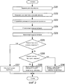
[0041] Далее, со ссылкой на Фиг. 2 будут описаны операции устройства формирования изображения, в соответствии с первым вариантом осуществления настоящего изобретения. Фиг. 2 изображает последовательность иллюстративных операций контроллера 1 и принтера 4 в устройстве формирования изображения в соответствии с первым вариантом осуществления настоящего изобретения. Выполнение операций контроллера 1 достигается посредством процессора 101 CPU контроллера 1, который считывает программы, записанные в загрузочной памяти 102 ROM машиночитаемым способом, и выполняет программы. Выполнение операций принтера 4 достигается посредством процессора 41 CPU принтера 4, который считывает программы, записанные в памяти 42 ROM машиночитаемым способом, и выполняет программы.[0041] Next, with reference to FIG. 2, operations of an image forming apparatus according to a first embodiment of the present invention will be described. FIG. 2 shows a sequence of illustrative operations of a controller 1 and a printer 4 in an image forming apparatus according to a first embodiment of the present invention. The execution of the operations of the controller 1 is achieved by the processor 101 of the CPU of the controller 1, which reads the programs recorded in the boot memory 102 ROM in a machine-readable manner and executes the programs. The operation of the printer 4 is achieved by the processor 41 of the CPU of the printer 4, which reads the programs recorded in the ROM memory 42 in a machine-readable manner, and executes the programs.
[0042] На этапе S201, после обнаружения установочных параметров режима запуска для контроллера 1, который задается пользователем при помощи операционного блока 5, процессор 101 CPU сохраняет режим запуска, который был задан, в энергонезависимой памяти 105. При следующем запуске процессор 101 CPU осуществляет управление таким образом, чтобы запускать контроллер 1 посредством использования этого режима запуска.[0042] In step S201, after detecting the start-up mode settings for the controller 1, which is set by the user using the operation unit 5, the CPU 101 stores the start-up mode that has been set in the non-volatile memory 105. At the next start, the CPU 101 controls so as to start controller 1 by using this start mode.
[0043] На этапе S202 процессор 101 CPU уведомляет процессор 121 CPU о режиме запуска, который был задан на этапе S201, через контроллеры 104 и 124 шины. Процессор 121 CPU, который принимает это уведомление, уведомляет принтер 4 о режиме запуска, принятом от процессора 101 CPU, через контроллер 126 устройства.[0043] In step S202, the CPU 101 notifies the processor 121 of the CPU of the startup mode that was set in step S201 through the bus controllers 104 and 124. The CPU 121, which receives this notification, notifies the printer 4 of the startup mode received from the CPU 101 through the device controller 126.
[0044] После приема уведомления о режиме запуска от процессора 121 CPU процессор 41 CPU принтера 4 сохраняет режим запуска, принятый от процессора 121 CPU, в энергонезависимом хранилище 44 (на этапе S203).[0044] After receiving the start mode notification from the CPU 121, the processor 41 of the printer CPU 4 stores the start mode received from the CPU 121 in the non-volatile storage 44 (in step S203).
[0045] Когда пользователь выполняет действия с переключателем 10 и переводит переключатель 10 в выключенное положение, процессор 101 CPU обнаруживает перевод переключателя 10 в выключенное положение, выполняет необходимый завершающий процесс и отключает подачу питания на устройство формирования изображения через контроллер 109 подачи питания (на этапе S204).[0045] When the user performs operations with the switch 10 and sets the switch 10 to the off position, the CPU 101 detects the switch 10 is turned off, performs the necessary completion process, and turns off the power to the image forming apparatus via the power supply controller 109 (in step S204 )
[0046] Когда пользователь выполняет действия с переключателем 10 и переводит переключатель 10 во включенное положение (на этапе S205), питание подается на блоки, включающие в себя контроллер 1 и принтер 4. В блоках, включающих в себя контроллер 1 и принтер 4, начинается выполнение различных необходимых процессов запуска.[0046] When the user performs the operations with the switch 10 and sets the switch 10 to the on position (in step S205), power is supplied to the units including the controller 1 and the printer 4. In the units including the controller 1 and the printer 4, starts performing various necessary startup processes.
[0047] На этапе S206 процессор 41 CPU принтера 4 считывает режим запуска для контроллера 1, который был сохранен в энергонезависимом хранилище 44 на этапе S203, а затем определяет, является ли режим запуска режимом быстрого запуска.[0047] In step S206, the processor 4 of the printer CPU 4 reads a startup mode for the controller 1, which was stored in the non-volatile storage 44 in step S203, and then determines whether the startup mode is a quick startup mode.
[0048] Если было определено, что режим запуска для контроллера 1 не является режимом быстрого запуска, то есть режим запуска является режимом обычного запуска (отрицательный результат определения, выполняемого на этапе S206), то процессор 41 CPU принтера 4 выполняет обычный запуск, в процессе которого выполняются все различные операции инициализации принтера 4 (на этапе S207).[0048] If it was determined that the start mode for controller 1 is not a quick start mode, that is, the start mode is the normal start mode (negative result of the determination performed in step S206), then the processor 41 of the printer CPU 4 performs a normal start, in the process which performs all the various initialization operations of the printer 4 (in step S207).
[0049] Если на этапе S206 было определено, что режим запуска для контроллера 1, который был сохранен в энергонезависимом хранилище 44 на этапе S203, является режимом быстрого запуска (положительный результат определения), то процессор 41 CPU принтера 4 выполняет быстрый запуск, при котором принтер 4 изменяет различные операции инициализации (на этапах S208-S210).[0049] If it was determined in step S206 that the startup mode for the controller 1, which was stored in the non-volatile storage 44 in step S203, is a quick start mode (positive result), then the processor 41 of the printer CPU 4 performs a quick start in which printer 4 changes various initialization operations (in steps S208-S210).
[0050] На этапе S208 процессор 41 CPU принтера 4 определяет, является ли режим запуска для контроллера 1, который был сохранен в энергонезависимом хранилище 44 на этапе S203, первым режимом быстрого запуска.[0050] In step S208, the printer processor 4 of the printer 4 determines whether the start mode for the controller 1, which was stored in the non-volatile storage 44 in step S203, is the first quick start mode.
[0051] Если было определено, что режим запуска для контроллера 1 является первым режимом быстрого запуска, то есть режимом запуска с подачей питания на память DRAM (положительный результат определения, выполняемого на этапе S208), то процессор 41 CPU принтера 4 выполняет первый режим быстрого запуска (на этапе S209).[0051] If it was determined that the start mode for controller 1 is the first fast start mode, that is, the start mode with power to the DRAM (positive result of determination performed in step S208), then the processor CPU 41 of the printer 4 performs the first fast mode start (at step S209).
[0052] Если на этапе S208 было определено, что режим запуска для контроллера 1, который был сохранен в энергонезависимом хранилище 44 на этапе S203, не является первым режимом быстрого запуска, то есть является вторым режимом быстрого запуска, который является режимом запуска с пониженным энергопотреблением (отрицательный результат определения), то процессор 41 CPU принтера 4 выполняет второй режим быстрого запуска (на этапе S210).[0052] If it was determined in step S208 that the start-up mode for the controller 1, which was stored in the non-volatile storage 44 in step S203, is not the first quick-start mode, that is, the second quick-start mode, which is the low-power start-up mode (negative result of determination), the processor 41 of the CPU of the printer 4 performs the second quick start mode (at step S210).
[0053] Уведомление о режиме запуска, которое передается с контроллера 1 на принтер 4 и описывается на этапе S202, может быть передано в течение процесса, выполняемого на этапе S204, или же сразу после этапа S205. В случае передачи уведомления о режиме запуска сразу после этапа S205, операция, выполняемая на этапе S203, на котором режим запуска сохраняется в энергонезависимом хранилище, не является необходимой. В этом случае если уведомление о режиме запуска не передается в максимально сжатые сроки после этапа S205, то это затрудняет переключение процесса запуска принтера 4.[0053] A start mode notification that is transmitted from the controller 1 to the printer 4 and is described in step S202 can be transmitted during the process in step S204, or immediately after step S205. In the case of transmitting the start mode notification immediately after step S205, the operation performed in step S203, in which the start mode is stored in non-volatile storage, is not necessary. In this case, if the start mode notification is not transmitted as soon as possible after step S205, then this makes it difficult to switch the start-up process of the printer 4.
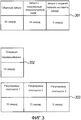
[0054] Фиг. 3 изображает графическое представление, демонстрирующее иллюстративный период времени запуска для каждого из режимов запуска для контроллера 1, а также иллюстративные периоды времени процесса инициализации для принтера 4.[0054] FIG. 3 is a graphical view showing an illustrative start-up time period for each of the start-up modes for the controller 1, as well as illustrative time periods of the initialization process for the printer 4.
[0055] На Фиг. 3 ссылочной позицией 301 обозначаются иллюстративные периоды времени запуска для режимов запуска для контроллера 1. В данном примере период времени запуска для режима обычного запуска задается равным 30 секундам. Период времени запуска для режима запуска с пониженным энергопотреблением задается равным 15 секундам, а период времени запуска для режима запуска с подачей питания на память DRAM задается равным 5 секундам. Эти режимы запуска соответствуют режиму запуска, который передается с контроллера 1 на принтер 4 на этапе S202, изображенном на Фиг. 2. Принтер 4 выполняет различные операции инициализации в соответствии с периодом времени запуска для принятого режима запуска для контроллера 1.[0055] In FIG. 3,
[0056] Ссылочными позициями 302 и 303 обозначаются примеры различных операций инициализации устройств в принтере 4. В настоящем варианте осуществления операции инициализации принтера 4 включают в себя две группы операций, а именно операцию 302 перемешивания тонера и операцию 303 регулировки плотности тонера.[0056]
[0057] Рабочий период времени (период времени от начала до завершения операции) для операции 302 перемешивания тонера равен 10 секундам.[0057] The working time period (a period of time from the beginning to the end of the operation) for the
[0058] Ссылочной позицией 303 обозначаются регулировки плотности тонера. Способы регулировки плотности включают в себя три типа (регулировки плотности 1-3), рабочие периоды времени которых не являются эквивалентными. Рабочий период времени для регулировки плотности 1 равен 10 секундам, для регулировки плотности 2-15 секундам, а для регулировки плотности 3-5 секундам.[0058]
[0059] Операции регулировки плотности (регулировки плотности 1-3), включенные в операционную группу 303, не могут выполняться параллельно. Операция 302 перемешивания и операционная группа 303 регулировки плотности могут выполняться параллельно.[0059] Density adjustment operations (density adjustments 1-3) included in the
[0060] Например, в случае, когда режим запуска, передаваемый с контроллера 1 на принтер 4 на этапе S202, изображенном на Фиг. 2, является «режимом обычного запуска», запуск контроллера 1 занимает 30 секунд. В связи с этим принтер 4 выполняет запуск, в процессе которого выполняются все операции инициализации операции перемешивания, регулировка плотности 1, регулировка плотности 2 и регулировка плотности 3 (в общей сложности за 30 секунд). Поэтому устройство формирования изображения полностью запускается через 30 секунд.[0060] For example, in the case where the startup mode transmitted from the controller 1 to the printer 4 in step S202 shown in FIG. 2, is the "normal start-up mode", the start-up of controller 1 takes 30 seconds. In this regard, the printer 4 performs a launch, during which all operations of initializing the stirring operation, density adjustment 1, density adjustment 2 and density adjustment 3 (for a total of 30 seconds) are performed. Therefore, the image forming apparatus fully starts after 30 seconds.
[0061] В случае, когда режим запуска, передаваемый с контроллера 1 на принтер 4 на этапе S202, изображенном на Фиг. 2, является «режимом запуска с пониженным энергопотреблением», запуск контроллера 1 занимает 15 секунд. В связи с этим принтер 4 выполняет запуск, в процессе которого пропускаются некоторые операции инициализации. В частности, принтер 4 запускается с пропуском регулировки плотности 1 и регулировки плотности 3, или же с пропуском регулировки плотности 2. Поэтому принтер 4 может быть быстро запущен через 15 секунд (что соответствует периоду времени запуска для контроллера 1). Соответственно, устройство формирования изображения может быть полностью быстро запущено через 15 секунд.[0061] In the case where the start mode transmitted from the controller 1 to the printer 4 in step S202 shown in FIG. 2, is the “low power start mode”, the start of controller 1 takes 15 seconds. In this regard, the printer 4 performs a startup, during which some initialization operations are skipped. In particular, the printer 4 starts up with a skip of density adjustment 1 and a density adjustment of 3, or with a skip of density adjustment 2. Therefore, the printer 4 can be quickly started after 15 seconds (which corresponds to the start-up period for controller 1). Accordingly, the image forming apparatus can be fully quickly started in 15 seconds.
[0062] В случае, когда режим запуска, передаваемый с контроллера 1 на принтер 4 на этапе S202, изображенном на Фиг.2, является «режимом запуска с подачей питания на память DRAM», запуск контроллера 1 занимает 5 секунд. В связи с этим принтер 4 выполняет запуск, в процессе которого пропускаются некоторые операции инициализации. В частности, принтер 4 запускается с пропуском регулировки плотности 1 и регулировки плотности 2, выполняя лишь регулировку плотности 3. Поэтому принтер 4 может быть быстро запущен через 5 секунд (что соответствует периоду времени запуска для контроллера 1). Соответственно, устройство формирования изображения может быть полностью быстро запущено через 5 секунд.[0062] In the case where the start-up mode transmitted from the controller 1 to the printer 4 in step S202 of FIG. 2 is a “start-up mode with power supply to the DRAM”, the start-up of the controller 1 takes 5 seconds. In this regard, the printer 4 performs a startup, during which some initialization operations are skipped. In particular, the printer 4 starts up with a skip of density adjustment 1 and density adjustment 2, performing only density adjustment 3. Therefore, printer 4 can be quickly started after 5 seconds (which corresponds to the start time period for controller 1). Accordingly, the image forming apparatus can be fully quickly started in 5 seconds.
[0063] Таким образом, в соответствии с настоящим вариантом осуществления, операции инициализации принтера 4 включают в себя множество операционных групп, которые могут выполняться параллельно. Каждая из операционных групп включает в себя одну или более операции, которые не могут выполняться параллельно. В случае, когда требуется изменить операции инициализации принтера 4, процессор 41 CPU принтера 4 пропускает некоторые или все операции в некоторых или всех операционных группах, в соответствии с периодом времени запуска для контроллера 1. Поэтому принтер 4 может быть запущен быстро. Могут быть пропущены все операции инициализации принтера 4.[0063] Thus, in accordance with the present embodiment, initialization operations of the printer 4 include a plurality of operating groups that can be executed in parallel. Each of the operating groups includes one or more operations that cannot be performed in parallel. In the case where it is necessary to change the initialization operations of the printer 4, the processor 41 of the CPU of the printer 4 skips some or all of the operations in some or all of the operating groups, in accordance with the start time period for the controller 1. Therefore, the printer 4 can be started up quickly. All printer initialization operations 4 may be skipped.
[0064] В альтернативном варианте некоторые или все операции инициализации принтера 4 могут быть заменены другими операциями, имеющими более короткие периоды времени выполнения. Кроме того, некоторые операции инициализации принтера 4 могут быть заменены другими операциями, имеющими более короткие периоды времени выполнения, при этом некоторые из них могут быть пропущены (конфигурация, в которой замена операций объединена с пропуском операций). То есть при условии изменения операции инициализации принтера 4 в соответствии с периодом времени запуска для контроллера 1 любая конфигурация является рабочей.[0064] Alternatively, some or all of the initialization operations of the printer 4 may be replaced by other operations having shorter runtimes. In addition, some initialization operations of the printer 4 may be replaced by other operations having shorter runtimes, some of which may be skipped (a configuration in which the replacement of operations is combined with skipping operations). That is, provided that the initialization operation of the printer 4 is changed in accordance with the start time period for the controller 1, any configuration is operational.
[0065] Как было описано выше, посредством уведомления принтера 4 о режиме запуска для контроллера 1, принтер 4 изменяет операции инициализации в соответствии с периодом времени запуска для контроллера 1, благодаря чему достигается быстрый запуск. В результате предоставляется возможность решения проблемы, вследствие которой период времени запуска для всего устройства формирования изображения является большим, поскольку только контроллер запускается быстро и ожидает завершения запуска принтера, благодаря чему достигается быстрый запуск всего устройства формирования изображения.[0065] As described above, by notifying the printer 4 of the start mode for the controller 1, the printer 4 changes the initialization operations in accordance with the start time period for the controller 1, thereby achieving quick start. As a result, it is possible to solve a problem due to which the start time period for the entire image forming apparatus is large, since only the controller starts up quickly and waits for the printer to start up, thereby achieving a quick start of the entire image forming apparatus.
[0066] Как было описано выше, в случае, когда режим запуска для контроллера 1 является режимом быстрого запуска, после перевода переключателя 10 во включенное положение, процессор 41 CPU принтера 4 изменяет операции инициализации принтера 4 в соответствии с периодом времени запуска для контроллера, который требуется при выполнении запуска в режиме быстрого запуска, и запускает принтер 4. Например, процессор 41 CPU принтера 4 изменяет (пропускает и/или заменяет) операции инициализации принтера 4 таким образом, чтобы период времени запуска для принтера 4 не превышал период времени запуска для контроллера 1, который требуется при выполнении запуска в режиме быстрого запуска.[0066] As described above, in the case where the start mode for the controller 1 is a quick start mode, after the switch 10 is turned on, the processor 41 of the printer CPU 4 changes the initialization operations of the printer 4 in accordance with the start time period for the controller, which required when starting in quick start mode, and starts the printer 4. For example, the processor 41 of the printer 4 CPU changes (skips and / or replaces) the initialization of the printer 4 so that the start time period for the printer 4 did not exceed the start time period for controller 1, which is required when starting in quick start mode.
[0067] Процессор 41 CPU принтера 4 может изменять (пропускать и/или заменять) операции инициализации принтера 4 таким образом, чтобы период времени запуска для контроллера 1, который требуется при выполнении запуска в режиме быстрого запуска, был меньше предварительно определенного периода времени (например, меньше 5 секунд).[0067] The processor 41 of the CPU of the printer 4 can change (skip and / or replace) the initialization operations of the printer 4 so that the start time period for the controller 1, which is required when performing the start in quick start mode, is less than a predetermined time period (for example less than 5 seconds).
[0068] Процессор 41 CPU принтера 4 может изменять (пропускать и/или заменять) операции инициализации принтера 4 таким образом, чтобы минимизировать разницу между периодом времени запуска для контроллера 1, который требуется при выполнении запуска в режиме быстрого запуска, и периодом времени запуска для принтера 4. Например, предположим, что период времени запуска для контроллера 1 в режиме запуска с пониженным энергопотреблением составляет 13 секунд. В этом случае принтер 4 выполняет запуск, в процессе которого пропускается регулировка плотности 1 и регулировка плотности 3 или же пропускается регулировка плотности 2. Поэтому принтер 4 может быть быстро запущен через 15 секунд с минимизацией разницы между периодом времени запуска для контроллера 1 и периодом времени запуска для принтера 4, несмотря на то, что период времени запуска для принтера 4 превышает период времени запуска для контроллера 1.[0068] The processor 41 of the printer 4 CPU may change (skip and / or replace) the initialization operations of the printer 4 so as to minimize the difference between the start-up time period for controller 1, which is required when starting up in quick start mode, and the start-up time period for printer 4. For example, suppose that the start time period for controller 1 in the low power start mode is 13 seconds. In this case, printer 4 starts up, during which density adjustment 1 and density adjustment 3 are skipped, or density adjustment 2 is skipped. Therefore, printer 4 can be quickly started after 15 seconds, minimizing the difference between the start time period for controller 1 and the start time period for printer 4, although the start time period for printer 4 is longer than the start time period for controller 1.
ВТОРОЙ ВАРИАНТ ОСУЩЕСТВЛЕНИЯSECOND EMBODIMENT
[0069] В соответствии с первым вариантом осуществления, в случае задания для контроллера 1 режима быстрого запуска, принтер 4 всегда выполняет быстрый запуск, в процессе которого изменяются операции инициализации. В случае изменения (пропуска и/или замены) операций инициализации принтера 4, когда период времени отключения подачи питания является длительным, состояние тонера и т.п. может вызвать, например, изменение цвета. В соответствии со вторым вариантом осуществления, в случае, когда период времени отключенной подачи питания превышает предварительно определенный период времени, принтер 4 запускается посредством выполнения операции обычного запуска без изменения операций инициализации принтера 4. Далее, со ссылкой на Фиг. 4 будет представлено подробное описание.[0069] According to the first embodiment, in the case of setting the quick start mode for the controller 1, the printer 4 always performs a quick start, during which initialization operations are changed. In the case of a change (skipping and / or replacement) of the initialization operations of the printer 4, when the period of time the power supply is turned off is long, the state of the toner, etc. may cause, for example, a color change. According to the second embodiment, in the case where the time period of the disconnected power supply exceeds a predetermined time period, the printer 4 is started by performing a normal start operation without changing the initialization operations of the printer 4. Next, with reference to FIG. 4 will be presented in detail.
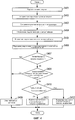
[0070] Фиг. 4 изображает последовательность иллюстративных операций контроллера 1 и принтера 4 в устройстве формирования изображения в соответствии со вторым вариантом осуществления настоящего изобретения. Выполнение операций контроллера 1 достигается посредством процессора 101 CPU контроллера 1, который считывает программы, записанные в загрузочной памяти 102 ROM машиночитаемым способом, и выполняет программы. Выполнение операции принтера 4 достигается посредством процессора 41 CPU принтера 4, который считывает программы, записанные в памяти 42 ROM машиночитаемым способом, и выполняет программы.[0070] FIG. 4 depicts a sequence of illustrative operations of a controller 1 and a printer 4 in an image forming apparatus according to a second embodiment of the present invention. The execution of the operations of the controller 1 is achieved by the processor 101 of the CPU of the controller 1, which reads the programs recorded in the boot memory 102 ROM in a machine-readable manner and executes the programs. The operation of the printer 4 is achieved by the processor 41 of the CPU of the printer 4, which reads the programs recorded in the ROM memory 42 in a machine-readable manner, and executes the programs.
[0071] На этапе S401, после обнаружения установочных параметров режима запуска для контроллера 1, которое задается пользователем при помощи операционного блока 5, процессор 101 CPU сохраняет режим запуска, который был задан, в энергонезависимой памяти 105. При следующем запуске процессор 101 CPU осуществляет управление таким образом, чтобы запускать контроллер 1 посредством использования этого режима запуска.[0071] In step S401, after the setting of the start mode settings for the controller 1, which is set by the user using the operation unit 5, is detected, the CPU 101 stores the startup mode that was set in the non-volatile memory 105. At the next start, the CPU 101 controls so as to start controller 1 by using this start mode.
[0072] На этапе S402 процессор 101 CPU уведомляет процессор 121 CPU о режиме запуска, который был задан на этапе S401, через контроллеры 104 и 124 шины. Процессор 121 CPU, который принимает это уведомление, уведомляет принтер 4 о режиме запуска, принятом от процессора 101 CPU, через контроллер 126 устройства.[0072] In step S402, the CPU 101 notifies the CPU 121 of the startup mode that was set in step S401 through the bus controllers 104 and 124. The CPU 121, which receives this notification, notifies the printer 4 of the startup mode received from the CPU 101 through the device controller 126.
[0073] После приема уведомления о режиме запуска от процессора 121 CPU процессор 41 CPU принтера 4 сохраняет режим запуска, принятый от процессора 121 CPU, в энергонезависимом хранилище 44 (на этапе S403).[0073] After receiving the start mode notification from the CPU 121, the processor 41 of the printer CPU 4 stores the start mode received from the CPU 121 in the non-volatile storage 44 (in step S403).
[0074] Когда пользователь выполняет действия с переключателем 10 и переводит переключатель 10 в выключенное положение, процессор 101 CPU обнаруживает перевод переключателя 10 в выключенное положение и запускает RTC 110 для измерения периода времени отключенной подачи питания устройства формирования изображения. Затем процессор 101 CPU выполняет необходимый завершающий процесс и отключает подачу питания на устройство формирования изображения через контроллер 109 подачи питания (на этапе S404).[0074] When the user performs operations with the switch 10 and sets the switch 10 to the off position, the CPU 101 detects that the switch 10 is turned to the off position and starts the RTC 110 to measure the period of time the power supply of the image forming apparatus has been turned off. Then, the CPU 101 performs the necessary completion process and turns off the power supply to the image forming apparatus through the power supply controller 109 (in step S404).
[0075] Когда пользователь выполняет действия с переключателем 10 и переводит переключатель 10 во включенное положение (на этапе S405), питание подается на блоки, включающие в себя контроллер 1 и принтер 4. В блоках, включающих в себя контроллер 1 и принтер 4, начинается выполнение различных необходимых процессов запуска. Процессор 101 CPU контроллера 1 останавливает RTC 110, которые были запущены на этапе S404.[0075] When the user performs the operations with the switch 10 and sets the switch 10 to the on position (in step S405), power is supplied to the units including the controller 1 and the printer 4. In the units including the controller 1 and the printer 4, starts performing various necessary startup processes. The processor 101 of the CPU of controller 1 stops the RTC 110 that were started in step S404.
[0076] На этапе S406 процессор 101 CPU вычисляет (получает) период времени отключенной подачи питания, указывающий период времени, в течение которого переключатель 10 находится в выключенном положении (время, прошедшее от этапа S404 до этапа S405) на основе значения таймера RTC 110 и уведомляет процессор 121 CPU о периоде времени отключенной подачи питания через контроллеры 104 и 124 шины. Процессор 121 CPU, который принимает это уведомление, уведомляет принтер 4 о периоде времени отключенной подачи питания, принятом от процессора 101 CPU, через контроллер 126 устройства.[0076] In step S406, the CPU 101 calculates (obtains) a time period of the disconnected power supply indicating a period of time during which the switch 10 is in the off position (the time elapsed from step S404 to step S405) based on the timer value of RTC 110 and notifies the processor 121 CPU of the time period of the disconnected power supply via the bus controllers 104 and 124. The CPU 121, which receives this notification, notifies the printer 4 of the time period of the disconnected power supply received from the processor 101 of the CPU through the device controller 126.
[0077] На этапе S407 процессор 41 CPU принтера 4 считывает режим запуска для контроллера 1, который был сохранен в энергонезависимом хранилище 44 на этапе S203, и определяет, является ли режим запуска режимом быстрого запуска.[0077] In step S407, the processor 4 of the printer CPU 4 reads the startup mode for the controller 1, which was stored in the non-volatile storage 44 in step S203, and determines whether the startup mode is a quick start mode.
[0078] Если было определено, что режим запуска для контроллера 1 не является режимом быстрого запуска, то есть режим запуска является режимом обычного запуска (отрицательный результат определения, выполняемого на этапе S407), то процессор 41 CPU принтера 4 выполняет обычный запуск, в процессе которого выполняются все различные операции инициализации принтера 4 (на этапе S408).[0078] If it was determined that the start mode for controller 1 is not a quick start mode, that is, the start mode is a normal start mode (negative result of determination performed in step S407), then the processor 41 of the printer CPU 4 performs a normal start, in the process which performs all the various initialization operations of the printer 4 (in step S408).
[0079] Если на этапе S407 было определено, что режим запуска для контроллера 1, который был сохранен в энергонезависимом хранилище 44 на этапе S203, является режимом быстрого запуска (положительный результат определения), то процессор 41 CPU принтера 4 побуждает процесс обработки к переходу на этап S409.[0079] If it was determined in step S407 that the start-up mode for the controller 1, which was stored in the non-volatile storage 44 in step S203, is a quick-start mode (positive result), then the processor 4 of the printer 4 causes the processing to proceed to step S409.
[0080] На этапе S409 процессор 41 CPU принтера 4 определяет, превышает ли порог период времени отключенной подачи питания, принятый на этапе S406. В настоящем варианте осуществления порог задается равным восьми часам. Порог зависит от характеристик принтера 4 и может являться любым периодом времени. Также может использоваться несколько пороговых ступеней.[0080] In step S409, the processor processor 41 of the printer 4 determines whether the threshold exceeds the time period of the cut off power supply adopted in step S406. In the present embodiment, the threshold is set to eight hours. The threshold depends on the characteristics of the printer 4 and can be any period of time. Several threshold stages may also be used.
[0081] Если было определено, что период времени отключенной подачи питания превышает порог (положительный результат определения, выполняемого на этапе S409), то процессор 41 CPU принтера 4 побуждает процесс обработки к переходу на этап S408 и запускает принтер обычным образом (на этапе S408). То есть в случае, когда период времени отключенной подачи питания превышает порог, процессор 41 CPU принтера 4 осуществляет управление таким образом, чтобы не изменять операции инициализации принтера 4, независимо от режима запуска для контроллера 1.[0081] If it has been determined that the time period of the disconnected power supply exceeds a threshold (a positive determination is made in step S409), the processor 41 of the printer CPU 4 prompts the processing to go to step S408 and starts the printer in the usual way (in step S408) . That is, in the case where the time period of the disconnected power supply exceeds a threshold, the processor 41 of the CPU of the printer 4 controls so as not to change the initialization operations of the printer 4, regardless of the startup mode for the controller 1.
[0082] Если было определено, что период времени отключенной подачи питания не превышает порог (отрицательный результат определения, выполняемого на этапе S409), то процессор 41 CPU принтера 4 выполняет быстрый запуск, в процессе которого принтер 4 изменяет различные операции инициализации (на этапах S410 - S412).[0082] If it was determined that the time period of the disconnected power supply does not exceed the threshold (negative result of the determination made in step S409), the processor 41 of the CPU of the printer 4 performs a quick start during which the printer 4 changes various initialization operations (in steps S410 - S412).
[0083] На этапе S410 процессор 41 CPU принтера 4 определяет, является ли режим запуска для контроллера 1, который был сохранен в энергонезависимом хранилище 44 на этапе S403, первым режимом быстрого запуска.[0083] In step S410, the processor 4 of the printer 4 CPU determines whether the start mode for the controller 1, which was stored in the non-volatile storage 44 in step S403, is the first quick start mode.
[0084] Если было определено, что режим запуска для контроллера 1 является первым режимом быстрого запуска, то есть режимом запуска с подачей питания на память DRAM (положительный результат определения, выполняемого на этапе S410), то процессор 41 CPU принтера 4 выполняет первый режим быстрого запуска (на этапе S411).[0084] If it was determined that the start mode for controller 1 is the first quick start mode, that is, the start mode with power to the DRAM (positive determination made in step S410), then the processor CPU 4 of the printer 4 executes the first fast mode start (at step S411).
[0085] Если на этапе S410 было определено, что режим запуска для контроллера 1, который был сохранен в энергонезависимом хранилище 44 на этапе S203, не является первым режимом быстрого запуска, то есть является вторым режимом быстрого запуска, который является режимом запуска с пониженным энергопотреблением (отрицательный результат определения), то процессор 41 CPU принтера 4 выполняет второй режим быстрого запуска (на этапе S412).[0085] If it was determined in step S410 that the start mode for the controller 1, which was stored in the non-volatile storage 44 in step S203, is not the first quick start mode, that is, the second quick start mode, which is the low power start mode (negative determination result), the processor 41 of the CPU of the printer 4 performs the second quick start mode (at step S412).
[0086] Подобно первому варианту осуществления, уведомление о режиме запуска, которое передается с контроллера 1 на принтер 4 и описывается на этапе S402, может быть передано в течение процесса, выполняемого на этапе S404, сразу после этапа S405 или на этапе S406. В случае передачи уведомления о режиме запуска сразу после этапа S405 или на этапе S406, операция, выполняемая на этапе S203, на котором режим запуска сохраняется в энергонезависимом хранилище, не является необходимой. В этом случае, если уведомление о режиме запуска не передается в максимально сжатые сроки после этапа S205 или на этапе S406, то это затрудняет переключение процесса запуска принтера 4.[0086] Like the first embodiment, a start mode notification that is transmitted from the controller 1 to the printer 4 and is described in step S402 can be transmitted during the process in step S404, immediately after step S405 or in step S406. In the case of sending a start mode notification immediately after step S405 or step S406, the operation performed in step S203, in which the start mode is stored in non-volatile storage, is not necessary. In this case, if the start mode notification is not transmitted as soon as possible after step S205 or step S406, this makes it difficult to switch the start-up process of the printer 4.
[0087] Как было описано выше, уведомление принтера 4 о периоде времени отключенной подачи питания контроллера 1 может побудить к запрету изменения операций инициализации в случае, когда период времени отключенной подачи питания является длительным и когда операции инициализации принтера 4 являются необходимыми.[0087] As described above, notifying the printer 4 of a time period for the power-off of the controller 1 may prohibit changing initialization operations in the case where the time-period of the power-off is long and when the initialization operations of the printer 4 are necessary.
[0088] В настоящем варианте осуществления описывается конфигурация, в которой для измерения периода времени отключенной подачи питания используются RTC 110 контроллера 1. В альтернативном варианте принтер 4 может быть оборудован таймером для измерения периода времени отключенной подачи питания, при этом период времени отключенной подачи питания может быть измерен в принтере 4.[0088] In the present embodiment, a configuration is described in which the RTC 110 of controller 1 is used to measure the time period of the power cut off. Alternatively, the printer 4 may be equipped with a timer to measure the time period of the power cut off, while the time period of the power cut can be measured in printer 4.
[0089] В случае, когда период времени отключенной подачи питания превышает порог, принтер 4 запускается обычным образом на этапе S408. В связи с этим контроллер 1 не должен запускаться быстро. Порог, используемый для определения принтера 4, сохраняется в энергонезависимой памяти 105 контроллера 1 заблаговременно. После включения подачи питания (на этапе S405) определяется, превышает ли порог период времени отключенной подачи питания. Если период времени отключенной подачи питания превышает порог, то быстрый запуск контроллера 1 не выполняется. Поэтому запуск контроллера 1 может быть сконфигурирован таким образом, чтобы он согласовывался с запуском принтера 4.[0089] In the case where the time period of the disconnected power supply exceeds a threshold, the printer 4 is started normally in step S408. In this regard, the controller 1 should not start quickly. The threshold used to determine the printer 4 is stored in non-volatile memory 105 of the controller 1 in advance. After turning on the power supply (in step S405), it is determined whether the threshold exceeds the time period of the disconnected power supply. If the time period of the disconnected power supply exceeds the threshold, then the quick start of the controller 1 is not performed. Therefore, the start of controller 1 can be configured so that it matches the start of printer 4.
[0090] В альтернативном варианте контроллер 1 может иметь порог, который согласовывается с характеристиками контроллера 1, может вычислять период времени отключенной подачи питания на этапе S405 и может запускаться обычным образом вместо выполнения быстрого запуска контроллера 1. В этом случае контроллер 1 на этапе S406 уведомляет принтер 4 о невыполнении быстрого запуска, при этом принтер 4 также запускается обычным образом.[0090] In an alternative embodiment, the controller 1 may have a threshold that is consistent with the characteristics of the controller 1, may calculate the time period of the disconnected power supply in step S405, and may start normally instead of performing a quick start of the controller 1. In this case, the controller 1 in step S406 notifies printer 4 about failure of quick start, while printer 4 also starts in the usual way.
[0091] Как было описано выше, в случае, когда период времени отключенной подачи питания превышает порог, даже если режим запуска для контроллера 1 является режимом быстрого запуска, принтер 4 не изменяет операции инициализации и запускается обычным образом посредством выполнения операции обычной инициализации. Поэтому, когда подача питания отключается на короткий период времени, устройство формирования изображения может быть запущено быстро. В отличие от этого, когда подача питания отключается на длительный период времени, выполняются операции инициализации принтера 4, которые не подвергались изменению, при этом инициализируется состояние принтера 4, что позволяет предотвратить ухудшение качества формируемых изображений. То есть может быть достигнут как быстрый запуск, так и формирование высококачественного изображения.[0091] As described above, in the case where the time period of the disconnected power supply exceeds the threshold, even if the start mode for the controller 1 is the quick start mode, the printer 4 does not change the initialization operation and starts in the usual way by performing the normal initialization operation. Therefore, when the power supply is turned off for a short period of time, the image forming apparatus can be started up quickly. In contrast, when the power supply is turned off for a long period of time, the initialization operations of the printer 4 are performed, which have not been changed, and the state of the printer 4 is initialized, which helps to prevent deterioration of the quality of the generated images. That is, both quick start and high-quality image formation can be achieved.
[0092] Вышеописанная конфигурация и значения различных данных не ограничиваются вышеупомянутыми. Разумеется, что различные конфигурации и значения могут быть использованы в соответствии со способом и целью применения.[0092] The above configuration and values of various data are not limited to the above. Of course, that various configurations and values can be used in accordance with the method and purpose of use.
[0093] Выше были описаны варианты осуществления. Однако настоящее изобретение может быть реализовано, например, в качестве системы, устройства, способа, программы или носителя записи. В частности, настоящее изобретение может быть применено к системе, включающей в себя множество элементов аппаратных средств, или же может быть применено к устройству, состоящему из одного элемента аппаратных средств.[0093] Embodiments have been described above. However, the present invention can be implemented, for example, as a system, device, method, program, or recording medium. In particular, the present invention can be applied to a system including a plurality of hardware elements, or can be applied to a device consisting of a single hardware element.
[0094] Кроме того, в настоящее изобретение включаются все конфигурации, в которых вышеописанные варианты осуществления объединяются друг с другом.[0094] Furthermore, all configurations in which the above described embodiments are combined with each other are included in the present invention.
[0095] Настоящее изобретение не ограничивается вышеописанными вариантами осуществления. Могут быть выполнены различные модификации и изменения, не отступая от сущности и объема настоящего изобретения. Формула изобретения прилагается ниже для информирования широкой публики об объеме настоящего изобретения.[0095] The present invention is not limited to the above-described embodiments. Various modifications and changes may be made without departing from the spirit and scope of the present invention. The claims are appended below to inform the general public of the scope of the present invention.
[0096] Настоящая заявка испрашивает приоритет по заявке на патент Японии № 2011-244671, поданной 8 ноября 2011 года, которая полностью включена в настоящий документ посредством ссылки.[0096] This application claims priority to Japanese Patent Application No. 2011-244671, filed November 8, 2011, which is incorporated herein by reference in its entirety.
Claims (10)
задающее средство для задания любого режима запуска из множества режимов запуска в соответствии с командой от пользователя;
первое средство управления для запуска контроллера в режиме запуска, который задан задающим средством, когда устройство формирования изображения должно быть запущено;
второе средство управления для запуска блока формирования изображения посредством выполнения предварительно определенного процесса инициализации в случае, когда задающим средством задан первый режим запуска, и запуска блока формирования изображения без выполнения предварительно определенного процесса инициализации в случае, когда задающим средством задан второй режим запуска, когда устройство формирования изображения должно быть запущено.1. An image forming apparatus including a controller and an image forming unit, wherein said device has a plurality of trigger modes including a first trigger mode and a second trigger mode as trigger modes for the controller, the second trigger mode being configured so that the start time period for the second start mode was shorter than the start time period for the first start mode, wherein said device comprises:
specifying means for setting any trigger mode from a plurality of trigger modes in accordance with a command from a user;
first control means for starting the controller in a start mode, which is set by the master means, when the image forming apparatus is to be started;
second control means for triggering the image forming unit by performing a predetermined initialization process in the case where the first trigger mode is set, and triggering the image forming unit without performing the predefined initialization process in the case where the second triggering mode is specified by the master means when the shaping device Images must be running.
в котором множество режимов запуска включает в себя третий режим запуска, сконфигурированный таким образом, чтобы период
времени запуска для третьего режима запуска был короче периода времени запуска для первого режима запуска и превышал период времени запуска для второго режима запуска.2. The image forming apparatus according to claim 1,
wherein a plurality of trigger modes includes a third trigger mode configured so that the period
the start time for the third start mode was shorter than the start time period for the first start mode and exceeded the start time period for the second start mode.
в котором, когда устройство формирования изображения должно быть запущено, в случае задания задающим средством третьего режима запуска, второе средство управления запускает блок формирования изображения посредством выполнения другого процесса инициализации вместо предварительно определенного процесса инициализации.3. The image forming apparatus according to claim 2,
in which, when the image forming apparatus is to be started, in the case of setting the third trigger mode by the setting means, the second control means starts the image forming unit by performing another initialization process instead of the predetermined initialization process.
в котором в первом режиме запуска программа развертывается в энергозависимом средстве хранения и выполняется запуск.4. The imaging device according to any one of paragraphs. 1-3,
in which, in the first launch mode, the program is deployed in a volatile storage medium and startup is performed.
в котором во втором режиме запуска для выполнения запуска используется образ памяти, сохраненный в энергозависимом средстве хранения.5. The image forming apparatus according to claim 1,
in which, in a second launch mode, a memory image stored in a volatile storage medium is used to perform a launch.
в котором в третьем режиме запуска запуск выполняется посредством считывания образа памяти, сохраненного в энергонезависимом средстве хранения, в энергозависимое средство хранения.6. The image forming apparatus according to claim 2 or 3,
wherein in the third startup mode, startup is performed by reading a memory image stored in the non-volatile storage medium into the volatile storage medium.
в котором процесс инициализации включает в себя операцию перемешивания и регулировку плотности.7. The image forming apparatus according to claim 1,
in which the initialization process includes a stirring operation and density adjustment.
в котором предварительно определенный процесс инициализации является частью регулировки плотности.8. The image forming apparatus according to claim 1,
in which a predefined initialization process is part of the density adjustment.
задают любой режим запуска из множества режимов запуска в соответствии с командой от пользователя;
запускают контроллер в режиме запуска, который задан в установочных параметрах режима запуска, когда устройство формирования изображения должно быть запущено;
запускают блок формирования изображения посредством выполнения предварительно определенного процесса инициализации в случае, когда в установочных параметрах режима запуска задан первый режим запуска, и запускают блок формирования изображения без выполнения предварительно определенного процесса инициализации в случае, когда в установочных параметрах режима запуска задан второй режим запуска, когда устройство формирования изображения должно быть запущено.9. A method for controlling an image forming apparatus including a controller and an image forming unit, wherein said device has a plurality of trigger modes including a first trigger mode and a second trigger mode as trigger modes for the controller, the second trigger mode being configured in this way so that the start time period for the second start mode is shorter than the start time period for the first start mode, wherein said method comprises the steps of:
set any trigger mode from a variety of trigger modes in accordance with a command from the user;
start the controller in the start mode, which is set in the settings of the start mode, when the imaging device should be started;
the image forming unit is started by executing a predetermined initialization process in the case when the first start mode is set in the start-up settings, and the image forming unit is started without performing the pre-defined initialization process in the case when the second start-up mode is set in the settings of the start mode, when the imaging device must be started.
включает в себя контроллер и блок формирования изображения, при этом упомянутое устройство имеет множество режимов запуска, включающих в себя первый режим запуска и второй режим запуска в качестве режимов запуска для контроллера, причем второй режим запуска конфигурируется таким образом, чтобы период времени запуска для второго режима запуска был короче периода времени запуска для первого режима запуска, при этом упомянутые операции содержат:
задание любого режима запуска из множества режимов запуска в соответствии с командой от пользователя;
запуск контроллера в режиме запуска, который задан в установочных параметрах режима запуска, когда устройство формирования изображения должно быть запущено;
запуск блока формирования изображения посредством выполнения предварительно определенного процесса инициализации в случае, когда в установочных параметрах режима запуска задан первый режим запуска, и запуск блока формирования изображения без выполнения предварительно определенного процесса инициализации в случае, когда в установочных параметрах режима запуска задан второй режим запуска, когда устройство формирования изображения должно быть запущено. 10. A computer-readable medium comprising a program stored thereon causing the image forming apparatus to perform operations, said apparatus
includes a controller and an imaging unit, wherein said device has a plurality of trigger modes including a first trigger mode and a second trigger mode as trigger modes for the controller, the second trigger mode being configured so that a trigger time period for the second mode the start was shorter than the start time period for the first start mode, while the operations mentioned include:
setting any launch mode from a variety of launch modes in accordance with a command from the user;
starting the controller in the start mode, which is set in the settings of the start mode, when the imaging device should be started;
starting the image forming unit by performing a predetermined initialization process in the case when the first starting mode is set in the setting parameters of the start mode, and starting the image forming unit without performing the predefined initialization process in the case when the second starting mode is set in the setting parameters of the starting mode when the imaging device must be started.
Applications Claiming Priority (3)
| Application Number | Priority Date | Filing Date | Title |
|---|---|---|---|
| JP2011-244671 | 2011-11-08 | ||
| JP2011244671A JP5984361B2 (en) | 2011-11-08 | 2011-11-08 | Image forming apparatus, image forming apparatus control method, and program |
| PCT/JP2012/078833 WO2013069679A1 (en) | 2011-11-08 | 2012-11-07 | Image forming apparatus, method for controlling image forming apparatus, and program |
Publications (2)
| Publication Number | Publication Date |
|---|---|
| RU2014123375A RU2014123375A (en) | 2015-12-20 |
| RU2573111C2 true RU2573111C2 (en) | 2016-01-20 |
Family
ID=48290053
Family Applications (1)
| Application Number | Title | Priority Date | Filing Date |
|---|---|---|---|
| RU2014123375/28A RU2573111C2 (en) | 2011-11-08 | 2012-11-07 | Image forming apparatus, method of controlling said apparatus and program |
Country Status (8)
| Country | Link |
|---|---|
| US (1) | US9621754B2 (en) |
| EP (1) | EP2778798B1 (en) |
| JP (1) | JP5984361B2 (en) |
| KR (1) | KR101636184B1 (en) |
| CN (1) | CN103917924B (en) |
| BR (1) | BR112014010507B1 (en) |
| RU (1) | RU2573111C2 (en) |
| WO (1) | WO2013069679A1 (en) |
Families Citing this family (8)
| Publication number | Priority date | Publication date | Assignee | Title |
|---|---|---|---|---|
| JP6048020B2 (en) * | 2012-09-13 | 2016-12-21 | 株式会社リコー | Information processing device |
| JP5889833B2 (en) * | 2013-05-15 | 2016-03-22 | 京セラドキュメントソリューションズ株式会社 | Image forming apparatus and activation control method thereof |
| JP5984790B2 (en) * | 2013-12-18 | 2016-09-06 | キヤノン株式会社 | Information processing apparatus, control method for information processing apparatus, storage medium, and program |
| JP6362326B2 (en) * | 2013-12-26 | 2018-07-25 | キヤノン株式会社 | Printing apparatus and printing apparatus control method |
| JP6049781B2 (en) * | 2015-02-25 | 2016-12-21 | キヤノン株式会社 | Image forming apparatus, control method, and program |
| JP6703309B2 (en) * | 2017-03-23 | 2020-06-03 | 京セラドキュメントソリューションズ株式会社 | Electronic equipment and data migration program |
| JP2023026946A (en) * | 2021-08-16 | 2023-03-01 | 富士フイルムビジネスイノベーション株式会社 | Information processing device and program |
| KR20230025985A (en) * | 2021-08-17 | 2023-02-24 | 휴렛-팩커드 디벨롭먼트 컴퍼니, 엘.피. | structure to pop up toner refill cartridge from mounting portion |
Citations (3)
| Publication number | Priority date | Publication date | Assignee | Title |
|---|---|---|---|---|
| JP2002116586A (en) * | 2000-10-05 | 2002-04-19 | Konica Corp | Image forming device |
| US20090080022A1 (en) * | 2007-09-26 | 2009-03-26 | Canon Kabushiki Kaisha | Image processing apparatus and method for controlling provisional reservation |
| JP2010117423A (en) * | 2008-11-11 | 2010-05-27 | Kyocera Mita Corp | Image forming apparatus |
Family Cites Families (28)
| Publication number | Priority date | Publication date | Assignee | Title |
|---|---|---|---|---|
| JP2911660B2 (en) | 1991-09-25 | 1999-06-23 | 東芝テック株式会社 | Printer |
| JP3695020B2 (en) * | 1996-11-21 | 2005-09-14 | セイコーエプソン株式会社 | Inkjet recording device |
| JP2002091247A (en) * | 2000-09-19 | 2002-03-27 | Minolta Co Ltd | Image forming apparatus |
| JP2002304088A (en) * | 2001-04-09 | 2002-10-18 | Ricoh Co Ltd | Image forming apparatus |
| JP2003241590A (en) * | 2001-12-12 | 2003-08-29 | Ricoh Co Ltd | Image forming apparatus, and method and program for initialization operation of process cartridge |
| US7107487B2 (en) * | 2002-04-12 | 2006-09-12 | Lenovo (Singapore) Pte Ltd. | Fault tolerant sleep mode of operation |
| JP4390037B2 (en) * | 2003-05-20 | 2009-12-24 | コニカミノルタビジネステクノロジーズ株式会社 | Image forming apparatus |
| JP4385755B2 (en) * | 2003-12-15 | 2009-12-16 | コニカミノルタビジネステクノロジーズ株式会社 | MEMORY DEVICE AND ELECTRONIC DEVICE HAVING THE SAME |
| JP2005202105A (en) * | 2004-01-15 | 2005-07-28 | Ricoh Co Ltd | Electronic instrument |
| EP1621159A1 (en) | 2004-07-28 | 2006-02-01 | Cordis Corporation | Abdominal aortic aneurism (AAA) low profile support structure |
| JP4578178B2 (en) * | 2004-08-23 | 2010-11-10 | 株式会社リコー | Image forming apparatus |
| JP2006095741A (en) | 2004-09-28 | 2006-04-13 | Fuji Xerox Co Ltd | Information processing equipment |
| JP4498236B2 (en) * | 2005-07-13 | 2010-07-07 | キヤノン株式会社 | Image processing apparatus and control method thereof |
| JP4641469B2 (en) * | 2005-09-06 | 2011-03-02 | キヤノン株式会社 | Image forming apparatus, image forming apparatus control method, and program |
| JP4869779B2 (en) * | 2006-05-09 | 2012-02-08 | 株式会社リコー | Activation control device, activation control method, and image forming apparatus |
| JP2008204209A (en) * | 2007-02-21 | 2008-09-04 | Sony Corp | Electronic equipment, return interface setting method, return communication method and computer program |
| JP4926842B2 (en) * | 2007-06-13 | 2012-05-09 | 株式会社リコー | Image forming apparatus |
| JP5089432B2 (en) * | 2008-02-26 | 2012-12-05 | 株式会社リコー | Image reading apparatus and image forming apparatus |
| JP4535171B2 (en) * | 2008-06-13 | 2010-09-01 | コニカミノルタビジネステクノロジーズ株式会社 | Image forming apparatus |
| JP5083772B2 (en) * | 2008-06-27 | 2012-11-28 | 株式会社リコー | Image forming apparatus, control method, and control program |
| JP5258453B2 (en) * | 2008-08-22 | 2013-08-07 | キヤノン株式会社 | Image forming apparatus and power control method thereof |
| JP4888740B2 (en) * | 2009-01-30 | 2012-02-29 | ブラザー工業株式会社 | Image forming apparatus |
| JP5555444B2 (en) * | 2009-04-13 | 2014-07-23 | 京セラドキュメントソリューションズ株式会社 | Image forming apparatus |
| JP5460167B2 (en) * | 2009-07-31 | 2014-04-02 | キヤノン株式会社 | Information processing apparatus, control method for information processing apparatus, and control program |
| JP5720086B2 (en) * | 2009-08-10 | 2015-05-20 | セイコーエプソン株式会社 | Image forming apparatus and control method in image forming apparatus |
| JP5438429B2 (en) * | 2009-08-11 | 2014-03-12 | キヤノン株式会社 | Image forming apparatus and control method thereof |
| US8130249B2 (en) * | 2009-08-17 | 2012-03-06 | Xerox Corporation | Erase decoupled from writing for erasable paper |
| JP5146495B2 (en) * | 2010-07-08 | 2013-02-20 | コニカミノルタビジネステクノロジーズ株式会社 | Image processing apparatus and hibernation activation method |
-
2011
- 2011-11-08 JP JP2011244671A patent/JP5984361B2/en not_active Expired - Fee Related
-
2012
- 2012-11-07 BR BR112014010507-3A patent/BR112014010507B1/en active IP Right Grant
- 2012-11-07 WO PCT/JP2012/078833 patent/WO2013069679A1/en active Application Filing
- 2012-11-07 KR KR1020147015279A patent/KR101636184B1/en active IP Right Grant
- 2012-11-07 EP EP12848482.1A patent/EP2778798B1/en active Active
- 2012-11-07 CN CN201280054751.0A patent/CN103917924B/en active Active
- 2012-11-07 RU RU2014123375/28A patent/RU2573111C2/en not_active IP Right Cessation
-
2013
- 2013-05-06 US US13/888,074 patent/US9621754B2/en not_active Expired - Fee Related
Patent Citations (3)
| Publication number | Priority date | Publication date | Assignee | Title |
|---|---|---|---|---|
| JP2002116586A (en) * | 2000-10-05 | 2002-04-19 | Konica Corp | Image forming device |
| US20090080022A1 (en) * | 2007-09-26 | 2009-03-26 | Canon Kabushiki Kaisha | Image processing apparatus and method for controlling provisional reservation |
| JP2010117423A (en) * | 2008-11-11 | 2010-05-27 | Kyocera Mita Corp | Image forming apparatus |
Also Published As
| Publication number | Publication date |
|---|---|
| CN103917924A (en) | 2014-07-09 |
| KR101636184B1 (en) | 2016-07-04 |
| EP2778798B1 (en) | 2020-04-08 |
| US20130250336A1 (en) | 2013-09-26 |
| BR112014010507A2 (en) | 2017-05-02 |
| US9621754B2 (en) | 2017-04-11 |
| EP2778798A4 (en) | 2015-08-19 |
| KR20140100502A (en) | 2014-08-14 |
| JP5984361B2 (en) | 2016-09-06 |
| WO2013069679A1 (en) | 2013-05-16 |
| EP2778798A1 (en) | 2014-09-17 |
| BR112014010507B1 (en) | 2021-05-11 |
| JP2013101220A (en) | 2013-05-23 |
| RU2014123375A (en) | 2015-12-20 |
| CN103917924B (en) | 2020-04-10 |
Similar Documents
| Publication | Publication Date | Title |
|---|---|---|
| RU2573111C2 (en) | Image forming apparatus, method of controlling said apparatus and program | |
| US11561599B2 (en) | Information processing apparatus control method therefor and storage medium | |
| US9513853B2 (en) | Data processing apparatus capable of controlling power supply, control method therefor, and storage medium | |
| CN102673125B (en) | Image forming apparatus and method for controlling image forming apparatus | |
| US8922805B2 (en) | Image processing apparatus having updatable firmware, method for controlling image processing apparatus, and program | |
| KR101596095B1 (en) | Printing apparatus and recording medium | |
| US11153455B2 (en) | Information processing apparatus, control method thereof, and storage medium | |
| US10033895B2 (en) | Printing apparatus having plurality of power states and control method therefor | |
| US20130151878A1 (en) | Information processing apparatus with function to solve fragmentation on memory, control method therefor, and storage medium storing control program therefor | |
| US20150185680A1 (en) | Printing apparatus, method for controlling printing apparatus, and storage medium | |
| US20190265892A1 (en) | Information processing apparatus that controls storage unit and information processing method | |
| JP6459543B2 (en) | Image forming apparatus, job processing control method, and job processing control program | |
| US11539851B2 (en) | Apparatus for switching a power state among a plurality of power states and method thereof | |
| JP2009096047A (en) | Multi function machine |
Legal Events
| Date | Code | Title | Description |
|---|---|---|---|
| MM4A | The patent is invalid due to non-payment of fees |
Effective date: 20201108 |