RU2569098C2 - Restricting device - Google Patents
Restricting device Download PDFInfo
- Publication number
- RU2569098C2 RU2569098C2 RU2013103096/14A RU2013103096A RU2569098C2 RU 2569098 C2 RU2569098 C2 RU 2569098C2 RU 2013103096/14 A RU2013103096/14 A RU 2013103096/14A RU 2013103096 A RU2013103096 A RU 2013103096A RU 2569098 C2 RU2569098 C2 RU 2569098C2
- Authority
- RU
- Russia
- Prior art keywords
- air
- shoulder
- breathing tube
- cuff
- patient
- Prior art date
Links
- 0 CCC(CCC[C@@](C)C*1CCC2)CC1*2=C Chemical compound CCC(CCC[C@@](C)C*1CCC2)CC1*2=C 0.000 description 3
Images


Classifications
-
- A—HUMAN NECESSITIES
- A61—MEDICAL OR VETERINARY SCIENCE; HYGIENE
- A61M—DEVICES FOR INTRODUCING MEDIA INTO, OR ONTO, THE BODY; DEVICES FOR TRANSDUCING BODY MEDIA OR FOR TAKING MEDIA FROM THE BODY; DEVICES FOR PRODUCING OR ENDING SLEEP OR STUPOR
- A61M16/00—Devices for influencing the respiratory system of patients by gas treatment, e.g. mouth-to-mouth respiration; Tracheal tubes
- A61M16/04—Tracheal tubes
- A61M16/0402—Special features for tracheal tubes not otherwise provided for
- A61M16/0409—Special features for tracheal tubes not otherwise provided for with mean for closing the oesophagus
-
- A—HUMAN NECESSITIES
- A61—MEDICAL OR VETERINARY SCIENCE; HYGIENE
- A61M—DEVICES FOR INTRODUCING MEDIA INTO, OR ONTO, THE BODY; DEVICES FOR TRANSDUCING BODY MEDIA OR FOR TAKING MEDIA FROM THE BODY; DEVICES FOR PRODUCING OR ENDING SLEEP OR STUPOR
- A61M16/00—Devices for influencing the respiratory system of patients by gas treatment, e.g. mouth-to-mouth respiration; Tracheal tubes
- A61M16/04—Tracheal tubes
- A61M16/0402—Special features for tracheal tubes not otherwise provided for
- A61M16/0431—Special features for tracheal tubes not otherwise provided for with a cross-sectional shape other than circular
-
- A—HUMAN NECESSITIES
- A61—MEDICAL OR VETERINARY SCIENCE; HYGIENE
- A61M—DEVICES FOR INTRODUCING MEDIA INTO, OR ONTO, THE BODY; DEVICES FOR TRANSDUCING BODY MEDIA OR FOR TAKING MEDIA FROM THE BODY; DEVICES FOR PRODUCING OR ENDING SLEEP OR STUPOR
- A61M16/00—Devices for influencing the respiratory system of patients by gas treatment, e.g. mouth-to-mouth respiration; Tracheal tubes
- A61M16/04—Tracheal tubes
- A61M16/0434—Cuffs
- A61M16/0445—Special cuff forms, e.g. undulated
-
- A—HUMAN NECESSITIES
- A61—MEDICAL OR VETERINARY SCIENCE; HYGIENE
- A61M—DEVICES FOR INTRODUCING MEDIA INTO, OR ONTO, THE BODY; DEVICES FOR TRANSDUCING BODY MEDIA OR FOR TAKING MEDIA FROM THE BODY; DEVICES FOR PRODUCING OR ENDING SLEEP OR STUPOR
- A61M16/00—Devices for influencing the respiratory system of patients by gas treatment, e.g. mouth-to-mouth respiration; Tracheal tubes
- A61M16/04—Tracheal tubes
- A61M16/0488—Mouthpieces; Means for guiding, securing or introducing the tubes
-
- A—HUMAN NECESSITIES
- A61—MEDICAL OR VETERINARY SCIENCE; HYGIENE
- A61M—DEVICES FOR INTRODUCING MEDIA INTO, OR ONTO, THE BODY; DEVICES FOR TRANSDUCING BODY MEDIA OR FOR TAKING MEDIA FROM THE BODY; DEVICES FOR PRODUCING OR ENDING SLEEP OR STUPOR
- A61M16/00—Devices for influencing the respiratory system of patients by gas treatment, e.g. mouth-to-mouth respiration; Tracheal tubes
- A61M16/04—Tracheal tubes
- A61M16/0434—Cuffs
-
- A—HUMAN NECESSITIES
- A61—MEDICAL OR VETERINARY SCIENCE; HYGIENE
- A61M—DEVICES FOR INTRODUCING MEDIA INTO, OR ONTO, THE BODY; DEVICES FOR TRANSDUCING BODY MEDIA OR FOR TAKING MEDIA FROM THE BODY; DEVICES FOR PRODUCING OR ENDING SLEEP OR STUPOR
- A61M16/00—Devices for influencing the respiratory system of patients by gas treatment, e.g. mouth-to-mouth respiration; Tracheal tubes
- A61M16/04—Tracheal tubes
- A61M16/0463—Tracheal tubes combined with suction tubes, catheters or the like; Outside connections
Abstract
Description
Область техникиTechnical field
Настоящее изобретение относится к медицинским устройствам, а именно к безопасным воздухопроводящим устройствам. Оно применимо в надглоточных устройствах, включающих в себя фарингеальные, ларингеальные и трахеальные и эндобронхиальные воздухопроводящие устройства, и к способам их изготовления. Настоящее изобретение также применимо в области других типов устройств, которые также включают в себя введение кислорода и/или наркозных газов пациенту - человеку или животному, путем самостоятельного дыхания, искусственной вентиляции или режиму вентиляции легких при прерывистом положительном давлении (IPPV) при хирургическом вмешательстве или реанимации.The present invention relates to medical devices, namely to safe air-conducting devices. It is applicable in nasopharyngeal devices, including pharyngeal, laryngeal and tracheal and endobronchial air-conducting devices, and to methods for their manufacture. The present invention is also applicable in the field of other types of devices, which also include the introduction of oxygen and / or anesthetic gases to a patient - a person or an animal, by spontaneous breathing, artificial ventilation or intermittent positive pressure ventilation (IPPV) during surgery or resuscitation .
Предшествующий уровень техникиState of the art
Известны и в настоящее время используются различные воздухопроводящие устройства для введения наркоза пациентам посредством самостоятельного дыхания или IPPV, или для применений, связанных с реанимацией. Основное внимание при разработке таких устройств уделяется преимущественному обеспечению наилучшего сочетания формы и материала, чтобы сделать устройства простыми для вставки, и для увеличения изолирующего давления после вставки устройства пациенту. Это верно как для надглоточных устройств, которые изолируют глотку, так и для эндотрахеальных трубок, которые изолируют трахею.Various air-conducting devices are known and are currently used for administering anesthesia to patients through spontaneous breathing or IPPV, or for resuscitation related applications. The main focus in the development of such devices is to primarily ensure the best combination of shape and material, to make the devices easy to insert, and to increase the insulating pressure after inserting the device to the patient. This is true for both the nasopharyngeal devices that isolate the pharynx and the endotracheal tubes that isolate the trachea.
В частности, в случае надглоточных устройств требования к клиническому знанию и опыту являются обязательными в процессе принятия решения о правильном выборе размера устройства для данных параметров пациента. Однако такие решения могут все еще быть очень субъективными и произвольно связанными с весом данного пациента, и, таким образом, будут сильно различаться в зависимости от личного опыта или предпочтения отдельных врачей. Это увеличивает риск выбора и использования устройства неверного размера для данного пациента. Выбор устройства неправильного размера приведет к нежелательным последствиям, например, если выбирается устройство, являющееся слишком маленьким для пациента, это, вероятно, приведет к чрезмерной вставке устройства за пределы глотки, и глубоко в трахею в случае использования ларингеальных воздухопроводящих устройств, что может потенциально привести к травматизации и/или повреждению трахеи, пищевода, голосовых связок и верхней части пищевода и у пациентов-людей, и у пациентов-животных. Проблемы и последствия неправильного выбора устройства являются особенно значимыми в педиатрии. В педиатрии анатомическое развитие находится в состоянии постоянного изменения, с различной скоростью изменения от индувидуума к индивидууму, до достижения взрослого состояния. По достижении взрослого состояния формы внутренних анатомических структур становятся более устойчивыми и, следовательно, обеспечивают более надежные условия для правильного выбора размера и использования устройства. Следовательно, в педиатрии риск неправильного выбора размера устройства, что может привести к чрезмерной вставке или недостатку оптимальных изолирующих сил устройства у пациента, является большим, нежели у взрослых. Этот вопрос еще более остро стоит в ситуациях анестезии в ветеринарии, поскольку анатомические параметры могут значительно различаться не только между биологическими видами, но также внутри биологического вида, например, в случае собак.In particular, in the case of nasopharyngeal devices, the requirements for clinical knowledge and experience are mandatory in the process of deciding on the correct choice of device size for these patient parameters. However, such decisions can still be very subjective and arbitrarily related to the weight of the patient, and thus will vary greatly depending on personal experience or the preference of individual doctors. This increases the risk of choosing and using the wrong size device for this patient. Choosing a device of the wrong size will lead to undesirable consequences, for example, if you select a device that is too small for the patient, this will likely lead to an excessive insertion of the device outside the pharynx, and deep into the trachea if laryngeal air-conducting devices are used, which can potentially lead to trauma and / or damage to the trachea, esophagus, vocal cords and upper part of the esophagus in both human patients and animal patients. The problems and consequences of improper device selection are especially significant in pediatrics. In pediatrics, the anatomical development is in a state of constant change, with a different rate of change from an individual to an individual, until they reach adulthood. Upon reaching adulthood, the forms of internal anatomical structures become more stable and, therefore, provide more reliable conditions for the correct choice of size and use of the device. Therefore, in pediatrics, the risk of improperly selecting the size of the device, which can lead to excessive insertion or lack of optimal isolating forces of the device in a patient, is greater than in adults. This issue is even more acute in situations of anesthesia in veterinary medicine, since the anatomical parameters can vary significantly not only between species, but also within a species, for example, in the case of dogs.
Помимо проблемы чрезмерной вставки таких надглоточных устройств, другой проблемой, которая может возникнуть, является случайный поворот устройства после вставки. Этот тип ошибки может привести к тому, что устройство будет смещено из правильного изолирующего положения у пациента - человека или животного. В предшествующем уровне техники были предприняты некоторые попытки создать устройства, которые бы сопротивлялись бы повороту после вставки. Это достигалось или посредством расширения площади поверхности устройства, которое находилось в контакте с верхней частью языка, или посредством использования наружных фиксирующих систем. Однако такие попытки не были в целом удачными для решения проблемы поворота. В случае наружной фиксации требовалось дополнительное усилие со стороны врача для фиксации устройства и, следовательно, к сожалению, это не всегда выполнимо.In addition to the problem of over-insertion of such nasopharyngeal devices, another problem that may arise is the accidental rotation of the device after insertion. This type of error can cause the device to be shifted from the correct isolating position in the patient - a person or an animal. In the prior art, some attempts have been made to create devices that would resist turning after insertion. This was achieved either by expanding the surface area of the device, which was in contact with the upper part of the tongue, or by using external locking systems. However, such attempts were not generally successful in solving the turning problem. In the case of external fixation, additional effort was required from the doctor to fix the device and, therefore, unfortunately, this is not always feasible.
Еще одна проблема, которая все еще имеет место в существующих надглоточных устройствах, и, в частности, в воздухопроводящих устройствах, состоит в возможности надгортанника пациента - человека или животного - прогибаться и перекрывать воздушный путь в устройстве, таким образом, блокируя поток газа к пациенту и от пациента. Проблема, связанная с прогибанием надгортанника, наиболее значима в педиатрии и у пациентов-животных, которые имеют широкий диапазон гибкости и размера надгортанника.Another problem that still exists in existing nasopharyngeal devices, and in particular in air-conducting devices, is the possibility of the patient's epiglottis - a human or animal - to bend and block the airway in the device, thus blocking the gas flow to the patient and from the patient. The problem associated with the deflection of the epiglottis is most significant in pediatrics and in animal patients who have a wide range of flexibility and epiglottis size.
Сущность изобретенияSUMMARY OF THE INVENTION
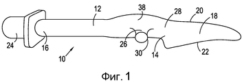
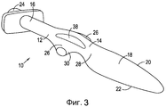
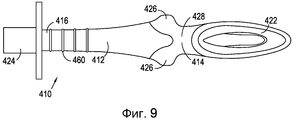
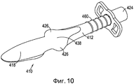
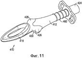
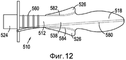
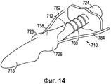
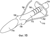
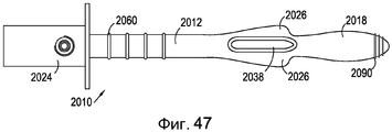
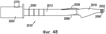
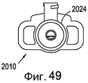
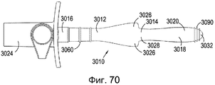
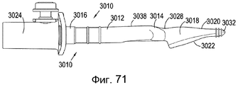
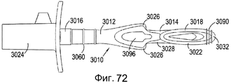
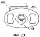
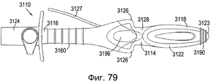
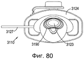
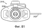
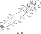
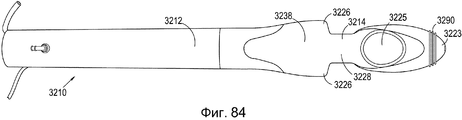
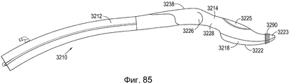
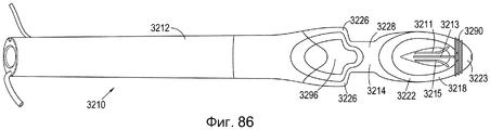
Согласно первому аспекту настоящего изобретения обеспечивается воздухопроводящее устройство для использования у людей и животных, при этом устройство включает в себя дыхательную трубку, имеющую первый конец и второй конец, причем устройство дополнительно включает в себя плечо, при этом плечо отходит в поперечном направлении от дыхательной трубки и выполнено с возможностью соприкосновения с дужками зева пациента - человека или животного - для недопущения чрезмерной вставки устройства при использовании. Это является особым преимуществом, поскольку обеспечивается воздухопроводящее устройство, которое имеет упор-ограничитель в виде плеча, которое выполнено или единым целым с устройством или отдельно от устройства, и которое помогает не допустить чрезмерной вставки воздухопроводящего устройства за пределы желаемого участка.According to a first aspect of the present invention, there is provided an air-conducting device for use in humans and animals, the device including a breathing tube having a first end and a second end, the device further including a shoulder, the shoulder extending laterally from the breathing tube and made with the possibility of contact with the arches of the throat of the patient - a person or an animal - to prevent excessive insertion of the device when used. This is a particular advantage because an air-conducting device is provided that has a shoulder stop that is either integral with the device or separate from the device, and which helps to prevent the air-conducting device from being excessively inserted outside the desired area.
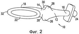
В одном альтернативном варианте первый конец дыхательной трубки окружен ларингеальной манжетой, причем ларингеальная манжета включает в себя задний спинной участок и передний лицевой участок, при этом передний лицевой участок ларингеальной манжеты имеет такую форму, чтобы образовывать анатомическое прилегание к входу в гортань пациента - человека или животного, и для изоляции входа в гортань пациента. В этом альтернативном варианте обеспечивается воздухопроводящее устройство, имеющее стопорный механизм в виде плеча, которое выполнено или единым целым с устройством или отдельно от устройства, и которое помогает не допустить чрезмерной вставки воздухопроводящего устройства за пределы входа в гортань пациента. Вставка воздухопроводящего устройства за пределы входа в гортань пациента может привести к серьезной травме трахеи и голосовых связок. Предпочтительно, ширина плеча больше ширины ларингеальной манжеты.In one alternative embodiment, the first end of the respiratory tube is surrounded by a laryngeal cuff, wherein the laryngeal cuff includes the posterior dorsal portion and the front facial portion, while the front facial portion of the laryngeal cuff is shaped to form an anatomical fit to the entrance to the larynx of the patient — human or animal , and to isolate the entrance to the larynx of the patient. In this alternative embodiment, an air-conducting device is provided having a locking mechanism in the form of a shoulder, which is made either integrally with the device or separately from the device, and which helps to prevent excessive insertion of the air-conducting device beyond the entrance to the patient's larynx. Inserting an air-conduction device beyond the patient’s larynx can result in serious injury to the trachea and vocal cords. Preferably, the shoulder width is greater than the width of the laryngeal cuff.
Во втором альтернативном варианте обеспечивается воздухопроводящее устройство для вставки в трахею или бронхи пациента - человека или животного, включающее в себя дыхательную трубку, имеющую первый конец и второй конец, манжету, расположенную на первом конце или вблизи первого конца дыхательной трубки, при этом манжета выполнена с возможностью зацепления стенки трахеи или бронхов при использовании. Для устройств, таких как эндотрахеальные трубки, плечи могут использоваться для облегчения определения того, когда устройство достигло максимальной длины вставки. Предпочтительно, ширина плеча больше ширины манжеты.In a second alternative embodiment, an air-conducting device is provided for insertion into the trachea or bronchi of a patient - a person or an animal, including a breathing tube having a first end and a second end, a cuff located at the first end or near the first end of the breathing tube, the cuff being made with the possibility of engaging the walls of the trachea or bronchi during use. For devices, such as endotracheal tubes, shoulders can be used to facilitate determining when the device has reached the maximum insertion length. Preferably, the shoulder width is greater than the width of the cuff.
Согласно другому альтернативному варианту, помимо недопущения чрезмерной вставки устройства, плечевой стопорный механизм остается непосредственно в контакте с дужками зева или в непосредственной близости от них, что также способствует и минимизации поворотного движения устройства и величине горизонтального и вертикального перемещения устройства после вставки. Именно место и ширина плеча в поперечном направлении относительно величины анатомического пространства вокруг дужек зева пациента, в сочетании друг с другом значительно ограничивают возможность перемещения устройства после вставки и не допускают случайного изменения вставленного устройства, которое может нарушить изоляцию. Плечо выполнено с возможностью создания контакта с дужками зева пациента - человека или животного - для недопущения чрезмерной вставки устройства при использовании. При создании контакта с дужками зева создается эффективный упор-ограничитель, который плечо не может переместить дальше, для обеспечения устройства, которое эффективно останавливает любую чрезмерную вставку, поскольку устройство просто не может переместиться за пределы требуемого участка.According to another alternative, in addition to preventing excessive insertion of the device, the shoulder locking mechanism remains directly in contact with the arches of the pharynx or in close proximity to them, which also contributes to minimizing the rotational movement of the device and the amount of horizontal and vertical movement of the device after insertion. It is the location and width of the shoulder in the transverse direction relative to the size of the anatomical space around the arches of the patient’s pharynx, in combination with each other that significantly limit the ability to move the device after insertion and prevent accidental changes to the inserted device, which may violate the insulation. The shoulder is configured to make contact with the arches of the pharynx of the patient - a person or an animal - to prevent excessive insertion of the device during use. When making contact with the arches of the pharynx, an effective stop-stop is created, which the shoulder cannot move further, to provide a device that effectively stops any excessive insertion, since the device simply can not move beyond the desired area.
Плечо может составлять единое целое с дыхательной трубкой или в альтернативном варианте оно может прикрепляться к дыхательной трубке с возможностью снятия. Случай, когда плечо составляет единое целое с дыхательной трубкой, является более подходящим в создании новых устройств, тогда как съемное плечо может быть более подходящим для обратной совместимости с существующими устройствами, или просто доустанавливаться на существующие устройства в проблемных ситуациях с пациентом, а также сниматься в случае, когда у пациента внутренние размеры сильно отличаются от ожидаемых. Настоящее изобретение, следовательно, не только включает в себя воздухопроводящие устройства, уже снабженные плечом, но также плечи, которые обратно совместимы с существующими воздухопроводящими устройствами.The shoulder may be integral with the breathing tube or, alternatively, it may be removably attached to the breathing tube. The case where the shoulder is integral with the breathing tube is more suitable in the creation of new devices, while the removable shoulder may be more suitable for backward compatibility with existing devices, or simply be mounted on existing devices in problem situations with the patient, as well as act in film when the patient's internal dimensions are very different from expected. The present invention, therefore, not only includes air conduction devices already provided with a shoulder, but also shoulders that are backward compatible with existing air conduction devices.
В одном альтернативном варианте плечо выполнено из материала с твердостью по Шору, составляющей 80 или менее по шкале A, более предпочтительно, 40 или менее по шкале А, еще более предпочтительно, 20 или менее по шкале A, и еще более предпочтительно, 10 или менее по шкале А, наиболее предпочтительно, 0 или менее по шкале А. Плечо может иметь твердость по Шору, лежащую в диапазоне от 80 до 000 включительно по шкале А, более предпочтительно, лежащую в диапазоне от 40 до 000 включительно по шкале А, еще более предпочтительно, лежащую в диапазоне от 20 до 000 включительно по шкале А, еще более предпочтительно, от 10 до 000 включительно по шкале А. Важно обеспечить устройство с более твердым плечом для использования, например, у лошадей, которые значительно крупнее и сильнее, чем собаки, кошки и кролики. Если в устройстве для лошадей используется мягкий материал, дыхательная трубка с большей вероятностью изогнется вместе с другими элементами воздухопроводящего устройства, что приведет к перекрыванию воздушных путей. Более твердый материал также важен для использования у более крупных животных, например, лошадей, поскольку длина устройства очень велика по сравнению с длиной устройства для других биологических видов. Это происходит потому, что расстояние между ротовым отверстием и входами в гортань и пищевод значительно больше, чем у многих других биологических видов, отчасти потому, что животное является значительно более крупным. Проблема состоит в том, что когда воздухопроводящее устройство увеличено до размера, который подходит для использования, например, у лошади, устройство более подвержено изгибу и перегибу, что может привести к перекрытию дыхательной трубки, если бы она была изготовлена из того же мягкого материала, какой используется для более мелких биологических видов. Таким образом, необходимо использовать более твердые материалы и для плеча и для дыхательной трубки для придания устройству большей устойчивости к перегибу для снижения вероятности того, что будет блокирован и перекрыт поток воздуха через воздушные пути.In one alternative embodiment, the shoulder is made of a material with Shore hardness of 80 or less on A, more preferably 40 or less on A, even more preferably 20 or less on A, and even more preferably 10 or less on a scale of A, most preferably 0 or less on a scale of A. The shoulder can have Shore hardness ranging from 80 to 000 inclusive on a scale A, more preferably lying in a range from 40 to 000 inclusive on a scale A, even more preferably ranging from 20 to 000 include tionary on a scale of A, even more preferably from 10 to 000 inclusive of the scale A. It is important to provide a device with a hard shoulder to be used, for example, in horses, which are much larger and stronger than dogs, cats and rabbits. If soft material is used in the horse device, the breathing tube is more likely to bend along with other elements of the air-conduction device, resulting in airway obstruction. A harder material is also important for use in larger animals, such as horses, since the length of the device is very long compared to the length of the device for other species. This is because the distance between the mouth opening and the entrances to the larynx and esophagus is significantly greater than that of many other species, in part because the animal is significantly larger. The problem is that when the air conduction device is enlarged to a size that is suitable for use, for example, in a horse, the device is more susceptible to bending and bending, which can lead to blockage of the breathing tube if it were made of the same soft material as used for smaller species. Thus, it is necessary to use harder materials for both the shoulder and the breathing tube to give the device more resistance to bending to reduce the likelihood that the air flow through the airways will be blocked and blocked.
В альтернативном варианте плечо может включать в себя жесткую сердцевину и более мягкое наружное покрытие или оболочку. В этом альтернативном варианте жесткая сердцевина может иметь твердость по Шору, лежащую в диапазоне 40-90 по шкале А, а более мягкое наружное покрытие может иметь твердость по Шору, лежащую в диапазоне 000-40 по шкале А.Alternatively, the shoulder may include a rigid core and a softer outer coating or sheath. In this alternative embodiment, the hard core may have a Shore hardness lying in the range 40-90 on the A scale, and a softer outer coating may have a Shore hardness lying in the range 000-40 on the A scale.
Плечо может быть выполнено из сплошного куска материала, имеющего однородную плотность по всему плечу. В альтернативном варианте плечо может быть полым, в этом альтернативном варианте плечо может иметь гибкую или жесткую оболочку, при этом плечо, имеющее гибкую оболочку, может быть предварительно заполнено воздухом или любой другой подходящей текучей средой. В дополнительном альтернативном варианте оболочка плеча может быть предварительно заполнена гелем или пеной.The shoulder can be made of a solid piece of material having a uniform density over the entire shoulder. Alternatively, the shoulder may be hollow, in this alternative, the shoulder may have a flexible or rigid shell, and the shoulder having a flexible shell may be pre-filled with air or any other suitable fluid. In a further alternative embodiment, the shoulder sheath may be pre-filled with gel or foam.
В альтернативном варианте плечо включает в себя надувную область. Надувная область может быть только частью плеча или, в альтернативном варианте, может располагаться по всей длине плеча.Alternatively, the shoulder includes an inflatable area. The inflatable area may be only part of the shoulder or, alternatively, may be located along the entire length of the shoulder.
В дополнительном альтернативном варианте плечо включает в себя ребро. В еще одном альтернативном варианте плечо включает в себя множество ребер. В этом альтернативном варианте плечо предпочтительно выполнено из материала, имеющего твердость по Шору, составляющую 80 или менее по шкале А, предпочтительно, 40 или менее по шкале А, более предпочтительно, 20 или менее по шкале А, еще более предпочтительно, 10 или менее по шкале A, наиболее предпочтительно 0 или менее по шкале А. Плечо может иметь твердость по Шору, лежащую в диапазоне от 80 до 000 включительно по шкале А, предпочтительно от 40 до 000 по шкале А, более предпочтительно, лежащую в диапазоне от 20 до 000 включительно по шкале А, еще более предпочтительно, лежащую в диапазоне от 10 до 000 включительно по шкале А.In a further alternative embodiment, the shoulder includes a rib. In yet another alternative embodiment, the shoulder includes many ribs. In this alternative embodiment, the shoulder is preferably made of a material having a Shore hardness of 80 or less on a scale A, preferably 40 or less on a scale A, more preferably 20 or less on a scale A, even more preferably 10 or less on A scale, most preferably 0 or less on A scale. The shoulder can have Shore hardness ranging from 80 to 000 inclusive on A scale, preferably from 40 to 000 on A scale, more preferably lying in the range from 20 to 000 inclusive on A scale, even more respectfully, ranging from 10 to 000 inclusive on scale A.
Независимо от того, выполнено плечо из мягкого материала, жесткой сердцевины с покрытием из мягкого материала, с надувной областью, ребром или множеством ребер, плечо должно быть мягким для минимизации любой травмы окружающих тканей при вставке устройства, в особенности дужек зева и окружающих тканей. Ширина плеча должна быть больше ширины дужек зева, но меньше внутренней ширины задней части полости рта для создания надежного стопорного элемента, обеспечения вставки устройства в правильное положение, и отсутствия трения о внутреннюю сторону полости рта, что может вызвать раздражение при использовании. Кроме того, форма плеча должна быть идеально приближена к перпендикуляру к направлению дыхательной трубки для создания максимального сопротивлению стремлению плеча преодолеть упругость тканей дужек зева. Угол наклона ведущей поверхности плеча предпочтительно составляет ±15° к перпендикуляру к дыхательной трубке. Выполнение плеча из мягкого или надуваемого материала предназначено для уменьшения любой возможной травмы, которая может возникнуть при внезапном контакте плеча воздухопроводящего устройства с дужками зева, для обеспечения свойства упора-ограничителя. При вставке воздухопроводящего устройства плечо будет, в конечном счете, ударять по дужкам зева и будет естественно отскакивать и останется на удалении от непосредственного контакта со структурами дужек зева, таким образом, не вызывая никакой травмы. Небольшой вертикальный наклон переднего края плеча в некоторых вариантах осуществления гарантирует минимизацию площади поверхности возможного контакта и исключение травматизации структур дужек зева.Regardless of whether the shoulder is made of soft material, a rigid core coated with soft material, with an inflatable region, a rib or many ribs, the shoulder should be soft to minimize any trauma to surrounding tissues when inserting the device, especially the arches of the pharynx and surrounding tissues. The width of the shoulder should be greater than the width of the arches of the pharynx, but less than the internal width of the back of the oral cavity to create a reliable locking element, to ensure that the device is inserted into the correct position, and there is no friction on the inside of the oral cavity, which can cause irritation during use. In addition, the shape of the shoulder should be ideally close to the perpendicular to the direction of the breathing tube to create maximum resistance to the desire of the shoulder to overcome the elasticity of the tissues of the arches of the pharynx. The angle of inclination of the leading surface of the shoulder is preferably ± 15 ° to the perpendicular to the breathing tube. The implementation of the shoulder of a soft or inflatable material is intended to reduce any possible injury that may occur when the shoulder of the air-conducting device suddenly contacts the arches of the throat, to ensure the properties of the stop-limiter. When an air-conducting device is inserted, the shoulder will ultimately hit the arches of the pharynx and will naturally bounce and stay away from direct contact with the structures of the pharyngeal arches, thus causing no injury. A small vertical inclination of the front edge of the shoulder in some embodiments ensures minimizing the surface area of possible contact and eliminating trauma to the structures of the arches of the pharynx.
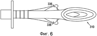
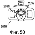
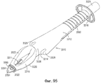
Плечо выполнено для создания упора-ограничителя у дужек зева пациента - человека или животного - благодаря размеру, значительно превышающему расстояние между дужками зева. Некоторые из устройств предшествующего уровня техники имеют стабилизатор щечных полостей, этот элемент, однако, не создает упора-ограничителя, поскольку стабилизатор щечных полостей только немного больше дужек зева. Более того, плавные очертания стабилизатора щечных полостей в устройствах предшествующего уровня техники на самом деле действует на увеличение расстояния между эластичными тканями дужек зева. Это растягивание дужек зева приводит к чрезмерной вставке устройства и может привести к описанной выше травме. Таким образом, предпочтительным является плечо, которое не только шире дужек зева, но также у которого ведущая поверхность или край плеча по существу перпендикулярен дыхательной трубке и, таким образом, по существу параллелен контактной поверхности дужек зева для создания упора-ограничителя.The shoulder is made to create a stop-limiter at the arches of the pharynx of the patient - a person or an animal - due to the size significantly exceeding the distance between the arches of the pharynx. Some of the devices of the prior art have a buccal cavity stabilizer; this element, however, does not create a stop-limiter, since the buccal cavity stabilizer is only slightly larger than the arches of the pharynx. Moreover, the smooth outlines of the stabilizer of the buccal cavities in prior art devices actually act to increase the distance between the elastic tissues of the arches of the pharynx. This stretching of the arches of the pharynx leads to excessive insertion of the device and can lead to the injury described above. Thus, a shoulder is preferred, which is not only wider than the arches of the pharynx, but also whose leading surface or edge of the shoulder is essentially perpendicular to the respiratory tube and thus substantially parallel to the contact surface of the pharyngeal arches to create a stop-stop.
Кроме того, для некоторых биологических видов плечо может быть снабжено обращенными вперед выступами. Обращенные вперед выступы располагаются на ведущей поверхности плеча. Обращенные вперед выступы выполнены с возможностью расположения в анатомических полостях, которые имеются у собак, например, позади глоточных дужек. В целом, большинство пород собак имеют очень широкую глоточную дужку, поскольку для собак характерно очень быстрое потребление больших объемов пищи. Тот факт, что глоточная дужка существенно шире у собак, чем таковая у других биологических видов, может приводить к тому, что воздухопроводящее устройство не прилегает так плотно к глоточной дужке, как может потребоваться в практической деятельности и, таким образом, чтобы минимизировать любой риск прохождения плеча за пределы требуемого положения, плечо может быть снабжено описанными выше обращенными вперед выступами. Обращенные вперед выступы выполнены для вставки в области, имеющие анатомические полости, чтобы сделать все воздухопроводящее устройство более надежно закрепленным и нелегко обходящим глоточные дужки. Имеет смысл принять во внимание, что глоточные дужки у собак являются особенно эластичными. Обращенные вперед выступы более предпочтительно, приводят к формированию обращенных вперед зазубрин или полостей. Предпочтительны полости U или V- образной формы и выполненные с возможностью соответствия тонким выступающим глоточным дужкам, например, у собак. Наиболее предпочтительно, U-образные или V-образные полости взаимозацепляются с глоточными дужками для удержания устройства на месте.In addition, for some species, the shoulder may be provided with forward projections. The forward projections are located on the leading surface of the shoulder. The forward projections are arranged to be located in the anatomical cavities that are present in dogs, for example, behind the pharyngeal arches. In general, most dog breeds have a very wide pharyngeal arch, since dogs are characterized by very fast consumption of large amounts of food. The fact that the pharyngeal arch is significantly wider in dogs than that of other species, can lead to the fact that the air-conduction device does not fit as close to the pharyngeal arch as may be required in practice and, thus, to minimize any risk of passage shoulder beyond the desired position, the shoulder may be provided with the above facing projections. The forward-facing protrusions are made for insertion into areas having anatomical cavities in order to make the entire air-conveying device more securely attached and not easily bypassing the pharyngeal arches. It makes sense to take into account that the pharyngeal arches in dogs are especially resilient. The forward facing protrusions more preferably result in the formation of forward notches or cavities. Preferred cavities are U or V-shaped and configured to fit thin protruding pharyngeal arches, for example, in dogs. Most preferably, the U-shaped or V-shaped cavities are interlocked with the pharyngeal arches to hold the device in place.
Плечо обеспечивает то, что небольшие манжеты на воздухопроводящих устройствах будут оставаться в правильном положении в гортани пациента и не пройдут за пределы требуемого положения, которое в противном случае вызовет повреждение пациента. Плечо действует намного более эффективно для установки устройства в правильном положении, чем при использовании только кончика манжеты ларингеальной маски для определения величины вставки и недопущения чрезмерной вставки, поскольку у некоторых биологических видов структуры пищевода могут быть более эластичными по природе, чем у других видов, и могут, следовательно, быть более податливыми. Эта податливость позволяет продвинуть устройство дальше за пределы идеального изолирующего положения для эффективного использования воздухопроводящего устройства.The shoulder ensures that the small cuffs on the air-conducting devices will remain in the correct position in the patient's larynx and will not go beyond the desired position, which would otherwise cause damage to the patient. The shoulder acts much more efficiently in placing the device in the correct position than using only the tip of the cuff of the laryngeal mask to determine the size of the insert and prevent excessive insertion, since in some biological species the structure of the esophagus may be more elastic in nature than in other species, and may therefore be more malleable. This flexibility allows the device to be moved further beyond the ideal insulating position for efficient use of the air-conducting device.
Другое преимущество плеча состоит в том, что оно препятствует повороту воздухопроводящего устройства, поскольку оно устанавливается более эффективно в области языка, расположенной в задней части рта. Это создает большее сопротивление повороту, поскольку объем в задней части рта становится ограниченным. Использование необязательной расширенной области от плеча назад в направлении трубчатой секции дыхательной трубки для создания экрана может также использоваться для создания поверхностного контакта с передней поверхностью языка для незначительного увеличения сопротивления повороту воздухопроводящего устройства. Расширение не является обязательным условием для стопорной функции плеча, но обеспечивает более эффективное сопротивление перемещению, используя иной участок рта пациента.Another advantage of the shoulder is that it prevents the rotation of the air-conducting device, since it is installed more efficiently in the area of the tongue located in the back of the mouth. This creates greater turning resistance as the volume in the back of the mouth becomes limited. Using the optional extended area from the shoulder backward towards the tubular section of the breathing tube to create a screen can also be used to create surface contact with the front surface of the tongue to slightly increase the rotation resistance of the air-conducting device. Expansion is not a prerequisite for the stop function of the shoulder, but provides a more effective resistance to movement, using a different part of the patient's mouth.
Имеет смысл помнить, что для эффективности плеча этот элемент не должен быть выполнен из "мягкого" материала, например, имеющего твердость по Шору, составляющую 80 или менее по шкале А. В альтернативном варианте плечо может быть изготовлено из очень твердого жесткого материала, например, очень твердого жесткого пластического материала. Если плечо изготовлено из очень твердого жесткого пластического материала, плечо по-прежнему не допускает слишком далекой вставки воздухопроводящего устройства пациенту - человеку или животному - и способствует недопущению нежелательного поворота воздухопроводящего устройства. Однако при использовании очень твердых жестких пластических материалов может случиться некоторая травма, когда жесткий пластический материал приходит в контакт с пациентом. Таким образом, предпочтителен более мягкий материал, но это не значит, что твердые материалы неэффективны. Если используется жесткий пластический материал, он может быть дополнительно покрыт мягким материалом.It makes sense to remember that for shoulder effectiveness this element should not be made of a “soft” material, for example, having a Shore hardness of 80 or less on scale A. Alternatively, the shoulder can be made of a very hard hard material, for example, very hard hard plastic material. If the shoulder is made of a very hard, hard plastic material, the shoulder still prevents the patient from introducing the air-conducting device too far - a person or an animal - and helps to prevent unwanted rotation of the air-carrying device. However, when using very hard rigid plastic materials, some injury may occur when the hard plastic material comes into contact with the patient. Thus, a softer material is preferred, but this does not mean that hard materials are ineffective. If a hard plastic material is used, it may be further coated with a soft material.
Предпочтительно, плечо дополнительно включает в себя один или более вытяжных каналов. Вытяжные каналы обеспечиваются для облегчения удаления текучих сред, которые могут накапливаться в задней части рта. Воздухопроводящее устройство может также быть снабжено пищеводно-желудочным каналом. Вытяжные каналы могут составлять единое целое с пищеводно-желудочным каналом или быть отдельными от пищеводно-желудочного канала, если таковой имеется. В дополнительном альтернативном варианте воздухопроводящее устройство может просто быть снабжено пищеводно-желудочным каналом.Preferably, the shoulder further includes one or more exhaust ducts. Exhaust ducts are provided to facilitate removal of fluids that may accumulate in the back of the mouth. The airway device may also be provided with an esophageal and gastric canal. Exhaust canals can be integral with the esophageal-gastric canal or be separate from the esophageal-gastric canal, if any. In a further alternative embodiment, the air-conducting device may simply be provided with an esophageal-gastric canal.
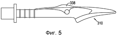
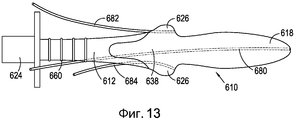
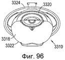
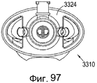
Предпочтительно, обеспечивается приподнятый участок на заднем спинном участке дыхательной трубки. Предпочтительно, приподнятый участок выполнен с возможностью соприкосновения при использовании с небно-язычной дужкой пациента - человека или животного. Приподнятый участок представляет собой, предпочтительно, мягкую область на дыхательной трубке дистальнее манжеты, над плечом, выполненная с возможностью быть обращенной в направлении полости верхней дужки рта и быть расположенной в ней (небно-язычная дужка) при использовании. Этот приподнятый участок создает два больших преимущества; первое состоит в том, что его высота и передняя область натолкнется на область верхней дужки пациента, если врач попытается чрезмерно вставить устройство. Также, например, если устройство перекручено на соединительном конце устройства, стороны приподнятого участка будут наталкиваться на стороны полости верхней дуги пациента, так что оно очень быстро достигает точки, которая ограничивает любое дополнительное поворотное движение и, следовательно, будет предохранять устройство от поворота и не приведет к смещению воздухопроводящего устройства из оптимального изолирующего положения в воздухопроводящем пути пациента. Приподнятый участок также значительно ограничивает любое перемещение вверх и вниз при приложении усилия, и в сторону, или боковое, движение воздухопроводящего устройства, следовательно, он значительно ограничивает устройство, так что оно остается в правильном положении после того, как правильно вставлено, и на протяжении клинического использования.Preferably, a raised portion is provided in the posterior dorsal portion of the breathing tube. Preferably, the raised portion is adapted to be contacted when used with a palatine-lingual arch of a patient — a human or animal. The raised portion is preferably a soft region on the breathing tube distal to the cuff, over the shoulder, configured to face the cavity of the upper arch of the mouth and be located therein (palatine-tongue arch) when used. This elevated area provides two great advantages; the first is that its height and front region will come across the region of the patient’s upper arch if the doctor tries to over-insert the device. Also, for example, if the device is twisted at the connecting end of the device, the sides of the raised portion will collide with the sides of the cavity of the patient’s upper arc, so that it very quickly reaches a point that limits any additional pivotal movement and, therefore, will prevent the device from turning and will not cause to displace the air-conducting device from the optimal insulating position in the air-conducting path of the patient. The raised portion also significantly limits any movement up and down when applying force, and to the side, or lateral, movement of the air-conducting device, therefore, it significantly limits the device so that it remains in the correct position after being inserted correctly, and throughout the clinical use.
Приподнятый участок может быть суженным, чтобы обеспечить некоторым биологическим видам недопущение любого возможного контакта, который может иметь место с зубами пациента.The elevated area may be narrowed to allow certain species to prevent any possible contact that may occur with the patient’s teeth.
Когда приподнятый участок включает в себя выпуклость, она, предпочтительно, выполнена из материала, имеющего твердость по Шору, лежащую в диапазоне 80 или менее по шкале А, более предпочтительно, выполненную из материала, имеющего твердость по Шору, лежащую в диапазоне 40 или менее по шкале А, еще более предпочтительно, 20 или менее по шкале А, и еще более предпочтительно, 10 или менее по шкале А, наиболее предпочтительно, 0 или менее по шкале А. Приподнятый участок может иметь твердость по Шору, лежащую в диапазоне 80-000 включительно по шкале А, более предпочтительно, лежащую в диапазоне 40-000 включительно по шкале А, еще более предпочтительно, лежащую в диапазоне 20-000 включительно по шкале А, и еще более предпочтительно, 10-000 включительно по шкале А. Важно обеспечить устройства с более жестким приподнятым участок для использования, например, у лошадей, которые являются значительно более крупными и сильными животными, чем собаки, кошки и кролики. Если в устройстве для лошадей используется мягкий материал, более вероятно выгибание, которое приводит к перекрыванию потока воздуха. Более твердый материал также важен для использования у более крупных лошадей, поскольку длина устройства является очень большой по сравнению с другими биологическими видами. Это происходит потому, что расстояние между ротовым отверстием и входом в гортань и пищевод значительно больше, чем у многих других биологических видов, отчасти потому, что лошади значительно крупнее. Проблема состоит в том, что когда воздухопроводящее устройство увеличено до размера, который будет подходящим для использования, например, у лошадей, устройство более склонно к изгибанию и выгибанию, которые могут привести к перекрыванию дыхательной трубки, если она была выполнена из такого же мягкого материала, как используемая для более мелких биологических видов. Таким образом, необходимо использование более твердых материалов и для приподнятого участка, и для дыхательной трубки, для придания большей устойчивости к выгибанию устройства для снижения риска того, что путь прохождения воздуха будет блокирован и будет перекрыт поток воздуха.When the raised portion includes a bulge, it is preferably made of a material having a shore hardness lying in the range of 80 or less on a scale A, more preferably made of a material having a shore hardness lying in the range of 40 or less scale A, even more preferably 20 or less on scale A, and even more preferably 10 or less on scale A, most preferably 0 or less on scale A. The raised portion may have shore hardness ranging from 80-000 inclusive on A scale, more preferably lying in the range of 40-000 inclusive on the scale A, even more preferably lying in the range of 20-000 inclusive on the scale A, and even more preferably 10-000 inclusive on the scale A. It is important to provide devices with a stiffer raised section for use, for example, in horses, which are significantly larger and stronger animals than dogs, cats and rabbits. If soft material is used in the horse device, bending is more likely to result in airflow obstruction. A harder material is also important for use with larger horses, as the length of the device is very large compared to other species. This is because the distance between the mouth opening and the entrance to the larynx and esophagus is significantly greater than that of many other species, in part because the horses are much larger. The problem is that when the air-conducting device is enlarged to a size that is suitable for use, for example, in horses, the device is more prone to bending and bending, which can lead to blockage of the breathing tube if it was made of the same soft material, as used for smaller species. Thus, it is necessary to use harder materials for both the elevated area and the breathing tube to give greater resistance to bending of the device to reduce the risk that the air path will be blocked and the air flow will be blocked.
В альтернативном варианте приподнятый участок может включать в себя жесткую сердцевину, имеющую более мягкое наружное покрытие или оболочку. В этом альтернативном варианте жесткая сердцевина может иметь твердость по Шору, лежащую в диапазоне 40-90 включительно по шкале А, а более мягкое наружное покрытие может иметь твердость по Шору, лежащую в диапазоне 000-40 включительно по шкале А.Alternatively, the raised portion may include a rigid core having a softer outer coating or sheath. In this alternative embodiment, the hard core may have a Shore hardness lying in the range 40-90 inclusive on the A scale, and a softer outer coating may have a Shore hardness lying in the range 000-40 inclusive on the A scale.
В дополнение к этому, или в альтернативном варианте, когда приподнятый участок включает в себя множество ребер, они предпочтительно выполнены из материала, имеющего твердость по Шору, лежащую в диапазоне 80 или менее по шкале А, предпочтительно, 40 или менее по шкале А, более предпочтительно, 20 или менее по шкале А, еще более предпочтительно, 10 или менее по шкале A, наиболее предпочтительно, 0 или менее по шкале А. Приподнятый участок может иметь твердость по Шору, лежащую в диапазоне 80-000 включительно по шкале А, предпочтительно, 40-000 по шкале А, более предпочтительно, лежащую в диапазоне 20-000 включительно по шкале А, еще более предпочтительно, лежащую в диапазоне 10-000 включительно по шкале А.In addition to this, or alternatively, when the raised portion includes a plurality of ribs, they are preferably made of a material having a Shore hardness lying in the range of 80 or less on the scale A, preferably 40 or less on the scale A, more preferably 20 or less on scale A, even more preferably 10 or less on scale A, most preferably 0 or less on scale A. The raised portion may have shore hardness ranging from 80-000 inclusive on scale A, preferably , 40-000 on a scale A, bol it is preferably lying in a range of 20-000 inclusive on a scale A, even more preferably lying in a range of 10-000 inclusive on a scale A.
Приподнятый участок может быть выполнен в виде множества конфигураций: например, но без ограничения, сплошного мягкого материала, имеющего диапазон твердости по Шору, составляющий 000-80 по шкале А, или выполненная из повторяющихся конфигураций сетчатого или ребристого типа, обладающих одинаковой формой аналогичной твердости, или вплоть до твердости по Шору, составляющей 80 по шкале А, или из внутренней сердцевины, изготовленной из более твердого материала с твердостью по Шору, лежащей в диапазоне 80-000 по шкале А, и наружного покрытия или оболочки, изготовленной из более мягкого материала с твердостью по Шору, составляющей 40-000 по шкале А. Этот приподнятый участок сам по себе и вместе с плечом значительно ограничивает поворотные, боковые, поперечные и рычажные перемещения устройства и в значительной степени защищает воздухопроводящее устройство от чрезмерной вставки, поворота или рычажного перемещения из оптимального изолирующего положения. Кроме того, или в альтернативном варианте, приподнятый участок может включать в себя надувную область. Надувная область может быть просто частью приподнятого участка, или в альтернативном варианте может составлять весь приподнятый участок.The raised portion can be made in the form of many configurations: for example, but without limitation, a continuous soft material having a Shore hardness range of 000-80 on a scale A, or made of repeating mesh or ribbed configurations having the same shape of similar hardness, or up to Shore hardness of 80 on A scale, or from an inner core made of harder material with Shore hardness in the range of 80-000 on A scale, and an outer coating or coating glasses made of a softer material with a Shore hardness of 40-000 on a scale A. This raised section by itself and together with the shoulder significantly limits the rotary, lateral, lateral and lever movements of the device and significantly protects the air-conduction device from excessive insertion, rotation or lever movement from the optimum insulating position. In addition, or alternatively, the raised portion may include an inflatable area. The inflatable area may simply be part of the raised portion, or alternatively may comprise the entire raised portion.
Приподнятый участок может быть выполнен из сплошного материала, имеющего однородную плотность по всему приподнятому участку. В альтернативном варианте приподнятый участок может быть полым, в этом альтернативном варианте приподнятый участок может иметь гибкую или жесткую оболочку, при этом если приподнятый участок имеет гибкую оболочку, он может быть предварительно заполнен воздухом или любой другой подходящей текучей средой. В дополнительном альтернативном варианте оболочка приподнятого участка может быть предварительно заполнена гелем или пеной.The raised portion may be made of a continuous material having a uniform density throughout the raised portion. Alternatively, the raised portion may be hollow; in this alternative, the raised portion may have a flexible or rigid shell, and if the raised portion has a flexible shell, it may be pre-filled with air or any other suitable fluid. In a further alternative embodiment, the shell of the raised portion may be pre-filled with gel or foam.
Эти усовершенствования увеличивают безопасность использования и для опытных, и для неопытных пользователей воздухопроводящих устройств посредством значительного уменьшения потенциальных опасностей, связанных со вставкой вслепую различных видов воздухопроводящих устройств пациентам. Эти усовершенствования обеспечиваются для устройства, которое предназначено вставляться в анатомическое образование и которое будет правильно вставлено и не будет крутиться или выскакивать после вставки.These enhancements increase the safety of use for both experienced and inexperienced users of air-conduction devices by significantly reducing the potential dangers associated with blindly inserting various types of air-conduction devices to patients. These improvements are provided for a device that is intended to be inserted into the anatomical formation and which will be correctly inserted and will not spin or pop up after insertion.
Следует пояснить, что хотя на всех чертежах, как правило, присутствуют и элементы плечевого участка и элементы приподнятого участка, наличие приподнятого участка на воздухопроводящем устройстве не является существенным для изобретения, и воздухопроводящее устройство может просто иметь элемент плеча. Приподнятый участок не является обязательным для работы плеча, он просто обеспечивает дополнительную надежность.It should be clarified that although all the drawings, as a rule, contain elements of the shoulder portion and elements of the raised portion, the presence of the raised portion on the air-conducting device is not essential for the invention, and the air-conducting device may simply have a shoulder element. The raised portion is not required for shoulder operation; it merely provides additional reliability.
Следует заметить, что воздухопроводящее устройство, включающее в себя манжету, плечо и приподнятый участок (где он имеется) предпочтительно выполнено из полимерного или другого пластического материала. Подразумевается, что такие полимерные материалы включают в себя термоотверждаемые каучуки, например, силикон, натуральный каучук, неопрен и полиуретаны.It should be noted that the air-conducting device, including the cuff, the shoulder and the raised portion (where available) is preferably made of a polymer or other plastic material. It is understood that such polymeric materials include thermoset rubbers, for example, silicone, natural rubber, neoprene and polyurethanes.
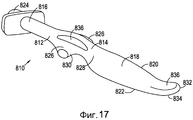
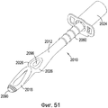
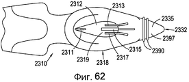
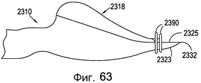
В описанном выше альтернативном варианте, в котором первый конец дыхательной трубки окружен ларингеальной манжетой, в одном альтернативном варианте ларингеальная манжета имеет кончик, при этом кончик наклонен в направлении заднего спинного участка ларингеальной манжеты. Предпочтительно, кончик наклонен под углом от 5° до 80° включительно к горизонтальной плоскости ларингеальной манжеты. Такой наклон имеет эффект, заключающийся в увеличении площади поверхности кончика, поскольку большая его часть зацепляется с пищеводом, таким образом, это создает высокий уровень зацепления и изоляции пищевода, и, следовательно, другую форму сопротивления чрезмерной вставке воздухопроводящего устройства, по сравнению со случаем, когда кончик является узким и более прямым. Кончик может иметь задний спинной участок и передний лицевой участок, при этом задний спинной участок в основном выполнен из более твердого материала, нежели передний лицевой участок, с тем, чтобы придать кончику прочность к складыванию, а очень мягкая нижняя сторона значительно уменьшает возможность повреждения пищевода.In the alternative embodiment described above, in which the first end of the respiratory tube is surrounded by a laryngeal cuff, in one alternative embodiment, the laryngeal cuff has a tip, with the tip inclined toward the posterior dorsal portion of the laryngeal cuff. Preferably, the tip is inclined at an angle of 5 ° to 80 ° inclusive to the horizontal plane of the laryngeal cuff. Such a slope has the effect of increasing the tip's surface area, since most of it engages with the esophagus, thus creating a high level of engagement and isolation of the esophagus, and therefore a different form of resistance to over-insertion of the air-conduction device compared to when the tip is narrower and more straight. The tip may have a posterior dorsal portion and anterior facial portion, with the posterior dorsal portion generally made of a harder material than the front facial portion, so as to give the tip folding strength, and a very soft underside significantly reduces the possibility of damage to the esophagus.
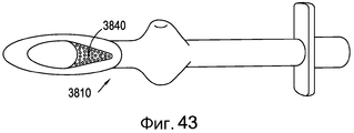
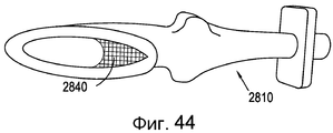
В дополнительном альтернативном варианте, в котором первый конец дыхательной трубки окружен ларингеальной манжетой, в одном альтернативном варианте ларингеальная манжета имеет кончик, при этом кончик включает в себя кольцевой фланцевый изолирующий участок, который может включать в себя множество кольцевых фланцевых изолирующих участков, при этом кольцевой фланцевый изолирующий участок выполнен с возможностью вклиниваться в верхнюю область пищевода пациента - человека или животного. Кольцевые фланцевые изолирующие участки обеспечиваются для улучшенной изоляции кончика ларингеальной манжеты в верхней области пищевода пациента - человека или животного. Кольцевые фланцевые изолирующие участки предпочтительно выполнены из мягкого полимерного или другого пластического материала, имеющего твердость по Шору, лежащую в диапазоне 40-000 по шкале А. Кольцевые фланцевые изолирующие участки обеспечивают лучшую изоляцию для более широкого диапазона анатомических особенностей верхней части пищевода.In a further alternative embodiment, in which the first end of the breathing tube is surrounded by a laryngeal cuff, in one alternative embodiment, the laryngeal cuff has a tip, the tip including an annular flange insulating portion, which may include a plurality of annular flange insulating portions, wherein the annular flange the insulating section is configured to wedge into the upper region of the esophagus of the patient - a person or an animal. Annular flange insulating sections are provided for improved isolation of the tip of the laryngeal cuff in the upper region of the patient’s esophagus - a human or animal. The annular flange insulating portions are preferably made of soft polymeric or other plastic material having a shore hardness ranging from 40-000 on scale A. The annular flange insulating portions provide better insulation for a wider range of anatomical features of the upper esophagus.
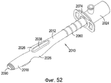
В еще одном дополнительном альтернативном варианте, в котором первый конец дыхательной трубки окружен ларингеальной манжетой, в одном альтернативном варианте ларингеальная манжета имеет кончик, при этом кончик лопаткоподобную форму для манипулирования надгортанником пациента. Кончик может иметь рельефную поверхность на заднем спинном участке манжеты и по существу плоскую поверхность на переднем лицевом участке манжеты. Такая особая форма конструкции позволяет врачу одним движением отвести надгортанник пациента - человека или животного - одновременно со вставкой воздухопроводящего устройства. Необходимо до или во время вставки воздухопроводящего устройства передвинуть надгортанник животных, например, собак, которые имеют очень большой и гибкий надгортанник по сравнению с некоторыми другими биологическими видами, чтобы способствовать недопущению прогибания, приводящего к перекрыванию пути прохода воздуха и, следовательно, воздушного потока, к пациенту. В одном альтернативном варианте кончик может иметь такой же рельеф, как спинной участок манжеты, или, в альтернативном варианте, может иметь дополнительный рельеф, чтобы глубина кончика уменьшалась по существу так, что он истончался до лопаткоподобного кончика.In yet a further alternative embodiment, in which the first end of the breathing tube is surrounded by a laryngeal cuff, in one alternative embodiment, the laryngeal cuff has a tip, while the tip has a scapular shape for manipulating the patient's epiglottis. The tip may have a raised surface on the posterior dorsal portion of the cuff and a substantially flat surface on the front facial portion of the cuff. Such a special form of construction allows the doctor to remove the patient’s epiglottis - a person or an animal - with the insertion of an air-conducting device in one motion. It is necessary to move the epiglottis of animals, for example, dogs, which have a very large and flexible epiglottis compared to some other species, before or during the insertion of the air-conduction device, in order to prevent bending, which leads to blocking the air passage and, therefore, the air flow, to the patient. In one alternative embodiment, the tip may have the same relief as the dorsal portion of the cuff, or, in the alternative embodiment, may have an additional relief so that the depth of the tip is reduced substantially so that it is thinned to a shoulder-like tip.
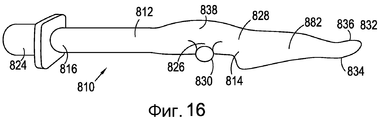
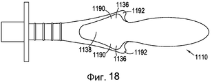
В дополнительном альтернативном варианте дыхательная трубка имеет вогнутый участок. Предпочтительно, вогнутый участок выполнен с возможностью контакта с выпуклым участком спинки языка пациента - человека или животного. При приложении давления к языку может возникнуть сжатие кровеносных сосудов языка, которое приводит к состоянию, известному как «синий язык». Для уменьшения любого давления, которое может иным образом прилагаться к спинке языка, может обеспечиваться вогнутый участок, чтобы давление не прикладывалось в этой области. Вогнутый участок в одном альтернативном варианте может представлять собой единственную вогнутую область, или в альтернативном варианте может представлять собой множество вогнутых областей, которые могут образовываться из совокупности углублений или ямок или, в альтернативном варианте, из совокупности бугорков или выступов. Кроме того, в альтернативном варианте вогнутый участок может представлять собой множество вогнутых областей, выполненных в виде последовательности бороздок или канавок, проходящих горизонтально или вертикально вдоль нижней стороны устройства, или дополнительно, в альтернативном варианте, быть выполнены в виде последовательности концентрических колец. Вогнутый участок не только действует на уменьшение давления, но также придает устойчивость местоположению устройства, установленному пациенту - человеку или животному.In a further alternative embodiment, the breathing tube has a concave portion. Preferably, the concave portion is configured to contact a convex portion of the back of the patient’s tongue — a human or animal. When pressure is applied to the tongue, compression of the blood vessels of the tongue can occur, which leads to a condition known as the “blue tongue”. To reduce any pressure that may otherwise be applied to the back of the tongue, a concave portion may be provided so that pressure is not applied in this area. The concave portion in one alternative embodiment may be a single concave region, or alternatively, may be a plurality of concave regions that may be formed from a plurality of recesses or pits or, alternatively, a plurality of tubercles or protrusions. In addition, in an alternative embodiment, the concave portion may be a plurality of concave regions made in the form of a sequence of grooves or grooves extending horizontally or vertically along the lower side of the device, or additionally, alternatively, be made in the form of a sequence of concentric rings. The concave portion not only acts to reduce the pressure, but also gives stability to the location of the device installed by the patient - a person or an animal.
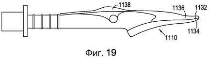
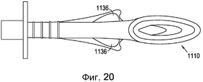
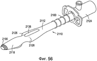
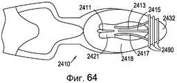
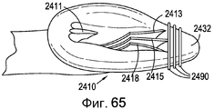
В дополнительном альтернативном варианте первый конец дыхательной трубки включает в себя перфорированную пластину или сетку, выполненную с возможностью недопущения прогибания надгортанника пациента - человека или животного - внутрь дыхательной трубки при использовании. По-прежнему существует беспокойство, что надгортанник прогнется в дыхательную трубку, что приведет к блокированию потока газов к пациенту и от пациента. Один путь увеличения безопасности состоит в наложении сетки или перфорированной пластины между верхней и нижней областями ларингеальной манжеты, чтобы сетка или перфорированная пластина располагались под поверхностью, используемой для изоляции, но достаточно высоко, чтобы препятствовать перекрытию пути прохождения воздуха из-за прогибания надгортанника в дыхательную трубку.In a further alternative embodiment, the first end of the breathing tube includes a perforated plate or mesh configured to prevent the patient’s epiglottis, a human or animal, from bending inside the breathing tube when used. There is still concern that the epiglottis will bend into the breathing tube, which will block the flow of gases to and from the patient. One way to increase safety is to lay a mesh or perforated plate between the upper and lower regions of the laryngeal cuff so that the mesh or perforated plate is below the surface used for insulation, but high enough to prevent the airway from blocking due to the bending of the epiglottis into the breathing tube .
В дополнительном альтернативном варианте для недопущения прогибания надгортанника и перекрытия пути воздуха может обеспечиваться скобка, или множество скобок, проходящих частично или полностью через проем манжеты или от проема дистального конца, или проема проксимального конца, или обоих. Скобка(и) не только не допускают перекрытия пути прохождения воздуха, но также придают прочность манжете. В одном альтернативном варианте скобка(и) может проходить от проема проксимального конца, в другом альтернативном варианте - от проема дистального конца, в другом альтернативном варианте скобка(и) могут проходить по всей длине проема. Скобка(и) могут просто проходить через проем, или в альтернативном варианте могут занимать всю высоту проема и контактировать с задней стороной проема. Скобка(и) может быть дополнительно снабжена выемками или вырезами на своей передней лицевой поверхности, так, что в случае, когда надгортанник ложится на скобку(и), поток воздуха между скобкой(ами) не затрагивается, так что не возникает эффектов турбулентности. Предпочтительно, скобка(и) выполнены из по существу жесткого материала, чтобы они удерживали вес надгортанника, а не прогибались под ним, что может привести к перекрытию пути прохождения воздуха, если скобка(и) изогнется под весом надгортанника. В дополнительном альтернативном варианте в области дистального проема манжеты может обеспечиваться участок твердого пластического материала для упрочнения кончика манжеты и для работы по направлению потока.In a further alternative, in order to prevent the epiglottis from bending and blocking the air path, a bracket or multiple brackets extending partially or completely through the opening of the cuff or from the opening of the distal end, or the opening of the proximal end, or both, can be provided. The bracket (s) not only prevent the air path from overlapping, but also give strength to the cuff. In one alternative embodiment, the bracket (s) may extend from the opening of the proximal end, in another alternative embodiment, from the opening of the distal end, in another alternative embodiment, the bracket (s) may extend along the entire length of the opening. The bracket (s) may simply pass through the opening, or alternatively may occupy the entire height of the opening and contact the rear side of the opening. The bracket (s) can be further provided with recesses or cutouts on its front face, so that when the epiglottis rests on the bracket (s), the air flow between the bracket (s) is not affected, so that there are no turbulence effects. Preferably, the bracket (s) are made of essentially rigid material so that they support the weight of the epiglottis, and not bend under it, which can lead to blocking the air passage if the bracket (s) bends under the weight of the epiglottis. In a further alternative, a region of solid plastic material may be provided in the region of the distal cuff opening to strengthen the cuff tip and to work in the direction of flow.
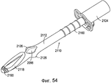
В дополнительном альтернативном варианте воздухопроводящее устройство может быть снабжено надувной задней манжетой, предпочтительно, надувная задняя манжета располагается на заднем спинном участке манжеты и в ненадутом состоянии располагается заподлицо с поверхностью заднего спинного участка манжеты. Такая конструкция предусматривает, что верхняя поверхность надувной манжеты остается жесткой, как и спинной участок ларингеальной манжеты. Надувная задняя манжета действует как заполнитель зазора для обеспечения изоляции между передней лицевой поверхностью манжеты и входом в гортань для компенсации различий между биологическими видами, так что устройство, установленное пациенту, не может совершать никакого поворота. Предпочтительно, надувная задняя манжета имеет определенный периметр, с тем, чтобы она была выполнена с возможностью надуваться по существу в единственном направлении, поэтому не происходит значительного изменения формы передней поверхности ларингеальной манжеты, которая образует изоляцию на и вокруг входа в гортань пациента. Любая обеспеченная воздухопроводящая надувательная линия сконструирована таким образом, чтобы она не препятствовала прохождению газа к пациенту. Предпочтительно, надувная задняя манжета выполнена из материала, имеющего твердость по Шору менее 20 по шкале А, более предпочтительно, менее 10 по шкале А.In an additional alternative embodiment, the air-conducting device may be provided with an inflatable back cuff, preferably, the inflatable back cuff is located on the posterior dorsal portion of the cuff and in an inflated state is flush with the surface of the posterior dorsal portion of the cuff. This design provides that the upper surface of the inflatable cuff remains rigid, as well as the dorsal portion of the laryngeal cuff. The inflatable back cuff acts as a gap filler to provide isolation between the front face of the cuff and the entrance to the larynx to compensate for differences between species, so that the device mounted to the patient cannot make any rotation. Preferably, the inflatable posterior cuff has a defined perimeter so that it can be inflated substantially in a single direction, therefore, there is no significant change in the shape of the anterior surface of the laryngeal cuff, which forms the insulation on and around the entrance to the larynx of the patient. Any secured air conduit inflatable line is designed so that it does not interfere with the passage of gas to the patient. Preferably, the inflatable back cuff is made of a material having a shore hardness of less than 20 on a scale A, more preferably less than 10 on a scale A.
В другом альтернативном варианте воздухопроводящее устройство может быть разработано для разделения на две части вокруг дыхательной трубки. Это важно для вложения устройства в стандартные автоклавы для стерилизации и такие устройства для более крупных животных, например, лошадей, являются очень большими для вкладывания, если они не могут разбираться на более мелкие компоненты.In another alternative, an air conduction device may be designed to divide into two parts around the breathing tube. This is important for inserting the device into standard autoclaves for sterilization, and such devices for larger animals, for example horses, are very large for insertion if they cannot be disassembled into smaller components.
Если в устройстве обеспечивается надувной участок, а именно, плечо, выступ или задняя манжета, воздухопроводящая надувательная линия может располагаться в выемке или борозде, расположенной вдоль боковой поверхности дыхательной трубки так, чтобы не мешать потоку газа к пациенту.If the device provides an inflatable section, namely, a shoulder, a protrusion or a rear cuff, the air-conducting inflation line may be located in a recess or groove located along the side surface of the breathing tube so as not to interfere with the gas flow to the patient.
Если обеспечивается пищеводно-желудочная трубка или аспирационная трубка, трубка может располагаться в выемке или бороздке, расположенной вдоль боковой поверхности дыхательной трубки, чтобы не мешать проходу газа к пациенту.If an esophageal-gastric tube or suction tube is provided, the tube may be located in a recess or groove located along the lateral surface of the breathing tube so as not to interfere with the passage of gas to the patient.
Согласно второму аспекту настоящего изобретения обеспечивается воздухопроводящее устройство для использования у людей и животных, при этом устройство включает в себя дыхательную трубку, имеющую первый конец и второй конец, при этом первый конец дыхательной трубки окружен ларингеальной манжетой, причем ларингеальная манжета включает в себя задний спинной участок и передний лицевой участок, при этом передний лицевой участок ларингеальной манжеты имеет форму, обеспечивающую анатомическое прилегание к входу в гортань пациента - человека или животного, и образует изоляцию со входом в гортань пациента, при этом ларингеальная манжета имеет кончик, причем кончик наклонен в направлении заднего спинного участка ларингеальной манжеты.According to a second aspect of the present invention, there is provided an air-conducting device for use in humans and animals, the device including a breathing tube having a first end and a second end, wherein the first end of the breathing tube is surrounded by a laryngeal cuff, wherein the laryngeal cuff includes a posterior dorsal portion and the front facial section, while the front facial section of the laryngeal cuff has a shape that provides anatomical fit to the entrance to the larynx of the patient - a person or animal, and isolating forms the entrance to the larynx of the patient, wherein the laryngeal cuff has a tip, wherein the tip is inclined toward the rear of the back section of the laryngeal cuff.
Предпочтительно, кончик наклонен на величину угла, лежащего в диапазоне от 5° до 80° включительно к горизонтальной плоскости ларингеальной манжеты. Предпочтительно, кончик имеет задний спинной участок и передний лицевой участок, при этом задний спинной участок выполнен из более твердого материала, чем передний лицевой участок. Кончик, предпочтительно, выполнен для вклинивания в верхнюю область пищевода пациента - человека или животного.Preferably, the tip is inclined by an angle lying in the range from 5 ° to 80 ° inclusive to the horizontal plane of the laryngeal cuff. Preferably, the tip has a rear dorsal portion and a front facial portion, wherein the rear dorsal portion is made of harder material than the front facial portion. The tip is preferably made for wedging into the upper region of the esophagus of a patient — a human or animal.
Предпочтительно, кончик включает в себя кольцевой фланцевый изолирующий участок, который может включать в себя множество кольцевых фланцевых изолирующих участков, причем кольцевой фланцевый изолирующий участок выполнен с возможностью вклинивания в верхнюю область пищевода пациента - человека или животного. Кольцевые фланцевые изолирующие участки обеспечиваются для улучшенной изоляции кончика ларингеальной манжеты в верхней области пищевода пациента - человека или животного. Кольцевые фланцевые изолирующие участки предпочтительно, выполнены из мягкого полимерного или другого пластического материала, имеющего твердость по Шору, лежащую в диапазоне 40-000 по шкале А. Кольцевые фланцевые изолирующие участки обеспечивают лучшую изоляцию для более широкого диапазона анатомических особенностей верхней области пищевода.Preferably, the tip includes an annular flange insulating portion, which may include a plurality of annular flange insulating portions, wherein the annular flange insulating portion is configured to be wedged into the upper region of the esophagus of a patient — human or animal. Annular flange insulating sections are provided for improved isolation of the tip of the laryngeal cuff in the upper region of the patient’s esophagus - a human or animal. The annular flanged insulating portions are preferably made of soft polymeric or other plastic material having a shore hardness ranging from 40-000 on scale A. The annular flanged insulating portions provide better insulation for a wider range of anatomical features of the upper esophagus.
Согласно третьему аспекту настоящего изобретения обеспечивается воздухопроводящее устройство для использования у людей и животных, при этом устройство включает в себя дыхательную трубку, имеющую первый конец и второй конец, причем первый конец дыхательной трубки окружен ларингеальной манжетой, при этом ларингеальная манжета включает в себя задний спинной участок и передний лицевой участок, при этом передний лицевой участок ларингеальной манжеты имеет форму, обеспечивающую анатомическое прилегание к входу в гортань пациента - человека или животного, и образует изоляцию со входом в гортань пациента, при этом вершина включает в себя кольцевой фланцевый изолирующий участок. Предпочтительно, кончик включает в себя множество кольцевых фланцевых изолирующих участков, причем кольцевой фланцевый изолирующий участок выполнен с возможностью вклинивания в верхнюю область пищевода пациента - человека или животного. Кольцевые фланцевые изолирующие участки обеспечиваются для улучшенной изоляции кончика ларингеальной манжеты в верхней области пищевода пациента - человека или животного. Кольцевые фланцевые изолирующие участки предпочтительно выполнены из мягкого полимерного или другого пластического материала, имеющего твердость по Шору, лежащую в диапазоне 40-000 по шкале А. Кольцевые фланцевые изолирующие участки обеспечивают лучшую изоляцию для более широкого диапазона анатомических особенностей верхней части пищевода.According to a third aspect of the present invention, there is provided an air-conducting device for use in humans and animals, the device including a breathing tube having a first end and a second end, wherein the first end of the breathing tube is surrounded by a laryngeal cuff, wherein the laryngeal cuff includes a posterior dorsal portion and the front facial section, while the front facial section of the laryngeal cuff has a shape that provides anatomical fit to the entrance to the larynx of the patient - human and or animal, and isolating forms the entrance to the larynx of the patient, the tip includes an insulating annular flange portion. Preferably, the tip includes a plurality of annular flange insulating portions, the annular flange insulating portion being able to wedge into the upper region of the esophagus of the patient — a person or an animal. Annular flange insulating sections are provided for improved isolation of the tip of the laryngeal cuff in the upper region of the patient’s esophagus - a human or animal. The annular flange insulating portions are preferably made of soft polymeric or other plastic material having a shore hardness ranging from 40-000 on scale A. The annular flange insulating portions provide better insulation for a wider range of anatomical features of the upper esophagus.
Согласно четвертому аспекту настоящего изобретения обеспечивается воздухопроводящее устройство для использования у людей и животных, при этом устройство включает в себя дыхательную трубку, имеющую первый конец и второй конец, причем первый конец дыхательной трубки окружен ларингеальной манжетой, при этом ларингеальная манжета включает в себя задний спинной участок и передний лицевой участок, при этом передний лицевой участок ларингеальной манжеты имеет форму, обеспечивающую анатомическое прилегание к входу в гортань пациента - человека или животного, и образует изоляцию у входа в гортань пациента, при этом дыхательная трубка снабжена вогнутым участком.According to a fourth aspect of the present invention, there is provided an air-conducting device for use in humans and animals, the device including a breathing tube having a first end and a second end, wherein the first end of the breathing tube is surrounded by a laryngeal cuff, wherein the laryngeal cuff includes a posterior dorsal portion and the front facial section, while the front facial section of the laryngeal cuff has a shape that provides anatomical fit to the entrance to the patient’s larynx - human ESA or animal, and isolation of forms at the entrance to the larynx of the patient, the breathing tube is provided with a concave portion.
Предпочтительно, вогнутый участок выполнен с возможностью контакта с выпуклым участком спинки языка пациента - человека или животного - при использовании. Приложение давления к языку может привести к сжатию кровеносных сосудов языка, что приведет к состоянию, называемому «синим языком». Для ослабления любого давления, которое может иным образом быть приложено к спинке языка, может обеспечиваться вогнутый участок, чтобы давление в этой области не прикладывалось. В одном альтернативном варианте вогнутый участок может представлять собой единственную вогнутую область, или в альтернативном варианте может представлять собой множество вогнутых областей, которые могут быть образованы совокупностью углублений или ямок, или в альтернативном варианте - совокупностью выпуклостей или выступов. Кроме того, в альтернативном варианте вогнутый участок может представлять собой множество вогнутых областей, образованных последовательностью бороздок или канавок, проходящих горизонтально или вертикально вдоль нижней стороны устройства, или дополнительно, в альтернативном варианте, быть выполнены из совокупности концентрических колец. Вогнутый участок не только действует на ослабление давления, но также придает устойчивости местоположению устройства, установленного у пациента - человека или животного.Preferably, the concave portion is configured to contact the convex portion of the back of the patient’s tongue — a human or animal — when used. Applying pressure to the tongue can lead to constriction of the blood vessels of the tongue, leading to a condition called the “blue tongue”. To relieve any pressure that might otherwise be applied to the back of the tongue, a concave portion may be provided so that no pressure is applied in this area. In one alternative embodiment, the concave portion may be a single concave region, or in the alternative, may be a plurality of concave regions that may be formed by a plurality of recesses or pits, or alternatively by a plurality of bulges or protrusions. In addition, in an alternative embodiment, the concave portion may be a plurality of concave regions formed by a series of grooves or grooves extending horizontally or vertically along the lower side of the device, or additionally, alternatively, be made of a plurality of concentric rings. The concave section not only acts to relieve pressure, but also gives stability to the location of the device installed in the patient - a person or an animal.
Согласно пятому аспекту настоящего изобретения обеспечивается воздухопроводящее устройство для использования у людей и животных, причем устройство включает в себя дыхательную трубку, имеющую первый конец и второй конец, при этом первый конец дыхательной трубки окружен ларингеальной манжетой, причем ларингеальная манжета включает в себя задний спинной участок и передний лицевой участок, при этом передний лицевой участок ларингеальной манжеты имеет форму, обеспечивающую анатомическое прилегание к входу в гортань пациента - человека или животного, и образует изоляцию у входа в гортань пациента, при этом ларингеальная манжета имеет кончик, причем кончик выполнен лопаткообразной формы для манипуляций с надгортанником пациента. Кончик может иметь рельефную поверхность на заднем спинном участке манжеты и по существу плоскую поверхность на переднем лицевом участке манжеты. Эта особенная форма конструкции позволяет врачу одним движением отвести надгортанник пациента - человека или животного - одновременно со вставкой воздухопроводящего устройства. Необходимо перемещать надгортанник у животных, например, собак, которые имеют очень большой и гибкий надгортанник по сравнению с некоторыми другими биологическими видами, до или во время вставки воздухопроводящего устройства, чтобы способствовать недопущению прогибания, которое может привести к перекрыванию воздухопроводящего пути и, следовательно, потока воздуха к пациенту. В одном альтернативном варианте кончик может быть рельефным, как и спинной участок манжеты, или в альтернативном варианте, может иметь дополнительный рельеф, чтобы глубина кончика уменьшалась по существу так, чтобы он истончался до лопаткоподобного кончика.According to a fifth aspect of the present invention, there is provided an air-conducting device for use in humans and animals, the device including a breathing tube having a first end and a second end, wherein the first end of the breathing tube is surrounded by a laryngeal cuff, wherein the laryngeal cuff includes a posterior dorsal portion and the front facial section, while the front facial section of the laryngeal cuff has a shape that provides anatomical fit to the entrance to the larynx of the patient - a person and and animal, and forming insulation at the entrance to the larynx of the patient, wherein the laryngeal cuff has a tip, wherein the tip is configured lopatkoobraznoy forms for manipulating the patient's epiglottis. The tip may have a raised surface on the posterior dorsal portion of the cuff and a substantially flat surface on the front facial portion of the cuff. This particular form of construction allows the physician to retract the epiglottis of the patient — a person or animal — in one motion, simultaneously with the insertion of an air-conducting device. It is necessary to move the epiglottis in animals, such as dogs, which have a very large and flexible epiglottis compared to some other species, before or during insertion of the airway device to help prevent bending, which can lead to blockage of the airway and, therefore, flow air to the patient. In one alternative embodiment, the tip may be embossed, like the dorsal portion of the cuff, or alternatively, may have an additional relief so that the depth of the tip is reduced substantially so that it thins to a shoulder-like tip.
Согласно шестому аспекту настоящего изобретения обеспечивается воздухопроводящее устройство для использования у людей и животных, при этом устройство включает в себя дыхательную трубку, имеющую первый конец и второй конец, при этом первый конец дыхательной трубки окружен ларингеальной манжетой, причем ларингеальная манжета включает в себя задний спинной участок и передний лицевой участок, при этом передний лицевой участок ларингеальной манжеты имеет форму, обеспечивающую анатомическое прилегание к входу в гортань пациента - человека или животного, и изолирует вход в гортань пациента, где может обеспечиваться скобка, или множество скобок, которые проходят частично или полностью через проем манжеты или от проема дистального конца, проема проксимального конца или обоих, для недопущения прогибания надгортанника и перекрытия пути прохождения воздуха. Скобка(и) не только не допускают перекрытия пути прохождения воздуха, но также придают прочность манжете. В одном альтернативном варианте скобка(и) может проходить от проема проксимального конца, в другом альтернативном варианте - от проема дистального конца, в другом альтернативном варианте скобка(и) может проходить по всей длине проема. Скобка(и) может просто проходить через проем, или в альтернативном варианте могут занимать полную высоту проема и контактировать с задней частью проема. Скобка(и) может быть дополнительно снабжена выемками или вырезами на своей передней лицевой поверхности, так, что в случае, когда надгортанник ложится на скобку(и), поток воздуха между скобкой не затрагивается, так что не возникает эффектов турбулентности. Предпочтительно, скобка(и) выполнена из по существу жесткого материала, чтобы она удерживала вес надгортанника, а не прогибалась под ним, что может привести к перекрытию пути прохождения воздуха, если скобка(и) изогнется под весом надгортанника.According to a sixth aspect of the present invention, there is provided an air-conducting device for use in humans and animals, the device including a breathing tube having a first end and a second end, wherein the first end of the breathing tube is surrounded by a laryngeal cuff, wherein the laryngeal cuff includes a posterior dorsal portion and the front facial section, while the front facial section of the laryngeal cuff has a shape that provides anatomical fit to the entrance to the larynx of the patient - a person or animal, and isolating the entrance to the larynx of the patient, where the bracket may be provided, or a plurality of brackets that extend partially or completely through the opening of the cuff or from the distal end opening, the proximal end of the opening or both, to prevent deflection of the epiglottis and overlap the path of the air. The bracket (s) not only prevent the air path from overlapping, but also give strength to the cuff. In one alternative embodiment, the bracket (s) may extend from the opening of the proximal end, in another alternative embodiment, from the opening of the distal end, in another alternative embodiment, the bracket (s) may extend over the entire length of the opening. The bracket (s) may simply pass through the opening, or alternatively may occupy the full height of the opening and contact the rear of the opening. The bracket (s) can be further provided with recesses or cutouts on its front face, so that when the epiglottis rests on the bracket (s), the air flow between the bracket is not affected, so that no turbulence effects occur. Preferably, the bracket (s) are made of essentially rigid material so that it holds the weight of the epiglottis and does not bend under it, which can lead to blocking the air passage if the bracket (s) bends under the weight of the epiglottis.
В дополнительном альтернативном варианте в области дистального проема манжеты может обеспечиваться участок твердого пластического материала для упрочнения кончика манжеты и для выполнения функции средства направления потока.In a further alternative embodiment, in the region of the distal opening of the cuff, a portion of solid plastic material may be provided to strengthen the tip of the cuff and to act as a flow guiding means.
Согласно седьмому аспекту настоящего изобретения обеспечивается воздухопроводящее устройство для использования у людей и животных, причем устройство включает в себя дыхательную трубку, имеющую первый конец и второй конец, при этом первый конец дыхательной трубки окружен ларингеальной манжетой, причем ларингеальная манжета включает в себя задний спинной участок и передний лицевой участок, при этом передний лицевой участок ларингеальной манжеты имеет форму, обеспечивающую анатомическое прилегание к входу в гортань пациента - человека или животного, и изолирует вход в гортань пациента, дополнительно содержащее надувную заднюю манжету, предпочтительно, надувная задняя манжета располагается на заднем спинном участке манжеты и в ненадутом состоянии располагается заподлицо с поверхностью заднего спинного участка манжеты. Такая конструкция предполагает, что верхняя поверхность надувной манжеты остается такой же жесткой, как спинной участок ларингеальной манжеты. Надувная задняя манжета действует как заполнитель зазора для обеспечения изоляции между передней лицевой поверхностью манжеты и входом в гортань для компенсации различий между биологическими видами, так чтобы устройство, установленное пациенту, не могло совершать никакого поворота. Предпочтительно, надувная задняя манжета имеет определенный периметр, с тем, чтобы она была выполнена с возможностью надуваться по существу в единственном направлении, поэтому не происходит значительного изменения формы передней поверхности ларингеальной манжеты, которая образует изоляцию на и вокруг входа в гортань пациента. Любая обеспеченная воздухопроводящая надувательная линия сконструирована таким образом, чтобы она не препятствовала прохождению газа к пациенту. Предпочтительно, надувная задняя манжета выполнена из материала, имеющего твердость по Шору менее 20 по шкале А, более предпочтительно, менее 10 по шкале А.According to a seventh aspect of the present invention, there is provided an air-conducting device for use in humans and animals, the device including a breathing tube having a first end and a second end, wherein the first end of the breathing tube is surrounded by a laryngeal cuff, the laryngeal cuff including a posterior dorsal portion and the front facial section, while the front facial section of the laryngeal cuff has a shape that provides anatomical fit to the entrance to the larynx of the patient - person or an animal, and isolates the patient’s larynx, further comprising an inflatable posterior cuff, preferably the inflatable posterior cuff is located on the posterior dorsal cuff and is in an inflated position flush with the surface of the posterior dorsal cuff. This design assumes that the upper surface of the inflatable cuff remains as rigid as the dorsal portion of the laryngeal cuff. The inflatable back cuff acts as a gap filler to provide isolation between the front face of the cuff and the entrance to the larynx to compensate for differences between species, so that the device mounted to the patient cannot make any rotation. Preferably, the inflatable posterior cuff has a defined perimeter so that it can be inflated substantially in a single direction, therefore, there is no significant change in the shape of the anterior surface of the laryngeal cuff, which forms the insulation on and around the entrance to the larynx of the patient. Any secured air conduit inflatable line is designed so that it does not interfere with the passage of gas to the patient. Preferably, the inflatable back cuff is made of a material having a shore hardness of less than 20 on a scale A, more preferably less than 10 on a scale A.
Вновь следует пояснить, что описанные выше элементы, включающие в себя, но без ограничения, плечо, приподнятый участок, наклоненный кончик ларингеальной манжеты, кольцевые фланцы вокруг кончика ларингеальной манжеты, ребра на дыхательной трубке, сетку, перфорированную пластину, каркас, скобки, надувную заднюю манжету, участок твердого пластического материала, лопаткоподобный кончик и выемку или вогнутый участок - все могут быть использованы отдельно друг от друга в отдельных вариантах осуществления изобретения, и что некоторые признаки, представленные и описанные в сочетании с другими признаками, не предназначены для ограничения, а предназначены для того, чтобы каждый признак мог быть использован независимо от любого из других признаков, и также в сочетании с любым или всеми другими признаками, описанными в настоящем документе, включающими в себя, но без ограничения, перечисленные выше.It should again be clarified that the elements described above, including, but not limited to, the shoulder, the raised portion, the inclined tip of the laryngeal cuff, annular flanges around the tip of the laryngeal cuff, ribs on the breathing tube, mesh, perforated plate, frame, brackets, inflatable back a cuff, a section of hard plastic material, a spatula-like tip and a recess or concave section can all be used separately from each other in separate embodiments of the invention, and that some features, presented and described in combination with other features are not intended to be limiting, but are intended so that each feature can be used independently of any of the other features, and also in combination with any or all of the other features described herein, including yourself, but without the limitations listed above.
Признаки различных описанных аспектов и вариантов осуществления предназначены для взаимной замены и не предназначены для ограничения конкретными примерами, взятыми отдельно.The features of the various described aspects and embodiments are intended to be mutually replaceable and are not intended to be limited to specific examples taken separately.
Краткое описание чертежейBrief Description of the Drawings
Изобретение будет описано исключительно посредством примера, со ссылкой на сопроводительные чертежи, на которых:The invention will be described solely by way of example, with reference to the accompanying drawings, in which:
Фиг. 1 - вид сбоку воздухопроводящего устройства согласно первому варианту осуществления настоящего изобретения;FIG. 1 is a side view of an air-conducting device according to a first embodiment of the present invention;
Фиг. 2 - вид снизу в перспективе воздухопроводящего устройства согласно первому варианту осуществления настоящего изобретения;FIG. 2 is a bottom perspective view of an air-conducting device according to a first embodiment of the present invention;
Фиг. 3 - вид сверху в перспективе воздухопроводящего устройства согласно первому варианту осуществления настоящего изобретения;FIG. 3 is a top perspective view of an air-conducting device according to a first embodiment of the present invention;
Фиг. 4 - вид сверху воздухопроводящего устройства согласно второму варианту осуществления настоящего изобретения;FIG. 4 is a plan view of an air-conducting device according to a second embodiment of the present invention;
Фиг. 5 - вид сбоку воздухопроводящего устройства согласно второму варианту осуществления настоящего изобретения;FIG. 5 is a side view of an air-conducting device according to a second embodiment of the present invention;
Фиг. 6 - вид снизу воздухопроводящего устройства согласно второму варианту осуществления настоящего изобретения;FIG. 6 is a bottom view of an air-conducting device according to a second embodiment of the present invention;
Фиг. 7 - вид сверху воздухопроводящего устройства согласно третьему варианту осуществления настоящего изобретения;FIG. 7 is a plan view of an air-conducting device according to a third embodiment of the present invention;
Фиг. 8 - вид сбоку воздухопроводящего устройства согласно третьему варианту осуществления настоящего изобретения;FIG. 8 is a side view of an air-conducting device according to a third embodiment of the present invention;
Фиг. 9 - вид снизу воздухопроводящего устройства согласно третьему варианту осуществления настоящего изобретения;FIG. 9 is a bottom view of an air-conducting device according to a third embodiment of the present invention;
Фиг. 10 - вид сверху в перспективе воздухопроводящего устройства согласно третьему варианту осуществления настоящего изобретения;FIG. 10 is a top perspective view of an air-conducting device according to a third embodiment of the present invention;
Фиг. 11 - вид снизу в перспективе воздухопроводящего устройства согласно третьему варианту осуществления настоящего изобретения;FIG. 11 is a bottom perspective view of an air-conducting device according to a third embodiment of the present invention;
Фиг. 12 - вид сверху воздухопроводящего устройства согласно четвертому варианту осуществления настоящего изобретения;FIG. 12 is a plan view of an air-conducting device according to a fourth embodiment of the present invention;
Фиг. 13 - вид сверху воздухопроводящего устройства согласно пятому варианту осуществления настоящего изобретения;FIG. 13 is a plan view of an air-conducting device according to a fifth embodiment of the present invention;
Фиг. 14 - вид сверху в перспективе воздухопроводящего устройства согласно щестому варианту осуществления настоящего изобретения;FIG. 14 is a top perspective view of an air-conducting device according to a sixth embodiment of the present invention;
Фиг. 15 - вид снизу в перспективе воздухопроводящего устройства согласно шестому варианту осуществления настоящего изобретения;FIG. 15 is a bottom perspective view of an air-conducting device according to a sixth embodiment of the present invention;
Фиг. 16 - вид сбоку воздухопроводящего устройства согласно седьмому варианту осуществления настоящего изобретения;FIG. 16 is a side view of an air-conducting device according to a seventh embodiment of the present invention;
Фиг. 17 - вид сверху в перспективе воздухопроводящего устройства согласно седьмому варианту осуществления настоящего изобретения;FIG. 17 is a top perspective view of an air-conducting device according to a seventh embodiment of the present invention;
Фиг. 18 - вид сверху воздухопроводящего устройства согласно восьмому варианту осуществления настоящего изобретения;FIG. 18 is a plan view of an air-conducting device according to an eighth embodiment of the present invention;
Фиг. 19 - вид сбоку воздухопроводящего устройства согласно восьмому варианту осуществления настоящего изобретения;FIG. 19 is a side view of an air-conducting device according to an eighth embodiment of the present invention;
Фиг. 20 - вид снизу воздухопроводящего устройства согласно восьмому варианту осуществления настоящего изобретения;FIG. 20 is a bottom view of an air-conducting device according to an eighth embodiment of the present invention;
Фиг. 21 - вид сверху воздухопроводящего устройства согласно девятому варианту осуществления настоящего изобретения;FIG. 21 is a plan view of an air-conducting device according to a ninth embodiment of the present invention;
Фиг. 22 - вид сбоку воздухопроводящего устройства согласно девятому варианту осуществления настоящего изобретения;FIG. 22 is a side view of an air-conducting device according to a ninth embodiment of the present invention;
Фиг. 23 - вид снизу воздухопроводящего устройства согласно девятому варианту осуществления настоящего изобретения;FIG. 23 is a bottom view of an air-conducting device according to a ninth embodiment of the present invention;
Фиг. 24 - вид сверху в перспективе воздухопроводящего устройства согласно девятому варианту осуществления настоящего изобретения;FIG. 24 is a top perspective view of an air-conducting device according to a ninth embodiment of the present invention;
Фиг. 25 - вид снизу в перспективе воздухопроводящего устройства согласно девятому варианту осуществления настоящего изобретения;FIG. 25 is a bottom perspective view of an air-conducting device according to a ninth embodiment of the present invention;
Фиг. 26 - вид сверху воздухопроводящего устройства согласно десятому варианту осуществления настоящего изобретения;FIG. 26 is a plan view of an air-conducting device according to a tenth embodiment of the present invention;
Фиг. 27 - вид сбоку воздухопроводящего устройства согласно десятому варианту осуществления настоящего изобретения;FIG. 27 is a side view of an air-conducting device according to a tenth embodiment of the present invention;
Фиг. 28 - вид снизу воздухопроводящего устройства согласно десятому варианту осуществления настоящего изобретения;FIG. 28 is a bottom view of an air-conducting device according to a tenth embodiment of the present invention;
Фиг. 29 - вид сверху воздухопроводящего устройства согласно одинадцатому варианту осуществления настоящего изобретения;FIG. 29 is a plan view of an air-conducting device according to an eleventh embodiment of the present invention;
Фиг. 30 - вид сбоку воздухопроводящего устройства согласно одинадцатому варианту осуществления настоящего изобретения;FIG. 30 is a side view of an air-conducting device according to an eleventh embodiment of the present invention;
Фиг. 31 - вид снизу воздухопроводящего устройства согласно одинадцатому варианту осуществления настоящего изобретения;FIG. 31 is a bottom view of an air-conducting device according to an eleventh embodiment of the present invention;
Фиг. 32 - вид снизу в перспективе воздухопроводящего устройства согласно одинадцатому варианту осуществления настоящего изобретения;FIG. 32 is a bottom perspective view of an air-conducting device according to an eleventh embodiment of the present invention;
Фиг. 33 - вид сверху в перспективе воздухопроводящего устройства согласно одинадцатому варианту осуществления настоящего изобретения;FIG. 33 is a top perspective view of an air-conducting device according to an eleventh embodiment of the present invention;
Фиг. 34 - вид с торца воздухопроводящего устройства согласно одинадцатому варианту осуществления настоящего изобретения;FIG. 34 is an end view of an air-conducting device according to an eleventh embodiment of the present invention;
Фиг. 35 - вид снизу в перспективе воздухопроводящего устройства согласно двенадцатому варианту осуществления настоящего изобретения;FIG. 35 is a bottom perspective view of an air-conducting device according to a twelfth embodiment of the present invention;
Фиг. 36 - вид сверху в перспективе воздухопроводящего устройства согласно двенадцатому варианту осуществления настоящего изобретения;FIG. 36 is a top perspective view of an air-conducting device according to a twelfth embodiment of the present invention;
Фиг. 37 - вид с торца воздухопроводящего устройства согласно двенадцатому варианту осуществления настоящего изобретения;FIG. 37 is an end view of an air-conducting device according to a twelfth embodiment of the present invention;
Фиг. 38 - вид снизу в перспективе воздухопроводящего устройства согласно тринадцатому варианту осуществления настоящего изобретения;FIG. 38 is a bottom perspective view of an air-conducting device according to a thirteenth embodiment of the present invention;
Фиг. 39 - вид сверху в перспективе воздухопроводящего устройства согласно тринадцатому варианту осуществления настоящего изобретения;FIG. 39 is a top perspective view of an air-conducting device according to a thirteenth embodiment of the present invention;
Фиг. 40 - вид с торца воздухопроводящего устройства согласно тринадцатому варианту осуществления настоящего изобретения;FIG. 40 is an end view of an air-conducting device according to a thirteenth embodiment of the present invention;
Фиг. 41 - вид сверху воздухопроводящего устройства согласно четырнадцатому варианту осуществления настоящего изобретения;FIG. 41 is a plan view of an air-conducting device according to a fourteenth embodiment of the present invention;
Фиг. 42 - вид сбоку воздухопроводящего устройства согласно четырнадцатому варианту осуществления настоящего изобретения;FIG. 42 is a side view of an air-conducting device according to a fourteenth embodiment of the present invention;
Фиг. 43 - вид снизу воздухопроводящего устройства согласно пятнадцатому варианту осуществления настоящего изобретения;FIG. 43 is a bottom view of an air-conducting device according to a fifteenth embodiment of the present invention;
Фиг. 44 - вид снизу воздухопроводящего устройства согласно щестнадцатому варианту осуществления настоящего изобретения;FIG. 44 is a bottom view of an air-conducting device according to a sixteenth embodiment of the present invention;
Фиг. 45 - вид снизу участка воздухопроводящего устройства согласно семнадцатому варианту осуществления настоящего изобретения;FIG. 45 is a bottom view of a portion of an air-conducting device according to a seventeenth embodiment of the present invention;
Фиг. 46 - вид снизу воздухопроводящего устройства согласно восемнадцатому варианту осуществления настоящего изобретения;FIG. 46 is a bottom view of an air-conducting device according to an eighteenth embodiment of the present invention;
Фиг. 47 - вид сверху воздухопроводящего устройства согласно восемнадцатому варианту осуществления настоящего изобретения;FIG. 47 is a plan view of an air-conducting device according to an eighteenth embodiment of the present invention;
Фиг. 48 - вид сбоку воздухопроводящего устройства согласно восемнадцатому варианту осуществления настоящего изобретения;FIG. 48 is a side view of an air-conducting device according to an eighteenth embodiment of the present invention;
Фиг. 49 - вид сзади с торца воздухопроводящего устройства согласно восемнадцатому варианту осуществления настоящего изобретения;FIG. 49 is an end view of an air-conducting device according to an eighteenth embodiment of the present invention;
Фиг. 50 - вид спереди с торца воздухопроводящего устройства согласно восемнадцатому варианту осуществления настоящего изобретения;FIG. 50 is an end view of an air-conducting device according to an eighteenth embodiment of the present invention;
Фиг. 51 - вид снизу в перспективе воздухопроводящего устройства согласно восемнадцатому варианту осуществления настоящего изобретения;FIG. 51 is a bottom perspective view of an air-conducting device according to an eighteenth embodiment of the present invention;
Фиг. 52 - вид сверху в перспективе воздухопроводящего устройства согласно восемнадцатому варианту осуществления настоящего изобретения;FIG. 52 is a top perspective view of an air-conducting device according to an eighteenth embodiment of the present invention;
Фиг. 53 - вид сверху в перспективе воздухопроводящего устройства согласно девятнадцатому варианту осуществления настоящего изобретения;FIG. 53 is a top perspective view of an air-conducting device according to a nineteenth embodiment of the present invention;
Фиг. 54 - вид снизу в перспективе воздухопроводящего устройства согласно девятнадцатому варианту осуществления настоящего изобретения;FIG. 54 is a bottom perspective view of an air-conducting device according to a nineteenth embodiment of the present invention;
Фиг. 55 - вид снизу в перспективе участка воздухопроводящего устройства согласно девятнадцатому варианту осуществления настоящего изобретения;FIG. 55 is a bottom perspective view of a portion of an air-conducting device according to a nineteenth embodiment of the present invention;
Фиг. 56 - вид спереди сверху в перспективе воздухопроводящего устройства согласно девятнадцатому варианту осуществления настоящего изобретения;FIG. 56 is a front elevational perspective view of an air-conducting device according to a nineteenth embodiment of the present invention;
Фиг. 57 - вид сзади сверху в перспективе воздухопроводящего устройства согласно девятнадцатому варианту осуществления настоящего изобретения;FIG. 57 is a top perspective rear view of an air-conducting device according to a nineteenth embodiment of the present invention;
Фиг. 58 - вид сбоку воздухопроводящего устройства согласно девятнадцатому варианту осуществления настоящего изобретения;FIG. 58 is a side view of an air-conducting device according to a nineteenth embodiment of the present invention;
Фиг. 59 - вид снизу участка воздухопроводящего устройства согласно девятнадцатому варианту осуществления настоящего изобретения;FIG. 59 is a bottom view of a portion of an air-conducting device according to a nineteenth embodiment of the present invention;
Фиг. 60 - вид снизу воздухопроводящего устройства согласно двадцатому варианту осуществления настоящего изобретения;FIG. 60 is a bottom view of an air-conducting device according to a twentieth embodiment of the present invention;
Фиг. 61 - вид снизу в перспективе участка воздухопроводящего устройства согласно двадцатому варианту осуществления настоящего изобретения;FIG. 61 is a bottom perspective view of a portion of an air-conducting device according to a twentieth embodiment of the present invention;
Фиг. 62 - вид снизу участка воздухопроводящего устройства согласно двадцать первому варианту осуществления настоящего изобретения;FIG. 62 is a bottom view of a portion of an air-conducting device according to a twenty-first embodiment of the present invention;
Фиг. 63 - вид сбоку участка воздухопроводящего устройства согласно двадцать первому варианту осуществления настоящего изобретения;FIG. 63 is a side view of a portion of an air-conducting device according to a twenty-first embodiment of the present invention;
Фиг. 64 - вид снизу участка воздухопроводящего устройства согласно двадцать второму варианту осуществления настоящего изобретения;FIG. 64 is a bottom view of a portion of an air-conducting device according to a twenty-second embodiment of the present invention;
Фиг. 65 - вид снизу в перспективе участка воздухопроводящего устройства согласно двадцать второму варианту осуществления настоящего изобретения;FIG. 65 is a bottom perspective view of a portion of an air-conducting device according to a twenty-second embodiment of the present invention;
Фиг. 66 - вид снизу участка воздухопроводящего устройства согласно двадцать третьему варианту осуществления настоящего изобретения;FIG. 66 is a bottom view of a portion of an air-conducting device according to a twenty-third embodiment of the present invention;
Фиг. 67 - вид снизу участка воздухопроводящего устройства согласно двадцать четвертому варианту осуществления настоящего изобретения;FIG. 67 is a bottom view of a portion of an air-conducting device according to a twenty-fourth embodiment of the present invention;
Фиг. 68 - вид снизу участка воздухопроводящего устройства согласно двадцать пятому варианту осуществления настоящего изобретения;FIG. 68 is a bottom view of a portion of an air-conducting device according to a twenty-fifth embodiment of the present invention;
Фиг. 69 - вид снизу участка воздухопроводящего устройства согласно двадцать шестому варианту осуществления настоящего изобретения;FIG. 69 is a bottom view of a portion of an air-conducting device according to a twenty-sixth embodiment of the present invention;
Фиг. 70 - вид сверху воздухопроводящего устройства согласно двадцать седьмому варианту осуществления настоящего изобретения;FIG. 70 is a plan view of an air-conducting device according to a twenty-seventh embodiment of the present invention;
Фиг. 71 - вид сбоку воздухопроводящего устройства согласно двадцать седьмому варианту осуществления настоящего изобретения;FIG. 71 is a side view of an air-conducting device according to a twenty-seventh embodiment of the present invention;
Фиг. 72 - вид снизу воздухопроводящего устройства согласно двадцать седьмому варианту осуществления настоящего изобретения;FIG. 72 is a bottom view of an air-conducting device according to a twenty-seventh embodiment of the present invention;
Фиг. 73 - вид спереди с торца воздухопроводящего устройства согласно двадцать седьмому варианту осуществления настоящего изобретения;FIG. 73 is a front elevational view of an air-conducting device according to a twenty-seventh embodiment of the present invention;
Фиг. 74 - вид сзади с торца воздухопроводящего устройства согласно двадцать седьмому варианту осуществления настоящего изобретения;FIG. 74 is an end view from the end of an air-conducting device according to a twenty-seventh embodiment of the present invention;
Фиг. 75 - вид снизу в перспективе воздухопроводящего устройства согласно двадцать седьмому варианту осуществления настоящего изобретения;FIG. 75 is a bottom perspective view of an air-conducting device according to a twenty-seventh embodiment of the present invention;
Фиг. 76 - вид сверху в перспективе воздухопроводящего устройства согласно двадцать седьмому варианту осуществления настоящего изобретения;FIG. 76 is a top perspective view of an air-conducting device according to a twenty-seventh embodiment of the present invention;
Фиг. 77 - вид сверху воздухопроводящего устройства согласно двадцать восьмому варианту осуществления настоящего изобретения;FIG. 77 is a plan view of an air-conducting device according to a twenty-eighth embodiment of the present invention;
Фиг. 78 - вид сбоку воздухопроводящего устройства согласно двадцать восьмому варианту осуществления настоящего изобретения;FIG. 78 is a side view of an air-conducting device according to a twenty-eighth embodiment of the present invention;
Фиг. 79 - вид снизу воздухопроводящего устройства согласно двадцать восьмому варианту осуществления настоящего изобретения;FIG. 79 is a bottom view of an air-conducting device according to a twenty-eighth embodiment of the present invention;
Фиг. 80 - вид спереди с торца воздухопроводящего устройства согласно двадцать восьмому варианту осуществления настоящего изобретения;FIG. 80 is an end elevational view of an air-conducting device according to a twenty-eighth embodiment of the present invention;
Фиг. 81 - вид сзади с торца воздухопроводящего устройства согласно двадцать восьмому варианту осуществления настоящего изобретения;FIG. 81 is an end view of an air-conducting device according to a twenty-eighth embodiment of the present invention;
Фиг. 82 - вид сверху в перспективе воздухопроводящего устройства согласно двадцать восьмому варианту осуществления настоящего изобретения;FIG. 82 is a top perspective view of an air-conducting device according to a twenty-eighth embodiment of the present invention;
Фиг. 83 - вид снизу в перспективе воздухопроводящего устройства согласно двадцать восьмому варианту осуществления настоящего изобретения;FIG. 83 is a bottom perspective view of an air-conducting device according to a twenty-eighth embodiment of the present invention;
Фиг. 84 - вид сверху воздухопроводящего устройства согласно двадцать девятому варианту осуществления настоящего изобретения.FIG. 84 is a plan view of an air-conducting device according to a twenty-ninth embodiment of the present invention.
Фиг. 85 - вид сбоку воздухопроводящего устройства согласно двадцать девятому варианту осуществления настоящего изобретения.FIG. 85 is a side view of an air-conducting device according to a twenty-ninth embodiment of the present invention.
Фиг. 86 - вид снизу воздухопроводящего устройства согласно двадцать девятому варианту осуществления настоящего изобретения.FIG. 86 is a bottom view of an air-conducting device according to a twenty-ninth embodiment of the present invention.
Фиг. 87 - вид сверху в перспективе воздухопроводящего устройства согласно двадцать девятому варианту осуществления настоящего изобретения.FIG. 87 is a top perspective view of an air-conducting device according to a twenty-ninth embodiment of the present invention.
Фиг. 88 - вид снизу в перспективе воздухопроводящего устройства согласно двадцать девятому варианту осуществления настоящего изобретения.FIG. 88 is a bottom perspective view of an air-conducting device according to a twenty-ninth embodiment of the present invention.
Фиг. 89 - вид спереди с торца воздухопроводящего устройства согласно двадцать девятому варианту осуществления настоящего изобретения.FIG. 89 is a front elevational view of an air-conducting device according to a twenty-ninth embodiment of the present invention.
Фиг. 90 - вид сзади с торца воздухопроводящего устройства согласно двадцать девятому варианту осуществления настоящего изобретения.FIG. 90 is an end view of an air-conducting device according to a twenty-ninth embodiment of the present invention.
Фиг. 91 - вид сверху воздухопроводящего устройства согласно тридцатому варианту осуществления настоящего изобретения.FIG. 91 is a plan view of an air-conducting device according to a thirtieth embodiment of the present invention.
Фиг. 92 - вид сбоку воздухопроводящего устройства согласно тридцатому варианту осуществления настоящего изобретения.FIG. 92 is a side view of an air-conducting device according to a thirtieth embodiment of the present invention.
Фиг. 93 - вид снизу воздухопроводящего устройства согласно тридцатому варианту осуществления настоящего изобретения.FIG. 93 is a bottom view of an air-conducting device according to a thirtieth embodiment of the present invention.
Фиг. 94 - вид сверху в перспективе воздухопроводящего устройства согласно тридцатому варианту осуществления настоящего изобретения.FIG. 94 is a top perspective view of an air-conducting device according to a thirtieth embodiment of the present invention.
Фиг. 95 - вид снизу в перспективе воздухопроводящего устройства согласно тридцатому варианту осуществления настоящего изобретения.FIG. 95 is a bottom perspective view of an air-conducting device according to a thirtieth embodiment of the present invention.
Фиг. 96 - вид спереди с торца воздухопроводящего устройства согласно тридцатому варианту осуществления настоящего изобретения.FIG. 96 is an end view of an air-conducting device according to a thirtieth embodiment of the present invention.
Фиг. 97 - вид сзади с торца воздухопроводящего устройства согласно тридцатому варианту осуществления настоящего изобретения.FIG. 97 is an end view of an air-conducting device according to a thirtieth embodiment of the present invention.
Описание предпочтительных вариантов осуществленияDescription of Preferred Embodiments
На фиг. 1-3 проиллюстрирован первый вариант осуществления воздухопроводящего устройства согласно настоящему изобретению. Воздухопроводящее устройство 10 имеет дыхательную трубку 12, имеющую первый конец 14 и второй конец 16. Первый конец 14 дыхательной трубки 12 окружен ларингеальной манжетой 18. Ларингеальная манжета 18 имеет задний спинной участок 20 и передний лицевой участок 22. Передний лицевой участок 22 выполнен для обеспечения анатомического прилегания к входу в гортань пациента - человека или животного, и изолирует вход в гортань пациента. Второй конец 16 дыхательной трубки снабжен соединителем 24, так что второй конец 16 дыхательной трубки 12 может быть соединен с подходящим источником подачи газа. Воздухопроводящее устройство 10 также имеет плечо 26. Плечо 26 используется для недопущения чрезмерной вставки воздухопроводящего устройства 10. Плечо 26 располагается поперечно или перпендикулярно направлению воздушного потока, и, следовательно, дыхательной трубке 12. Плечо 26 располагается сразу над сужением 28 воздухопроводящего устройства 10, в месте видимого соединения ларингеальной манжеты 18 с дыхательной трубкой 12 на втором конце 14. Плечо 26 используется для создания точки контакта между воздухопроводящим устройством 10 и дужками зева, расположенными в задней части рта пациента - человека или животного. Таким образом, создается упор-ограничитель, который при использовании не допускает прохождения плеча 26 вперед за пределы дужек зева пациента для недопущения чрезмерной вставки воздухопроводящего устройства 10.In FIG. 1-3, a first embodiment of an air-conducting device according to the present invention is illustrated. The
Для создания упора-ограничителя ширина плеча 26 должна быть существенно больше ширины дужек зева, но меньше внутренней ширины задней части полости рта. Это приведет к надежному эффективному упору-ограничителю, позволяющему вставить устройство в правильное положение, чтобы оно не натирало внутреннюю сторону полости рта, и не раздражало полость рта при использовании.To create a stop-limiter, the width of the
Плечо 26 имеет такую форму, что оно по существу перпендикулярно направлению воздушного потока и, следовательно, дыхательной трубке 12. Это в такой степени увеличивает прочность плеча 26, чтобы преодолеть эластичность тканей дужек зева. При использовании, когда воздухопроводящее устройство 10 вставляется пациенту, плечо 26 в конечном счете ударяется о дужки зева пациента. После удара о дужки зева плечо 26 естественным образом немного отскакивает и остается на расстоянии от непосредственного контакта с тканями дужек зева, следовательно, не вызывая никакой травмы. Для дополнительной минимизации контакта, и, следовательно, уменьшения травмы вокруг тканей дужек зева, передний край 30 плеча 26 может быть вертикально наклонен.The
В варианте осуществления, проиллюстрированном на фиг. 1-3, плечо 26 выполнено единым целым с воздухопроводящим устройством 10. В альтернативном варианте, плечо 26 может прикрепляться отдельно путем использования сварки разнородных материалов или путем использования различных способов приклеивания или механического прикрепления к дыхательной трубке 12. Плечо 26 не имеет острых краев и изготовлено из материала, например, полимерного или другого пластического материала, имеющего твердость по Шору, лежащую в диапазоне между 80 и 000 по шкале А. Изготовление плеча 26 из мягкого материала также направлено на минимизацию любой возможной травмы, которая может произойти из-за возникновения внезапного контакта плеча воздухопроводящего устройства 10 с дужками зева для обеспечения упора-ограничителя. Кроме того, в альтернативном варианте плечо может включать в себя надувную область. В еще одном дополнительном альтернативном варианте плечо может иметь жесткую сердцевину, покрытую более мягкой оболочкой, для минимизации травмы, но при этом обеспечивать жесткую конструкцию, особенно в случае более сильных животных, например, лошадей.In the embodiment illustrated in FIG. 1-3, the
Плечо 26 действует как стопорный механизм, обеспечивая правильное расположение небольших ларингеальных манжет на воздухопроводящих устройствах в гортани пациента и обеспечивая непрохождение их за пределы, что может нанести потенциальный вред пациенту в области трахеи или голосовых связок. Кроме того, сужение 28 воздухопроводящего устройства в идеале должно располагаться в тесном контакте с боковыми дужками зева для обеспечения повышенной сопротивляемости устройства к повороту при использовании.The
Воздухопроводящее устройство 10 дополнительно снабжено приподнятым участком 38, выполненным из материала, например, полимерного или другого пластического материала, имеющего твердость по Шору, лежащую в диапазоне между 80 и 000 по шкале А. Приподнятый участок 38 располагается на дыхательной трубке 12 сверху и проходит немного позади плеча 26 в направлении второго конца 16 дыхательной трубки. Будучи расположенным у пациента, приподнятый участок 38 соответствует участку полости верхней дужки рта пациента, называемой небно-язычной дужкой. Приподнятый участок 38 способствует недопущению чрезмерной вставки воздухопроводящего устройства 10 посредством расположения в полости небно-язычной дужки благодаря рельефу приподнятого участка и обеспечивает сопротивляемость к перемещению за пределы этого положения. Приподнятый участок 38 не предназначен находиться в постоянном контакте с небно-язычной дужкой, а просто располагается в этой полости для недопущения чрезмерной вставки и для сопротивления перемещению устройства, установленного на месте. Приподнятый участок 38 также препятствует нежелательному повороту и в целом любому перемещению воздухопроводящего устройства 10. В альтернативных вариантах осуществления воздухопроводящего устройства для конкретных биологических видов животных может быть необходимо обеспечить суженный и имеющий другую форму приподнятый участок во избежание контакта с зубами пациента-животного. В варианте осуществления, представленном на фиг. 1-3, приподнятый участок 38 представляет собой выпуклость, однако в альтернативных вариантах осуществления приподнятый участок 38 может представлять собой множество ребер. В случае, когда приподнятый участок представляет собой ребра, твердость по Шору материала должна лежать в диапазоне между 80 и 000 по шкале А. В случае, когда приподнятый участок представляет собой выпуклость, твердость по Шору материала должна также лежать в диапазоне между 40 и 000 по шкале А. Кроме того, в альтернативном варианте приподнятый участок может включать в себя надувную область. В еще одном дополнительном альтернативном варианте выступ может иметь жесткую сердцевину, покрытую более мягкой оболочкой для минимизации травмы, но при этом обеспечивает жесткую конструкцию, особенно в случае более сильных животных, например, лошадей.The
На фиг. 4-6 проиллюстрирован дополнительный вариант осуществления воздухопроводящего устройства 310. В этом варианте осуществления представленные плечи 336 выполнены имеющими твердую сердцевину 390 и мягкое покрытие 392. Твердость по Шору материала жесткой сердцевины 390 должна находиться в диапазоне между 80 и 000 по шкале А, а твердость по Шору материала очень мягкого покрытия должна лежать в диапазоне между 40 и 000 по шкале А. В альтернативном варианте осуществления плечи 336 являются надувными и выступ 338 также является надувным. Кроме того, для определенных биологических видов плечи снабжены обращенными вперед выступами 393. Обращенные вперед выступы 393 расположены на ведущей поверхности плеча 336. Обращенные вперед выступы 393 выполнены с возможностью располагаться в анатомических полостях, имеющихся у собак, например, позади глоточных дужек. В целом собаки имеют очень широкие глоточные дужки, поскольку они предназначены для очень быстрого потребления больших объемов пищи. Обращенные вперед выступы 393 плеча выполнены с возможностью вставки в область анатомической полости, чтобы обеспечить более плотное прилегание всего воздухопроводящего устройства 310 и затруднить проскакивание его через глоточные дужки. Следует иметь в виду, что глоточные дужки у собак являются особенно эластичными.In FIG. 4-6, an additional embodiment of an air-conducting
На фиг. 7-11 проиллюстрирован другой вариант осуществления воздухопроводящего устройства 410. Воздухопроводящее устройство 410 имеет дыхательную трубку 412, имеющую первый конец 414 и второй конец 416. Первый конец 414 дыхательной трубки 412 окружен ларингеальной манжетой 418. Ларингеальная манжета 418 имеет задний спинной участок 420 и передний лицевой участок 422. Передний лицевой участок 422 выполнен таким образом, чтобы обеспечить анатомическое прилегание к входу в гортань пациента - человека или животного, и изолировать вход в гортань пациента. Второй конец 416 дыхательной трубки снабжен соединителем 424 таким образом, что второй конец 416 дыхательной трубки 412 может быть соединен с подходящим источником подачи газа. Воздухопроводящее устройство 410 также имеет плечо 426. Плечо 426 используется для недопущения чрезмерной вставки воздухопроводящего устройства 410. Плечо 426 расположено поперечно направлению воздушного потока, и, следовательно, дыхательной трубке 412. Плечо 426 располагается сразу над сужением 428 воздухопроводящего устройства 410, в месте видимого соединения ларингеальной манжеты 418 с дыхательной трубкой 412 на ее втором конце 414. Плечо 426 используется для создания точки контакта между воздухопроводящим устройством 410 и дужками зева, расположенными в задней части рта пациента - человека или животного. Таким образом, создается упор-ограничитель, который при использовании не допускает прохождения плеча 426 вперед за пределы дужек зева пациента для недопущения чрезмерной вставки воздухопроводящего устройства 410. Для дополнительной минимизации контакта и, следовательно, травмы вокруг тканей дужек зева, передний край 430 плеча 426 может быть вертикально наклонен.In FIG. 7-11, another embodiment of an
В варианте осуществления, проиллюстрированном на фиг.7-11, плечо 426 выполнено единым целым с воздухопроводящим устройством 410. В альтернативном варианте, плечо 426 может прикрепляться отдельно путем использования методов сварки разнородных материалов или путем использования различных способов приклеивания или механического прикрепления к дыхательной трубке 412. Кроме того, в альтернативном варианте плечо может включать в себя надувную область. В еще одном дополнительном альтернативном варианте плечо может иметь жесткую внутреннюю сердцевину, покрытую более мягкой оболочкой, для минимизации травмы, и при этом обеспечении жесткой конструкции, особенно в случае более крупных животных, например, лошадей. Воздухопроводящее устройство 410 дополнительно снабжено приподнятым участком 438, который располагается на дыхательной трубке 412 сверху и проходит сразу позади плеча 426 в направлении второго конца 416 дыхательной трубки. Будучи размещенным у пациента, приподнятый участок 438 соответствует местоположению полости дужки верхней части рта пациента, называемой небно-язычной дужкой. В варианте осуществления, представленном на фиг. 7-11, приподнятый участок 438 представляет собой выпуклость, однако в альтернативных вариантах осуществления приподнятый участок 438 может представлять собой множество ребер. Кроме того, в альтернативном варианте приподнятый участок может включать в себя надувную область. В еще одном альтернативном варианте приподнятый участок может иметь жесткую сердцевину, покрытую более мягкой оболочкой, для минимизации травмы, при обеспечении жесткой конструкции, особенно в случае более крупных животных, например, лошадей.In the embodiment illustrated in FIGS. 7-11, the
Воздухопроводящее устройство 410 также дополнительно снабжено множеством ребер 460 вблизи второго конца 416 дыхательной трубки 412 вблизи соединителя 424. Ребра 460 обеспечивают точку сцепления для привязывания устройства к голове животного, поскольку в целом невозможно использовать липкую ленту, как у людей, из-за шерсти, имеющейся у животных.The
На фиг. 12 проиллюстрирован другой вариант осуществления воздухопроводящего устройства 510. Помимо стандартных элементов дыхательной трубки 512, ларингеальной манжеты 518 и соединительного участка 524, воздухопроводящее устройство 510 снабжено плечом 526 и приподнятым участком 538 и множеством ребер 560, как было рассмотрено выше в отношении других вариантов осуществления настоящего изобретения. Основным дополнительным признаком, характеризующим вариант выполнения воздухопроводящего устройства, проиллюстрированного на фиг. 12, является наличие пищеводно-желудочного канала 580 и двух вытяжных каналов 582, 584. Вытяжные каналы 582, 584 обеспечиваются для облегчения удаления текучих сред, которые могут накапливаться в задней части рта. Вытяжные каналы 582, 584 могут составлять единое целое с пищеводно-желудочным каналом 580 или быть отделены от пищеводно-желудочного канала 580, если таковой имеется. В альтернативном варианте пищеводно-желудочный канал может обеспечиваться сам по себе, без каких-либо дополнительных вытяжных каналов.In FIG. 12, another embodiment of the
На фиг. 13 проиллюстрирован другой вариант осуществления воздухопроводящего устройства 610. Помимо стандартных элементов дыхательной трубки 612, ларингеальной манжеты 618 и соединительного участка 624, воздухопроводящее устройство 610 снабжено плечом 626 и приподнятым участком 638 и множеством ребер 660, как было рассмотрено выше в отношении других вариантов осуществления настоящего изобретения. Основным дополнительным признаком, характеризующим вариант осуществления воздухопроводящего устройства, проиллюстрированного на фиг. 13, является наличие пищеводно-желудочного канала 680 и двух вытяжных каналов 682, 684. Вытяжные каналы 682, 684 обеспечиваются для облегчения удаления текучих сред, которые могут накапливаться в задней части рта. Вытяжные каналы 682, 684 могут составлять единое целое с пищеводно-желудочным каналом 680 или быть отделены от пищеводно-желудочного канала 680, если таковой имеется. Вытяжные каналы 682, 684, изображенные на фиг. 13, выходят за пределы плечевого участка в направлении соединительного конца воздухопроводящего устройства 610. И на этот раз, в альтернативном варианте пищеводно-желудочный канал может обеспечиваться сам по себе, без каких-либо дополнительных вытяжных каналов.In FIG. 13, another embodiment of the
На фиг. 14 и 15 проиллюстрирован другой вариант осуществления воздухопроводящего устройства 710. Помимо стандартных элементов дыхательной трубки 712, ларингеальной манжеты 718 и соединительного участка 724, воздухопроводящее устройство 710 снабжено плечом 726 и приподнятым участком 738 и множеством ребер 760, как было рассмотрено выше в отношении других вариантов осуществления настоящего изобретения. Основным дополнительным признаком, характеризующим вариант осуществления воздухопроводящего устройства, проиллюстрированного на фиг. 19 и 20, является наличие двух вытяжных каналов 782, 784. Вытяжные каналы 782, 784 обеспечиваются для облегчения удаления текучих сред, которые могут накапливаться в задней части рта. Вытяжные каналы 782, 784 могут составлять единое целое с пищеводно-желудочным каналом (не показан) или быть отделены от пищеводно-желудочного канала, если таковой имеется. Вытяжные каналы 782, 784, изображенные на фиг. 14 и 15, выходят за пределы плечевого участка в направлении соединительного конца воздухопроводящего устройства 710.In FIG. 14 and 15, another embodiment of an air-conducting
На фиг. 16 и 17 проиллюстрирован восьмой вариант осуществления воздухопроводящего устройства согласно настоящему изобретению. Воздухопроводящее устройство 810 имеет дыхательную трубку 812, имеющую первый конец 814 и второй конец 816. Первый конец 814 дыхательной трубки 812 окружен ларингеальной манжетой 818. Ларингеальная манжета 818 имеет задний спинной участок 820 и передний лицевой участок 822. Передний лицевой участок 822 выполнен в форме, обеспечивающей анатомическое прилегание ко входу в гортань пациента - человека или животного, и изолирует вход в гортань пациента. Второй конец 816 дыхательной трубки снабжен соединителем 824, так что второй конец 816 дыхательной трубки 812 может быть соединен с подходящим источником подачи газа. Воздухопроводящее устройство 810 также имеет плечо 826. Плечо 826 используется для недопущения чрезмерной вставки воздухопроводящего устройства 810. Плечо 826 располагается поперечно или перпендикулярно направлению воздушного потока, и, следовательно, дыхательной трубке 812. Плечо 826 располагается сразу над сужением 828 воздухопроводящего устройства 810, в месте видимого соединения ларингеальной манжеты 818 с дыхательной трубкой 812 на его втором конце 814. Плечо 826 используется для создания точки контакта между воздухопроводящим устройством 810 и дужками зева, расположенными в задней части рта пациента - человека или животного. Таким образом, создается упор-ограничитель, который при использовании не допускает прохождения плеча 826 вперед за пределы дужек зева пациента для недопущения чрезмерной вставки воздухопроводящего устройства 810. Для дополнительной минимизации контакта и, следовательно, уменьшения травмы вокруг тканей дужек зева, передний край 830 плеча 826 может быть вертикально наклонен.In FIG. 16 and 17, an eighth embodiment of an air-conducting device according to the present invention is illustrated. The
В варианте осуществления, проиллюстрированном на фиг. 16 и 17, плечо 826 выполнено единым целым с воздухопроводящим устройством 810. В альтернативном варианте, плечо 826 может прикрепляться отдельно путем использования методов сварки разнородных материалов или путем использования различных способов приклеивания или механического прикрепления к дыхательной трубке 812. Кроме того, в альтернативном варианте плечо может включать в себя надувную область.In the embodiment illustrated in FIG. 16 and 17, the
Для дополнительного препятствования чрезмерной вставке кончик 832 ларингеальной манжеты 818 наклонен вверх от горизонтальной плоскости ларингеальной манжеты 818. Кончик 832 может быть наклонен на 5-80°. Наклон кончика 832 создает эффект, состоящий в увеличении площади поверхности кончика 832. Для изоляции кончик 832 зацепляется с верхней частью пищевода пациента, когда воздухопроводящее устройство 810 вставлено правильно. Большая площадь поверхности кончика 832 создает некоторое сопротивление при контакте с верхней частью пищевода при вставке, что будет ощущаться врачом при вставке для определения, что воздухопроводящее устройство 810 вставлено правильно. Кончик выполнен из материалов, обладающих двумя различными значениями твердости. Мягкий материал используется для переднего лицевого участка кончика 834, а более твердый материал используется для заднего спинного участка кончика 836. Это приводит к тому, что кончик обладает прочностью для недопущения перегибания кончика на себя и мягкостью для недопущения повреждения пищевода при контакте.To further prevent excessive insertion, the
Воздухопроводящее устройство 810 дополнительно снабжено приподнятым участком 838, который располагается на дыхательной трубке 812 сверху и проходит сразу позади плечевой области 826 в направлении второго конца 816 или дыхательной трубки. При установке пациенту, приподнятый участок 838 соответствует местоположению полости дуги верхней части рта пациента, называемой небно-язычной дужкой. В варианте осуществления, представленном на фиг. 16 и 17, приподнятый участок 838 представляет собой выпуклость, однако в альтернативных вариантах осуществления приподнятый участок 838 может представлять собой множество ребер. Дополнительно в альтернативном варианте приподнятый участок может включать в себя надувную область.The
На фиг. 18-20 проиллюстрирован дополнительный вариант осуществления воздухопроводящего устройства 1110. В варианте осуществления представленные плечи 1136 выполнены имеющими более твердую сердцевину 1190 и очень мягкое покрытие 1192. Твердость по Шору материала более твердой сердцевины 1190 должна лежать в диапазоне между 80 и 000 по шкале А, а твердость по Шору материала очень мягкого покрытия должна лежать в диапазоне между 40 и 000 по шкале А. В альтернативном варианте осуществления плечи 1136 являются надувными и приподнятый участок 1138 также является надувным.In FIG. 18-20, an additional embodiment of an air-conducting
И на этот раз для дополнительного препятствования чрезмерной вставке кончик 1132 ларингеальной манжеты 1118 наклонен вверх от горизонтальной плоскости ларингеальной манжеты 1118. Кончик 1132 может быть наклонен на 5-80°. Мягкий материал используется для переднего лицевого участка кончика 1234, а более твердый материал используется для заднего спинного участка кончика 1236. Это приводит к тому, что кончик обладает прочностью для недопущения отгибания кончика на себя и мягкостью для недопущения повреждения пищевода при контакте.And this time, to further prevent excessive insertion, the
На фиг. 21-25 проиллюстрирован другой вариант осуществления воздухопроводящего устройства 1210. Воздухопроводящее устройство 1210 имеет дыхательную трубку 1212, имеющую первый конец 1214 и второй конец 1216. Первый конец 1214 дыхательной трубки 1212 окружен ларингеальной манжетой 1218. Ларингеальная манжета 1218 имеет задний спинной участок 1220 и передний лицевой участок 1222. Передний лицевой участок 1222 выполнен для обеспечения анатомического прилегания ко входу в гортань пациента - человека или животного, и изолирует вход в гортань пациента. Второй конец 1216 дыхательной трубки снабжен соединителем 1224, так, что второй конец 1216 дыхательной трубки 1212 может быть соединен с подходящим источником подачи газа. Воздухопроводящее устройство 1210 также имеет плечо 1226. Плечо 1226 используется для недопущения чрезмерной вставки воздухопроводящего устройства 1210. Плечо 1226 располагается поперечно или перпендикулярно направлению воздушного потока, и, следовательно, дыхательной трубке 1212. Плечо 1226 располагается непосредственно над сужением 1228 воздухопроводящего устройства 1210, в месте видимого соединения ларингеальной манжеты 1218 с дыхательной трубкой 1212 на втором конце 1214. Плечо 1226 используется для создания точки контакта между воздухопроводящим устройством 1210 и дужками зева, расположенными в задней части рта пациента - человека или животного. Таким образом, создается упор-ограничитель, который при использовании не допускает продвижения плеча 1226 вперед за пределы дужек зева пациента для недопущения чрезмерной вставки воздухопроводящего устройства 1210. Для дополнительной минимизации контакта и, следовательно, травмы вокруг тканей дужек зева, передний край 1230 плеча 1226 может быть вертикально наклонен.In FIG. 21-25, another embodiment of an
В варианте осуществления, проиллюстрированном на фиг. 21-25, плечо 1226 выполнено единым целым с воздухопроводящим устройством 1210. В альтернативном варианте плечо 1226 может прикрепляться отдельно путем использования методов сварки разнородных материалов или путем использования различных способов приклеивания или механического прикрепления к дыхательной трубке 1212. Кроме того, в альтернативном варианте плечо может включать в себя надувную область. В еще одном альтернативном варианте плечо может иметь жесткую внутреннюю сердцевину, покрытую более мягкой оболочкой для минимизации травмы, при обеспечении жесткой конструкции, особенно в случае более крупных животных, например, лошадей.In the embodiment illustrated in FIG. 21-25, the
Для дополнительного препятствования чрезмерной вставке кончик 1232 ларингеальной манжеты 1218 наклонен вверх от горизонтальной плоскости ларингеальной манжеты 1218. Кончик 1232 может быть наклонен на 5-80°. Кончик выполнен из материалов, имеющих два различных значения твердости. Мягкий материал используется для переднего лицевого участка кончика 1234, а более твердый материал используется для заднего спинного участка кончика 1236. Это приводит к тому, что кончик имеет прочность для недопущения отгибания кончика на себя, и является мягким для недопущения повреждения пищевода при контакте.To further prevent excessive insertion, the
Воздухопроводящее устройство 1210 дополнительно снабжено приподнятым участком 1238, который располагается на дыхательной трубке 1212 сверху и проходит сразу позади плечевой области 1226 в направлении второго конца 1216 дыхательной трубки. При установке пациенту, приподнятый участок 1238 соответствует местоположению полости дуги верхней части рта пациента, называемой небно-язычной дужкой. В варианте осуществления, представленном на фиг. 21-25, приподнятый участок 1238 представляет собой выпуклость, однако, в альтернативных вариантах осуществления приподнятый участок 1238 может представлять собой множество ребер. Кроме того, в альтернативном варианте приподнятый участок может включать в себя надувную область. Еще дополнительно в альтернативном варианте плечевой участок может иметь жесткую внутреннюю сердцевину, покрытую более мягкой оболочкой для минимизации травмы при обеспечении жесткой конструкции, особенно в случае более крупных животных, например, лошадей.The
Воздухопроводящее устройство 1210 также дополнительно снабжено множеством ребер 1260 вблизи второго конца 1216 дыхательной трубки 1212 вблизи соединителя 1224. Ребра 1260 обеспечивают точку сцепления для привязывания устройства к голове животного, поскольку в целом невозможно использовать липкую ленту, как у людей, из-за наличия у животных шерсти.The
На фиг. 26-28 проиллюстрирован другой вариант осуществления воздухопроводящего устройства 1310. Это, по существу, вариант осуществления, подобный проиллюстрированному на фиг. 21-25, с манжетой 1318, имеющей меньшее количество деталей.In FIG. 26-28, another embodiment of the air-conducting
На фиг. 29-34 и фиг. 35-37 проиллюстрированы соответственно два дополнительных варианта осуществления воздухопроводящего устройства 1410 и 1510. Кончик 1432, 1532 ларингеальной манжеты в этих вариантах осуществления снабжен совокупностью кольцевых фланцевых изолирующих участков 1490, 1590. Кольцевые фланцевые изолирующие участки 1490, 1590 обеспечиваются для улучшения изоляции кончика 1432, 1532 ларингеальной манжеты 1418, 1518 в верхней части пищевода пациента - человека или животного. Кольцевые фланцевые изолирующие участки 1490, 1590 выполнены из мягкого полимерного или другого пластического материала, имеющего твердость по Шору, лежащую в диапазоне между 40 и 000 по шкале А. Кольцевые фланцевые изолирующие участки 1490, 1590 обеспечивают лучшую изоляцию при большем разнообразии анатомических элементов верхней части пищевода.In FIG. 29-34 and FIG. 35-37, respectively, two additional embodiments of the air-conducting
На фиг. 38-40 проиллюстрирован другой вариант осуществления воздухопроводящего устройства 1610. Помимо элементов дыхательной трубки 1612, ларингеальной манжеты 1618 и соединительного участка 1624, воздухопроводящее устройство 1610 снабжено плечевым участком 1626 и приподнятым участком 1638, и множеством ребер 1660, как было рассмотрено выше в отношении других вариантов осуществления настоящего изобретения. Отличительными признаками, характеризующими вариант осуществления воздухопроводящего устройства, проиллюстрированного на фиг. 49 и 51, является наличие двух вытяжных каналов 1682, 1684. Вытяжные каналы 1682, 1684 обеспечиваются для облегчения удаления текучих сред, которые могут накапливаться в задней части рта. Вытяжные каналы 1682, 1684 могут составлять единое целое с пищеводно-желудочным каналом (не показан) или быть отделены от пищеводно-желудочного канала, если таковой имеется. Вытяжные каналы 1682, 1684, изображенные на фиг. 38-40, выходят за пределы плечевого участка в направлении соединительного конца воздухопроводящего устройства. Кроме того, кончик 1632 ларингеальной манжеты в этих вариантах осуществления снабжен последовательностью кольцевых фланцевых изолирующих участков 1690. Кольцевые фланцевые изолирующие участки 1690 обеспечиваются для улучшенной изоляции кончика 1632 ларингеальной манжеты в верхней области пищевода пациента - человека или животного. Кольцевые фланцевые изолирующие участки 1690 выполнены из мягкого полимерного или другого пластического материала с твердостью по Шору, лежащей в диапазоне между 40 и 000 по шкале А. Кольцевые фланцевые изолирующие участки 1690 обеспечивают лучшую изоляцию при более широком разнообразии анатомических элементов верхней части пищевода.In FIG. 38-40, another embodiment of the
На фиг. 41 и 42 проиллюстрирован другой вариант осуществления воздухопроводящего устройства 1710. В этом варианте осуществления вместо воздухопроводящего устройства ларингеального типа представлено воздухопроводящее устройство эндотрахеального типа. Воздухопроводящее устройство имеет дыхательную трубку 1712, имеющую первый конец 1714 и второй конец 1716. Первый конец 1714 снабжен соединителем 1724 для соединения с источником подачи воздуха и/или анестезирующего газа, а второй конец снабжен манжетой 1718. Манжета 1718, представленная в варианте осуществления, представляет собой надувную манжету и, следовательно, также обеспечивается воздухопроводящая надувательная линия 1792. Воздухопроводящее устройство 1710 также имеет плечо 1726. Плечевой участок 1726 используется для недопущения чрезмерной вставки воздухопроводящего устройства 1710. Плечо 1726 располагается поперечно направлению течения потока воздуха, и, следовательно, дыхательной трубке 1712. Плечо 1726 используется для создания точки контакта между воздухопроводящим устройством 1710 и дужками зева, расположенными в задней части рта пациента - человека или животного. Таким образом, создается упор-ограничитель, который при использовании не допускает прохождения плеча 1726 вперед за пределы дужек зева пациента для недопущения чрезмерной вставки воздухопроводящего устройства 1710. Для дополнительной минимизации контакта и, следовательно, уменьшения травмы вокруг тканей дужек зева, передний край 30 плеча 1726 может быть вертикально наклонен.In FIG. 41 and 42, another embodiment of an air-conducting
В варианте осуществления, проиллюстрированном на фиг. 41 и 42, плечо 1726 выполнено единым целым с воздухопроводящим устройством 1710. В альтернативном варианте плечо 1726 может прикрепляться отдельно путем использования методов сварки разнородных материалов или путем использования различных способов приклеивания или механического прикрепления к дыхательной трубке 1712. Кроме того, в альтернативном варианте плечо может включать в себя надувную область. Кроме того, в альтернативном варианте плечо может иметь жесткую сердцевину, покрытую более мягкой оболочкой для минимизации травмы при обеспечении жесткой конструкции, особенно в случае более крупных животных, например, лошадей.In the embodiment illustrated in FIG. 41 and 42, the
Воздухопроводящее устройство 1710 дополнительно снабжено приподнятым участком 1738, который располагается на дыхательной трубке 1712 сверху и проходит непосредственно позади плечевой области 1726 в направлении второго конца 1716 дыхательной трубки. Будучи установленным пациенту, приподнятый участок 1738 соответствует местоположению полости дуги верхней части рта пациента, называемой небно-язычной дужкой. В варианте осуществления, представленном на фиг. 41 и 42, приподнятый участок 1738 представляет собой выпуклость, однако в альтернативных вариантах осуществления приподнятый участок 1738 может представлять собой множество ребер. Кроме того, в альтернативном варианте приподнятый участок может включать в себя надувную область. Помимо этого, в альтернативном варианте приподнятый участок может иметь жесткую сердцевину, покрытую более мягкой оболочкой для минимизации травмы при обеспечении жесткой конструкции, особенно в случае более крупных животных, например, лошадей.The
На фиг. 43 проиллюстрирован другой альтернативный вариант осуществления воздухопроводящего устройства 3810. В этом варианте осуществления обеспечивается перфорированная пластина 3840. Перфорированная пластина 3840 обеспечивается для недопущения перекрытия воздушного пути надгортанником пациента, если надгортанник будет прогибаться.In FIG. 43, another alternative embodiment of the
На фиг. 44 проиллюстрирован другой альтернативный вариант осуществления воздухопроводящего устройства 2810. В этом варианте осуществления обеспечивается сетка 2840. Сетка 2840 обеспечивается для недопущения перекрывания воздушного пути надгортанником пациента, если надгортанник начинает прогибаться.In FIG. 44, another alternative embodiment of the
На фиг. 45 проиллюстрирован другой альтернативный вариант осуществления воздухопроводящего устройства 1810. В этом варианте осуществления обеспечивается совокупность ребер 1840 в виде каркаса. Ребра 1840 обеспечиваются для недопущения перекрытия воздушного пути надгортанником пациента, если надгортанник начинает прогибаться.In FIG. 45, another alternative embodiment of an air-conducting
На фиг. 46-52 проиллюстрирован другой вариант осуществления воздухопроводящего устройства 2010. Помимо стандартных элементов дыхательной трубки 2012, ларингеальной манжеты 2018 и соединительного участка 2024, воздухопроводящее устройство 2010 снабжено плечом 2026 и приподнятым участком 2038, кольцевыми фланцами 2090 вокруг кончика ларингеальной манжеты и множеством ребер 2060 вблизи соединительного участка 2024, как было рассмотрено выше в отношении других вариантов осуществления настоящего изобретения. Основным отличительным признаком, характеризующим вариант осуществления воздухопроводящего устройства, проиллюстрированного на фиг. 46-52, является наличие вогнутого участка или выемки 2096, которая обеспечивается в дыхательной трубке 2012. Вогнутый участок или выемка 2096 располагается на противоположной стороне дыхательной трубки 2012 относительно приподнятого участка 2038 вокруг местоположения плечевого участка 2026. При использовании вогнутый участок или выемка 2096 располагается в области спинки языка пациента - человека или животного. Вогнутый участок или выемка 2096 действует на уменьшение величины давления, прилагаемого к выпуклому участку на спинке языка. Приложение давления к выпуклому участку на спинке языка приводит к посинению языка пациента - человека или животного - поскольку давление на язык сжимает кровеносные сосуды.In FIG. 46-52, another embodiment of the
В этом варианте осуществления на соединителе 2024a обеспечивается метка 2094 для указания ориентации устройства после вставки устройства пациенту. Это обеспечивает двойной контроль того, что устройство правильно ориентировано и вставлено в правильном положении, не оставляя сомнений у врача. Этот индикатор особенно важен при использовании в ветеринарии, где очень важно знать, в какой ориентации вставлено воздухопроводящее устройство, в качестве дополнительного элемента обеспечения безопасности. Некоторые животные ложатся на грудь и передние лапы и спину и ветеринары могут легко забыть, какова правильная ориентация устройства при вставке, поскольку животное сначала занимает положение, а затем вставляется устройство.In this embodiment, a label 2094 is provided on connector 2024a to indicate the orientation of the device after inserting the device to the patient. This provides double control that the device is correctly oriented and inserted in the correct position, leaving no doubt about the doctor. This indicator is especially important when used in veterinary medicine, where it is very important to know in which orientation the air-conducting device is inserted, as an additional safety element. Some animals lie on their chests and forepaws and back, and veterinarians can easily forget what the correct orientation of the device is when inserting, since the animal first takes a position and then the device is inserted.
На фиг. 53-59 проиллюстрирован другой вариант осуществления воздухопроводящего устройства 2110. Помимо стандартных элементов дыхательной трубки 2112, ларингеальной манжеты 2118 и соединительного участка 2124, воздухопроводящее устройство 2110 снабжено плечом 2126 и приподнятым участком 2138, кольцевыми фланцами 2190 вокруг кончика ларингеальной манжеты и множеством ребер 2160 вблизи соединительного участка 2124, как было рассмотрено выше в отношении других вариантов осуществления настоящего изобретения. Основным отличительным признаком, характеризующим вариант осуществления воздухопроводящего устройства, проиллюстрированного на фиг. 53-59, является наличие вогнутого участка или выемки 2196, которая обеспечивается в дыхательной трубке 2112. Вогнутый участок или выемка 2196 располагается на противоположной стороне дыхательной трубки 2112 относительно приподнятого участка 2138 вокруг местоположения плечевого участка 2126. При использовании вогнутый участок или выемка 2196 располагается в области спинки языка пациента - человека или животного. Вогнутый участок или выемка 2196 действуют на уменьшение величины давления, прилагаемого к выпуклому участку на спинке языка. Приложение давления к выпуклому участку на спинке языка приводит к посинению языка пациента - человека или животного - поскольку давление на язык сжимает кровеносные сосуды.In FIG. 53-59, another embodiment of the
На фиг. 60 и 61 проиллюстрирован другой вариант осуществления воздухопроводящего устройства 2210. Этот вариант осуществления служит примером обращенных вперед выступов 2293, рассмотренных ранее в отношении варианта осуществления, проиллюстрированного на фиг. 4-6. Обращенные вперед выступы 2293 расположены на переднем крае плеча 2236. Обращенные вперед выступы 2293 выполнены для расположения в анатомических полостях, имеющихся у собак, например, позади глоточных дужек. В целом, большинство пород собак имеют очень широкую глоточную дужку, поскольку собаки предназначены для очень быстрого потребления больших объемов пищи. Обращенные вперед выступы 2293 выполнены с возможностью плотно вставляться в область анатомической полости для обеспечения более плотного прилегания всего воздухопроводящего устройства 2210 и затруднения преодоления глоточных дужек. Следует принимать во внимание, что глоточные дужки собак являются особенно эластичными. Полости 2295 выполнены с возможностью их вставки в тонкие выступающие глоточные дужки собаки, без которых плечи 2226 могли бы проходить дальше. Манжета 2218 воздухопроводящего устройства 2210 дополнительно снабжена лопаткоподобным кончиком 2297. Лопаткоподобный кончик 2297 используется для отведения или отгибания надгортанника собаки вниз, одновременно со вставкой воздухопроводящего устройства 2210. Размер кончика таков, что он также плотно вставляется в пищевод.In FIG. 60 and 61, another embodiment of the air-conducting
На фиг. 62 и 63 представлен альтернативный вариант осуществления манжеты 2318 для воздухопроводящего устройства 2310. В этом варианте осуществления на проксимальном конце манжеты 2318 обеспечивается скобка 2311 для обеспечения поддержки надгортанника пациента для недопущения прогибания надгортанника и блокирования потока воздуха. Кроме того, на дистальном конце манжеты 2318 обеспечивается совокупность дополнительных скобок 2313, 2315, 2317 для дополнительного укрепления манжеты 2318 и в особенности кончика 2397 для обеспечения манипулирования надгортанником пациента посредством кончика 2397 при вставке воздухопроводящего устройства 2810. Дополнительные скобки 2313, 2315, 2317 также обеспечивают поддержку любого, особенно большого надгортанника, при прогибании, для недопущения блокирования воздушного потока. В одном альтернативном варианте скобки 2311, 2313, 2315, 2317 просто проходят горизонтально в плоскости манжеты 2318. В альтернативном варианте скобки проходят и горизонтально и вертикально в плоскости манжеты, так что они проходят к задней поверхности 2319 проема 2321 манжеты. В этом варианте осуществления кончик 2322 представляет собой лопаткоподобный кончик 2397. Лопаткоподобный кончик 2397 имеет очертания на спинном участке кончика 2323, согласующиеся со спинным участком манжеты, и по существу плоские на переднем лицевом участке кончика 2325. Лопаткоподобный кончик 2397 используется для отведения или отгибания надгортанника пациента вниз перед вставкой воздухопроводящего устройства 2310. Наконец, в этом варианте осуществления кончик 2392 манжеты дополнительно снабжен совокупностью кольцевых фланцевых изолирующих участков 2390. Кольцевые фланцевые изолирующие участки обеспечиваются для улучшенной изоляции кончика 2332 ларингеальной манжеты 2318 в верхней области пищевода пациента - человека или животного. Кольцевые фланцевые изолирующие участки 2390 выполнены из мягкого полимерного или других пластиковых материалов, имеющих твердость по Шору, лежащую в диапазоне 40-000 по шкале А. Кольцевые фланцевые изолирующие участки 2390 обеспечивают лучшую изоляцию при более широким диапазоне анатомических элементов верхней части пищевода.In FIG. 62 and 63, an alternative embodiment of the
На фиг. 64 и 65 проиллюстрирован альтернативный вариант осуществления воздухопроводящего устройства 2410 и скобок 2411, 2413, 2415, 2417, описанных выше в отношении фиг. 64 и 65. В этом варианте осуществления проксимальный конец манжеты 2418 вместо v-образной формы имеет w-образную форму со скобками 2411, обеспеченными в центре w-образной формы. W-образная форма обеспечивает большую площадь проема 2421 манжеты 2418. Это значит, что если надгортанник пациента прогнется и ляжет на скобку 2411, будет иметься пространство с обеих сторон прогнувшегося надгортанника, которое останется открытым для прохождения воздуха. Дополнительные скобки 2413, 2415, 2417 обеспечивают те же функции, что описаны выше для фиг. 64 и 65. Этот вариант осуществления также снабжен кольцевыми изолирующими участками 2490 на кончике манжеты 2432, как было описано выше в отношении фиг. 64 и 65.In FIG. 64 and 65, an alternative embodiment of the
На фиг. 66 проиллюстрирован дополнительный альтернативный вариант осуществления воздухопроводящего устройства 2510 к описанному выше на фиг. 64 и 65. В этом варианте осуществления скобка 2511 проходит от проксимального конца проема манжеты к дистальному концу проема манжеты по всей длине проема 2521 манжеты. Это предусматривает ситуацию, при которой надгортанник длиннее первой скобки на проксимальном проеме манжеты, описанной выше на фиг. 64 и 65, но не настолько длинный, чтобы достичь дополнительной скобки на дистальном конце манжеты, так что надгортанник не может прогнуться в центр скобок и перекрыть воздушный поток. Кроме того, скобка 2511 на полную длину обеспечивает дополнительную прочность всей манжете 2518. Дополнительные скобки 2513, 2518 обеспечиваются на дистальном проеме манжеты для обеспечения дополнительной прочности. В этом варианте осуществления кончик манжеты 2532 дополнительно снабжен кольцевыми изолирующими участками 2590, как было описано выше на фиг. 64 и 65.In FIG. 66 illustrates a further alternative embodiment of the
На фиг. 67 и 68 проиллюстрированы две альтернативные конструкции кончика 2632, 2732 для воздухопроводящих устройств 2610, 2710. В этих вариантах осуществления вместо обеспечения скобок на дистальном проеме манжеты 2621, 2721 обеспечивается область жесткого материала 2619, 2719. Помимо придания прочности кончику 2632, 2732, жесткий материал 2679, 2719 действует как направитель потока, и также как средство для недопущения прогибания надгортанника пациента - человека или животного - и блокирования воздушного потока.In FIG. 67 and 68 illustrate two alternative tip designs 2632, 2732 for
На фиг. 69 представлена модификация, которая может быть выполнена в отношении скобок, проиллюстрированных на фиг. 62-68. В этом варианте осуществления скобки 2911 могут быть снабжены вырезами или выемками или канавками 2923 вдоль передней поверхности скобок 2911 для создания волнообразной формы. В этом варианте осуществления, если надгортанник пациента - человека или животного - прогибается и ложится на скобки, воздух по-прежнему сможет свободно проходить между скобками во избежание каких-либо эффектов турбулентности, которые могли бы происходить в противном случае.In FIG. 69 is a modification that may be made with respect to the brackets illustrated in FIG. 62-68. In this embodiment, the
На фиг. 70-76 проиллюстрирован вариант осуществления воздухопроводящего устройства 3010, специально разработанный для использования у кроликов. Воздухопроводящее устройство 3010 имеет дыхательную трубку 3012, имеющую первый конец 3014 и второй конец 3016. Первый конец 3014 дыхательной трубки 3012 окружен ларингеальной манжетой 3018. Манжета 3018 имеет задний спинной участок 3020 и передний лицевой участок 3022. Передний лицевой участок 3022 имеет форму, обеспечивающую анатомическое прилегание к входу в гортань кролика. Второй конец 3016 дыхательной трубки снабжен соединителем 3024, так что второй конец 3016 дыхательной трубки 3012 может быть соединен с подходящим источником подачи газа. Воздухопроводящее устройство 3010 также имеет плечо 3026. Плечо 3026 используется для недопущения чрезмерной вставки воздухопроводящего устройства 3010. Плечо 3026 располагается поперечно и по существу перпендикулярно направлению воздушного потока, и, следовательно, дыхательной трубке 3012. Плечо 3026 располагается непосредственно над сужением 3028 воздухопроводящего устройства 3010 в месте видимого соединения ларингеальной манжеты 3018 с дыхательной трубкой 3012 на втором конце 3014. Плечо 3026 используется для создания точки контакта между воздухопроводящим устройством 3010 и дужками зева кролика, расположенными в задней части пасти кролика. Таким образом, создается упор-ограничитель, который при использовании не допускает прохождения плеча 3026 вперед за пределы дужек зева кролика и, следовательно, не допускает чрезмерной вставки воздухопроводящего устройства 3010.In FIG. 70-76 illustrate an embodiment of an
Воздухопроводящее устройство 3010 дополнительно снабжено приподнятым участком 3038. Приподнятый участок 3038 располагается на дыхательной трубке 3012 сверху и проходит сразу позади плеча 3026 в направлении второго конца 3016 дыхательной трубки. При размещении у кролика приподнятый участок 3038 соответствует местоположению полости верхней дужки рта кролика, называемой небно-язычной дужкой. Приподнятый участок 3038 способствует недопущению чрезмерной вставки воздухопроводящего устройства посредством расположения в полости небно-язычной дужки, благодаря рельефу приподнятого участка, и обеспечивать сопротивляемость при перемещении дальше этого положения. Приподнятый участок 3038 не предназначен для постоянного контакта с небно-язычной дужкой, а предназначен просто для расположения в этой полости для недопущения чрезмерной вставки и сопротивления перемещению устройства, установленного на месте.The
Воздухопроводящее устройство 3010 также дополнительно снабжено множеством ребер 3060 вблизи второго конца 3016 дыхательной трубки 3012 вблизи соединителя 3024. Ребра 3060 обеспечивают точку сцепления для завязывания устройства вокруг головы кролика, поскольку в целом невозможно использовать липкую ленту, как у человека, из-за наличия у кроликов шерсти.The
Кончик 3032 ларингеальной манжеты 3018 также снабжен совокупностью кольцевых фланцевых изолирующих участков 3090. Кольцевые фланцевые изолирующие участки 3090 обеспечиваются для улучшенной изоляции кончика 3032 ларингеальной манжеты 3018 в верхней области пищевода кролика. Кольцевые фланцевые изолирующие участки выполнены из мягкого полимерного или другого пластического материала, имеющего твердость по Шору 40-000 по шкале А. Кольцевой фланцевый изолирующий участок 3090 обеспечивает лучшую изоляцию при большем разнообразии характеристик верхнего участка пищевода.The
Воздухопроводящее устройство 3010 снабжено вогнутым участком или выемкой 3096 на дыхательной трубке 3012. Вогнутый участок или выемка 3096 располагается на противоположной стороне дыхательной трубки 3012 относительно приподнятого участка 3038 вокруг местоположения плеча 3026. При использовании вогнутый участок выемки 3096 располагается на спинке языка кролика. Вогнутый участок или выемка 3096 действует на уменьшение величины давления, прилагаемого к выпуклому участку спинки языка. Приложение давления к выпуклому участку на спинке языка приводит к посинению языка кролика, поскольку давление на язык сжимает кровеносные сосуды.The
На фиг. 77-83 проиллюстрирован вариант осуществления воздухопроводящего устройства 3110, специально разработанный для использования у кошек. Воздухопроводящее устройство 3110 имеет дыхательную трубку 3112, имеющую первый конец 3114 и второй конец 3116. Первый конец 3114 дыхательной трубки 3112 окружен ларингеальной манжетой 3118. Манжета 3118 имеет задний спинной часток 3120 и передний лицевой участок 3122. Передний лицевой участок 3122 имеет форму, обеспечивающую анатомическое прилегание к входу в гортань кошки. Второй конец 3116 дыхательной трубки снабжен соединителем 3124, так что второй конец 3116 дыхательной трубки 3112 может быть соединен с подходящим источником подачи газа. Воздухопроводящее устройство 3110 также имеет плечо 3126. Плечо 3126 используется для недопущения чрезмерной вставки воздухопроводящего устройства 3110. Плечо 3126 располагается поперечно и по существу перпендикулярно направлению воздушного потока, и, следовательно, дыхательной трубке 3112. Плечо 3126 располагается непосредственно над сужением 3128 воздухопроводящего устройства 3110 в месте видимого соединения ларингеальной манжеты 3118 с дыхательной трубкой 3112 на втором конце 3114. Плечо 3126 используется для создания точки контакта между воздухопроводящим устройством 3110 и дужками зева кошки, расположенными в задней части пасти кошки. Таким образом, создается упор-ограничитель, который при использовании не допускает продвижения плечевого участка 3126 вперед за пределы дужек зева кошки и, таким образом, не допускает чрезмерной вставки воздухопроводящего устройства 3110.In FIG. 77-83 illustrate an embodiment of an
Воздухопроводящее устройство 3110 дополнительно снабжено приподнятым участком 3138. Приподнятый участок 3138 располагается на дыхательной трубке 3112 сверху и проходит сразу позади плеча 3126 в направлении второго конца 3116 дыхательной трубки. При установке у кошки, приподнятый участок 3138 соответствует участку полости верхней дужки рта кошки, называемой небно-язычной дужкой. Приподнятый участок 3138 способствует недопущению чрезмерной вставки воздухопроводящего устройства посредством расположения в полости небно-язычной дужки благодаря рельефу приподнятого участка, и обеспечивает сопротивляемость при перемещении дальше этого положения. Приподнятый участок 3138 не предназначен для постоянного контакта с небно-язычной дужкой, а предназначен просто для расположения в этой полости для недопущения чрезмерной вставки и сопротивления перемещению устройства, установленного на месте.The
Воздухопроводящее устройство 3110 также дополнительно снабжено множеством ребер 3160 вблизи второго конца 3116 дыхательной трубки 3112 вблизи соединителя 3124. Ребра 3160 обеспечивают точку сцепления для привязывания устройства вокруг головы кошки, поскольку в целом невозможно использовать липкую ленту, как у человека, из-за наличия у кошки шерсти. Кончик 3132 ларингеальной манжеты 3118 также снабжен совокупностью кольцевых фланцевых изолирующих участков 3190. Кольцевые фланцевые изолирующие участки 3190 обеспечиваются для улучшенной изоляции кончика 3132 ларингеальной манжеты 3118 в верхней области пищевода кошки. Кольцевые фланцевые изолирующие участки выполнены из мягкого полимерного или другого пластического материала, имеющего твердость по Шору, лежащую в диапазоне 40-000 по шкале А. Кольцевой фланцевый изолирующий участок 3190 обеспечивает лучшую изоляцию при большем разнообразии характеристик верхнего участка пищевода.The
Воздухопроводящее устройство 3110 также снабжено вогнутым участком или выемкой 3196 на дыхательной трубке 3112. Вогнутый участок или выемка 3196 располагается на противоположной стороне дыхательной трубки 3112 относительно приподнятого участка 3138 вокруг местоположения плеча 3126. При использовании вогнутый участок выемки 3196 располагается на спинке языка кошки. Вогнутый участок или выемка 3196 работают на уменьшение величины давления, прилагаемого к выпуклому участку спинки языка. Приложение давления к выпуклому участку на спинке языка приводит к посинению языка кошки, поскольку давление на язык сжимает кровеносные сосуды.The
Кроме того, для воздухопроводящего устройства 3110, специально разработанного для использования у кошек, воздухопроводящее устройство 3110 дополнительно снабжено надувной задней манжетой 3125 и воздухопроводящей надувательной линией 3127 для надувания надувной задней манжеты 3125. Надувная задняя манжета 3125 выполнена таким образом, чтобы в ненадутом состоянии располагаться заподлицо с профилем заднего спинного участка 3120 ларингеальной манжеты 3118, так что надувная задняя манжета 3125 не мешает вставке устройства 3110. Надувная задняя манжета 3125 обеспечивается для придания большей приспосабливаемости устройства к различным породам кошек, которые могут иметь большое разнообразие размеров по сравнению с кроликами, для обеспечения хорошей изоляции для всех пород кошек.In addition, for the
На фиг. 84-90 проиллюстрирован вариант осуществления воздухопроводящего устройства 3210, специально разработанный для использования у лошадей. Воздухопроводящее устройство 3210 имеет дыхательную трубку 3212, имеющую первый конец 3214 и второй конец 3216. Первый конец 3214 дыхательной трубки 3212 окружен ларингеальной манжетой 3218. Манжета 3218 имеет задний спинной участок 3220 и передний лицевой участок 3222. Передний лицевой участок 3222 имеет форму, обеспечивающую анатомическое прилегание к входу в гортань лошади. Второй конец 3216 дыхательной трубки снабжен соединителем 3224, так что второй конец 3216 дыхательной трубки 3212 может быть соединен с подходящим источником подачи газа. Воздухопроводящее устройство 3210 также имеет плечо 3226. Плечо 3226 используется для недопущения чрезмерной вставки воздухопроводящего устройства 3210. Плечо 3226 располагается поперечно и по существу перпендикулярно направлению воздушного потока, и, следовательно, дыхательной трубке 3212. Плечо 3226 располагается непосредственно над сужением 3228 воздухопроводящего устройства 3210 в месте видимого соединения ларингеальной манжеты 3218 с дыхательной трубкой 3212 на втором конце 3214. Плечо 3226 используется для создания точки контакта между воздухопроводящим устройством 3210 и дужками зева лошади, расположенными в задней части пасти лошади. Таким образом, создается упор-ограничитель, который при использовании не допускает прохождения плечевого участка 3226 вперед за пределы дужек зева лошади и, следовательно, не допускает чрезмерной вставки воздухопроводящего устройства 3210.In FIG. 84-90 illustrate an embodiment of an
Воздухопроводящее устройство 3210 дополнительно снабжено приподнятым участком 3238. Приподнятый участок 3238 располагается на дыхательной трубке 3212 сверху и проходит сразу позади плеча 3226 в направлении второго конца 3216 дыхательной трубки. Будучи расположенным у лошади, приподнятый участок 3238 соответствует местоположению полости верхней дужки рта лошади, называемой небно-язычной дужкой. Приподнятый участок 3238 способствует недопущению чрезмерной вставки воздухопроводящего устройства путем расположения в полости небно-язычной дужки благодаря рельефу приподнятого участка, и обеспечивает сопротивление при перемещении далее этого положения. Приподнятый участок 3238 не предназначен для постоянного контакта с небно-язычной дужкой, а предназначен просто для расположения в этой полости для недопущения чрезмерной вставки и сопротивления при перемещении устройства, установленного на месте.The
Воздухопроводящее устройство 3210 также дополнительно снабжено множеством ребер 3260 вблизи второго конца 3216 дыхательной трубки 3212 вблизи соединителя 3224. Ребра 3260 обеспечивают точку сцепления для привязывания устройства к голове лошади, поскольку в целом невозможно использовать липкую ленту, как у людей, из-за шерсти, имеющейся у лошади.The
Для дополнительного препятствования чрезмерной вставке кончик 3232 ларингеальной манжеты 3218 наклонен вверх от горизонтальной плоскости ларингеальной манжеты 3218. Кончик 3232 может быть наклонен на 5-80°. Наклон кончика 3232 приводит к эффекту увеличения площади поверхности кончика 3232. При правильной вставке воздухопроводящего устройства 3210 кончик 3232 зацепляется для изоляции с верхней частью пищевода пациента. Большая площадь поверхности кончика 3232 создает некоторое сопротивление при вставке в верхнюю часть пищевода, что ощущается врачом при вставке и позволяет ему определить, что воздухопроводящее устройство 3210 было вставлено правильно. Кончик выполнен из материалов, имеющих два различных значения твердости. Мягкий материал используется для переднего лицевого участка кончика 3234, а более жесткий материал используется для заднего спинного участка кончика 3236. Это приводит к тому, что кончик обладает прочностью для недопущения складывания кончика на себя, и мягкостью для недопущения повреждения пищевода при контакте.To further prevent excessive insertion, the tip 3232 of the
Кончик 3232 ларингеальной манжеты 3218 снабжен совокупностью кольцевых фланцевых изолирующих участков 3290. Кольцевые фланцевые изолирующие участки 3290 обеспечиваются для улучшенной изоляции кончика 3232 ларингеальной манжеты 3218 в верхней области пищевода лошади. Кольцевые фланцевые изолирующие участки выполнены из мягкого полимерного или другого пластического материала, имеющего твердость по Шору, лежащую в диапазоне 40-000 по шкале А. Кольцевой фланцевый изолирующий участок 3290 обеспечивает лучшую изоляцию при большем разнообразии характеристик верхнего участка пищевода.The tip 3232 of the
Воздухопроводящее устройство 3210 снабжено вогнутым участком или выемкой 3296 на дыхательной трубке 3212. Вогнутый участок или выемка 3296 располагается на противоположной стороне дыхательной трубки 3212 относительно приподнятого участка 3238 вокруг местоположения плеча 3226. При использовании вогнутый участок выемки 3296 располагается на спинке языка лошади. Вогнутый участок или выемка 3296 работают на уменьшение количества давления, прилагаемого к выпуклому участку спинки языка. Приложение давления к выпуклому участку на спинке языка приводит к посинению языка лошади, поскольку давление на язык сжимает кровеносные сосуды.The
Кроме того, воздухопроводящее устройство 3210, специально разработанное для использования у лошадей, дополнительно снабжено надувной задней манжетой 3225 и воздухопроводящей надувательной линией 3227 для надувания надувной задней манжеты 3225. Надувная задняя манжета 3225 разработана таким образом, чтобы в ненадутом состоянии располагаться заподлицо с профилем заднего спинного участка 3220 ларингеальной манжеты 3218, и не мешать вставке устройства 3210. Надувная задняя манжета 3225 обеспечивается для большей приспосабливаемости устройства к различным породам лошадей, которые могут иметь множество размерных размеров по сравнению с кроликами, для обеспечения хорошей изоляции у всех пород лошадей.In addition, an
Кроме того, воздухопроводящее устройство 3210 обеспечивается пищеводно-желудочным каналом 3280.In addition, the
Кроме того, дистальный проем манжеты 3218 снабжен совокупностью скобок 3211, 3213, 3215 для придания прочности верхней части 3232 устройства 3210 и для недопущения прогибания надгортанника лошади в проем манжеты 3221 и блокирования потока воздуха. Дыхательная трубка 3212 выполнена в двух участках 3229 и 3230 так, что устройство 3210 может быть разобрано на две части для соответствия стандартному размеру автоклавов для стерилизации между использованиями, поскольку устройство 3210 для лошадей значительно больше, чем устройство для других животных или людей. Таким образом, пищеводно-желудочный канал 3280 и воздухопроводящая надувательная линия 3227 не мешают разборке устройства, поскольку пищеводно-желудочный канал 3210 и воздухопроводящая надувательная линия 3222 располагаются в первой части дыхательной трубки 3229 и съемно вставляются в канавки 3233, 3235, обеспеченные во второй части дыхательной трубки 3231. Это означает, что при разборке устройства 3210 пищеводно-желудочный канал 3280 и воздухопроводящая надувательная линия 3227 могут быть просто вынуты из соответствующих канавок 3233, 3235.In addition, the distal opening of the
На фиг. 91-97 проиллюстрирован вариант осуществления воздухопроводящего устройства 3310, специально разработанный для использования у собак. Воздухопроводящее устройство 3310 имеет дыхательную трубку 3312, имеющую первый конец 3314 и второй конец 3316. Первый конец 3314 дыхательной трубки 3312 окружен ларингеальной манжетой 3318. Манжета 3318 имеет задний спинной участок 3320 и передний лицевой участок 3322. Передний лицевой участок 3322 имеет форму, обеспечивающую анатомическое прилегание ко входу в гортань собаки. Второй конец 3316 дыхательной трубки снабжен соединителем 3324 так, что второй конец 3316 дыхательной трубки 3312 может быть соединен с подходящим источником подачи газа. Воздухопроводящее устройство 3310 также имеет плечо 3326. Плечо 3326 используется для недопущения чрезмерной вставки воздухопроводящего устройства 3310. Плечо 3326 располагается поперечно и по существу перпендикулярно направлению воздушного потока, и, следовательно, дыхательной трубке 3312. Плечо 3326 располагается непосредственно над сужением 3328 воздухопроводящего устройства 3310, в месте видимого соединения ларингеальной манжеты 3318 с дыхательной трубкой 3312 на втором конце 3314. Плечо 3326 используется для создания точки контакта между воздухопроводящим устройством 3310 и дужками зева собаки, расположенными в задней части пасти собаки. Таким образом, создается упор-ограничитель, который при использовании не допускает прохождения плечевого участка 3326 вперед далее дужек зева собаки и, следовательно, не допускает чрезмерной вставки воздухопроводящего устройства 3310.In FIG. 91-97 illustrate an embodiment of an
Кроме того, для воздухопроводящего устройства 3310, специально разработанного для использования у собак, плечо 3326 снабжено обращенными вперед выступами 3393, расположенными на его переднем крае. Обращенные вперед выступы 3393 выполнены с возможностью расположения в анатомических полостях, имеющихся у собак, например, позади глоточных дужек. В целом, собаки имеют очень широкую глоточную дужку, поскольку собаки предназначены для очень быстрого потребления больших объемов пищи. Обращенные вперед выступы 3393 выполнены для вставки в область анатомической полости для создания более плотного прилегания всего воздухопроводящего устройства 3310 и преодоления глоточных дужек. Следует принимать во внимание, что глоточные дужки у собак особенно эластичны. Полости 3395 выполнены с возможностью вставки в тонкие выступающие глоточные дужки собаки, без которых плечи 3326 могли бы проходить далее.In addition, for the
Воздухопроводящее устройство 3310 дополнительно снабжено приподнятым участком 3338. Приподнятый участок 3338 располагается на дыхательной трубке 3312 сверху и проходит сразу позади плеча 3326 в направлении второго конца 3316 дыхательной трубки. Будучи установленным у собаки, приподнятый участок 3338 соответствует местоположению полости верхней дужки рта собаки, называемой небно-язычной дужкой. Приподнятый участок 3338 способствует недопущению чрезмерной вставки воздухопроводящего устройства посредством расположения в полости небно-язычной дужки благодаря рельефу приподнятого участка, и обеспечивает сопротивление при перемещении далее этого положения. Приподнятый участок 3338 не предназначен для постоянного контакта с небно-язычной дужкой, а предназначен просто для помещения в эту полость для недопущения чрезмерной вставки и сопротивления перемещению устройства, установленным на месте.The
Воздухопроводящее устройство 3310 также дополнительно снабжено множеством ребер 3360 вблизи второго конца 3316 дыхательной трубки 3312 вблизи соединителя 3324. Ребра 3360 обеспечивают точку сцепления для привязывания устройства к голове собаки, поскольку в целом невозможно использование липкой ленты, как у человека, из-за наличия у собаки шерсти.The
В этом варианте осуществления кончик 3332 представляет собой лопаткоподобный кончик 3397. Лопаткоподобный кончик 3397 изогнут на спинном участке кончика 3323 и является плоским на переднем лицевом участке кончика 3351. Лопаткоподобный кончик 3397 используется для отведения или отгибания надгортанника собаки вниз одновременно со вставкой воздухопроводящего устройства 3310 одним движением.In this embodiment, tip 3332 is a blade-
Кончик 3332 ларингеальной манжеты 3318 также снабжен совокупностью кольцевых фланцевых изолирующих участков 3390. Кольцевые фланцевые изолирующие участки 3390 обеспечиваются для улучшенной изоляции кончика 3332 ларингеальной манжеты 3318 в верхней области пищевода собаки. Кольцевые фланцевые изолирующие участки выполнены из мягкого полимерного или другого пластического материала, имеющего твердость по Шору, лежащую в диапазоне 40-000 по шкале А. Кольцевой фланцевый изолирующий участок 3390 обеспечивает лучшую изоляцию при большем разнообразии характеристик верхнего участка пищевода. Воздухопроводящее устройство 3310 также имеет вогнутый участок или выемку 3396 на дыхательной трубке 3312. Вогнутый участок или выемка 3396 располагается на противоположной стороне дыхательной трубки 3312 относительно приподнятого участка 3338 вокруг местоположения плеча 3326. При использовании вогнутый участок выемки 3396 располагается на спинке языка собаки. Вогнутый участок или выемка 3396 работают на уменьшение количества давления, прилагаемого к выпуклому участку спинки языка. Приложение давления к выпуклому участку на спинке языка приводит к посинению языка собаки, поскольку давление на язык сжимает кровеносные сосуды.The tip 3332 of the
Кроме того, воздухопроводящее устройство 3310, специально разработанное для использования у собак, дополнительно снабжено надувной задней манжетой 3325 и воздухопроводящей надувательной линией 3327 для надувания надувной задней манжеты 3325. Надувная задняя манжета 3325 в ненадутом состоянии предназначена располагаться заподлицо с профилем заднего спинного участка 3320 ларингеальной манжеты 3318, и она не мешает вставке устройства 3310. Надувная задняя манжета 3325 обеспечивается для большей приспосабливаемости устройства к различным породам собак, которые могут иметь множество различных размеров по сравнению с кроликами, для обеспечения хорошей изоляцией у всех пород собак.In addition, the
Кроме того, воздухопроводящее устройство 3310 снабжено пищеводно-желудочным каналом 3380.In addition, the
Кроме того, дистальный проем манжеты 3318 снабжен скобкой 3311 для придания прочности кончику 3332 устройства 3310 и для недопущения прогибания надгортанника больших собак в проем манжеты 3321 и блокирования прохода воздуха.In addition, the distal opening of the
Вновь следует пояснить, что описанные выше элементы, включающие в себя, но без ограничения, плечо, приподнятый участок, наклоненный кончик ларингеальной манжеты, кольцевые фланцы вокруг кончика ларингеальной манжеты, ребра на дыхательной трубке, сетку, перфорированную пластину, каркас, скобки, надувную заднюю манжету, частично твердый пластический материал, лопаткоподобный кончик и выемку или вогнутый участок - все могут быть использованы отдельно друг от друга в отдельных вариантах осуществления изобретения, и то, что некоторые элементы представлены и описаны в сочетании с другими элементами, не подразумевает ограничения, а подразумевает, что каждый элемент может быть использован независимо от любого из других элементов и также в сочетании с любым или всеми другими элементами, описанными в настоящем документе, в том числе, но без ограничения, перечисленного выше.It should again be clarified that the elements described above, including, but not limited to, the shoulder, the raised portion, the inclined tip of the laryngeal cuff, annular flanges around the tip of the laryngeal cuff, ribs on the breathing tube, mesh, perforated plate, frame, brackets, inflatable back a cuff, a partially hard plastic material, a spatula-like tip and a recess or concave portion can all be used separately from each other in separate embodiments of the invention, and that some element presented and described in combination with other elements, does not imply limitations, but implies that each element can be used independently of any of the other elements and also in combination with any or all other elements described in this document, including but not the restrictions listed above.
Claims (25)
Applications Claiming Priority (3)
| Application Number | Priority Date | Filing Date | Title |
|---|---|---|---|
| GB1010647.4 | 2010-06-24 | ||
| GBGB1010647.4A GB201010647D0 (en) | 2010-06-24 | 2010-06-24 | Stopper device |
| PCT/GB2011/051203 WO2011161473A1 (en) | 2010-06-24 | 2011-06-24 | Stopper device |
Publications (2)
| Publication Number | Publication Date |
|---|---|
| RU2013103096A RU2013103096A (en) | 2014-07-27 |
| RU2569098C2 true RU2569098C2 (en) | 2015-11-20 |
Family
ID=42582930
Family Applications (1)
| Application Number | Title | Priority Date | Filing Date |
|---|---|---|---|
| RU2013103096/14A RU2569098C2 (en) | 2010-06-24 | 2011-06-24 | Restricting device |
Country Status (12)
| Country | Link |
|---|---|
| US (1) | US9265905B2 (en) |
| EP (1) | EP2585153B1 (en) |
| JP (2) | JP5956986B2 (en) |
| CN (1) | CN103037927B (en) |
| AU (1) | AU2011268674B2 (en) |
| BR (1) | BR112012032301B1 (en) |
| DK (1) | DK2585153T3 (en) |
| ES (1) | ES2691414T3 (en) |
| GB (3) | GB201010647D0 (en) |
| PT (1) | PT2585153T (en) |
| RU (1) | RU2569098C2 (en) |
| WO (1) | WO2011161473A1 (en) |
Families Citing this family (13)
| Publication number | Priority date | Publication date | Assignee | Title |
|---|---|---|---|---|
| GB0218868D0 (en) | 2002-08-14 | 2002-09-25 | Nasir Muhammed A | Improved airway management device |
| GB201010647D0 (en) | 2010-06-24 | 2010-08-11 | Docsinnovent Ltd | Stopper device |
| USD712244S1 (en) | 2011-09-23 | 2014-09-02 | Intersurgical Ag | Medical device package |
| USD761952S1 (en) | 2012-07-27 | 2016-07-19 | Docsinnovent Limited | Airway device |
| GB201201438D0 (en) * | 2012-01-27 | 2012-03-14 | Docsinnovent Ltd | Improved stopper device |
| US9919119B2 (en) * | 2013-07-31 | 2018-03-20 | Shannon Sovndal | Gum elastic bougie introducer with tactile depth and orientation indicator |
| GB2555360B (en) * | 2013-12-17 | 2018-10-10 | Intersurgical Ag | Intubating Airway Device |
| SG2014011720A (en) | 2014-02-10 | 2015-09-29 | Craig Wight Ronald | An airway management device and method of manufacture |
| USD842456S1 (en) | 2015-12-15 | 2019-03-05 | Intersurgical Ag | Airway device |
| US11793961B2 (en) | 2016-10-18 | 2023-10-24 | University of Pittsburgh—of the Commonwealth System of Higher Education | Esophageal temporary occlusion device and method for endotracheal intubation and orogastric tube insertion |
| CN107137807B (en) * | 2017-05-02 | 2020-06-09 | 浙江简成医疗科技有限公司 | Laryngeal mask |
| GB201720733D0 (en) * | 2017-12-13 | 2018-01-24 | Ashkal Development Ltd | Airway device |
| WO2020025922A1 (en) * | 2018-08-01 | 2020-02-06 | Blue Bean Medical Limited | An airway device |
Citations (3)
| Publication number | Priority date | Publication date | Assignee | Title |
|---|---|---|---|---|
| JPH0924102A (en) * | 1995-07-13 | 1997-01-28 | Noboru Sato | Airway for esophagus for resuscitation |
| US5937859A (en) * | 1996-10-16 | 1999-08-17 | Augustine Medical, Inc. | Laryngeal airway device |
| WO2010058219A2 (en) * | 2008-11-21 | 2010-05-27 | Muhammed Aslam Nasir | Improved airway device |
Family Cites Families (174)
| Publication number | Priority date | Publication date | Assignee | Title |
|---|---|---|---|---|
| US478582A (en) | 1892-07-12 | George ermold | ||
| US2099127A (en) | 1936-12-30 | 1937-11-16 | Foregger Co Inc | Pharyngeal bulb gasway |
| US3616799A (en) | 1969-10-08 | 1971-11-02 | Charles H Sparks | Tubes with sail cuffs for tracheal intubation |
| FR2094264A5 (en) | 1970-06-16 | 1972-02-04 | Lizzani Louisette | Alkyl cyclopentyl ketones and corresponding alcohols in - perfumes and cosmetics |
| GB1402255A (en) | 1971-09-24 | 1975-08-06 | Smiths Industries Ltd | Medical or surgical devices of the kind having an inflatable balloon |
| US3734100A (en) | 1973-05-07 | 1973-05-22 | Medical Products Corp | Catheter tubes |
| US3968800A (en) | 1974-09-17 | 1976-07-13 | Vilasi Joseph A | Device for insertion into a body opening |
| US3995643A (en) | 1975-01-13 | 1976-12-07 | Merav Abraham D | Intratracheal tube |
| US4231365A (en) * | 1978-01-30 | 1980-11-04 | Scarberry Eugene N | Emergency resuscitation apparatus |
| IT1224077B (en) | 1981-08-28 | 1990-09-26 | L M A Lavorazioni Metalliche E | STAND WITH UNIVERSAL ATTACHMENT FOR THE APPLICATION OF CHAINSAWS OF ANY BRAND EQUIPPED WITH A SELF-LOCKING SAFETY SYSTEM IN THE OPEN POSITION AND ACCIDENTAL PROTECTION |
| DE3148437A1 (en) | 1981-12-08 | 1983-07-21 | Weber Maschinentechnik Gmbh, 5928 Laasphe | Vibration exciter for mechanical vibrations |
| GB2111394B (en) | 1981-12-16 | 1985-09-11 | Archibald Ian Jeremy Brain | Artificial airway device |
| GB2128561A (en) | 1982-08-27 | 1984-05-02 | Archibald Ian Jeremy Brain | A detachable and adjustable wheel guard |
| GB2168256A (en) | 1984-12-14 | 1986-06-18 | Archibald Ian Jeremy Brain | Endobronchial tube assembly |
| US4834087A (en) | 1987-02-02 | 1989-05-30 | Mallinckrodt, Inc. | Laser resistant ventilating device |
| US4919126A (en) | 1987-05-08 | 1990-04-24 | Baildon David E | Flexible oral airways and methods |
| GB2205499B (en) | 1987-06-05 | 1991-01-16 | Archibald Ian Jeremy Brain | Artificial airway device |
| US4805487A (en) | 1987-10-23 | 1989-02-21 | The Gleason Works | Side gear mounting for differential assembly |
| US5054483A (en) | 1989-03-06 | 1991-10-08 | Hood Laboratories | Tracheal cannulas and stents |
| US5181505A (en) | 1989-03-08 | 1993-01-26 | Lew Chel W | Method and apparatus for delivery of a medicament in the oral cavity |
| GB2229367A (en) | 1989-03-22 | 1990-09-26 | Archibald Ian Jeremy Brain | Artificial airway device |
| US5174283A (en) | 1989-11-08 | 1992-12-29 | Parker Jeffrey D | Blind orolaryngeal and oroesophageal guiding and aiming device |
| US5038766A (en) | 1989-11-08 | 1991-08-13 | Parker Jeffrey D | Blind orolaryngeal and oroesophageal guiding and aiming device |
| JPH0751154B2 (en) | 1990-02-14 | 1995-06-05 | 欣也 西村 | Endotracheal tube |
| GB9004315D0 (en) | 1990-02-27 | 1990-04-25 | Brain Archibald Ian Jeremy | Artificial airway device |
| JPH06277286A (en) | 1990-07-06 | 1994-10-04 | Terumo Corp | Intra-trachea tube |
| GB2249959A (en) | 1990-11-20 | 1992-05-27 | Archibald Ian Jeremy Brain | Artificial airway device |
| GB9102821D0 (en) | 1991-02-11 | 1991-03-27 | Brain Archibald Ian Jeremy | An intubating laryngeal mask airway |
| US5285778A (en) | 1991-04-19 | 1994-02-15 | Mackin Robert A | Endotracheal tube wih fibers optic illumination and viewing and auxiliary tube |
| US6280675B1 (en) | 1991-04-30 | 2001-08-28 | Proseal | Grouting method for rigidly connecting two elements using a binder, and in particular for anchoring one element in another |
| FR2690018A1 (en) | 1991-10-10 | 1993-10-15 | Mecanique Appliquee Lab | Piezoelectric modular motor with stator having two active faces - has both faces excited by transducers having two active faces insulated by coaxial element |
| FR2682544B1 (en) | 1991-10-10 | 1994-01-14 | Laboratoire Mecanique Appliquee | ANNULAR PIEZOELECTRIC MOTOR WITH SEGMENTED DISCOUIDAL TRANSDUCERS. |
| JPH0629239A (en) | 1992-02-27 | 1994-02-04 | Eastman Kodak Co | Manufacture of self-aligned diffused barrier in semiconductor element by making use of lift-off process and semiconductor element provided with diffused barrier |
| GB9204754D0 (en) | 1992-03-05 | 1992-04-15 | Brain Archibald Ian Jeremy | Mould for manufacture of a laryngeal mask |
| MX9301163A (en) | 1992-03-05 | 1994-07-29 | Brain Archibald Ian Jeremy | LARINGEA MASK AND METHOD FOR ITS MANUFACTURE. |
| US5241956A (en) | 1992-05-21 | 1993-09-07 | Brain Archibald Ian Jeremy | Laryngeal mask airway with concentric drainage of oesophagus discharge |
| US5249571A (en) | 1992-05-21 | 1993-10-05 | Brain Archibald Ian Jeremy | Laryngeal clamp airway |
| IE67065B1 (en) | 1992-06-26 | 1996-02-21 | Archibald Ian Jeremy Brain | Artificial airway device |
| GB9215455D0 (en) | 1992-07-21 | 1992-09-02 | Brain Archibald Ian Jeremy | A laryngeal mask airway adapted to carry a reflecting-type oximeter |
| US5297547A (en) | 1992-07-30 | 1994-03-29 | Brain Archibald Ian Jeremy | Laryngeal mask construction |
| EP0586717B1 (en) | 1992-08-13 | 2001-12-12 | Terumo Kabushiki Kaisha | Endotracheal tube and the method of manufacturing it |
| US5259371A (en) | 1992-08-13 | 1993-11-09 | Tonrey Francis G | Endotracheal tube and method of intubation |
| FR2695767B1 (en) | 1992-09-17 | 1994-10-21 | Mecanique Appliquee Lab | Rotary piezoelectric motor with improved stator-housing connection. |
| US5355879A (en) | 1992-09-28 | 1994-10-18 | Brain Archibald Ian Jeremy | Laryngeal-mask construction |
| AU785501B2 (en) | 1993-02-01 | 2008-09-18 | Indian Ocean Medical Inc. | Artificial airway device |
| US5322062A (en) | 1993-04-08 | 1994-06-21 | Servas Francis M | Non-inflatable sealing cuff for tracheal tube and other cannula |
| DE4334037A1 (en) | 1993-10-06 | 1995-04-13 | Ruesch Willy Ag | Balloon instrument for natural and / or artificial body cavities |
| GB2285765B (en) | 1994-01-12 | 1997-10-29 | Archibald Ian Jeremy Brain | Forming tool for use with a laryngeal mask |
| JP3782123B2 (en) * | 1994-05-31 | 2006-06-07 | 住友ベークライト株式会社 | Pharyngeal airway |
| GB9411215D0 (en) | 1994-06-04 | 1994-07-27 | Brain Archibald Ian Jeremy | A fibreoptic intubating laryngeal mask airway |
| GB9422224D0 (en) | 1994-11-03 | 1994-12-21 | Brain Archibald Ian Jeremy | A laryngeal mask airway device modified to detect and/or stimulate mescle or nerve activity |
| DE19500550A1 (en) | 1994-11-17 | 1996-07-18 | Schreiber Hans | Automatic prodn of endotracheal tubes |
| US5477851A (en) | 1995-01-26 | 1995-12-26 | Callaghan; Eric B. | Laryngeal mask assembly and method for removing same |
| GB9504657D0 (en) | 1995-03-08 | 1995-04-26 | Neil Michael J O | An improved artificial airway device |
| MY115052A (en) | 1995-10-03 | 2003-03-31 | Archibald Ian Jeremy Brain | Laryngeal mask airway incorporating an epiglottic elevating mechanism |
| MY138519A (en) | 1995-10-03 | 2009-06-30 | Indian Ocean Medical Inc | Artificial airway device |
| DE29521244U1 (en) * | 1995-10-10 | 1996-10-17 | Vbm Medizintechnik Gmbh | Transpharyngeal tube for intubation anesthesia |
| US5655519A (en) | 1995-11-14 | 1997-08-12 | Alfery; David D. | Patient airway bite block |
| CN2238657Y (en) * | 1995-12-07 | 1996-10-30 | 中国人民解放军第二○二医院 | Esophagus blocking type laryngeal cover |
| US5791341A (en) | 1995-12-19 | 1998-08-11 | Bullard; James Roger | Oropharyngeal stent with laryngeal aditus shield and nasal airway with laryngeal aditus shield |
| US5694929A (en) | 1996-02-26 | 1997-12-09 | Christopher; Kent L. | Method and apparatus for ventilation/oxygenation during guided insertion of an endotracheal tube |
| US6860264B2 (en) | 1996-02-26 | 2005-03-01 | Evergreen Medical Incorporated | Method and apparatus for endotracheal intubation using a light wand and curved guide |
| US5878745A (en) | 1996-03-01 | 1999-03-09 | Brain; Archibald I.J. | Gastro-laryngeal mask |
| GB9606012D0 (en) | 1996-03-22 | 1996-05-22 | Brain Archibald Ian Jeremy | Laryngeal mask with gastric-drainage feature |
| US5623921A (en) | 1996-04-10 | 1997-04-29 | Kinsinger; J. William | Laryngeal mask airway and method for its use |
| US5682880A (en) | 1996-07-26 | 1997-11-04 | Brain; Archibald Ian Jeremy | Laryngeal-mask airway with guide element, stiffener, and fiberoptic access |
| FR2752381B1 (en) | 1996-08-13 | 1998-11-06 | Pierre Moreau | AVIAN BIOTECHNOLOGY, BIOAVAILABLE MICRO NUTRIENTS. PREVENTION AND TREATMENT OF THE SPECIFIC PHYSIOPATHOLOGY OF DEGENESCENCE AND AGING DISEASES |
| GB2317342B (en) | 1996-09-18 | 2000-03-29 | Smiths Industries Plc | Laryngeal mask assemblies |
| GB9620609D0 (en) | 1996-10-03 | 1996-11-20 | Smiths Industries Plc | Laryngeal mask airways and their manufacture |
| US6427686B2 (en) | 1996-10-16 | 2002-08-06 | Augustine Medical, Inc. | Airway device with provision for coupling to an introducer |
| US6070581A (en) | 1996-10-16 | 2000-06-06 | Augustine Medical, Inc. | Laryngeal airway device |
| GB9622880D0 (en) | 1996-11-02 | 1997-01-08 | Smiths Industries Plc | Laryngeal mask airways and thier manufacture |
| US6055984A (en) | 1996-11-06 | 2000-05-02 | Brain; Archibald I. J. | Endotracheal tube construction |
| FR2755600B1 (en) | 1996-11-08 | 1999-02-05 | Proseal | INSTRUMENTATION FOR PLACEMENT OF A BLADE-CLIP FOR SUBTRACTION OSTEOTOMY FOR THE TREATMENT OF GONARTHROSIS |
| GB9624029D0 (en) | 1996-11-19 | 1997-01-08 | Smiths Industries Ltd | Laryngeal mask airways and their manufacture |
| NL1004721C2 (en) | 1996-12-06 | 1998-06-09 | Ideamed N V | Ventilation equipment. |
| FR2760186A1 (en) | 1997-02-05 | 1998-09-04 | Proseal | Femoral prosthesis diaphysis plug |
| GB9702337D0 (en) | 1997-02-05 | 1997-03-26 | Smiths Industries Plc | Laryngeal mask airways and their manufacture |
| GB9705537D0 (en) | 1997-03-18 | 1997-05-07 | Smiths Industries Plc | Laryngeal mask assemblies |
| GB9705586D0 (en) | 1997-03-18 | 1997-05-07 | Smiths Industries Plc | Laryngeal mask assemblies |
| US7357845B2 (en) | 1997-04-10 | 2008-04-15 | Cookgas, L.L.C. | Methods of making laryngeal masks |
| US5937860A (en) | 1997-04-10 | 1999-08-17 | Cook; Daniel J. | Laryngeal mask |
| US6705321B2 (en) | 1997-04-10 | 2004-03-16 | Daniel J. Cook | Laryngeal mask adapter |
| GB9708568D0 (en) | 1997-04-29 | 1997-06-18 | Smiths Industries Ltd | Cuffed medico-surgical tubes |
| US5988167A (en) | 1997-05-02 | 1999-11-23 | Kamen; Jack M. | Foam cuff for laryngeal mask airway |
| GB9709297D0 (en) | 1997-05-03 | 1997-06-25 | Smiths Industries Plc | Laryngeal mask assemblies |
| GB9710645D0 (en) | 1997-05-22 | 1997-07-16 | Smiths Industries Plc | Cuffed tube assemblies |
| GB2326009A (en) | 1997-06-02 | 1998-12-09 | Freshfield Communciations Limi | Data processing device for use in a vehicle |
| US5853004A (en) | 1997-06-02 | 1998-12-29 | Goodman; Evan J. | Pharyngeal bulb airway |
| GB9712326D0 (en) | 1997-06-13 | 1997-08-13 | Smiths Industries Plc | Cuffed tubes |
| US6079409A (en) | 1997-07-25 | 2000-06-27 | Brain; Archibald Ian Jeremy | Intubating laryngeal mask |
| GB9716287D0 (en) | 1997-08-02 | 1997-10-08 | Nimmo Garry H | Apparatus for shaping a laryngeal mask |
| US6474332B2 (en) | 1997-10-03 | 2002-11-05 | Wisconsin Medical Incorporated | Bite block |
| GB9721840D0 (en) | 1997-10-16 | 1997-12-17 | Smiths Industries Plc | Laryngeal mask assemblies |
| DE29719834U1 (en) | 1997-11-07 | 1998-01-08 | Med In Medical Innovations | Continuous positive airway pressure generating device (CPAP device) |
| US7331346B2 (en) | 1997-12-24 | 2008-02-19 | Indian Ocean Medical, Inc. | Monitoring and control for a laryngeal mask airway device |
| GB9727367D0 (en) | 1997-12-24 | 1998-02-25 | Brain Archibald Ian Jeremy | Improvements in laryngeal mask airway devices |
| US5976072A (en) | 1998-01-29 | 1999-11-02 | Johns Hopkins University | Copa method for fiberoptic endotracheal intubation |
| GB9803199D0 (en) | 1998-02-17 | 1998-04-08 | Smiths Industries Plc | Laryngeal mask airways and their manufacture |
| WO1999044665A2 (en) | 1998-03-06 | 1999-09-10 | University Of Florida | Medical device utilizing hydrogel materials |
| EP1061984B2 (en) | 1998-03-09 | 2010-03-03 | Kimberly-Clark Worldwide, Inc. | Tracheal breathing apparatus |
| US6318367B1 (en) | 1998-03-19 | 2001-11-20 | Vital Signs, Inc. | Laryngeal mask assembly |
| GB2337020B (en) | 1998-05-09 | 2002-12-24 | Smiths Industries Plc | Laryngeal masks and manufacture |
| GB9817537D0 (en) | 1998-08-13 | 1998-10-07 | Brain Archibald Ian Jeremy | A laryngear mask airway with mutually independant laterally-placed ultra-flexible eastric access/discharge and airway tubes |
| GB9821771D0 (en) | 1998-10-06 | 1998-12-02 | Brain Archibald Ian Jeremy | Improvements relating to laryngeal mask airway devices |
| US6119695A (en) | 1998-11-25 | 2000-09-19 | Augustine Medical, Inc. | Airway device with provision for lateral alignment, depth positioning, and retention in an airway |
| DE29902267U1 (en) | 1999-02-09 | 1999-07-29 | Med In Medical Innovations Ver | Integrable noise protection hood for device for generating a continuous positive airway pressure (CPAP device) |
| AU767929B2 (en) | 1999-04-09 | 2003-11-27 | Teleflex Life Sciences Unlimited Company | Disposable laryngeal mask airway device |
| US6705318B1 (en) | 1999-04-09 | 2004-03-16 | Archibald I. J. Brain | Disposable LMA |
| ES1046206Y (en) | 1999-08-10 | 2001-05-16 | Medical Innovations Corp | SURGICAL DEVICE. |
| GB9920098D0 (en) | 1999-08-26 | 1999-10-27 | Smiths Industries Plc | Medico-surgical apparatus |
| US6631720B1 (en) | 1999-10-07 | 2003-10-14 | Archibald I. J. Brain | Laryngeal mask with large-bore gastric drainage |
| US6536437B1 (en) | 1999-10-29 | 2003-03-25 | Branislav M. Dragisic | Cuffed nasal airway and anesthetic wand system |
| DE19962985C1 (en) | 1999-12-24 | 2000-12-28 | Vbm Medizintechnik Gmbh | Transpharyngeal tube comprises an end unit made of a material which is softer than the material of the tube shaft |
| GB0002805D0 (en) | 2000-02-08 | 2000-03-29 | Smiths Industries Plc | Masks and their manufacture |
| FR2807307B1 (en) | 2000-04-10 | 2003-02-28 | Lmac La Machine A Cafe | ACCESSORY SYSTEM FOR A ROTISSERIE |
| EP1242137B1 (en) | 2000-06-21 | 2005-10-26 | Vital Signs, Inc. | Artificial airway device and method of its use |
| GB2364644A (en) | 2000-07-15 | 2002-02-06 | Donald Munro Miller | A streamlined liner of the pharygeal airway (SLIPA) |
| JP3939080B2 (en) | 2000-07-18 | 2007-06-27 | 富士通株式会社 | Computer and information processing method |
| CN1166138C (en) | 2000-07-20 | 2004-09-08 | 华为技术有限公司 | Adaptive digital pre-distortion method and device for wideband transmitter |
| GB0031661D0 (en) | 2000-12-22 | 2001-02-07 | Smiths Group Plc | Laryngeal mask assemblies |
| DE20100176U1 (en) | 2001-01-05 | 2001-05-10 | Future Top Medical Environment | An airway arrangement that can be used over the larynx |
| GB0103813D0 (en) | 2001-02-16 | 2001-04-04 | Smiths Group Plc | Laryngeal mask assemblies |
| GB0103815D0 (en) | 2001-02-16 | 2001-04-04 | Smiths Group Plc | Laryngeal mask assemblies |
| US6626169B2 (en) | 2001-05-17 | 2003-09-30 | Elisha Medical Technologies Ltd. | Anatomical airway ventilation intubating and resuscitation device |
| FR2827482B1 (en) | 2001-07-18 | 2003-10-24 | Lma | DEVICE FOR CAPSING TOBACCO LEAVES |
| US7109726B2 (en) | 2001-07-25 | 2006-09-19 | Koninklijke Philips Electronics N.V. | Object sensing |
| US7159589B2 (en) | 2001-08-23 | 2007-01-09 | Indian Ocean Medical Inc. | Disposable laryngeal mask airway device |
| US6877512B2 (en) | 2001-09-05 | 2005-04-12 | The Regents Of The University Of California | Airway device |
| US7040322B2 (en) | 2001-11-08 | 2006-05-09 | Fortuna Anibal De Oliveira | Combination artificial airway device and esophageal obturator |
| US7762261B1 (en) | 2001-11-08 | 2010-07-27 | Fortuna Anibal De Oliveira | Combination artificial airway device and esophageal obturator |
| US7360540B2 (en) | 2002-01-23 | 2008-04-22 | Indian Ocean Medical Inc. | Endotracheal tube which permits accurate determination of mucosal pressure |
| US6705322B2 (en) | 2002-03-11 | 2004-03-16 | Ti-Li Chang | Laryngeal mask airway |
| USD482118S1 (en) | 2002-03-26 | 2003-11-11 | Rajiv Dave | Dispensing cartridge |
| DE20206692U1 (en) | 2002-04-26 | 2002-08-01 | Med In Medical Innovations Ver | Device for generating a continuous positive airway pressure (CPAP device) and corresponding hollow body |
| US7040312B2 (en) | 2002-05-16 | 2006-05-09 | Engineered Medical Systems, Inc. | Perilaryngeal oral airway with flexible tip guide |
| US6918391B1 (en) | 2002-05-20 | 2005-07-19 | Johnny V. Moore | Multi-lumen endotracheal tube |
| US6679263B2 (en) | 2002-06-18 | 2004-01-20 | Lma International, S.A. | Automatic high temperature venting for inflatable medical devices |
| EP1386631A1 (en) | 2002-08-02 | 2004-02-04 | MED IN Medical Innovations Vetriebs GmbH | Continuous positive airway pressure device (CPAP-device) |
| GB0218868D0 (en) * | 2002-08-14 | 2002-09-25 | Nasir Muhammed A | Improved airway management device |
| GB2413963B (en) * | 2002-08-14 | 2007-03-07 | Muhammed Aslam Nasir | Improved airway device |
| USD518572S1 (en) | 2002-08-14 | 2006-04-04 | Muhammed Aslam Nasir | Laryngeal mask airway device |
| US6792948B2 (en) | 2003-01-22 | 2004-09-21 | Archibald I. J. Brain | Laryngeal mask airway device with airway tube having flattened outer circumference and elliptical inner airway passage |
| FR2851107A1 (en) | 2003-02-11 | 2004-08-13 | L M A E Sarl | Intercard, has universal module to interlink all types of intercoms and answering machines, and direct call coming from intercom or from telephone towards answering machine in case of absence of user |
| EP1613384B1 (en) | 2003-04-11 | 2014-06-04 | Ambu A/S | Laryngeal mask and method for the manufacture thereof |
| US20050033237A1 (en) | 2003-08-08 | 2005-02-10 | James Fentress | Catheter assemblies and injection molding processes and equipment for making the same |
| US7806119B2 (en) | 2003-08-14 | 2010-10-05 | Intersurgical Uab | Airway device |
| US7134431B2 (en) | 2003-09-08 | 2006-11-14 | Indian Ocean Medical Inc. | Laryngeal mask airway device with position controlling tab |
| US7128071B2 (en) | 2003-09-10 | 2006-10-31 | Indian Ocean Medical Inc. | Intubating laryngeal mask airway device with fiber optic assembly |
| BRPI0415753A (en) | 2003-10-21 | 2006-12-19 | Pharmacia Corp | method for treating and preventing respiratory inflammation with a cyclooxygenase-2 inhibitor in combination with a phosphodiesterase 4 inhibitor and compositions containing them |
| US7431876B2 (en) | 2003-11-14 | 2008-10-07 | Unomedical A/S | Injection moulding of a catheter |
| AU2004100000A4 (en) | 2004-01-02 | 2004-02-12 | Sands Innovations Pty Ltd | Dispensing stirring implement |
| US7096868B2 (en) | 2004-03-09 | 2006-08-29 | Nellcor Puritan Bennett Incorporated | Laryngeal airway device |
| US6971382B1 (en) | 2004-05-24 | 2005-12-06 | Albert M Corso | Trachea tube method and device |
| USD518890S1 (en) | 2004-06-24 | 2006-04-11 | Muhammed Aslam Nasir | Laryngeal mask airway device |
| US7013899B2 (en) * | 2004-08-13 | 2006-03-21 | Engineered Medical System, Inc. | Perilaryngeal oral airway with multi-lumen esophogeal-obturator |
| US20060081245A1 (en) | 2004-10-01 | 2006-04-20 | Gould Kion H | Surgical tube guard |
| US7047973B2 (en) | 2004-10-12 | 2006-05-23 | Ti-Li Chang | Laryngeal mask airway |
| GB0510951D0 (en) | 2005-05-27 | 2005-07-06 | Laryngeal Mask Company The Ltd | Laryngeal mask airway device |
| USD615188S1 (en) | 2006-02-14 | 2010-05-04 | Intersurgical Uab | Airway device |
| USD542675S1 (en) | 2006-05-15 | 2007-05-15 | The Gillette Company | Razor case |
| US7900632B2 (en) | 2006-08-18 | 2011-03-08 | Cookgas, L.L.C. | Laryngeal mask with esophageal blocker and bite block |
| GB2444779A (en) | 2006-12-14 | 2008-06-18 | Archibald Ian Jeremy Brain | A laryngeal mask with with drug delivery means |
| USD611138S1 (en) | 2006-12-21 | 2010-03-02 | Intersurgical Uab | Laryngeal mask airway device |
| US8001964B2 (en) | 2008-09-30 | 2011-08-23 | Southmedic Incorporated | Bite block assembly for endotrachial tube |
| CN201304163Y (en) * | 2008-10-31 | 2009-09-09 | 珠海福尼亚医用高分子材料制品有限公司 | Laryngeal mask ventilating device |
| USD618788S1 (en) | 2008-11-27 | 2010-06-29 | Deltona Innovations Ag | Laryngeal mask |
| USD665495S1 (en) | 2009-07-14 | 2012-08-14 | Muhammed Aslam Nasir | Medical device |
| DE102009060223A1 (en) * | 2009-12-23 | 2011-06-30 | Max-Planck-Gesellschaft zur Förderung der Wissenschaften e.V., 80539 | Cone-shaped nanostructures on substrate surfaces, in particular optical elements, methods for their production and their use |
| GB201010647D0 (en) | 2010-06-24 | 2010-08-11 | Docsinnovent Ltd | Stopper device |
| GB201016562D0 (en) | 2010-10-01 | 2010-11-17 | Laryngeal Mask Company The Ltd | Artificial airway device |
| USD693920S1 (en) | 2011-06-08 | 2013-11-19 | Intersurgical Ag | Airway device |
| USD650520S1 (en) | 2011-06-29 | 2011-12-13 | Timmermans Ludovicus Josephine F | Electric pipe |
| GB201201438D0 (en) | 2012-01-27 | 2012-03-14 | Docsinnovent Ltd | Improved stopper device |
-
2010
- 2010-06-24 GB GBGB1010647.4A patent/GB201010647D0/en not_active Ceased
-
2011
- 2011-06-24 EP EP11728656.7A patent/EP2585153B1/en active Active
- 2011-06-24 CN CN201180031215.4A patent/CN103037927B/en active Active
- 2011-06-24 PT PT11728656T patent/PT2585153T/en unknown
- 2011-06-24 WO PCT/GB2011/051203 patent/WO2011161473A1/en active Application Filing
- 2011-06-24 JP JP2013515970A patent/JP5956986B2/en active Active
- 2011-06-24 GB GB1110775.2A patent/GB2481538B/en active Active
- 2011-06-24 US US13/805,956 patent/US9265905B2/en active Active
- 2011-06-24 AU AU2011268674A patent/AU2011268674B2/en active Active
- 2011-06-24 BR BR112012032301-6A patent/BR112012032301B1/en active IP Right Grant
- 2011-06-24 RU RU2013103096/14A patent/RU2569098C2/en active
- 2011-06-24 DK DK11728656.7T patent/DK2585153T3/en active
- 2011-06-24 ES ES11728656.7T patent/ES2691414T3/en active Active
-
2012
- 2012-10-26 GB GB1219298.5A patent/GB2494790A/en not_active Withdrawn
-
2015
- 2015-10-22 JP JP2015208419A patent/JP2016027908A/en active Pending
Patent Citations (3)
| Publication number | Priority date | Publication date | Assignee | Title |
|---|---|---|---|---|
| JPH0924102A (en) * | 1995-07-13 | 1997-01-28 | Noboru Sato | Airway for esophagus for resuscitation |
| US5937859A (en) * | 1996-10-16 | 1999-08-17 | Augustine Medical, Inc. | Laryngeal airway device |
| WO2010058219A2 (en) * | 2008-11-21 | 2010-05-27 | Muhammed Aslam Nasir | Improved airway device |
Also Published As
| Publication number | Publication date |
|---|---|
| BR112012032301B1 (en) | 2021-03-16 |
| GB2494790A (en) | 2013-03-20 |
| GB201010647D0 (en) | 2010-08-11 |
| EP2585153B1 (en) | 2018-07-18 |
| AU2011268674B2 (en) | 2015-11-12 |
| JP2016027908A (en) | 2016-02-25 |
| EP2585153A1 (en) | 2013-05-01 |
| CN103037927B (en) | 2015-07-29 |
| WO2011161473A1 (en) | 2011-12-29 |
| PT2585153T (en) | 2018-11-08 |
| GB201110775D0 (en) | 2011-08-10 |
| RU2013103096A (en) | 2014-07-27 |
| JP2013529490A (en) | 2013-07-22 |
| GB2481538B (en) | 2013-01-09 |
| US9265905B2 (en) | 2016-02-23 |
| GB2481538A (en) | 2011-12-28 |
| BR112012032301A2 (en) | 2018-03-06 |
| ES2691414T3 (en) | 2018-11-27 |
| JP5956986B2 (en) | 2016-07-27 |
| CN103037927A (en) | 2013-04-10 |
| DK2585153T3 (en) | 2018-11-05 |
| US20130092172A1 (en) | 2013-04-18 |
| GB201219298D0 (en) | 2012-12-12 |
| AU2011268674A1 (en) | 2013-02-07 |
Similar Documents
| Publication | Publication Date | Title |
|---|---|---|
| RU2569098C2 (en) | Restricting device | |
| EP2355883B1 (en) | Improved airway device | |
| RU2622363C2 (en) | Improved retaining device | |
| US6196224B1 (en) | Perilaryngeal oral airway | |
| KR101566563B1 (en) | Laryngeal mask | |
| US10478576B2 (en) | Laryngeal mask | |
| JP2014158982A (en) | Improved airway device | |
| RU2675356C9 (en) | Intubating airway device (versions) | |
| AU2014307684B2 (en) | Endoscopy device | |
| US10286172B1 (en) | Epiglottis avoidance airway |
Legal Events
| Date | Code | Title | Description |
|---|---|---|---|
| PD4A | Correction of name of patent owner | ||
| PC41 | Official registration of the transfer of exclusive right |
Effective date: 20180118 |