RU2568763C2 - Gas turbine component - Google Patents
Gas turbine component Download PDFInfo
- Publication number
- RU2568763C2 RU2568763C2 RU2014103219/06A RU2014103219A RU2568763C2 RU 2568763 C2 RU2568763 C2 RU 2568763C2 RU 2014103219/06 A RU2014103219/06 A RU 2014103219/06A RU 2014103219 A RU2014103219 A RU 2014103219A RU 2568763 C2 RU2568763 C2 RU 2568763C2
- Authority
- RU
- Russia
- Prior art keywords
- cooling
- gas turbine
- turbine component
- film
- edge
- Prior art date
Links
Images
Classifications
-
- F—MECHANICAL ENGINEERING; LIGHTING; HEATING; WEAPONS; BLASTING
- F01—MACHINES OR ENGINES IN GENERAL; ENGINE PLANTS IN GENERAL; STEAM ENGINES
- F01D—NON-POSITIVE DISPLACEMENT MACHINES OR ENGINES, e.g. STEAM TURBINES
- F01D5/00—Blades; Blade-carrying members; Heating, heat-insulating, cooling or antivibration means on the blades or the members
- F01D5/12—Blades
- F01D5/14—Form or construction
- F01D5/18—Hollow blades, i.e. blades with cooling or heating channels or cavities; Heating, heat-insulating or cooling means on blades
- F01D5/186—Film cooling
-
- F—MECHANICAL ENGINEERING; LIGHTING; HEATING; WEAPONS; BLASTING
- F01—MACHINES OR ENGINES IN GENERAL; ENGINE PLANTS IN GENERAL; STEAM ENGINES
- F01D—NON-POSITIVE DISPLACEMENT MACHINES OR ENGINES, e.g. STEAM TURBINES
- F01D5/00—Blades; Blade-carrying members; Heating, heat-insulating, cooling or antivibration means on the blades or the members
- F01D5/12—Blades
- F01D5/14—Form or construction
- F01D5/18—Hollow blades, i.e. blades with cooling or heating channels or cavities; Heating, heat-insulating or cooling means on blades
-
- F—MECHANICAL ENGINEERING; LIGHTING; HEATING; WEAPONS; BLASTING
- F01—MACHINES OR ENGINES IN GENERAL; ENGINE PLANTS IN GENERAL; STEAM ENGINES
- F01D—NON-POSITIVE DISPLACEMENT MACHINES OR ENGINES, e.g. STEAM TURBINES
- F01D25/00—Component parts, details, or accessories, not provided for in, or of interest apart from, other groups
- F01D25/08—Cooling; Heating; Heat-insulation
- F01D25/12—Cooling
-
- F—MECHANICAL ENGINEERING; LIGHTING; HEATING; WEAPONS; BLASTING
- F01—MACHINES OR ENGINES IN GENERAL; ENGINE PLANTS IN GENERAL; STEAM ENGINES
- F01D—NON-POSITIVE DISPLACEMENT MACHINES OR ENGINES, e.g. STEAM TURBINES
- F01D9/00—Stators
- F01D9/02—Nozzles; Nozzle boxes; Stator blades; Guide conduits, e.g. individual nozzles
- F01D9/04—Nozzles; Nozzle boxes; Stator blades; Guide conduits, e.g. individual nozzles forming ring or sector
- F01D9/041—Nozzles; Nozzle boxes; Stator blades; Guide conduits, e.g. individual nozzles forming ring or sector using blades
-
- F—MECHANICAL ENGINEERING; LIGHTING; HEATING; WEAPONS; BLASTING
- F05—INDEXING SCHEMES RELATING TO ENGINES OR PUMPS IN VARIOUS SUBCLASSES OF CLASSES F01-F04
- F05D—INDEXING SCHEME FOR ASPECTS RELATING TO NON-POSITIVE-DISPLACEMENT MACHINES OR ENGINES, GAS-TURBINES OR JET-PROPULSION PLANTS
- F05D2220/00—Application
- F05D2220/30—Application in turbines
- F05D2220/32—Application in turbines in gas turbines
-
- F—MECHANICAL ENGINEERING; LIGHTING; HEATING; WEAPONS; BLASTING
- F05—INDEXING SCHEMES RELATING TO ENGINES OR PUMPS IN VARIOUS SUBCLASSES OF CLASSES F01-F04
- F05D—INDEXING SCHEME FOR ASPECTS RELATING TO NON-POSITIVE-DISPLACEMENT MACHINES OR ENGINES, GAS-TURBINES OR JET-PROPULSION PLANTS
- F05D2230/00—Manufacture
- F05D2230/50—Building or constructing in particular ways
- F05D2230/51—Building or constructing in particular ways in a modular way, e.g. using several identical or complementary parts or features
-
- F—MECHANICAL ENGINEERING; LIGHTING; HEATING; WEAPONS; BLASTING
- F05—INDEXING SCHEMES RELATING TO ENGINES OR PUMPS IN VARIOUS SUBCLASSES OF CLASSES F01-F04
- F05D—INDEXING SCHEME FOR ASPECTS RELATING TO NON-POSITIVE-DISPLACEMENT MACHINES OR ENGINES, GAS-TURBINES OR JET-PROPULSION PLANTS
- F05D2230/00—Manufacture
- F05D2230/80—Repairing, retrofitting or upgrading methods
-
- F—MECHANICAL ENGINEERING; LIGHTING; HEATING; WEAPONS; BLASTING
- F05—INDEXING SCHEMES RELATING TO ENGINES OR PUMPS IN VARIOUS SUBCLASSES OF CLASSES F01-F04
- F05D—INDEXING SCHEME FOR ASPECTS RELATING TO NON-POSITIVE-DISPLACEMENT MACHINES OR ENGINES, GAS-TURBINES OR JET-PROPULSION PLANTS
- F05D2240/00—Components
- F05D2240/10—Stators
- F05D2240/12—Fluid guiding means, e.g. vanes
-
- F—MECHANICAL ENGINEERING; LIGHTING; HEATING; WEAPONS; BLASTING
- F05—INDEXING SCHEMES RELATING TO ENGINES OR PUMPS IN VARIOUS SUBCLASSES OF CLASSES F01-F04
- F05D—INDEXING SCHEME FOR ASPECTS RELATING TO NON-POSITIVE-DISPLACEMENT MACHINES OR ENGINES, GAS-TURBINES OR JET-PROPULSION PLANTS
- F05D2240/00—Components
- F05D2240/10—Stators
- F05D2240/15—Heat shield
-
- F—MECHANICAL ENGINEERING; LIGHTING; HEATING; WEAPONS; BLASTING
- F05—INDEXING SCHEMES RELATING TO ENGINES OR PUMPS IN VARIOUS SUBCLASSES OF CLASSES F01-F04
- F05D—INDEXING SCHEME FOR ASPECTS RELATING TO NON-POSITIVE-DISPLACEMENT MACHINES OR ENGINES, GAS-TURBINES OR JET-PROPULSION PLANTS
- F05D2240/00—Components
- F05D2240/20—Rotors
- F05D2240/30—Characteristics of rotor blades, i.e. of any element transforming dynamic fluid energy to or from rotational energy and being attached to a rotor
-
- F—MECHANICAL ENGINEERING; LIGHTING; HEATING; WEAPONS; BLASTING
- F05—INDEXING SCHEMES RELATING TO ENGINES OR PUMPS IN VARIOUS SUBCLASSES OF CLASSES F01-F04
- F05D—INDEXING SCHEME FOR ASPECTS RELATING TO NON-POSITIVE-DISPLACEMENT MACHINES OR ENGINES, GAS-TURBINES OR JET-PROPULSION PLANTS
- F05D2260/00—Function
- F05D2260/20—Heat transfer, e.g. cooling
- F05D2260/202—Heat transfer, e.g. cooling by film cooling
-
- F—MECHANICAL ENGINEERING; LIGHTING; HEATING; WEAPONS; BLASTING
- F05—INDEXING SCHEMES RELATING TO ENGINES OR PUMPS IN VARIOUS SUBCLASSES OF CLASSES F01-F04
- F05D—INDEXING SCHEME FOR ASPECTS RELATING TO NON-POSITIVE-DISPLACEMENT MACHINES OR ENGINES, GAS-TURBINES OR JET-PROPULSION PLANTS
- F05D2270/00—Control
- F05D2270/30—Control parameters, e.g. input parameters
- F05D2270/303—Temperature
Abstract
Description
ОБЛАСТЬ ТЕХНИКИ, К КОТОРОЙ ОТНОСИТСЯ ИЗОБРЕТЕНИЕFIELD OF THE INVENTION
Настоящее изобретение относится к области газотурбинных двигателей и, в частности к компонентам газовой турбины, таким как лопатки турбины или статорные лопасти, для образования части ступени турбин.The present invention relates to the field of gas turbine engines and, in particular, to gas turbine components, such as turbine blades or stator vanes, to form part of a turbine stage.
УРОВЕНЬ ТЕХНИКИBACKGROUND
Турбины по существу используются для преобразования энергии газа сначала в механическую энергию в виде энергии вращения, а затем в электрическую энергию. Несколько рядов, которые называются ступенями, лопаток турбины или лопастей используются для вращения вала турбины. Каждая ступень турбины состоит попеременно из стационарных и вращающихся компонентов. Стационарные компоненты являются рядами лопаток турбины, установленных на внутренней стороне статора турбины, в то время как вращающиеся компоненты являются рядами лопаток турбины, установленных на роторе турбины.Turbines are essentially used to convert gas energy first into mechanical energy in the form of rotational energy, and then into electrical energy. Several rows, called steps, turbine blades or blades are used to rotate the turbine shaft. Each turbine stage consists alternately of stationary and rotating components. Stationary components are rows of turbine blades mounted on the inside of a turbine stator, while rotating components are rows of turbine blades mounted on a turbine rotor.
Для работы турбины в ступени турбины высокого давления газ с высоким давлением и температурой входит в осевом направлении в турбину и постепенно продвигается от чередующихся стационарных к вращающимся рядам лопастей и лопаток для приведения во вращение ротора турбины и расширения газа. В таких условиях высокого давления и температуры, в которых газ проходит над лопатками или лопастями турбины, они могут иметь температуру, близкую или даже превышающую точку плавления материала, такого как высокотемпературный суперсплав, из которого изготовлены лопатки или лопасти турбины. Известно охлаждение лопаток турбины посредством выполнения внутри них проходов, которые принимают относительно холодный воздух, например, из компрессора двигателя. Дополнительное охлаждение достигается посредством выполнения охлаждающих отверстий, продолжающихся от охлаждающих проходов внутри лопатки или лопасти к их внешней поверхности, так что охлаждающий воздух из проходов может выходить на внешнюю поверхность и проходить вдоль поверхности с обеспечением пленочного охлаждения.For a turbine to operate in a high-pressure turbine stage, a high-pressure and high-temperature gas enters the turbine axially and gradually moves from alternating stationary to rotating rows of blades and blades to drive the turbine rotor and expand the gas. Under high pressure and temperature conditions in which gas passes over the turbine blades or blades, they can have a temperature close to or even above the melting point of the material, such as the high temperature superalloy from which the turbine blades or blades are made. It is known to cool turbine blades by making passages inside them that receive relatively cold air, for example, from an engine compressor. Additional cooling is achieved by making cooling holes extending from the cooling passages inside the blade or blade to their outer surface, so that cooling air from the passages can go to the outer surface and pass along the surface to provide film cooling.
Однако во время работы турбины на различных уровнях температуры такое пленочное охлаждение может не требоваться по причинам срока службы, и поэтому для улучшения эффективности турбины за счет экономии охлаждающего воздуха может требоваться изменение схемы охлаждения лопаток или лопастей. Обычно основные изменения схемы охлаждения можно достигать посредством изменения литейных форм, что может быть весьма сложным, требующим больших затрат труда и не экономичным.However, during the operation of the turbine at different temperature levels, such film cooling may not be required for service life reasons, and therefore, to improve the efficiency of the turbine due to the saving of cooling air, a change in the cooling scheme of the blades or blades may be required. Typically, the main changes in the cooling scheme can be achieved by changing the casting molds, which can be very complex, labor-intensive and not economical.
Поэтому одним из существенных требований относительно конструкции и конфигурации лопаток или лопастей в такой турбине может быть оптимизация эффективного выполнения изменения схемы охлаждения, так чтобы требуемую схему охлаждения можно получать просто экономичным и согласованным образом.Therefore, one of the essential requirements regarding the design and configuration of the blades or blades in such a turbine can be the optimization of the effective implementation of changing the cooling circuit, so that the desired cooling circuit can be obtained simply economical and consistent way.
РАСКРЫТИЕ ИЗОБРЕТЕНИЯSUMMARY OF THE INVENTION
В настоящем раскрытии приведено описание компонентов газовой турбины, таких как лопатки турбины или статорные лопасти, которые будут представлены ниже для обеспечения основного понимания одного или нескольких аспектов настоящего изобретения, которые предназначены для преодоления указанных недостатков, но включают все преимущества уровня техники с добавлением некоторых дополнительных преимуществ. Описание сущности изобретения не является обширным обзором изобретения. Оно не предназначено для идентификации ключевых или критичных элементов изобретения, а также для обозначения объема настоящего изобретения. Единственной целью раскрытия изобретения является представление некоторых концепций изобретения, его аспектов и преимуществ в упрощенном виде в качестве вступления к более подробному описанию, которое будет приведено ниже.The present disclosure describes gas turbine components, such as turbine blades or stator blades, which will be presented below to provide a basic understanding of one or more aspects of the present invention, which are intended to overcome these drawbacks, but include all the advantages of the prior art with the addition of some additional advantages . The description of the invention is not an extensive overview of the invention. It is not intended to identify key or critical elements of the invention, nor to indicate the scope of the present invention. The sole purpose of the disclosure of the invention is to present some concepts of the invention, its aspects and advantages in a simplified form as a prelude to the more detailed description that will be given below.
Задачей настоящего изобретения является создание компонента турбины, такого как лопатки турбины или статорные лопасти, которые подлежат оптимизации, для обеспечения эффективного изменения схемы охлаждения, так что требуемую схему охлаждения можно получать просто экономичным и согласуемым образом. Различные другие цели и признаки настоящего изобретения следуют из последующего подробного описания и формулы изобретения.It is an object of the present invention to provide a turbine component, such as turbine blades or stator blades, which are to be optimized in order to efficiently change the cooling circuit, so that the desired cooling circuit can be obtained simply in an economical and consistent manner. Various other objects and features of the present invention follow from the following detailed description and claims.
Согласно одному аспекту настоящего изобретения указанные выше и другие цели могут быть достигнуты посредством компонента турбины согласно п.1 формулы изобретения.According to one aspect of the present invention, the above and other objects can be achieved by means of a turbine component according to claim 1.
Это вместе с другими аспектами настоящего изобретения наряду с различными признаками новизны, которые характеризуют данное изобретение, указано конкретно в данном раскрытии. Для лучшего понимания настоящего изобретения, его рабочих преимуществ и его использования делается ссылка на прилагаемые чертежи, на которых показаны в качестве иллюстрации примеры осуществления настоящего изобретения.This, together with other aspects of the present invention, along with various novelty features that characterize the invention, are specifically indicated in this disclosure. For a better understanding of the present invention, its working advantages and its use, reference is made to the accompanying drawings, which illustrate exemplary embodiments of the present invention.
КРАТКОЕ ОПИСАНИЕ ЧЕРТЕЖЕЙBRIEF DESCRIPTION OF THE DRAWINGS
Для лучшего понимания преимуществ и признаков настоящего изобретения ниже приводится подробное описание и формула изобретения со ссылками на прилагаемые чертежи, на которых подобные элементы обозначены подобными позициями, и на которых:For a better understanding of the advantages and features of the present invention, a detailed description and claims are provided below with reference to the accompanying drawings, in which like elements are denoted by like reference numerals, and in which:
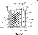
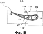
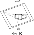
фиг.1А-1С иллюстрируют пример различных видов компонента турбины, такого как лопатка турбины или статорная лопасть, имеющего сменный соединитель, согласно одному примеру осуществления настоящего изобретения, показанный на фиг.1А на общем виде, на фиг.1В - в разрезе по линии В-В на фиг.1А, и на фиг.1С - на виде сверху на фиг.1А по стрелке А;FIGS. 1A-1C illustrate an example of various types of turbine component, such as a turbine blade or stator blade having a replaceable connector, according to one embodiment of the present invention, shown in FIG. 1A in a general view, in FIG. 1B is a sectional view taken along line B -B in figa, and in figs - in a top view in figa along arrow A;
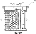
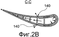
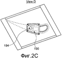
фиг.2А-2С иллюстрируют компонент турбины, такой как лопатка турбины или статорная лопасть, имеющий другой сменный соединитель, согласно одному примеру осуществления настоящего изобретения, показанный на фиг.2А на общем виде, на фиг.2В - в разрезе по линии С-С на фиг.2А, и на фиг.2С - на виде сверху на фиг.2А по стрелке D;2A-2C illustrate a turbine component, such as a turbine blade or stator vane, having another interchangeable connector, according to one embodiment of the present invention, shown in FIG. 2A in a general view, in FIG. 2B is a sectional view taken along line CC on figa, and on figs - in a top view in figa along arrow D;
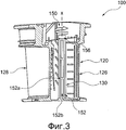
фиг.3 иллюстрирует пример осуществления компонента турбины с вставкой согласно одному примеру осуществления настоящего изобретения на общем виде;FIG. 3 illustrates an embodiment of an insert turbine component according to one embodiment of the present invention in a general view;
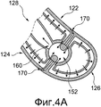
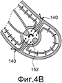
фиг.4А и 4В иллюстрируют внутреннюю бандажную полку с вставкой для показанного на фиг.3 компонента турбины согласно одному примеру осуществления настоящего изобретения на виде сверху;4A and 4B illustrate an internal retaining shelf with an insert for the turbine component shown in FIG. 3 according to one embodiment of the present invention in a plan view;
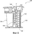
фиг.5 иллюстрируют пример осуществления компонента турбины с вставкой согласно другому примеру осуществления настоящего изобретения на общем виде;5 illustrate an embodiment of an insert turbine component according to another embodiment of the present invention in a general view;
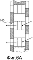
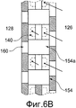
фиг.6А и 6В иллюстрируют внутреннюю бандажную полку с вставкой для показанного на фиг.5 компонента турбины согласно одному примеру осуществления настоящего изобретения на виде сверху.6A and 6B illustrate an internal retaining shelf with an insert for the turbine component shown in FIG. 5 according to one embodiment of the present invention in a plan view.
В описании чертежей для обозначения одинаковых частей используются одинаковые позиции.In the description of the drawings, the same reference numbers are used to indicate identical parts.
ОПИСАНИЕ ПРЕДПОЧТИТЕЛЬНЫХ ВАРИАНТОВ ОСУЩЕСТВЛЕНИЯ ИЗОБРЕТЕНИЯDESCRIPTION OF THE PREFERRED EMBODIMENTS OF THE INVENTION
Для более глубокого понимания настоящего изобретения ниже приводится подробное описание, включая прилагаемую формулу изобретения, со ссылками на указанные выше чертежи. В приведенном ниже описании приводится пояснение множества специальных деталей для обеспечения глубокого понимания настоящего изобретения. Однако специалистам в данной области техники следует понимать, что данное изобретение может быть реализовано без этих специальных деталей. В других случаях структуры и устройства показаны лишь схематично, для обеспечения ясности раскрытия. Ссылки в данном описании на «один вариант осуществления», «вариант осуществления», «другой вариант осуществления», «различные варианты осуществления» означают, что конкретный признак, структура или характеристика, описание которых приведено в связи с вариантом осуществления, включены по меньшей мере в один вариант осуществления настоящего изобретения. Появление фразы «в одном варианте осуществления» в различных местах описания не обязательно относится к одному и тому же варианту осуществления, а также отдельные или альтернативные варианты осуществления взаимно не исключают другие варианты осуществления. Кроме того, приведено описание различных признаков, которые могут иметься в некоторых вариантах осуществления и отсутствовать в других вариантах осуществления. Аналогичным образом приведено описание различных требований, которые могут быть требованиями для некоторых вариантов осуществления, но не требованиями для других вариантов осуществления.For a better understanding of the present invention, the following is a detailed description, including the appended claims, with reference to the above drawings. In the description below, many specific details are explained to provide a thorough understanding of the present invention. However, it will be understood by those skilled in the art that the invention may be practiced without these special details. In other cases, structures and devices are shown only schematically, to ensure clarity of disclosure. References in this description to “one embodiment”, “embodiment”, “another embodiment”, “various embodiments” mean that a particular feature, structure or characteristic described in connection with the embodiment is included at least in one embodiment of the present invention. The appearance of the phrase “in one embodiment” at various places in the description does not necessarily refer to the same embodiment, and individual or alternative embodiments do not mutually exclude other embodiments. In addition, a description is given of various features that may or may not exist in some embodiments. Similarly, a description is given of various requirements, which may be requirements for some embodiments, but not requirements for other embodiments.
Хотя последующее описание содержит многие особенности для иллюстрации, специалистам в данной области техники следует понимать, что многие вариации и/или изменения этих деталей входят в объем настоящего изобретения. Аналогичным образом, хотя описание многих признаков настоящего изобретения приведено по отдельности или в связи друг с другом, специалистам в данной области техники следует понимать, что многие из этих признаков могут быть предусмотрены независимо друг от друга. В соответствии с этим описание настоящего изобретения приводится без потери всеобщности и без создания ограничений настоящего изобретения. Кроме того, «один» или «другой» не означают ограничение количества, а означают присутствие по меньшей мере одного обозначаемого элемента.Although the following description contains many features for illustration, it will be understood by those skilled in the art that many variations and / or changes to these details are within the scope of the present invention. Similarly, although many features of the present invention are described individually or in connection with one another, those skilled in the art will appreciate that many of these features may be provided independently of one another. In accordance with this description of the present invention is provided without loss of generality and without creating limitations of the present invention. In addition, “one” or “another” does not mean quantity limitation, but mean the presence of at least one designated element.
На фиг.1-6В показаны в различных проекциях примеры осуществления компонента 100 газовой турбины для создания ступени газовой турбины, выполненного с возможностью изменения схемы охлаждения посредством охлаждающего воздуха (в режиме пленочного охлаждения и в режиме не пленочного охлаждения). На фиг.1А-1С показан в различных проекциях пример осуществления компонента 100 турбины, такой как лопатка турбины или статорная лопасть, имеющий сменный соединитель. На фиг.2А-2С показан в различных проекциях пример осуществления компонента 100 турбины, такой как лопатка турбины или статорная лопасть, имеющий другой сменный соединитель. На фиг.3-5 показаны в изометрической проекции компоненты 100 турбины с различными типами вставок (описание которых приведено ниже) в качестве вариантов осуществления настоящего изобретения, в то время как на фиг.4А, 4В, 6А и 6В показаны различные компоненты 100 турбины на виде сверху. Компонент 100 турбины может быть лопатками турбины, статорными лопастями или тепловыми экранами, выполненными за одно целое или в виде части турбины. Однако для краткости, ясности и исключения повторов описание компонента 100 турбины приводится применительно к лопаткам турбины без исключения из объема изобретения статорных лопастей или тепловых экранов или других турбинных компонентов. Кроме того, в конструкции и расположении турбины или компонентов 100 турбины (называемых в последующем лопаткой 100) для специалистов в данной области техники могут быть хорошо известны различные связанные с ними элементы, однако для целей понимания настоящего изобретения нет необходимости в указании и в пояснении всех конструктивных элементов. Достаточно отметить, что, как показано на фиг.1-6В, в лопатке 100 показаны лишь те компоненты, которые необходимы для описания различных вариантов осуществления настоящего изобретения.Figures 1-6B show, in various projections, examples of embodiments of a
Как показано на фиг.1А-2В, лопатка 100 включает профильный участок 120 пера, по меньшей мере один охлаждающий проход 130, множество отверстий 140 для образования пленки и сменные соединители 180, 190. Профильный участок 120 пера включает корыто 122 и спинку 124, соединенные вместе на хордово противоположных входной кромке 126 и выходной кромке 128. Кроме того, охлаждающий проход 130 выполнен с прохождением между корытом 122 и спинкой 124 вдоль входной кромки 126. Охлаждающий проход 130 обеспечивает возможность прохождения охлаждающей текучей среды в нем, которую он может получать из источника текучей среды, такого как компрессор двигателя или любого другого источника. Может иметься лишь один охлаждающий проход 130, или же не выходя из объема настоящего изобретения лопатка 100 может включать больше чем один охлаждающий проход в зависимости от потребности.As shown in figa-2B, the
Кроме того, лопатка 100 включает множество отверстий 140 для образования пленки, продолжающихся между охлаждающим проходом 130 и внешней стороной профильного участка 120 пера. Множество отверстий 140 для образования пленки (называемых в последующем пленочными отверстиями 140) могут иметь геометрическую конфигурацию, выбранную из цилиндрической, веерной или консольной выемки, без исключения из объема изобретения других геометрических конфигураций, известных из уровня техники. Пленочные отверстия 140 выполнены с возможностью направления по меньшей мере части охлаждающей текучей среды из охлаждающего прохода 130 для прохождения по части профильного участка 120 пера с образованием пленки охлаждающего воздуха над частью профильного участка 120 пера для ее охлаждения, что называется режимом пленочного охлаждения. Однако, как указывалось выше, в зависимости от различных уровней температуры такая воздушная пленка на части профильного участка 120 пера может не требоваться (что называется режимом без пленочного охлаждения) и в соответствии с этим может требоваться изменение схемы охлаждения для лопаток или лопастей с режима пленочного охлаждения в режим без пленочного охлаждения или наоборот.In addition, the
Для этой цели, в противоположность уровню техники, лопатка 100 включает сменные соединители 180, 190. Сменные соединители 180, 190 выполнены по отдельности для охлаждающего прохода 130. Сменные соединители 180, 190 предназначены для изменения схемы охлаждения посредством изменения потока охлаждающей текучей среды в соответствии с открыванием и закрыванием передних пленочных отверстий 140. Один сменный соединитель 180, как показано на фиг.1А-1С, включает покрывающий изгиб 182. Соединитель 180 с покрывающим изгибом 182 выполнен с возможностью крепления посредством подходящих средств, таких как уплотнительное устройство 184, над охлаждающим проходом 130. Однако не выходя из объема настоящего изобретения соединитель 180 может быть закреплен посредством других подходящих средств, таких как пайка твердым припоем, сварка или другое механическое соединение. Соединитель 180 обеспечивает возможность прохождения по меньшей мере части охлаждающей текучей среды от входной кромки 126 к выходной кромке 128 внутри внутренней части профильного участка 120 пера, когда пленочные отверстия 140 закрыты. Кроме того, другой сменный соединитель 190, как показано на фиг.2А-2С, включает плоский покрывающий элемент 192 с отверстием 194. Сменный соединитель 190 выполнен с возможностью крепления посредством подходящих средств, таких как уплотнительная система 196, над охлаждающим проходом 130. Однако не выходя из объема настоящего изобретения соединитель 190, аналогично соединителю 180, может быть закреплен посредством других подходящих средств, таких как пайка твердым припоем, сварка или другое механическое соединение. Соединитель 190 обеспечивает возможность протекания охлаждающей текучей среды из отверстия 194 внутри охлаждающего прохода 130. Кроме того, охлаждающая текучая среда из охлаждающего прохода 130 направляется к пленочным отверстиям 140 для прохождения охлаждающей текучей среды от входной кромки 126 к выходной кромке 128, когда множество пленочных отверстий 140 открыты, для образования пленочного охлаждающего слоя, проходящего от входной кромки 126 к выходной кромке 128. Сменные соединители 180, 190 выполнены с возможностью изменения схемы охлаждения посредством охлаждающей текучей среды, независимо от режимов охлаждения с пленкой или без пленки, в лопатке 100 в соответствии с требованиями в зависимости от уровней температуры в турбине.For this purpose, in contrast to the prior art, the
Как показано на фиг.3-6В в различных вариантах осуществления настоящего изобретения, лопатка 100 может включать вставку 150. Вставка 150 выполнена с возможностью функционального расположения внутри охлаждающего прохода 130 в согласовании со сменными соединителями 180, 190 по меньшей мере для частичного закрывания и открывания пленочных отверстий 140 в соединении с изменением схемы охлаждения. В частности, в режиме охлаждения без пленки (при низких уровнях температуры внутри турбины) вставка 150 выполнена с возможностью по меньшей мере частичного закрывания пленочных отверстий 140 для прерывания потока охлаждающей текучей среды над частью профильного участка 120 пера. Кроме того, в режиме охлаждения с пленкой (при высоких уровнях температуры внутри турбины) вставка 150 выполнена с возможностью открывания пленочных отверстий 140 для обеспечения протекания охлаждающей текучей среды над частью профильного участка 120 пера для образования охлаждающего слоя воздушной пленки, продолжающегося от входной кромки 126 к выходной кромке 128.As shown in FIGS. 3-6B, in various embodiments of the present invention, the
В одном варианте осуществления, как показано на фиг.3, 4А и 4В, вставка 150 может быть цилиндрическим поворотным клапаном (обозначенным позицией 152), выполненным с возможностью поворота вокруг своей оси Х для закрывания и открывания пленочных отверстий 140. В этом варианте осуществления цилиндрический поворотный клапан 152 может содержать части 152 со сквозным отверстием 152а, так что цилиндрический поворотный клапан поворачивается для согласования и рассогласования сквозных отверстий 152b частей 152a со сквозным отверстием с пленочными отверстиями 140 соответственно в режиме охлаждения с пленкой и без пленки для открывания и закрывания пленочных отверстий 140 для обеспечения и прерывания охлаждающей текучей среды.In one embodiment, as shown in FIGS. 3, 4A and 4B, the
В другом варианте осуществления, как показано на фиг.5, 6А и 6В, вставка 150 является цилиндрическим переключателем (обозначенным позицией 154), выполненным с возможностью вертикального перемещения вдоль оси Y для закрывания и открывания пленочных отверстий 140. Цилиндрический переключатель 154 может содержать расположенные на расстоянии друг от друга ребра 154а, так что цилиндрический переключатель 154 выполнен с возможностью перемещения вертикально в согласовании и рассогласованием ребер 154a с множеством пленочных отверстий 140 соответственно в режиме охлаждения с пленкой и без пленки для обеспечения и прерывания прохождения охлаждающей текучей среды.In another embodiment, as shown in FIGS. 5, 6A and 6B, the
В одном варианте осуществления вставку 150, такую как цилиндрический поворотный клапан 152 или цилиндрический переключатель 154, можно приводить в действие вручную посредством поворота вокруг оси Х или перемещения вдоль оси Y соответственно. В другом варианте осуществления вставку 150, такую как цилиндрический поворотный клапан 152 или цилиндрический переключатель 154, можно приводить в действие автоматически посредством поворота вокруг оси Х или перемещения вдоль оси Y соответственно, посредством гидравлических, пневматических или электрических устройств. Цилиндрический переключатель 154 может быть расположен внутри профильного участка 120 пера и может быть механическим переключателем или перемещаемой частью с отверстиями. В ручном режиме цилиндрический поворотный клапан 152 или цилиндрический переключатель 154 могут быть доступны после разборки двигателя и после разборки части, содержащей лопатки турбины, или после разборки двигателя, но без разборки части, содержащей статорные лопасти. В автоматическом режиме цилиндрический поворотный клапан 152 или цилиндрический переключатель 154 могут иметь активное управление, такое как элемент 156, для эффективного согласования части во время работы с использованием дистанционного исполнительного механизма, такого как гидравлические, пневматические или электромеханические переключатели, или с использованием биметаллических устройств.In one embodiment, an
В другом варианте осуществления настоящего изобретения лопатка 100 дополнительно включает множество задних сквозных отверстий 160, выполненных на стороне входной кромки 126 в согласовании с охлаждающим проходом 130. Задние сквозные отверстия 160 выполнены с возможностью направления по меньшей мере части охлаждающей текучей среды из охлаждающего прохода 130 для прохождения внутри внутренней части профильного участка 120 пера от входной кромки 126 к выходной кромке 128 для внутреннего охлаждения лопатки 100 или профильного участка 120 пера. Множество задних сквозных отверстий 160 могут быть выполнены с возможностью закрывания и открывания посредством вставки 150 указанным выше образом. Выходная кромка 128 может включать игольчатую кромку 128а (как показано на фиг.1А и 2А), через который может выходить охлаждающая текучая среда после охлаждения внутренней части профильного участка 120 пера. Различные стрелки на фиг.4А и 4В показывают направление потока охлаждающего воздуха, без какого-либо ограничения, посредством пленочных отверстий 140 и задних сквозных отверстий 160. Кроме того, различные стрелки на фиг.6А и 6В показывают направление потока охлаждающего воздуха из охлаждающего прохода 130 к профильному участку 120 пера посредством пленочных отверстий 140 (см. фиг.6В) и направление потока охлаждающего воздуха из охлаждающего прохода 130 к задним сквозным отверстиям 160 (см. фиг.6А) в качестве иллюстрации. Аналогичным образом на фиг.1А, 1В, 2А и 2В также показано направление потока охлаждающего воздуха. Таким образом, без каких-либо ограничений, лопатка 100 может также включать принудительное охлаждение 132, которое может принимать охлаждающую текучую среду из охлаждающего прохода 130 для охлаждения входной кромки 126. Лопатка 100 может также включать каналы 134, которые могут обеспечивать выход охлаждающей текучей среды от входной кромки 126 и направление охлаждающего воздуха к выходной кромке через множество задних сквозных отверстий 160 для охлаждения выходной кромки 128. Описание множества задних сквозных отверстий 160 будет приведено ниже.In another embodiment of the present invention, the
В другом варианте осуществления настоящего изобретения лопатка 100 может дополнительно включать множество временных пробок 170 (как показано лишь на фиг.4А). Временные пробки 170 могут быть выполнены с возможностью введения в пленочные отверстия 140 в режиме без пленки для защиты пленочных отверстий 140 от впрыска горячих газов или оксидантов. В одном варианте осуществления временные пробки 170 могут быть керамическими пробками, металлическими пробками, высокотемпературным клеем или керамическими пробками, пробками, покрытыми теплопроводным соединением. В режиме охлаждения с пленкой временные пробки 170 можно удалять для открывания пленочных отверстий 140 посредством механического сжимания или химического разложения, на месте или дистанционно.In another embodiment of the present invention, the
Компоненты 100 газовой турбины, такие как лопатки турбины или статорные лопасти или любая другая часть, такая как тепловые экраны, согласно данному изобретению являются предпочтительными во многих отношениях. Компоненты 100 газовой турбины оптимизированы для изменения схемы охлаждения эффективным образом, так что требуемую схему охлаждения легко получать экономичным и согласованным образом. Сменные соединители и вставки обеспечивают возможность изменения схемы охлаждения и восстановления схемы охлаждения экономичным образом, не требуя дорогостоящих литейных форм. Различные другие преимущества и признаки настоящего изобретения следуют из приведенного выше описания и прилагаемой формулы изобретения.
Приведенное выше описание специальных вариантов осуществления настоящего изобретения дано для целей иллюстрации и описания. Их не следует рассматривать в качестве исчерпывающих или ограничивающих данное изобретение точно раскрытыми формами, и понятно, что возможны многие модификации и вариации в свете приведенных выше идей. Варианты осуществления выбраны и описаны для наилучшего пояснения принципов настоящего изобретения и их практического применения, для предоставления специалистам в данной области техники возможности наилучшим образом использовать данное изобретение и различные варианты осуществления с различными модификациями, как это требуется при конкретном применении. Понятно, что различные упущения и эквивалентные замены возможны или могут быть целесообразными без отхода от идеи и выхода за объем настоящего изобретения, определяемый формулой изобретения.The above description of specific embodiments of the present invention is given for purposes of illustration and description. They should not be construed as exhaustive or limiting the invention to precisely disclosed forms, and it is understood that many modifications and variations are possible in light of the above teachings. Embodiments have been selected and described to best explain the principles of the present invention and their practical application, in order to enable those skilled in the art to make best use of the present invention and various embodiments with various modifications as required for a particular application. It is clear that various omissions and equivalent replacements are possible or may be appropriate without departing from the idea and going beyond the scope of the present invention defined by the claims.
СПИСОК ССЫЛОЧНЫХ ПОЗИЦИЙLIST OF REFERENCE POSITIONS
100 - Компонент газовой турбины100 - Component of a gas turbine
120 - Профильный участок пера120 - Profile section of the pen
122 - Корыто122 - Trough
124 - Спинка124 - Back
126 - Входная кромка126 - Entrance edge
128 - Выходная кромка128 - output edge
128а - Игольчатая кромка128a - Needle Edge
130 - Охлаждающий проход130 - Cooling passage
132 - Принудительное охлаждение132 - Forced cooling
134 - Каналы134 - Channels
140 - Множество пленочных отверстий140 - Many film holes
150 - Вставка150 - Insert
152 - Цилиндрический поворотный клапан (один вариант вставки 150)152 - Cylindrical rotary valve (one insert option 150)
152а - Части со сквозными отверстиями152a - Parts with Through Holes
152b - Сквозные отверстия152b - Through Holes
154 - Цилиндрический переключатель (другой вариант вставки 150)154 - Cylindrical switch (another insertion option 150)
154 - Ребра154 - Ribs
156 - Элемент156 - Element
160 - Множество задних охлаждающих отверстий160 - Many rear cooling holes
170 - Множество временных пробок170 - Many temporary traffic jams
180,190 - Сменные соединители180,190 - Replaceable Connectors
182 - Покрывающий изгиб182 - Covering bend
184 - Уплотнительное устройство184 - Sealing device
192 - Плоский покрывающий элемент192 - Flat covering element
194 - Отверстие194 - Hole
196 - Уплотнительное устройство196 - Sealing device
Claims (17)
профильный участок (120) пера, имеющий корыто (122) и спинку (124), соединенные вместе на хордово противоположных входной кромке (126) и выходной кромке (128);
по меньшей мере один охлаждающий проход (130), продолжающийся между корытом (122) и спинкой (124) вдоль входной кромки (126), при этом по меньшей мере один охлаждающий проход (130) обеспечивает возможность протекания через него охлаждающей текучей среды;
множество пленочных отверстий (140), продолжающихся между по меньшей мере одним охлаждающим проходом (130) и внешней стороной профильного участка (120) пера, при этом множество пленочных отверстий (140) выполнены с возможностью направления по меньшей мере части потока охлаждающей текучей среды из по меньшей мере одного охлаждающего прохода (130) по части профильного участка (120) пера; и
сменные соединители (180, 190), выполненные с возможностью изменения для по меньшей мере одного охлаждающего прохода (130) поочередно схемы охлаждения посредством изменения протекания охлаждающей текучей среды в согласовании с открыванием и закрыванием множества пленочных отверстий (140).1. A gas turbine component (100) for forming a part of a gas turbine stage, configured to change its cooling circuit, comprising:
a profile section (120) of the pen having a trough (122) and a back (124) connected together at the chordally opposite input edge (126) and output edge (128);
at least one cooling passage (130) extending between the trough (122) and the backrest (124) along the inlet edge (126), with at least one cooling passage (130) allowing the cooling fluid to flow through it;
a plurality of film openings (140) extending between at least one cooling passage (130) and the outside of the profile portion (120) of the pen, wherein the plurality of film openings (140) are configured to direct at least a portion of the flow of cooling fluid from at least one cooling passage (130) in part of the profile section (120) of the pen; and
interchangeable connectors (180, 190) configured to change for at least one cooling passage (130) alternately the cooling circuit by changing the flow of the cooling fluid in accordance with the opening and closing of a plurality of film holes (140).
вставку (150), функционально расположенную внутри по меньшей мере одного охлаждающего прохода (130) в согласовании со сменными соединителями (180, 190) для по меньшей мере частичного закрывания и открывания множества пленочных отверстий (140) в соответствии с изменением схемы охлаждения.4. The gas turbine component (100) according to claim 1, further comprising:
an insert (150) functionally located inside at least one cooling passage (130) in accordance with interchangeable connectors (180, 190) for at least partially closing and opening a plurality of film holes (140) in accordance with a change in the cooling circuit.
Priority Applications (6)
| Application Number | Priority Date | Filing Date | Title |
|---|---|---|---|
| RU2014103219/06A RU2568763C2 (en) | 2014-01-30 | 2014-01-30 | Gas turbine component |
| US15/114,005 US10883372B2 (en) | 2014-01-30 | 2015-01-26 | Gas turbine component |
| EP15700899.6A EP3099902B1 (en) | 2014-01-30 | 2015-01-26 | Gas turbine component |
| JP2016549321A JP2017504759A (en) | 2014-01-30 | 2015-01-26 | Gas turbine components |
| PCT/EP2015/051448 WO2015113925A1 (en) | 2014-01-30 | 2015-01-26 | Gas turbine component |
| CN201580006655.2A CN105980662B (en) | 2014-01-30 | 2015-01-26 | Gas turbine components |
Applications Claiming Priority (1)
| Application Number | Priority Date | Filing Date | Title |
|---|---|---|---|
| RU2014103219/06A RU2568763C2 (en) | 2014-01-30 | 2014-01-30 | Gas turbine component |
Publications (2)
| Publication Number | Publication Date |
|---|---|
| RU2014103219A RU2014103219A (en) | 2015-08-10 |
| RU2568763C2 true RU2568763C2 (en) | 2015-11-20 |
Family
ID=52394272
Family Applications (1)
| Application Number | Title | Priority Date | Filing Date |
|---|---|---|---|
| RU2014103219/06A RU2568763C2 (en) | 2014-01-30 | 2014-01-30 | Gas turbine component |
Country Status (6)
| Country | Link |
|---|---|
| US (1) | US10883372B2 (en) |
| EP (1) | EP3099902B1 (en) |
| JP (1) | JP2017504759A (en) |
| CN (1) | CN105980662B (en) |
| RU (1) | RU2568763C2 (en) |
| WO (1) | WO2015113925A1 (en) |
Cited By (1)
| Publication number | Priority date | Publication date | Assignee | Title |
|---|---|---|---|---|
| RU2716648C1 (en) * | 2019-07-16 | 2020-03-13 | ФЕДЕРАЛЬНОЕ ГОСУДАРСТВЕННОЕ БЮДЖЕТНОЕ ОБРАЗОВАТЕЛЬНОЕ УЧРЕЖДЕНИЕ ВЫСШЕГО ОБРАЗОВАНИЯ "Брянский государственный технический университет" | Cooled blade of gas turbine |
Families Citing this family (1)
| Publication number | Priority date | Publication date | Assignee | Title |
|---|---|---|---|---|
| US9670797B2 (en) * | 2012-09-28 | 2017-06-06 | United Technologies Corporation | Modulated turbine vane cooling |
Citations (6)
| Publication number | Priority date | Publication date | Assignee | Title |
|---|---|---|---|---|
| US4162136A (en) * | 1974-04-05 | 1979-07-24 | Rolls-Royce Limited | Cooled blade for a gas turbine engine |
| US4650399A (en) * | 1982-06-14 | 1987-03-17 | United Technologies Corporation | Rotor blade for a rotary machine |
| US4992026A (en) * | 1986-03-31 | 1991-02-12 | Kabushiki Kaisha Toshiba | Gas turbine blade |
| US5387086A (en) * | 1993-07-19 | 1995-02-07 | General Electric Company | Gas turbine blade with improved cooling |
| RU2146766C1 (en) * | 1997-06-26 | 2000-03-20 | Сосьете Насьональ Д'Этюд э де Констрюксьон де Мотер Д'Авиасьон "СНЕКМА" | System of blades cooled by means of spiral guide surface, cascade collision and system with bridges in double shell |
| RU2208683C1 (en) * | 2002-01-08 | 2003-07-20 | Ульяновский государственный технический университет | Cooled blade of turbine |
Family Cites Families (14)
| Publication number | Priority date | Publication date | Assignee | Title |
|---|---|---|---|---|
| US3045965A (en) * | 1959-04-27 | 1962-07-24 | Rolls Royce | Turbine blades, vanes and the like |
| US3005496A (en) * | 1959-08-24 | 1961-10-24 | Hiller Aircraft Corp | Airfoil boundary layer control means |
| BE794195A (en) * | 1972-01-18 | 1973-07-18 | Bbc Sulzer Turbomaschinen | COOLED STEERING VANE FOR GAS TURBINES |
| US3937588A (en) * | 1974-07-24 | 1976-02-10 | United Technologies Corporation | Emergency control system for gas turbine engine variable compressor vanes |
| US5726348A (en) | 1996-06-25 | 1998-03-10 | United Technologies Corporation | Process for precisely closing off cooling holes of an airfoil |
| EP0925426A1 (en) * | 1996-09-04 | 1999-06-30 | Siemens Aktiengesellschaft | Turbine blade which can be exposed to a hot gas flow |
| JP4087586B2 (en) * | 2001-09-13 | 2008-05-21 | 株式会社日立製作所 | Gas turbine and its stationary blade |
| DE10339857A1 (en) * | 2003-08-29 | 2005-03-24 | Daimlerchrysler Ag | Combustion engine with motor brake system esp in the form of a constant throttle having a bypass unit in the form of a combined switch and throttle valve |
| EP1591626A1 (en) * | 2004-04-30 | 2005-11-02 | Alstom Technology Ltd | Blade for gas turbine |
| US7708229B1 (en) * | 2006-03-22 | 2010-05-04 | West Virginia University | Circulation controlled airfoil |
| EP2407639A1 (en) * | 2010-07-15 | 2012-01-18 | Siemens Aktiengesellschaft | Platform part for supporting a nozzle guide vane for a gas turbine |
| US20130104517A1 (en) | 2011-10-31 | 2013-05-02 | Victor Hugo Silva Correia | Component and method of fabricating the same |
| US9670797B2 (en) * | 2012-09-28 | 2017-06-06 | United Technologies Corporation | Modulated turbine vane cooling |
| US9664111B2 (en) * | 2012-12-19 | 2017-05-30 | United Technologies Corporation | Closure of cooling holes with a filing agent |
-
2014
- 2014-01-30 RU RU2014103219/06A patent/RU2568763C2/en active
-
2015
- 2015-01-26 US US15/114,005 patent/US10883372B2/en active Active
- 2015-01-26 JP JP2016549321A patent/JP2017504759A/en active Pending
- 2015-01-26 WO PCT/EP2015/051448 patent/WO2015113925A1/en active Application Filing
- 2015-01-26 EP EP15700899.6A patent/EP3099902B1/en active Active
- 2015-01-26 CN CN201580006655.2A patent/CN105980662B/en active Active
Patent Citations (6)
| Publication number | Priority date | Publication date | Assignee | Title |
|---|---|---|---|---|
| US4162136A (en) * | 1974-04-05 | 1979-07-24 | Rolls-Royce Limited | Cooled blade for a gas turbine engine |
| US4650399A (en) * | 1982-06-14 | 1987-03-17 | United Technologies Corporation | Rotor blade for a rotary machine |
| US4992026A (en) * | 1986-03-31 | 1991-02-12 | Kabushiki Kaisha Toshiba | Gas turbine blade |
| US5387086A (en) * | 1993-07-19 | 1995-02-07 | General Electric Company | Gas turbine blade with improved cooling |
| RU2146766C1 (en) * | 1997-06-26 | 2000-03-20 | Сосьете Насьональ Д'Этюд э де Констрюксьон де Мотер Д'Авиасьон "СНЕКМА" | System of blades cooled by means of spiral guide surface, cascade collision and system with bridges in double shell |
| RU2208683C1 (en) * | 2002-01-08 | 2003-07-20 | Ульяновский государственный технический университет | Cooled blade of turbine |
Cited By (1)
| Publication number | Priority date | Publication date | Assignee | Title |
|---|---|---|---|---|
| RU2716648C1 (en) * | 2019-07-16 | 2020-03-13 | ФЕДЕРАЛЬНОЕ ГОСУДАРСТВЕННОЕ БЮДЖЕТНОЕ ОБРАЗОВАТЕЛЬНОЕ УЧРЕЖДЕНИЕ ВЫСШЕГО ОБРАЗОВАНИЯ "Брянский государственный технический университет" | Cooled blade of gas turbine |
Also Published As
| Publication number | Publication date |
|---|---|
| EP3099902A1 (en) | 2016-12-07 |
| US10883372B2 (en) | 2021-01-05 |
| WO2015113925A1 (en) | 2015-08-06 |
| JP2017504759A (en) | 2017-02-09 |
| US20160341047A1 (en) | 2016-11-24 |
| EP3099902B1 (en) | 2019-06-19 |
| CN105980662B (en) | 2018-06-22 |
| CN105980662A (en) | 2016-09-28 |
| RU2014103219A (en) | 2015-08-10 |
Similar Documents
| Publication | Publication Date | Title |
|---|---|---|
| CN103492677B (en) | Airfoil in gas turbine engine | |
| JP6669436B2 (en) | Platform cooling mechanism and method for forming a platform cooling mechanism on a turbine rotor blade | |
| JP5947519B2 (en) | Apparatus and method for cooling the platform area of a turbine rotor blade | |
| RU2640144C2 (en) | Seal assembly for gas turbine engine including grooves in inner band | |
| US9617859B2 (en) | Turbine components with passive cooling pathways | |
| US9803559B2 (en) | Variable vane and seal arrangement | |
| RU2543100C2 (en) | Working blade for gas turbine, manufacturing method for such blade and gas turbine with such blade | |
| JP7051289B2 (en) | Turbine airfoil with trailing edge cooling circuit | |
| CN102619574B (en) | For cooling down the Apparatus and method in turbine rotor blade platform district | |
| JP6010295B2 (en) | Apparatus and method for cooling the platform area of a turbine rotor blade | |
| RU2568763C2 (en) | Gas turbine component | |
| US9745853B2 (en) | Integrated circuit cooled turbine blade | |
| JP2017096270A (en) | Gas turbine engine with vane having cooling inlet | |
| RU2699115C2 (en) | Method of adjusting sealing gap in turbomachine and corresponding turbomachine | |
| EP2852734B1 (en) | Passive thermostatic valve | |
| US11377957B2 (en) | Gas turbine engine with a diffuser cavity cooled compressor | |
| CN108699913B (en) | Cooling system for a turbine engine | |
| JP2015113835A (en) | Steam turbine and methods of assembling the same | |
| CN104975885B (en) | Thrust plate sub-assembly | |
| CN106050317A (en) | Turbine airfoil | |
| KR20160056821A (en) | Cooling for turbine blade platform-aerofoil joints | |
| WO2017003455A1 (en) | Turbine stator vane cooling circuit with flow stream separation | |
| US10190427B2 (en) | Turbine nozzle box | |
| RU2799867C2 (en) | Gas turbine engine cooling device | |
| US11486313B2 (en) | Linear electric air valve |
Legal Events
| Date | Code | Title | Description |
|---|---|---|---|
| HC9A | Changing information about inventors | ||
| PD4A | Correction of name of patent owner | ||
| PC41 | Official registration of the transfer of exclusive right |
Effective date: 20170426 |