RU2563780C2 - Nut and combination of bolt element and nut - Google Patents
Nut and combination of bolt element and nut Download PDFInfo
- Publication number
- RU2563780C2 RU2563780C2 RU2013107024/12A RU2013107024A RU2563780C2 RU 2563780 C2 RU2563780 C2 RU 2563780C2 RU 2013107024/12 A RU2013107024/12 A RU 2013107024/12A RU 2013107024 A RU2013107024 A RU 2013107024A RU 2563780 C2 RU2563780 C2 RU 2563780C2
- Authority
- RU
- Russia
- Prior art keywords
- nut
- bolt
- rotation
- hole
- profiling
- Prior art date
Links
- 230000000903 blocking effect Effects 0.000 claims description 12
- 230000004323 axial length Effects 0.000 claims description 6
- 238000003780 insertion Methods 0.000 claims description 5
- 230000037431 insertion Effects 0.000 claims description 5
- 230000000694 effects Effects 0.000 abstract description 2
- 239000000126 substance Substances 0.000 abstract 1
- 230000006835 compression Effects 0.000 description 3
- 238000007906 compression Methods 0.000 description 3
- 238000009434 installation Methods 0.000 description 3
- 239000002184 metal Substances 0.000 description 3
- 239000000463 material Substances 0.000 description 2
- 238000000926 separation method Methods 0.000 description 2
- 230000000295 complement effect Effects 0.000 description 1
- 238000006073 displacement reaction Methods 0.000 description 1
- 238000007373 indentation Methods 0.000 description 1
- 230000003993 interaction Effects 0.000 description 1
- 230000002028 premature Effects 0.000 description 1
- 239000013589 supplement Substances 0.000 description 1
Images


Classifications
-
- F—MECHANICAL ENGINEERING; LIGHTING; HEATING; WEAPONS; BLASTING
- F16—ENGINEERING ELEMENTS AND UNITS; GENERAL MEASURES FOR PRODUCING AND MAINTAINING EFFECTIVE FUNCTIONING OF MACHINES OR INSTALLATIONS; THERMAL INSULATION IN GENERAL
- F16B—DEVICES FOR FASTENING OR SECURING CONSTRUCTIONAL ELEMENTS OR MACHINE PARTS TOGETHER, e.g. NAILS, BOLTS, CIRCLIPS, CLAMPS, CLIPS OR WEDGES; JOINTS OR JOINTING
- F16B39/00—Locking of screws, bolts or nuts
- F16B39/22—Locking of screws, bolts or nuts in which the locking takes place during screwing down or tightening
- F16B39/28—Locking of screws, bolts or nuts in which the locking takes place during screwing down or tightening by special members on, or shape of, the nut or bolt
-
- B—PERFORMING OPERATIONS; TRANSPORTING
- B21—MECHANICAL METAL-WORKING WITHOUT ESSENTIALLY REMOVING MATERIAL; PUNCHING METAL
- B21D—WORKING OR PROCESSING OF SHEET METAL OR METAL TUBES, RODS OR PROFILES WITHOUT ESSENTIALLY REMOVING MATERIAL; PUNCHING METAL
- B21D28/00—Shaping by press-cutting; Perforating
- B21D28/24—Perforating, i.e. punching holes
- B21D28/34—Perforating tools; Die holders
- B21D28/343—Draw punches
-
- F—MECHANICAL ENGINEERING; LIGHTING; HEATING; WEAPONS; BLASTING
- F16—ENGINEERING ELEMENTS AND UNITS; GENERAL MEASURES FOR PRODUCING AND MAINTAINING EFFECTIVE FUNCTIONING OF MACHINES OR INSTALLATIONS; THERMAL INSULATION IN GENERAL
- F16B—DEVICES FOR FASTENING OR SECURING CONSTRUCTIONAL ELEMENTS OR MACHINE PARTS TOGETHER, e.g. NAILS, BOLTS, CIRCLIPS, CLAMPS, CLIPS OR WEDGES; JOINTS OR JOINTING
- F16B37/00—Nuts or like thread-engaging members
- F16B37/08—Quickly-detachable or mountable nuts, e.g. consisting of two or more parts; Nuts movable along the bolt after tilting the nut
- F16B37/0807—Nuts engaged from the end of the bolt, e.g. axially slidable nuts
- F16B37/085—Nuts engaged from the end of the bolt, e.g. axially slidable nuts with at least one unthreaded portion in both the nut and the bolt
-
- F—MECHANICAL ENGINEERING; LIGHTING; HEATING; WEAPONS; BLASTING
- F16—ENGINEERING ELEMENTS AND UNITS; GENERAL MEASURES FOR PRODUCING AND MAINTAINING EFFECTIVE FUNCTIONING OF MACHINES OR INSTALLATIONS; THERMAL INSULATION IN GENERAL
- F16B—DEVICES FOR FASTENING OR SECURING CONSTRUCTIONAL ELEMENTS OR MACHINE PARTS TOGETHER, e.g. NAILS, BOLTS, CIRCLIPS, CLAMPS, CLIPS OR WEDGES; JOINTS OR JOINTING
- F16B39/00—Locking of screws, bolts or nuts
Abstract
Description
Изобретение относится к гайке с признаками ограничительной части пункта 1 формулы изобретения и к комбинации болта с гайкой с признаками ограничительной части пункта 8 формулы изобретения.The invention relates to a nut with the signs of the restrictive part of
Такая гайка известна, например, из US 2009/0226281 А1. В известной гайке в первой части размещены проходящие по части окружности участки резьбы, причем эти участки резьбы подвижны относительно первой части, преимущественно вертикально подвижны. Вторая часть образует контрупор для пружины сжатия, воздействующей на участки резьбы. Известную гайку можно надвигать на резьбовой болт, при этом отклоняющиеся назад участки резьбы обеспечивают возможность прохождения над резьбой. Когда затем гайку вращают, то участки резьбы входят в зацепление с резьбой болта, и гайку можно затягивать. Дополнительно предусмотренная, соединенная с возможностью поворота с первой частью подкладная шайба, которая помимо этого соединена с геометрическим замыканием с закрепленной на гайке пружинной камерой, создает вследствие напряжения пружины при затягивании гайки и прилегания подкладной шайбы к зажимаемому предмету постоянное напряжение гайки в направлении запирания, так что создается противодействие отвинчиванию.Such a nut is known, for example, from US 2009/0226281 A1. In a known nut in the first part, thread sections extending along a part of the circumference are arranged, and these thread sections are movable relative to the first part, mainly vertically movable. The second part forms a counterpart for the compression spring acting on the threads. A known nut can be threaded onto a threaded bolt, while backward tilting portions of the thread allow passage above the thread. When the nut is then rotated, the thread portions engage with the thread of the bolt, and the nut can be tightened. In addition, a washer, which is rotatably connected to the first part, is further provided, which, in addition, is geometrically closed with a spring chamber fixed to the nut, creates a constant voltage of the nut in the locking direction due to the spring tension when the nut is tightened and the washer adheres to the clamped object, so that creates an opposition to unscrewing.
Системы фиксации гайки известны также в других вариантах выполнения. Можно сослаться, например, на DE 197 01 371 В4, ЕР 2 128 461 А1, DE 198 25 132 А1 и FR 2 762 367 А1.Nut fixing systems are also known in other embodiments. You can refer, for example, to DE 197 01 371 B4, EP 2 128 461 A1, DE 198 25 132 A1 and
Кроме того, такие гайки и комбинации из гаек с болтовыми элементами известны из US 4 781 507 В1 и GB 692041 А. В предмете указанной US-публикации предусмотрены две снабженные витками резьбы части гайки, свободно поворачиваемые относительно друг друга. Кроме того, предусмотрена не имеющая профилирования вводная часть с возможностью вращения относительно указанных резьбовых частей. Возможность вращения выполненной без профилирования части относительно резьбовой части не ограничена. Обеспечивается возможность фиксации положения лишь между имеющими резьбовые выточки частями.In addition, such nuts and combinations of nuts with bolt elements are known from US 4,781,507 B1 and GB 692041 A. In the subject of this US publication, there are two screwed-in parts of the nut that are freely rotatable relative to each other. In addition, there is provided a non-profiling introductory part with the possibility of rotation relative to these threaded parts. The possibility of rotation of the part without profiling relative to the threaded part is not limited. It is possible to fix the position only between parts with threaded grooves.
Подлежащий введению в гайку болт снабжен резьбовой выточкой, за исключением своего свободного конца.The bolt to be inserted into the nut is provided with a threaded groove, with the exception of its free end.
Из указанной GB-692041 А известна гайка, в которую вкладывается деталь, которая предназначена для фиксации на внутренней стороне этой гайки с ограничением поворота и имеет отверстие, которое выполнено без какого-то особого профиля и через которое можно пропускать болт. Кроме того, в гайку можно ввинчивать резьбовую деталь, которая, в свою очередь, имеет наружную резьбу. Для разъединения эти элементы можно вывинчивать лишь совместно.From this GB-692041 A a nut is known in which a part is inserted, which is intended to be fixed on the inside of this nut with rotation restrictions and has an opening that is made without any special profile and through which a bolt can be passed. In addition, a threaded part can be screwed into the nut, which in turn has an external thread. For separation, these elements can only be unscrewed together.
Исходя из указанного уровня техники, в основу изобретения положена задача создания гайки, которая обеспечивает возможность быстрой установки на резьбовом болте и при простой конструкции обеспечивает повышенную защиту от снятия с резьбового болта. Одновременно должна быть создана комбинация из болтового элемента и гайки, которые обеспечивают возможность надежного соединения друг с другом.Based on the aforementioned prior art, the invention is based on the task of creating a nut that allows quick installation on a threaded bolt and, with a simple design, provides increased protection against removal from the threaded bolt. At the same time, a combination of a bolt element and a nut must be created, which ensures the possibility of reliable connection with each other.
Указанная задача решена сначала в предмете пункта 1 формулы изобретения тем, что вторая часть выполнена с возможностью поворота относительно первой части вокруг оси вращения с ограничением по углу, эти части в повернутом положении зафиксированы относительно друг друга с геометрическим замыканием, и для выведения из этого повернутого положения необходимо воздействовать на фиксирующую это повернутое положение деталь. Относительно указанной комбинации задача решена с помощью предмета пункта 8 формулы изобретения тем, что болт имеет сначала в направлении установки гайки вводный участок, который не имеет особых профилирований, при этом осевая длина этого вводного участка согласована с осевой длиной второй части.This problem was solved first in the subject of
Из-за не круглого контура отверстия второй части, болт может иметь, во всяком случае, на своем свободном вводном конце, согласованный с ним контур. В этом случае входящие друг в друга, при необходимости с зазором, контуры указанного болта и второй части приводят при повороте гайки указанным образом к тому, что вторая часть не поворачивается вместе с ней. Это можно использовать для различных целей. В простейшем случае, например, в качестве индикатора, например, дополнительно оформленного цветом или геометрически, который показывает пользователю, что выполнен требуемый для предотвращения снятия поворот гайки. Относительный поворот первой и второй части относительно друг друга можно распознавать также без особого оформления. Предпочтительно, такое профилирование жестко соединено с первой частью, соответственно, особенно предпочтительно выполнено с ней в виде единого целого.Due to the non-circular contour of the hole of the second part, the bolt may have, in any case, at its free input end, a contour coordinated with it. In this case, the contours of the specified bolt and the second part that enter into each other, if necessary with a gap, lead to the fact that the second part does not rotate with it when the nut is turned in this way. This can be used for various purposes. In the simplest case, for example, as an indicator, for example, additionally decorated in color or geometrically, which shows the user that the nut rotation required to prevent removal has been completed. The relative rotation of the first and second parts relative to each other can also be recognized without any special design. Preferably, such a profiling is rigidly connected to the first part, respectively, particularly preferably made with it in one piece.
Таким образом, создана просто устанавливаемая на болте стопорная гайка. За счет поворота гайки обеспечивается защита от снятия, при этом одновременно не круглый контур отверстия второй части можно использовать для того, чтобы вторая часть не поворачивалась вместе с первой, и это можно с пользой применять.Thus, a lock nut that is simply mounted on a bolt is created. Due to the rotation of the nut, protection against removal is provided, while at the same time, the non-circular contour of the hole of the second part can be used so that the second part does not rotate together with the first, and this can be used with advantage.
Относительно комбинации, гайку можно просто надвигать на болтовой элемент, а затем поворачивать так, что профилирования гайки и болтового элемента входят в зацепление друг с другом, причем при этом повороте вторая часть не поворачивается вместе с первой частью, так что в самом общем виде, как уже указывалось выше, вторую часть можно использовать в качестве индикатора того, что гайка зафиксирована на болтовом элементе, а именно, что профилирования находятся в зацеплении друг с другом, и невозможно снятие гайки с болта без дальнейшего поворота или поворота назад.Regarding the combination, the nut can simply be pushed onto the bolt element, and then rotated so that the profiling of the nut and bolt element engage with each other, and in this rotation the second part does not rotate with the first part, so that in the most general form, as already mentioned above, the second part can be used as an indicator that the nut is fixed on the bolt element, namely, that the profiles are engaged with each other, and it is impossible to remove the nut from the bolt without further turning one or turning back.
Относительно недостаточной возможности поворота болтового элемента в отверстии второй части, возможен поворот на несколько угловых градусов, например, от 0,1 до 20°. Существенным является то, что вследствие недостаточной возможности поворота происходит увлечение второй части болтом при повороте болта в гайке.Relatively insufficient possibility of rotation of the bolt element in the hole of the second part, it is possible to rotate by several angular degrees, for example, from 0.1 to 20 °. It is significant that due to the insufficient possibility of rotation, the second part is entrained by the bolt when the bolt is turned in the nut.
Ниже приводится сначала описание гайки, а затем подробное описание указанной комбинации гайки с болтовым элементом. Описание гайки, как и приведенное выше описание, имеет в обоих случаях значение, поскольку все указанные варианты выполнения гайки, как в указанной комбинации, так и отдельно, могут быть реализованы по отдельности. В соответствии с этим, описание болтового элемента также имеет значение, во всяком случае, для пояснения гайки также и независимо от указанной комбинации. При этом существенные в данном случае варианты выполнения гайки относительно, в частности, профилирования и согласования первой и второй частей и их выполнения, могут быть также реализованы в пластинчатой детали, которая может быть выполнена с возможностью поворота, а также неподвижной. В последнем случае, как правило, поворачивается лишь болт относительно этой пластинчатой детали.The following is a description of the nut first, followed by a detailed description of the indicated combination of nut and bolt element. The description of the nut, as well as the above description, is important in both cases, since all of the indicated nut embodiments, both in the indicated combination and separately, can be implemented separately. Accordingly, the description of the bolt element also matters, in any case, for the explanation of the nut, also independently of the indicated combination. In this case, nut options that are significant in this case, regarding, in particular, profiling and matching of the first and second parts and their implementation, can also be implemented in a plate part, which can be rotatable as well as stationary. In the latter case, as a rule, only a bolt is rotated relative to this plate part.
За счет того, что вторая часть выполнена с возможностью поворота относительно первой части с ограничением угла поворота, учитывается то, что на болтовом элементе профилирование в окружном направлении выполнено также лишь частично. Таким образом, ограничение по углу может быть согласовано так, что обеспечивается максимально полное перекрытие профилирований в повернутом состоянии первой части.Due to the fact that the second part is made with the possibility of rotation relative to the first part with a limited rotation angle, it is taken into account that on the bolt element, profiling in the circumferential direction is also performed only partially. Thus, the angle restriction can be coordinated so that the maximum complete overlap of profiling in the rotated state of the first part is ensured.
В положении разъединения общий контур отверстия, т.е. получающийся при таком расположении друг над другом первой и второй частей общий контур отверстия оказывается соответствующим окружному контуру болта или по меньшей мере частично больше окружного контура болта в его снабженной профилированием зоне. В качестве альтернативного решения он может быть также меньше за счет контура отверстия второй части. Это может быть, например, при таком выполнении, когда болт на своем свободном конце, со стороны которого устанавливается гайка, имеет сначала меньший контур, на который можно без проблем надвигать отверстие первой части, но который затем входит в меньший контур отверстия второй части, при этом, однако, вторая часть не может быть надвинута дальше за этот меньший контур болта.In the disconnected position, the overall contour of the hole, i.e. the overall contour of the hole obtained with this arrangement of the first and second parts one above the other turns out to correspond to the circumferential contour of the bolt or at least partially more than the circumferential contour of the bolt in its profiled area. As an alternative solution, it can also be smaller due to the contour of the hole of the second part. This can be, for example, in such an embodiment, when the bolt at its free end, from the side of which the nut is mounted, first has a smaller contour, onto which the hole of the first part can be pushed without problems, but which then enters into the smaller contour of the hole of the second part, this, however, the second part cannot be pulled further beyond this smaller contour of the bolt.
В другом варианте выполнения предусмотрено, что части в повернутом положении зафиксированы относительно друг друга с геометрическим замыканием. Особенно предпочтительно происходит блокирование. При этом повернутое положение не может быть устранено лишь за счет поворота частей относительно друг друга, даже с большим усилием, а необходимо воздействовать, например, на обеспечивающую фиксацию деталь, например, кнопку, например, посредством подъема или нажатия, или же поворота обеспечивающей фиксацию детали. Может быть также предусмотрено, что можно выполнять лишь одноразовую фиксацию. В этом случае без особых мер, например, сложного демонтажа, уже больше нельзя снять положение блокирования.In another embodiment, it is provided that the parts in the rotated position are fixed relative to each other with a geometric closure. Particularly preferably, blocking occurs. In this case, the rotated position cannot be eliminated only due to the rotation of the parts relative to each other, even with great effort, but it is necessary to act, for example, on the fixing part, for example, a button, for example, by lifting or pressing, or turning to fix the part . It may also be provided that only a one-time fixation can be performed. In this case, without special measures, for example, complex dismantling, it is no longer possible to remove the blocking position.
Кроме того, предпочтительно, что части предварительно напряжены в своем не повернутом положении, положении разъединения. Это обеспечивает возможность свободного надвигания гайки на болт, без необходимости учета подходящего для этого повернутого положения частей относительно друг друга. Когда в ходе снятия гайки с болта снимается повернутое положение, то части самостоятельно занимают не повернутое положение, т.е. положение разъединения.In addition, it is preferable that the parts are prestressed in their non-rotated, disconnected position. This makes it possible to freely slide the nut onto the bolt, without the need to take into account the suitable rotated position of the parts relative to each other. When the rotated position is removed during the removal of the nut from the bolt, the parts themselves occupy the non-rotated position, i.e. disconnect position.
Кроме того, предпочтительно контур отверстия второй части в вертикальной проекции по меньшей мере частично проходит радиально внутри относительно профилирования первой части. Некруглое выполнение предусмотрено, в частности, в зоне перекрытия с профилированием первой части относительно положения разъединения. В перекрытии с не профилированным окружным участком, в положении разъединения контур отверстия второй части предпочтительно ориентирован на круглую форму. При этом круглая форма может быть образована на основе наибольшего размера контура второго отверстия относительно проходящей через контур отверстия средней оси или относительно оси поворота, которая при насаживании гайки на болт проходит через болт. Этот наибольший размер отверстия может быть, соответственно, диаметром круглой формы. В качестве альтернативного решения или дополнительно может быть предусмотрено, что контур отверстия второй части в своей максимальной протяженности имеет размер, который в вертикальной проекции превышает размер диаметра гайки, который относительно профилирования первой части достигает вершины этого профиля, а в своей наименьшей протяженности имеет размер, который меньше указанного размера диаметра.In addition, preferably the contour of the hole of the second part in the vertical projection at least partially extends radially inside relative to the profiling of the first part. Non-circular execution is provided, in particular, in the overlapping zone with profiling of the first part relative to the separation position. In overlapping with the non-profiled circumferential portion, in the disconnected position, the contour of the opening of the second part is preferably oriented to a circular shape. The round shape can be formed on the basis of the largest size of the contour of the second hole relative to the middle axis passing through the hole contour or relative to the axis of rotation, which, when the nut is mounted on the bolt, passes through the bolt. This largest hole size may be, accordingly, a circular diameter. As an alternative solution or additionally, it can be provided that the contour of the hole of the second part in its maximum length has a size that in vertical projection exceeds the size of the diameter of the nut, which relative to the profiling of the first part reaches the top of this profile, and in its smallest length has a size that smaller than the specified diameter size.
Кроме того, предпочтительно, что контур второй части состоит частично из ориентированного на круглую форму участка и частично из не ориентированного на круглую форму участка, т.е. предпочтительно из длинных сторон прямоугольного участка.In addition, it is preferable that the contour of the second part consists partly of a circularly oriented portion and partially of a non-circularly shaped portion, i.e. preferably from the long sides of the rectangular portion.
Первая и вторая часть расположены в осевом направлении по меньшей мере частично и во всяком случае относительно их участков зацепления друг за другом. Участок зацепления второй части является контурированным отверстием, которое реально проходит по определенной высоте в осевом направлении оси вращения. Участок зацепления первой части является снабженной профилированием частью отверстия. Профилирование проходит по определенной высоте в направлении оси вращения. Предпочтительно, выполнено несколько профилирований, например, также витков резьбы, друг за другом в направлении оси вращения. Например, три или больше, вплоть до сотен или тысяч профилирований друг за другом. Это относится как к профилированиям гайки, так и к профилированиям болта. Первая и вторая часть могут находиться с перекрытием друг друга. Одна часть может быть размещена в другой части. Предпочтительно, вторая часть размещена в первой части. Предпочтительно также, что длина второй части в направлении оси вращения короче длины первой части. Это относится также к длине внутренней поверхности первой части, которая выполнена с профилированием. Кроме того, предпочтительно, что длина участка зацепления второй части составляет примерно от 1/20 до 1/2 длины участка профилирования первой части в направлении оси вращения.The first and second parts are located in the axial direction at least partially and in any case relative to their engagement sections one after another. The engagement portion of the second part is a contoured hole that actually extends along a certain height in the axial direction of the axis of rotation. The engagement portion of the first part is a profiled portion of the hole. Profiling takes place at a certain height in the direction of the axis of rotation. Preferably, several profiling is performed, for example, also turns of thread, one after another in the direction of the axis of rotation. For example, three or more, up to hundreds or thousands of profiles one after another. This applies to both nut profiling and bolt profiling. The first and second parts may be overlapping each other. One part can be placed in another part. Preferably, the second part is placed in the first part. It is also preferred that the length of the second part in the direction of the axis of rotation is shorter than the length of the first part. This also applies to the length of the inner surface of the first part, which is profiled. In addition, it is preferable that the length of the engagement portion of the second part is from about 1/20 to 1/2 the length of the profiling portion of the first part in the direction of the axis of rotation.
В случае возможности блокирования частей относительно друг друга, предпочтительно предусмотрена для разъединения положения блокирования подвижная относительно первой и/или второй части размыкающая деталь. Размыкающая деталь может быть, например, выполнена с возможностью приведения в действие поперек направления прохождения оси вращения. В качестве альтернативного решения или дополнительно, размыкающая деталь может быть предусмотрена для приведения в действие также посредством поворота вокруг оси вращения.If it is possible to block the parts relative to each other, it is preferable to disconnect the locking part movable relative to the first and / or second part to disengage the blocking position. The disconnecting part may, for example, be arranged to be actuated transverse to the direction of passage of the axis of rotation. Alternatively, or additionally, an opening part may be provided for actuation also by turning about an axis of rotation.
Взаимодействие гайки с болтом предусмотрено, в частности, также так, что болт предпочтительно имеет сначала в направлении насаживания гайки участок, вводный участок, который не имеет профилирования. Однако наибольший размер поперечного сечения предпочтительно больше наибольшего размера поперечного сечения болта в зоне основания профилирования, на том участке болта, в котором образованы профилирования. Кроме того, осевая длина этого профилированного участка, соответственно, вводного участка предпочтительно согласована с осевой длиной отверстия второй части. При насаживании гайки на болт это приводит к тому, что гайку можно поворачивать в положение зацепления лишь тогда, когда она относительно своего профилированного участка полностью перекрывает профилирование болта. Из-за возникающего перед этим столкновения выполненного на внутренней поверхности гайки окружного профилирования с не имеющей профилирования, однако имеющей, соответственно, большой диаметр зоной болта, поворот невозможен. Когда поворот становится возможным, то при этом предпочтительно уже вторая часть прошла над указанной профилированной зоной болта, так что одновременно обеспечивается возможность относительного поворота частей относительно друг друга. Последнее предпочтительно достигается за счет того, что конец профилирования гайки соединяется со вторым отверстием второй части.The interaction of the nut with the bolt is provided, in particular, also in such a way that the bolt preferably first has a section in the direction of the nut mounting, an inlet section that does not have profiling. However, the largest cross-sectional size is preferably larger than the largest cross-sectional size of the bolt in the area of the profiling base, in that portion of the bolt in which the profiling is formed. In addition, the axial length of this profiled section, respectively, of the inlet section is preferably aligned with the axial length of the opening of the second part. When mounting the nut on the bolt, this leads to the fact that the nut can be turned into the engaged position only when it completely overlaps the profiling of the bolt relative to its profiled section. Due to the collision that occurred before this, the circumferential profiling made on the inner surface of the nut with the one without profiling, but having, respectively, a large diameter bolt zone, cannot be rotated. When the rotation becomes possible, it is preferable that the second part is already passed over the specified profiled zone of the bolt, so that at the same time the relative rotation of the parts relative to each other is possible. The latter is preferably achieved due to the fact that the end of the profiling of the nut is connected to the second hole of the second part.
Указанное профилирование на гайке и/или болте может быть выполнено, в частности, в виде одного или нескольких витков резьбы.The specified profiling on the nut and / or bolt can be performed, in particular, in the form of one or more turns of thread.
В случае витков резьбы, в частности, также предпочтительно, что резьба является левой резьбой. Таким образом, при приходе в повернутое положение обеспечивается, что поворот всегда возможен без преждевременного зажима подлежащего, например, фиксации с помощью гайки на болте предмета, поскольку гайка перемещается вследствие левой резьбы при занятии повернутого положения, хотя и на небольшое расстояние, от подлежащего фиксации предмета. Это во всяком случае предпочтительно, когда фиксированная на болте гайка выполняет также функцию упорной части. Однако если гайка должна служить, например, в качестве установочной части, то при повороте может быть полезным притягивающее действие, т.е. правая резьба. При выполнении профилирования может быть также предусмотрено прохождение предпочтительно нескольких предусмотренных в направлении оси вращения друг над другом форм профилирования, которое при повороте гайки не вызывает перемещения гайки в направлении оси вращения.In the case of threads, in particular, it is also preferred that the thread is left-handed. Thus, when entering a rotated position, it is ensured that rotation is always possible without premature clamping of the subject, for example, fixing it with a nut on an object bolt, since the nut moves due to left-hand thread when it is in a turned position, albeit a small distance from the subject to be fixed . This is in any case preferable when the nut fixed on the bolt also performs the function of the thrust part. However, if the nut should serve, for example, as an installation part, then when turning it can be useful to attract, i.e. right thread. When performing profiling, it may also be possible to pass preferably several profiling shapes provided in the direction of the axis of rotation one above the other, which, when the nut is rotated, does not cause the nut to move in the direction of the rotation axis.
Предпочтительно также, что профилирование первой части, возможно выточки резьбы, образованы лишь на двух третях или меньше внутренней поверхности первой части гайки. Кроме того, предпочтительно, что предусмотрены, в частности, лишь два участка профилирования в окружном направлении отдельно друг от друга, так что предпочтительно образованы лишь две не имеющие профилирования зоны. Кроме того, зоны с профилированием и без профилирования образованы конгруэнтно противоположно друг другу. Кроме того, предпочтительно, что зоны выполнены каждая в соответствии с цилиндрической поверхностью. За счет перерывов в окружном направлении, профилирование имеет для каждого из множества расположенных друг над другом отдельных профилирований начальную зону и концевую зону. Предпочтительно, начальные и/или концевые зоны выполнены закругленными или уплощенными, предпочтительно также концевые зоны соответствующего профилирования на болте или же лишь концевые зоны указанного профилирования на болте. В частности, когда профилирование состоит из витков резьбы, соответственно, участков витка резьбы. Закругление или уплощение предпочтительно является закруглением или уплощением вершин, так что получается эффект указателя. Закругление может достигаться, например, тем, что вершины профилирования, точнее вершины резьбы, образуются за счет погружения профилирования, соответственно, витка резьбы в направлении прохождения профилирования, соответственно, витка резьбы, в окружающий материал.It is also preferred that the profiling of the first part, possibly the undercut, is formed on only two-thirds or less of the inner surface of the first part of the nut. Furthermore, it is preferred that, in particular, only two profiling sections in the circumferential direction are provided separately from each other, so that preferably only two non-profiling zones are formed. In addition, zones with and without profiling are formed congruently opposite to each other. In addition, it is preferable that the zones are each made in accordance with a cylindrical surface. Due to interruptions in the circumferential direction, the profiling has an initial zone and an end zone for each of the plurality of separate profiling located one above the other. Preferably, the initial and / or end zones are rounded or flattened, preferably also the end zones of the corresponding profiling on the bolt or only the end zones of the specified profiling on the bolt. In particular, when profiling consists of threads, respectively, portions of the threads. The rounding or flattening is preferably a rounding or flattening of the vertices, so that a pointer effect is obtained. Rounding can be achieved, for example, by the fact that the tops of the profiling, more precisely the tops of the threads, are formed by immersing the profiling, respectively, of the thread in the direction of passage of profiling, respectively, of the thread in the surrounding material.
Гайка может иметь на своей наружной поверхности обычный контур. Она может быть также выполнена с круглой наружной поверхностью.The nut may have a normal contour on its outer surface. It can also be made with a round outer surface.
Кроме того, предпочтительно, что размыкающая деталь предварительно напряжена в характеризующем положение блокирования выдвинутом положении. В соответствии с этим, положение блокирования подлежит снятию при нажатии или перемещении размыкающей детали против силы пружины, которая образуется за счет нажатия или перемещения размыкающей детали. Таким образом, может достигаться самостоятельная фиксация при достижении заданного угла поворота между первой и второй частью. Выход или выскакивание размыкающей детали относительно наружной поверхности, в частности окружной поверхности гайки, обеспечивает дополнительно желательную индикацию достижения надежного положения фиксации. В качестве альтернативного решения может быть также предусмотрено, что при достижении фиксации необходимо активно выполнять перемещение размыкающей детали, например, вдавливание или вытягивание.In addition, it is preferable that the disconnecting part is prestressed in the extended position characterizing the blocking position. Accordingly, the blocking position is to be removed by pressing or moving the release part against the force of the spring, which is formed by pressing or moving the release part. Thus, self-locking can be achieved when a predetermined angle of rotation is achieved between the first and second parts. The exit or popping out of the release part relative to the outer surface, in particular the circumferential surface of the nut, provides an additionally desirable indication of the achievement of a secure locking position. As an alternative solution, it can also be provided that upon reaching fixation, it is necessary to actively move the release part, for example, indentation or pulling.
Может быть также предусмотрено несколько положений фиксации для различных углов поворота первой и второй части.Several locking positions may also be provided for different angles of rotation of the first and second parts.
Болтовой элемент предпочтительно имеет прямоугольное поперечное сечение. При этом две лежащие противоположно плоские стороны предпочтительно выполнены без профилирования, соответственно, без резьбы, в то время как другие лежащие противоположно стороны по существу прямоугольного поперечного сечения закруглены и выполнены с резьбой или профилированием.The bolt element preferably has a rectangular cross section. In this case, the two lying opposite flat sides are preferably made without profiling, respectively, without thread, while the other opposite sides of the essentially rectangular cross section are rounded and made with thread or profiling.
Контур отверстия второй части гайки в соответствии с этим выполнен также по существу прямоугольным с двумя проходящими прямо и двумя проходящими с закруглением, предпочтительно также выполненными противоположно друг другу ограничительными линиями. Предпочтительно, имеются две длинные стороны и две короткие стороны. Кроме того, предпочтительно, что проходящая прямо ограничительная линия образована на длинной стороне.The hole contour of the second part of the nut is accordingly also substantially rectangular with two straight lines and two straight lines, preferably also made opposite lines to each other. Preferably, there are two long sides and two short sides. In addition, it is preferable that a straight boundary line is formed on the long side.
Кроме того, предпочтительно, что в не повернутом положении профилирование первой части находится в осевой проекции по меньшей мере частично радиально снаружи относительно линии контура, возможно, относительно проходящей прямо ограничительной линии. В целом предпочтительно, что в первой части на основании профилирования оба отверстия имеют не круглый контур отверстия, при этом эти контуры отверстия отличаются друг от друга.In addition, it is preferable that in the non-rotated position, the profiling of the first part is in axial projection at least partially radially from the outside with respect to the contour line, possibly with respect to the straight boundary line. In general, it is preferable that in the first part, both holes have a non-circular hole contour based on the profiling, and these hole contours are different from each other.
Кроме того, предпочтительно, что отклонения от круглого относительно наибольшего размера отверстия контура отверстия во второй части больше, чем в первой части. При этом отклонение следует понимать относительно абсолютной величины. Части поверхности, которые относительно идеально круглого контура отверстия лежат в радиальном направлении снаружи контура отверстия, в этом случае во второй части больше, чем в первой части.In addition, it is preferable that the deviations from the round relative to the largest size of the hole contour of the hole in the second part are greater than in the first part. In this case, the deviation should be understood relative to the absolute value. Parts of the surface that have a relatively perfectly circular contour of the hole lie radially outside the contour of the hole, in this case in the second part more than in the first part.
Указанные выше и в последующем диапазоны, соответственно, диапазоны значений включают относительно раскрытия также все промежуточные значения, в частности, с шагом в 1/10, в их соответствующей размерности, соответственно, также безразмерно, с одной стороны, для дополнения указанных границ диапазона снизу и/или сверху, однако в качестве альтернативного решения или дополнительно также относительно раскрытия одного или нескольких сингулярных значений из соответствующего диапазона.The ranges indicated above and subsequently, respectively, the ranges of values also include, with respect to the disclosure, all intermediate values, in particular in increments of 1/10, in their respective dimension, respectively, also dimensionless, on the one hand, to supplement the indicated range boundaries from below and / or from above, however, as an alternative solution or additionally also regarding the disclosure of one or more singular values from the corresponding range.
Ниже приводится пояснение изобретения на основании примеров выполнения со ссылками на прилагаемые чертежи, на которых изображено:The following is an explanation of the invention based on exemplary embodiments with reference to the accompanying drawings, in which:
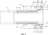
фиг. 1 - гидравлическое запрессовочное устройство, содержащее болтовой элемент, подлежащий фиксации на болтовом элементе инструмент и выполненную с возможностью блокирования гайку быстрой замены, в изометрической проекции, частично в разнесенной изометрической проекции;FIG. 1 is a hydraulic press-fit device containing a bolt element to be fixed on a bolt element and made with the possibility of blocking a quick-change nut, in an isometric view, partially in an exploded isometric view;
фиг. 2 - болтовой элемент с насаженной гайкой;FIG. 2 - a bolt element with a mounted nut;
фиг. 3 - разрез предмета, согласно фиг. 2, по линии III-III;FIG. 3 is a sectional view of an object according to FIG. 2, along line III-III;
фиг. 4 - разрез, согласно фиг. 3, однако при повернутых относительно друг друга первой и второй части гайки, при этом гайка находится в положении блокирования;FIG. 4 is a section according to FIG. 3, however, when the first and second parts of the nut are rotated relative to each other, while the nut is in the locked position;
фиг. 5 - разрез, согласно фиг. 4, однако в зоне размыкающей детали;FIG. 5 is a section according to FIG. 4, however, in the area of the trip part;
фиг. 6 - другой разрез установленной на болте гайки в повернутом положении, при этом разрез проходит по зонам резьбы гайки;FIG. 6 is another section of a nut mounted on a bolt in a rotated position, wherein the section passes through the thread zones of the nut;
фиг. 7 - гайка и соответствующий болт, в разнесенной изометрической проекции;FIG. 7 - nut and corresponding bolt, in an exploded isometric view;
фиг. 8 - изображение как на фиг. 7, однако косо снизу;FIG. 8 is an image as in FIG. 7, however obliquely from below;
фиг. 9 - разрез предмета, согласно фиг. 2, по линии IX-IX;FIG. 9 is a sectional view of an object according to FIG. 2, along the line IX-IX;
фиг. 10 - изображение как на фиг. 9 в повернутом положении;FIG. 10 is an image as in FIG. 9 in a rotated position;
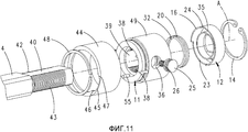
фиг. 11 - изображение как на фиг. 8 для другого варианта выполнения;FIG. 11 is an image as in FIG. 8 for another embodiment;
фиг. 12 - разрез установленной на болт гайки, согласно показанному на фиг. 11 варианту выполнения, в положении разъединения;FIG. 12 is a sectional view of a bolt-mounted nut as shown in FIG. 11 embodiment, in the disconnect position;
фиг. 13 - разрез предмета, согласно фиг. 12, по линии XIII-XIII;FIG. 13 is a sectional view of an object according to FIG. 12, along the lines XIII-XIII;
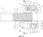
фиг. 14 - изображение как на фиг. 12 в повернутом положении; фиг. 15 - разрез предмета, согласно фиг. 14, по линии XV-XV; фиг. 16 - болт и профилирования, соответственно, витки резьбы на болте, в увеличенном масштабе.FIG. 14 is an image as in FIG. 12 in a rotated position; FIG. 15 is a sectional view of an object according to FIG. 14, along the line XV-XV; FIG. 16 - bolt and profiling, respectively, the threads on the bolt, on an enlarged scale.
Сначала ниже приводится описание со ссылками на фиг. 1 электрогидравлического ручного прибора 1, который в не показанной здесь подробно части выполнен, например, в соответствии с US 7 421 877 В2, при этом, однако, вместо рабочего поршня, который подвижно размещен в цилиндре, с соединенным с насосным поршнем напорным трубопроводом соединен свободно стоящий гидравлический трубопровод 2, который входит в цилиндр 3, в котором расположен движущийся назад относительно рабочего хода поршень, с помощью которого может оттягиваться назад болт 4.First, a description is given below with reference to FIG. 1 of an electro-hydraulic hand-held
С помощью такого инструмента можно, например, вырезать в металлическом листе 5 отверстие с помощью штамповочного инструмента 6 и контропоры 7. Контропора 7, соответственно, направляется над болтом 4 и может прилегать к буртику 8 болта. После этого болт направляется через уже имеющееся отверстие 9 в металлическом листе 5, а затем на задней стороне металлического листа 5 на болт 4 надвигается инструмент 6, а затем гайка 10 и в надвинутом состоянии блокируется за счет поворота вокруг оси болта. При этом достигается блокирование, как будет пояснено ниже, при этом, например, выдвигается размыкающая деталь 25.Using such a tool, it is possible, for example, to cut a hole in the
Состояние блокирования гайки 10 на болте 4 показано на фиг. 2. Гайка находится относительно болта в повернутом положении.The locking state of the
Ниже приводится пояснение конструкции гайки и блокирования со ссылками на фиг. 3-10. На фиг. 3 штриховыми линиями также показано, что относящиеся к гайке варианты выполнения могут быть выполнены также в пластинчатой части.The following is an explanation of nut design and blocking with reference to FIG. 3-10. In FIG. 3 also shows in dashed lines that the nut-related embodiments can also be made in the plate part.
Гайка 10 имеет первую часть 11 с первым сквозным отверстием O1 (см., например, фиг. 8) и вторую часть 12 со сквозным отверстием O2 (см. также фиг. 7).The
Отверстие O2 имеет ограниченный краевой кромкой 13 контур отверстия. Контур второго отверстия O2 не круглый. В частности, в показанном примере выполнения отверстие O2 выполнено с прямоугольным контуром отверстия, при этом длинные стороны выполнены прямолинейными, а узкие стороны вогнуто закруглены.The hole O 2 has a hole contour bounded by a
Ось А вращения проходит через оба отверстия O1, O2. Предпочтительно и как реализовано в примере выполнения, ось А вращения является общей осью вращения первой части 11 и второй части 12. Ось А вращения предпочтительно является также средней осью первой части 11 и/или второй части 12.The axis of rotation A passes through both holes O 1 , O 2 . Preferably and as implemented in the exemplary embodiment, the rotation axis A is the common rotation axis of the
Части 11, 12 соединены друг с другом с возможностью поворота.
Для поворотного соединения обеих частей 11, 12, вторая часть 12 вставлена в первую часть 11. А именно, предусмотрено удерживание с геометрическим замыканием второй части в первой части. В примере выполнения это обеспечивается предпочтительно с помощью пружинного стопорного кольца 14, которое входит в затыловку 15 первой части 11. Окружная поверхность гайки образована самой гайкой 10, за исключением, возможно, размыкающей детали 25.For the rotary connection of both
Вторая часть 12 имеет первую стенку 16, которая проходит внутри наружной стенки 17 первой части 11. Первая стенка 16 предпочтительно обеспечивает поворотную направляющую второй части 12 на первой части 11.The
Кроме того, как предусмотрено в примере выполнения, вторая часть 12 может иметь вторую стенку 18, которая проходит относительно первой стенки 16 с радиальным смещением внутрь. Первая стенка 16 и/или вторая стенка 18 проходит предпочтительно в направлении оси А, особенно предпочтительно параллельно ей. Между первой стенкой 16 и второй стенкой 18 оставлено открытое вниз, т.е. обращенное, например, к зоне профилирования первой части 11 промежуточное пространство 19. Первая стенка 16 и вторая стенка 18 предпочтительно расположены концентрично друг другу и предпочтительно выполнены каждая круглой в плане. Стенки 16 и 18 соединены друг с другом U-образно с помощью перемычки 21. Перемычка 21 выполнена на верхней стороне ступенчатой. Ступенька предпочтительно открыта радиально наружу. Предпочтительно, на нижней поверхности 22 ступеньки сидит пружинное стопорное кольцо 14. Как показано, например, на фиг. 8, первая стенка 16 второй части 12 предпочтительно профилирована на нижней стороне. Первая стенка 16 имеет, например, окружной вырез 23. Кроме того, имеет предпочтительно выемку 24 позиционирования.In addition, as provided in the exemplary embodiment, the
Окружная выемка 23 может служить для ограничения угла поворота второй части 12 относительно первой части 11. Выемка 24 позиционирования предпочтительно обеспечивает возможность перемещения размыкающей детали 25 в повернутом положении, соответственно, положении блокирования из вдвинутого положения, согласно фиг. 3, в выдвинутое положение, согласно фиг. 5. Для этого размыкающая деталь 25 подпружинена наружу с помощью пружины 26 сжатия относительно находящейся радиально внутри с перекрытием стенки 27 первой части 11.The
Выдвигание размыкающей детали 25 в повернутом положении, за счет которого обеспечивается блокирование, как предусмотрено в примере выполнения, имеет также преимущество индикатора. В частности, тактильно обнаруживаемого индикатора.The extension of the
Для перемещения из положения блокирования, согласно фиг. 5, в котором гайка фиксирована на болте без возможности снятия, снова в положение разъединения, показанное на фиг. 3, необходимо в показанном на фиг. 1-10 примере выполнения нажать на размыкающую деталь 25 радиально внутрь против действия пружины 26. На основании имеющегося в положении блокирования, согласно фиг. 5, вследствие сжатия пружины 20 предварительного напряжения частей 11 и 12 относительно друг друга, первая часть почти самостоятельно поворачивается в положение разъединения, согласно фиг. 3, при нажатии на размыкающую деталь 25 в положении на фиг. 5 относительно второй части 12 снова в положение, согласно фиг. 3.To move from the blocking position according to FIG. 5, in which the nut is fixed on the bolt without the possibility of removal, again to the disconnection position shown in FIG. 3 is necessary in FIG. 1-10 of the exemplary embodiment, press the
Возможность ограниченного поворота первой части 11 относительно второй части 12 за счет окружной выемки 23 предпочтительно дополнительно обеспечивается с помощью соединенной без возможности проворачивания с первой частью 11 или сформированной по-другому на первой части 11 упорной части 28.The possibility of a limited rotation of the
Пружина 20 закреплена как на первой части 11, так и на второй части 12. Предпочтительно, с одной стороны, пружина 20 закреплена на второй части 12 с помощью входящего в отверстие 29 второй части 12 конца 30 и, с другой стороны, пружина 20 закреплена на первой части 11 с помощью входящего в отверстие 31 первой части 11 конца 32. Как показано, в частности, на фиг. 6, первая часть 11 образует сверху обращенную ко второй части 12 кольцеобразную окружную выемку 33. На плоское дно 34 выемки 33 опирается нижняя поверхность 35 стенки 16 второй части 12, за исключением зоны окружного отверстия 23 и выемки 24 позиционирования.The
В выемку 33 выступает в примере выполнения образованный цапфой 55 упор 28. In the
Выемка 33 переходит в зоне размыкающей детали 25 в круглую выемку 36, которая проходит также через примыкающую над дном 34 выемки 33 зону 37 стенки первой части 11. Круглая выемка 36 выполнена с проходящей в радиальном направлении средней осью.The
Первая часть 11 имеет на внутренней стороне профилирование, предпочтительно резьбовые выточки 38. Речь идет о двух выполненных противоположно друг другу резьбовых выточках 38, которые прерваны не имеющей резьбы поверхностью 39, а именно, соответственно, выполненными лежащими противоположно друг другу поверхностями. Поверхность 39 проходит по соответствующему основанию резьбы 38 диаметру. Резьбовые выточки 38 или другие профилирования, как указывалось выше, предпочтительно выполнены, исходя из цилиндрической основной поверхности. Предпочтительно, радиально внутреннее ограничение резьбы также задано цилиндрической поверхностью, возможно, за исключением предусмотренной на стороне конца выточки уплощения или закругления, как будет пояснено ниже.The
Болт 4 имеет, как показано, в частности, на фиг. 9 и 10, по существу прямоугольное поперечное сечение с двумя противоположно лежащими, не имеющими профилирования сторонами 40, 41 и двумя профилированными, имеющими в примере выполнения резьбовые выточки сторонами 42, 43. В то время как стороны 40, 41 поперечного сечения выполнены прямолинейными, снабженные резьбой стороны 42, 43 выполнены с проходящим по круговой линии контуром.The
Профилирования болта, соответственно, гайки, в частности резьбовые выточки, выполнены дополняющими друг друга. Размеры выбраны так, что обеспечивается возможность непосредственного зацепления друг с другом в смысле резьбы и противоположной резьбы.Profiling the bolt, respectively, nuts, in particular threaded grooves, are complementary. The dimensions are selected so that it is possible to directly engage with each other in the sense of thread and opposite thread.
На фиг. 11 показан другой вариант выполнения.In FIG. 11 shows another embodiment.
Этот другой вариант выполнения отличается от указанного выше варианта выполнения, в частности, дополнительно расположенной на первой части поворотной втулкой 44. Эта поворотная втулка 44 обеспечивает фиксацию в повернутом положении гайки за счет поворота поворотной втулки в положение фиксации. В положении фиксации, также как в указанном выше варианте выполнения, расположенная в данном случае внутри поворотной втулки 44 размыкающая деталь 25 перемещается наружу, также здесь под действием пружины 26, и тем самым фиксирует повернутое положение тем же образом, как и в указанном выше варианте выполнения.This other embodiment differs from the aforementioned embodiment, in particular, the
Поворотная втулка 44 имеет то преимущество, что гайку можно свободно захватывать по всей её окружности для перемещения из положения разъединения в повернутое положение.The
Поворотная втулка 44 имеет на внутренней стороне выемку 45, которая в примере выполнения выполнена в виде уменьшения толщины стенки поворотной втулки 44. Выемка 45 имеет в поперечном сечении, т.е. с прохождением в окружном направлении, как показано на фиг. 13, закругленные или скошенные концевые зоны 46, 47, которые при повороте обеспечивают возможность отжимания вниз размыкающей детали 25 из положения согласно фиг. 15 в положение согласно фиг. 13.The
Поворотная втулка 44 зафиксирована с возможностью поворота, однако без возможности спадания на первой части 11. В показанном примере выполнения это осуществляется с помощью пружинного стопорного кольца 48.The
Кроме того, поворотная втулка установлена с возможностью лишь ограниченного по углу поворота относительно первой части 11. Ограничение по углу достигается, например, с помощью пальца 49, который частично выступает в выемку 45 и взаимодействует здесь, соответственно, со скосами 46 или 47.In addition, the rotary sleeve is installed with the possibility of only a limited angle of rotation relative to the
В остальном заданы те же соотношения, что и в указанном выше варианте выполнения.Otherwise, the same ratios are set as in the above embodiment.
На фиг. 16, включая также изображенную в увеличенном масштабе часть, показано уплощение на витке резьбы или в принципе профилирования, в данном случае на болте 4, а также штриховыми линиями в увеличенном масштабе на гайке. Уплощение служит для более легкого введения профилирований друг в друга при повороте в положение блокирования. Как показано на фигуре, одна торцевая поверхность витка 50 резьбы болта выполнена не в соответствии с радиальной прямой и тем самым перпендикулярной окружному направлению плоскостью, а с плоско выбегающей в окружающий материал 51 торцевой поверхностью 52. В показанном примере выполнения резьба имеет также торцевую кромку или торцевую поверхность 53. Эта торцевая кромка 53 выполнена на концевом участке 54 с наклонным уплощением.In FIG. 16, including also an enlarged part, shows flattening on a thread or in principle a profiling, in this case on a
Предпочтительно, гайка не имеет особой формы, или же предусмотрена лишь соответствующая плоская торцевая поверхность 52'. Однако возможно предусмотрение также в данном случае спадающего участка 54' соответствующей торцевой кромки 53'.Preferably, the nut is not particularly shaped, or only a corresponding flat end surface 52 'is provided. However, it is also possible to provide in this case a falling section 54 ′ of the corresponding end edge 53 ′.
Существенным является то, что размеры всегда выбираются так, что все еще получается явное перекрытие а (с наклонно спадающим участком 54' в гайке), соответственно, b (без наклонно спадающего участка 54' в гайке) между торцевыми кромками резьбы.It is essential that the dimensions are always chosen so that an explicit overlap of a (with an inclined section 54 'in the nut), respectively, b (without an inclined section 54' in the nut) between the thread end edges is still obtained.
Claims (8)
Applications Claiming Priority (3)
| Application Number | Priority Date | Filing Date | Title |
|---|---|---|---|
| DE102010036482.7 | 2010-07-19 | ||
| DE102010036482A DE102010036482A1 (en) | 2010-07-19 | 2010-07-19 | Nut and combination of a bolt part with a nut |
| PCT/EP2011/061475 WO2012019832A1 (en) | 2010-07-19 | 2011-07-07 | Nut and combination of a bolt part and a nut |
Publications (2)
| Publication Number | Publication Date |
|---|---|
| RU2013107024A RU2013107024A (en) | 2014-08-27 |
| RU2563780C2 true RU2563780C2 (en) | 2015-09-20 |
Family
ID=44628507
Family Applications (1)
| Application Number | Title | Priority Date | Filing Date |
|---|---|---|---|
| RU2013107024/12A RU2563780C2 (en) | 2010-07-19 | 2011-07-07 | Nut and combination of bolt element and nut |
Country Status (14)
| Country | Link |
|---|---|
| US (1) | US9255601B2 (en) |
| EP (2) | EP2728210B1 (en) |
| KR (1) | KR101998332B1 (en) |
| CN (1) | CN103026080B (en) |
| AU (1) | AU2011288986B2 (en) |
| BR (1) | BR112013001361A2 (en) |
| DE (1) | DE102010036482A1 (en) |
| DK (1) | DK2596254T3 (en) |
| ES (1) | ES2472462T3 (en) |
| MX (1) | MX2013000381A (en) |
| PL (1) | PL2596254T3 (en) |
| PT (1) | PT2596254E (en) |
| RU (1) | RU2563780C2 (en) |
| WO (1) | WO2012019832A1 (en) |
Families Citing this family (10)
| Publication number | Priority date | Publication date | Assignee | Title |
|---|---|---|---|---|
| DE102010036482A1 (en) | 2010-07-19 | 2012-01-19 | Gustav Klauke Gmbh | Nut and combination of a bolt part with a nut |
| DE102010061321A1 (en) | 2010-12-17 | 2012-06-21 | Gustav Klauke Gmbh | Method for milling a recess in a workpiece and workpiece with a recess |
| DE102011052350A1 (en) | 2011-08-02 | 2013-02-07 | Gustav Klauke Gmbh | Pair of jaws for punching out holes |
| US9297404B2 (en) * | 2011-12-02 | 2016-03-29 | Honeywell International Inc. | Single tool installation/removal of restraint cable with anti-rotation feature |
| EP3322905A4 (en) * | 2015-07-14 | 2019-03-13 | Milwaukee Electric Tool Corporation | Quick connect mechanism for a draw stud assembly |
| US10532481B2 (en) | 2015-11-25 | 2020-01-14 | Ridge Tool Company | Punch tool system |
| JP7301346B2 (en) * | 2019-05-08 | 2023-07-03 | 株式会社佐原 | Hook member and tension spring |
| KR102361535B1 (en) * | 2020-01-29 | 2022-02-11 | 홍기 | Casing coupling structure of faucet for cold and hot water |
| US11851943B2 (en) * | 2021-02-19 | 2023-12-26 | Aborder Products, Inc. | Passage barrier |
| KR102444220B1 (en) * | 2021-11-02 | 2022-09-19 | 주식회사 지스 | Anti-loosening fastener for fuel cell stacks |
Citations (5)
| Publication number | Priority date | Publication date | Assignee | Title |
|---|---|---|---|---|
| SU1249213A1 (en) * | 1984-09-15 | 1986-08-07 | Ульяновское Головное Специальное Конструкторское Бюро Тяжелых И Фрезерных Станков | Rapid-action nut |
| EP0273863A1 (en) * | 1986-12-11 | 1988-07-06 | Geberit AG | Bolt and counter piece |
| US4781507A (en) * | 1987-08-13 | 1988-11-01 | Duenas Oswaldo A | Quick acting threaded fastener assembly |
| CN2444082Y (en) * | 2000-10-27 | 2001-08-22 | 李向华 | Screw nut for body building apparatus |
| EP2128461A1 (en) * | 2008-05-30 | 2009-12-02 | ALSTOM Technology Ltd | Nut locking system |
Family Cites Families (26)
| Publication number | Priority date | Publication date | Assignee | Title |
|---|---|---|---|---|
| US2736227A (en) * | 1956-02-28 | stroble | ||
| US1172669A (en) * | 1914-12-10 | 1916-02-22 | Frank R Caldwell | Nut-lock. |
| US1451970A (en) * | 1920-02-03 | 1923-04-17 | Constant J Kryzanowsky | Temporary fastening |
| US2138245A (en) * | 1937-10-30 | 1938-11-29 | David C Smith | Adjustable clamping tool |
| US2442064A (en) * | 1943-10-28 | 1948-05-25 | Glenn L Martin Co | Fastener |
| US2434876A (en) * | 1944-01-15 | 1948-01-20 | American Mach & Foundry | Cowl fastener |
| US2517364A (en) * | 1945-01-22 | 1950-08-01 | Carel T Torresen | Fastener adjuster |
| GB692041A (en) | 1950-07-04 | 1953-05-27 | Arthur Henry Eakins | Improvements relating to quick-acting screw fastening devices |
| US2742073A (en) * | 1952-06-20 | 1956-04-17 | Ernest D Iannetti | Quick attachable nut and bolt assembly |
| US2807854A (en) * | 1955-05-16 | 1957-10-01 | Richard A Mellen | Double nut fastener |
| US4418583A (en) * | 1981-07-06 | 1983-12-06 | The Bendix Corporation | Locking device |
| GB8313615D0 (en) | 1983-05-17 | 1983-06-22 | British Telecomm | Linkable rods |
| GB8517659D0 (en) * | 1985-07-12 | 1985-08-21 | Avdel Ltd | Self-plugging blind fastener |
| DE10216213A1 (en) | 2002-04-10 | 2003-10-23 | Klauke Gmbh Gustav | Electro-hydraulic pressing device and method for operating the same |
| FR2640180B1 (en) * | 1988-12-09 | 1991-03-29 | Framatome Sa | ADAPTER FOR SCREWING IN OR SCREWING THREADED CONNECTION ELEMENTS |
| CH680306A5 (en) * | 1990-02-05 | 1992-07-31 | Claude Jaggi | |
| US5156064A (en) * | 1991-05-21 | 1992-10-20 | Handy & Harman Automotive Group, Inc. | Cable length adjustment device |
| DE19701317A1 (en) | 1997-01-16 | 1998-07-23 | Peter Dipl Ing Renner | Leak recognition in fluid pipeline system |
| FR2762367B1 (en) | 1997-04-16 | 1999-06-04 | Rapid Sa | FIXING DEVICE FORMED FROM A SET OF TWO COOPERATING PARTS |
| DE19825132A1 (en) | 1998-06-05 | 1999-12-09 | Fischer Artur Werke Gmbh | Bolt thread for screw connection with bolt and nut |
| US6045188A (en) * | 1998-12-16 | 2000-04-04 | Schooler; Paul T. | Seat back lock |
| CN2454583Y (en) * | 2000-11-27 | 2001-10-17 | 上银科技股份有限公司 | Double nut fixing device |
| US7270509B2 (en) * | 2004-03-22 | 2007-09-18 | Universal Metal Products, Inc. | Fastener assembly |
| US7744322B2 (en) | 2005-09-29 | 2010-06-29 | Kaoru Taneichi | Nut |
| CN2900892Y (en) * | 2006-04-19 | 2007-05-16 | 常州世丰兴业工具有限公司 | Press button type telescopic rod |
| DE102010036482A1 (en) | 2010-07-19 | 2012-01-19 | Gustav Klauke Gmbh | Nut and combination of a bolt part with a nut |
-
2010
- 2010-07-19 DE DE102010036482A patent/DE102010036482A1/en not_active Withdrawn
-
2011
- 2011-07-07 EP EP14153016.2A patent/EP2728210B1/en active Active
- 2011-07-07 RU RU2013107024/12A patent/RU2563780C2/en not_active IP Right Cessation
- 2011-07-07 BR BR112013001361A patent/BR112013001361A2/en not_active Application Discontinuation
- 2011-07-07 PT PT117324160T patent/PT2596254E/en unknown
- 2011-07-07 WO PCT/EP2011/061475 patent/WO2012019832A1/en active Application Filing
- 2011-07-07 PL PL11732416T patent/PL2596254T3/en unknown
- 2011-07-07 US US13/809,672 patent/US9255601B2/en active Active
- 2011-07-07 CN CN201180035327.7A patent/CN103026080B/en not_active Expired - Fee Related
- 2011-07-07 AU AU2011288986A patent/AU2011288986B2/en not_active Ceased
- 2011-07-07 EP EP11732416.0A patent/EP2596254B1/en active Active
- 2011-07-07 ES ES11732416.0T patent/ES2472462T3/en active Active
- 2011-07-07 MX MX2013000381A patent/MX2013000381A/en active IP Right Grant
- 2011-07-07 KR KR1020137003994A patent/KR101998332B1/en active IP Right Grant
- 2011-07-07 DK DK11732416.0T patent/DK2596254T3/en active
Patent Citations (5)
| Publication number | Priority date | Publication date | Assignee | Title |
|---|---|---|---|---|
| SU1249213A1 (en) * | 1984-09-15 | 1986-08-07 | Ульяновское Головное Специальное Конструкторское Бюро Тяжелых И Фрезерных Станков | Rapid-action nut |
| EP0273863A1 (en) * | 1986-12-11 | 1988-07-06 | Geberit AG | Bolt and counter piece |
| US4781507A (en) * | 1987-08-13 | 1988-11-01 | Duenas Oswaldo A | Quick acting threaded fastener assembly |
| CN2444082Y (en) * | 2000-10-27 | 2001-08-22 | 李向华 | Screw nut for body building apparatus |
| EP2128461A1 (en) * | 2008-05-30 | 2009-12-02 | ALSTOM Technology Ltd | Nut locking system |
Also Published As
| Publication number | Publication date |
|---|---|
| CN103026080A (en) | 2013-04-03 |
| AU2011288986B2 (en) | 2014-07-10 |
| WO2012019832A1 (en) | 2012-02-16 |
| KR101998332B1 (en) | 2019-07-09 |
| DK2596254T3 (en) | 2014-08-25 |
| MX2013000381A (en) | 2013-03-05 |
| CN103026080B (en) | 2015-09-09 |
| EP2596254B1 (en) | 2014-05-21 |
| RU2013107024A (en) | 2014-08-27 |
| EP2728210B1 (en) | 2019-01-30 |
| ES2472462T3 (en) | 2014-07-01 |
| US9255601B2 (en) | 2016-02-09 |
| EP2728210A2 (en) | 2014-05-07 |
| PL2596254T3 (en) | 2014-09-30 |
| AU2011288986A1 (en) | 2013-01-24 |
| PT2596254E (en) | 2014-06-05 |
| EP2596254A1 (en) | 2013-05-29 |
| BR112013001361A2 (en) | 2016-05-17 |
| DE102010036482A1 (en) | 2012-01-19 |
| US20130202381A1 (en) | 2013-08-08 |
| KR20130128374A (en) | 2013-11-26 |
| EP2728210A3 (en) | 2014-09-10 |
Similar Documents
| Publication | Publication Date | Title |
|---|---|---|
| RU2563780C2 (en) | Nut and combination of bolt element and nut | |
| RU2662129C1 (en) | Temporary fastener | |
| US9782909B2 (en) | Draw stud connector | |
| US9246273B2 (en) | Rapid fixing device for rapid disconnection two-part connector | |
| US8967184B2 (en) | Locking fire hydrant | |
| EP3017204B1 (en) | Fastening element and fastening assembly | |
| RU2501993C2 (en) | Self-stopping threaded joint | |
| JP2014523829A5 (en) | ||
| CA2865679A1 (en) | A safety connecting device, in particular for piping, an end-coupler for such device, and a method for manufacturing a nut therefor | |
| CN108071656A (en) | Lock washer component | |
| CN105829028A (en) | Hydraulic tool | |
| WO2017059818A1 (en) | Quick installation joint | |
| KR20150010484A (en) | Nut for looseness prevention | |
| TWM481571U (en) | Mounting device | |
| CN113557380B (en) | Key structure | |
| EP2463487B1 (en) | Oil plug and oil plug receiver | |
| GB2423791A (en) | Removable post comprising shaft with bayonet coupling slot | |
| GB2456950A (en) | Removable post comprising shaft with bayonet coupling slot | |
| JP6525359B1 (en) | Nut anti-return device and detent nut having the same | |
| ITMI20110736A1 (en) | JUNCTION DEVICE FOR FURNITURE AND FURNITURE ARTICLES | |
| KR200311553Y1 (en) | locking device and tool for valve | |
| JP2015090214A (en) | Lock nut | |
| KR101714646B1 (en) | Nut For Assembling Gasket | |
| RU114909U1 (en) | DEVICE FOR PREVENTING AN UNAUTHORIZED THREADED CONNECTOR | |
| RU2398136C1 (en) | Facility for fixation of mutual angular position of two parts |
Legal Events
| Date | Code | Title | Description |
|---|---|---|---|
| MM4A | The patent is invalid due to non-payment of fees |
Effective date: 20190708 |