RU2551393C2 - Flow meter unit for drink preparation device - Google Patents
Flow meter unit for drink preparation device Download PDFInfo
- Publication number
- RU2551393C2 RU2551393C2 RU2012127369/28A RU2012127369A RU2551393C2 RU 2551393 C2 RU2551393 C2 RU 2551393C2 RU 2012127369/28 A RU2012127369/28 A RU 2012127369/28A RU 2012127369 A RU2012127369 A RU 2012127369A RU 2551393 C2 RU2551393 C2 RU 2551393C2
- Authority
- RU
- Russia
- Prior art keywords
- flow meter
- housing
- hook
- elements
- meter according
- Prior art date
Links
Images
Classifications
-
- A—HUMAN NECESSITIES
- A47—FURNITURE; DOMESTIC ARTICLES OR APPLIANCES; COFFEE MILLS; SPICE MILLS; SUCTION CLEANERS IN GENERAL
- A47J—KITCHEN EQUIPMENT; COFFEE MILLS; SPICE MILLS; APPARATUS FOR MAKING BEVERAGES
- A47J31/00—Apparatus for making beverages
- A47J31/44—Parts or details or accessories of beverage-making apparatus
-
- G—PHYSICS
- G01—MEASURING; TESTING
- G01F—MEASURING VOLUME, VOLUME FLOW, MASS FLOW OR LIQUID LEVEL; METERING BY VOLUME
- G01F1/00—Measuring the volume flow or mass flow of fluid or fluent solid material wherein the fluid passes through a meter in a continuous flow
- G01F1/05—Measuring the volume flow or mass flow of fluid or fluent solid material wherein the fluid passes through a meter in a continuous flow by using mechanical effects
- G01F1/06—Measuring the volume flow or mass flow of fluid or fluent solid material wherein the fluid passes through a meter in a continuous flow by using mechanical effects using rotating vanes with tangential admission
- G01F1/075—Measuring the volume flow or mass flow of fluid or fluent solid material wherein the fluid passes through a meter in a continuous flow by using mechanical effects using rotating vanes with tangential admission with magnetic or electromagnetic coupling to the indicating device
-
- G—PHYSICS
- G01—MEASURING; TESTING
- G01F—MEASURING VOLUME, VOLUME FLOW, MASS FLOW OR LIQUID LEVEL; METERING BY VOLUME
- G01F15/00—Details of, or accessories for, apparatus of groups G01F1/00 - G01F13/00 insofar as such details or appliances are not adapted to particular types of such apparatus
- G01F15/14—Casings, e.g. of special material
-
- G—PHYSICS
- G01—MEASURING; TESTING
- G01F—MEASURING VOLUME, VOLUME FLOW, MASS FLOW OR LIQUID LEVEL; METERING BY VOLUME
- G01F15/00—Details of, or accessories for, apparatus of groups G01F1/00 - G01F13/00 insofar as such details or appliances are not adapted to particular types of such apparatus
- G01F15/18—Supports or connecting means for meters
- G01F15/185—Connecting means, e.g. bypass conduits
Abstract
Description
Область техники, к которой относится изобретениеFIELD OF THE INVENTION
Изобретение относится к узлу расходомеров, в частности расходомеров для устройств приготовления напитков.The invention relates to a flowmeter assembly, in particular flowmeters for beverage preparation devices.
В настоящем описании изобретения термин «напиток» включает в себя любые жидкие питательные напитки, такие как чай, кофе, горячий или холодный шоколад, молоко, суп, детское питание и т.п.As used herein, the term “beverage” includes any liquid nutritious beverage, such as tea, coffee, hot or cold chocolate, milk, soup, baby food, and the like.
Уровень техникиState of the art
В некоторых устройствах приготовления напитков используются капсулы, содержащие извлекаемые или растворяемые ингредиенты; в других устройствах ингредиенты хранятся в устройстве и автоматически дозируются или добавляются иным образом во время приготовления напитка.Some beverage preparation devices use capsules containing recoverable or soluble ingredients; in other devices, the ingredients are stored in the device and are automatically dosed or otherwise added during the preparation of the beverage.
Различные устройства приготовления напитков, такие как кофемашины, выполнены с возможностью подачи жидкости, обычно воды, находящейся в источнике, холодной или подогретой средствами подогрева, в смесительную или варочную камеру, где собственно происходит приготовление напитка за счет взаимодействия подаваемой жидкости с рассыпным или предварительно упакованным ингредиентом, например, находящимся внутри капсулы. Из подобной камеры приготовленный напиток обычно поступает в область раздачи напитка, например, на выпускное отверстие для напитка, расположенное над подставкой для чашки или кружки, являющееся частью или сопряженное с устройством приготовления напитков. Во время или после процесса приготовления использованные ингредиенты и/или их упаковка помещаются в накопительную емкость.Various beverage preparation devices, such as coffee machines, are capable of supplying a liquid, usually water in a source cold or heated by heating means, to a mixing or cooking chamber, where the beverage is actually prepared by the interaction of the supplied liquid with a loose or pre-packaged ingredient , for example, located inside the capsule. From such a chamber, the prepared beverage usually enters the beverage dispensing area, for example, to the beverage outlet located above the cup or mug stand, which is part of or paired with the beverage preparation device. During or after the cooking process, the ingredients used and / or their packaging are placed in a storage tank.
Большинство кофемашин оснащено средствами подачи, которые включают в себя помпу для жидкости, обычно воды, которая нагнетает жидкость из источника воды, холодной или подогретой средствами подогрева, например, терморезистором или т.п. Например, в US 5,943,472 раскрывается система циркуляции воды для подобной машины, расположенная между емкостью с водой и распределительной камерой для горячей воды или пара кофемашины для приготовления эспрессо. Система циркуляции включает в себя клапана, металлическую нагревательную трубку и помпу, которые соединены между собой, а также с емкостью при помощи множества силиконовых шлангов, скрепленных между собой хомутиками. В 2009/043865, WO 2009/074550, WO 2009/130099, а также РСТ/ЕР09/058562 раскрываются дополнительные средства подачи и соответствующие детали устройств приготовления напитков.Most coffee machines are equipped with dispensing means, which include a liquid pump, usually water, that pumps liquid from a water source, cold or heated by means of heating, for example, a thermistor or the like. For example, US 5,943,472 discloses a water circulation system for such a machine located between a water tank and a distribution chamber for hot water or steam of an espresso machine. The circulation system includes valves, a metal heating tube and a pump, which are connected to each other, as well as to the tank using a variety of silicone hoses, fastened together by clamps. In 2009/043865, WO 2009/074550, WO 2009/130099, as well as PCT / EP09 / 058562, additional supply means and corresponding details of the beverage preparation devices are disclosed.
Для управления параметрами жидкости, подаваемой в смесительную или варочную камеру, например, количеством и/или расходом, подобные установки обычно оснащаются расходомерами. Расходомеры, используемые в подобных устройствах приготовления напитков, изготовлены из материалов, разрешенных к использованию в пищевой промышленности, по меньшей мере, те их части, которые контактируют с циркулирующей текучей средой, а их использование в подобных установках должно быть экономически оправдано.To control the parameters of the liquid supplied to the mixing or cooking chamber, for example, the quantity and / or flow rate, such installations are usually equipped with flow meters. The flow meters used in such beverage preparation devices are made of materials approved for use in the food industry, at least those parts that are in contact with the circulating fluid, and their use in such installations should be economically justified.
В US 4,666,061 раскрывается расходомер для линий розлива вина, минеральной воды или пива, который легко может разбираться и собираться для проведения чистки. У расходомера имеется корпус, состоящий из двух элементов, скрепленных байонетным соединителем, внутри которого находится измерительная камера. В камере находится центрированный поворотный измерительный элемент с поворотным валом, удерживаемый по месту парой обращенных в сторону друг друга подшипников с алмазными наконечниками, которые установлены в корпусе и заходят в камеру. Недостатком данного устройства является стоимость подшипников с алмазными наконечниками, а также последовательность установки подобных подшипников с алмазными наконечниками в корпусе расходомера.US 4,666,061 discloses a flow meter for bottling lines of wine, mineral water or beer, which can be easily disassembled and collected for cleaning. The flowmeter has a housing consisting of two elements fastened with a bayonet connector, inside of which there is a measuring chamber. In the chamber there is a centered rotary measuring element with a rotary shaft, held in place by a pair of bearings facing each other with diamond tips, which are installed in the housing and enter the chamber. The disadvantage of this device is the cost of bearings with diamond tips, as well as the sequence of installation of such bearings with diamond tips in the body of the flowmeter.
В ЕР 0841547 раскрывается расходомер, предлагаемый на рынке фирмой DIGMESA, который подходит для использования в устройствах приготовления напитков. У подобного расходомера имеется корпус, состоящий из двух элементов, скрепленных байонетным соединением с четырьмя монтажными крюками, симметрично расположенными по окружности корпуса таким образом, чтобы они обеспечивали четыре сборочных положения для двух элементов корпуса и соответственно четыре положения для впускного и выпускного отверстий для воды расходомера, расположенных на двух элементах корпуса. В корпусе имеется внутренняя измерительная камера с проходящим через нее центральным неподвижным валом, на котором установлен внутренний поворотный измерительный элемент с ребрами, ребра расположены на пути следования потока и приводятся им в действие. Поток жидкости, проходящий через измерительную камеру, определяется скоростью вращения поворотного измерительного элемента, оснащенного датчиком Холла. Недостаток данного устройства заключается в большой площади фрикционной поверхности между неподвижным валом и вращающимся измерительным элементом, которая меняется в зависимости от расположения расходомера и которая также влияет на точность измерения потока, проходящего через камеру.EP 0841547 discloses a flow meter commercially available from DIGMESA that is suitable for use in beverage preparation devices. Such a flow meter has a housing consisting of two elements fastened by a bayonet connection with four mounting hooks symmetrically located around the circumference of the housing so that they provide four assembly positions for two housing elements and, accordingly, four positions for the inlet and outlet openings for the water flow meter, located on two elements of the housing. The housing has an internal measuring chamber with a central stationary shaft passing through it, on which an internal rotary measuring element with ribs is mounted, the ribs are located on the flow path and are driven by it. The fluid flow passing through the measuring chamber is determined by the speed of rotation of the rotary measuring element equipped with a Hall sensor. The disadvantage of this device is the large area of the friction surface between the fixed shaft and the rotating measuring element, which varies depending on the location of the flow meter and which also affects the accuracy of measuring the flow passing through the chamber.
Для некоторых областей применения бывает необходимо использовать нескольких байонетных монтажных крюков. Количество и размер монтажных крюков может зависеть от предполагаемого давления, при котором планируется использовать расходомер, а также от усилия затягивания, необходимого для обеспечения герметичности узла. Поэтому может потребоваться использование более одного или двух монтажных крюков, как это, например, раскрыто в ЕР 0841547. Между тем, существует всего лишь несколько областей применения, для которых приходиться менять компоновку подобного расходомера. В большинстве случаев, в течение всего срока эксплуатации расходомера используется одна и та же компоновка. Поэтому множество вариантов сборки может приводить лишь к ненужным ошибкам при сборке, поскольку подобные расходомеры допускают большее количество вариантов компоновки, чем это на самом деле требуется для их предполагаемого использования.For some applications, it may be necessary to use several bayonet mount hooks. The number and size of mounting hooks may depend on the expected pressure at which the meter is planned to be used, as well as on the tightening force necessary to ensure the tightness of the assembly. Therefore, it may be necessary to use more than one or two mounting hooks, as, for example, disclosed in EP 0841547. Meanwhile, there are only a few areas of application for which you have to change the layout of such a flow meter. In most cases, the same layout is used throughout the life of the flowmeter. Therefore, many assembly options can only lead to unnecessary assembly errors, since such flowmeters allow more configuration options than are actually required for their intended use.
Таким образом, по-прежнему существует потребность в простом, точном и недорогом расходомере, в частности, для использования в устройстве приготовления напитков.Thus, there remains a need for a simple, accurate and inexpensive flow meter, in particular for use in a beverage preparation device.
Раскрытие изобретенияDisclosure of invention
Изобретение, таким образом, относится к расходомеру, в частности для устройства приготовления напитков. Расходомер содержит корпус, ограничивающий измерительную камеру. Корпус состоит из первого элемента и второго элемента, собранных между собой при помощи байонетного соединителя, имеющего несколько пар соединительных крепежных деталей.The invention thus relates to a flowmeter, in particular for a beverage preparation device. The flow meter comprises a housing defining a measurement chamber. The housing consists of a first element and a second element, assembled together using a bayonet connector having several pairs of connecting fasteners.
После сборки усилие байонетного соединителя приходится на подобные соединительные крепежные детали. Они могут состоять из крюка, прохода для крюка и фиксатора крюка. Между тем, допустимы также и другие компоновки байонетных соединений, известные из уровня техники.After assembly, the force of the bayonet connector falls on such connecting fasteners. They may consist of a hook, a passage for the hook, and a hook lock. Meanwhile, other bayonet mount arrangements known in the art are also acceptable.
Согласно изобретению пары крепежных деталей расположены таким образом, чтобы первый и второй элементы могли скрепляться байонетным соединителем лишь в одном положении или в нескольких разных положениях, количество которых меньше количества пар соединительных крепежных деталей.According to the invention, the pairs of fasteners are arranged so that the first and second elements can be fastened with a bayonet connector in only one position or in several different positions, the number of which is less than the number of pairs of connecting fasteners.
Поэтому для выравнивания байонетного соединителя при сборке используются те же самые сопрягающиеся детали, которые воспринимают и обеспечивают механическое крепежное усилие при сборке байонетного соединителя и удерживают корпус расходомера в собранном положении. Обычно, для предварительного определения относительного положения элементов, соединяемых при помощи байонетного соединителя, никаких дополнительных деталей или ограничивающих узлов не требуется. В частности, для обеспечения правильной сборки расходомера не требуется никакой специальной маркировки или пометок на элементах корпуса или других деталях.Therefore, to align the bayonet connector during assembly, the same mating parts are used that absorb and provide mechanical fastening force when assembling the bayonet connector and hold the body of the flowmeter in the assembled position. Usually, for preliminary determination of the relative position of the elements connected by means of a bayonet connector, no additional parts or limiting units are required. In particular, to ensure the correct assembly of the flowmeter, no special marking or marking is required on the housing elements or other details.
И в первом и во втором элементах корпуса могут быть выполнены сквозные отверстия, сообщающиеся с измерительной камерой для циркуляции жидкости через подобный расходомер. Обычно подобные сквозные отверстия образуют впускное и выпускное отверстия расходомера. Относительное положение сквозных отверстий может зависеть от положения первого и второго элементов. Например, первое сквозное отверстие находится в первом элементе корпуса, а второе сквозное отверстие находится во втором элементе корпуса, сквозные отверстия, в частности, смещены относительно поворотной смыкающей оси байонетного соединителя. Поэтому относительные положения сквозных отверстий могут отличаться, в зависимости от сборочного положения байонетного соединителя, когда байонетный соединитель выполнен с возможностью сборки в разных положениях.And in the first and second elements of the housing can be made through holes communicating with the measuring chamber for circulating fluid through a similar flow meter. Typically, such through holes form the inlet and outlet of the flowmeter. The relative position of the through holes may depend on the position of the first and second elements. For example, the first through hole is in the first housing element, and the second through hole is in the second housing element, the through holes, in particular, are offset from the pivoting locking axis of the bayonet connector. Therefore, the relative positions of the through holes may vary, depending on the assembly position of the bayonet connector when the bayonet connector is configured to be assembled in different positions.
Разумеется, можно разместить крепежный узел на одном элементе корпуса, например, узел для установки расходомера в устройстве, а другой элемент, такой как сквозное отверстие, например, впускное или выпускное отверстие, либо разъем для датчика, такого как датчик Холла или электрического соединения, разместить на другом элементе корпуса, который должен быть определенным образом выровнен относительно крепежного узла. Существует множество факторов, почему сборочное положение байонетного соединителя должно быть заранее определено, в том числе форма внешнего корпуса расходомера, который должен быть совместим со средой, в которой устанавливается расходомер.Of course, you can place the mounting unit on one element of the housing, for example, a node for installing the flowmeter in the device, and another element, such as a through hole, for example, an inlet or outlet, or a connector for a sensor, such as a Hall sensor or an electrical connection, on another housing element, which must be aligned in a certain way with respect to the mounting unit. There are many factors why the assembly position of the bayonet connector must be predetermined, including the shape of the external housing of the flowmeter, which must be compatible with the environment in which the flowmeter is installed.
Крепежные детали могут быть выполнены за одно целое с соответствующими элементами корпуса, например, во время процесса формования.Fasteners can be made in one piece with the corresponding elements of the housing, for example, during the molding process.
По меньшей мере, одна пара соединительных крепежных деталей может содержать: на втором элементе корпуса - фиксатор крюка и проход для крюка, а на первом элементе корпуса - крюк, выполненный таким образом, чтобы он мог проходить через проход для крюка и зацепляться с фиксатором крюка после сборки байонетного соединителя; и/или на первом элементе корпуса - крюк и проход для фиксатора, а на втором элементе корпуса - фиксатор крюка, выполненный таким образом, чтобы он мог проходить через проход для фиксатора и зацепляться с крюком после сборки байонетного соединителя.At least one pair of connecting fasteners may contain: on the second housing element, a hook latch and a passage for the hook, and on the first housing element, a hook, made in such a way that it can pass through the passage for the hook and engage with the hook latch after bayonet connector assemblies; and / or on the first housing element, a hook and a passage for the latch, and on the second element of the housing, a hook latch made so that it can pass through the passage for the latch and engage with the hook after assembling the bayonet connector.
Обычно крепежные детали каждой пары имеют взаимодополняющую форму для их соединения между собой при сборке байонетного соединителя. Пары крепежных деталей одного байонетного соединителя могут иметь, по меньшей мере, два разных типа взаимодополняющих форм, выполненных таким образом, чтобы крепежная деталь пары первого типа была несовместима с соответствующей крепежной деталью другого типа.Typically, the fasteners of each pair have a complementary shape for their connection with each other when assembling the bayonet connector. The pairs of fasteners of one bayonet connector may have at least two different types of complementary shapes, made so that the fastener of the pair of the first type is incompatible with the corresponding fastener of another type.
Например, у пары соединительных крепежных деталей первого типа имеется крюк первого размера, который может соединяться с проходом для крюка и фиксатором крюка первого размера, а у пары соединительных крепежных деталей второго типа имеется крюк второго размера, который может соединяться с проходом для крюка и фиксатором крюка второго размера, крюк второго размера несовместим с проходом для крюка и/или фиксатором крюка первого размера, таким образом, чтобы первый крюк нельзя было установить во втором фиксаторе крюка. Крюк второго размера может быть больше прохода для крюка первого размера и/или может быть несовместим с фиксатором крюка. Такой же результат может быть достигнут при использовании прохода для фиксатора вместо или в дополнение к проходу для крюка.For example, a pair of connecting fasteners of a first type has a hook of a first size that can connect to a passage for a hook and a hook lock of a first size, and a pair of connecting fasteners of a second type has a hook of a second size that can connect to a passage for a hook and a hook lock of the second size, the hook of the second size is incompatible with the passage for the hook and / or the catch of the hook of the first size, so that the first hook cannot be installed in the second catch of the hook. The hook of the second size may be larger than the passage for the hook of the first size and / or may not be compatible with the hook latch. The same result can be achieved by using the lock passage instead of or in addition to the hook passage.
Пары крепежных деталей могут быть разнесены между собой и неравномерно распределены вдоль контактного участка между первым и вторым элементами.Pairs of fasteners can be spaced apart and unevenly distributed along the contact area between the first and second elements.
Корпус может состоять из двух составных, формованных элементов. По меньшей мере, какой-то один, первый или второй элемент корпуса, может иметь, в целом, чашеобразную форму. По меньшей мере, какой-то один, первый или второй элемент корпуса, может быть крышкой. На одном из элементов корпуса может быть буртик, а на другом элементе корпуса - уплотнительная кромка, при этом уплотнительная кромка устанавливается с натягом на буртик или, наоборот, для уплотнения первого и второго элементов, в частности для предотвращения протечек текучей среды, циркулирующей через расходомер во время его использования.The housing may consist of two composite, molded elements. At least one, first or second housing element may have a generally cup shape. At least one, first or second housing element may be a lid. There may be a collar on one of the housing elements, and a sealing lip on the other housing element, while the sealing lip is tightened on the collar or, conversely, to seal the first and second elements, in particular, to prevent leakage of fluid circulating through the flow meter during time of use.
Обычно в корпусе находится измерительный элемент, вращательно установленный в измерительной камере.Typically, a measurement element rotationally mounted in the measurement chamber is located in the housing.
Корпус и измерительный элемент могут быть изготовлены, по меньшей мере, из одного из следующих материалов: полиоксиметилена или полибутилентерефталата. Например, корпус и измерительный элемент изготовлены из полиоксиметилена, например из Schulaform 9A, и из полибутилентерефталата, например из Tecdur GK30, или наоборот.The housing and the measuring element can be made of at least one of the following materials: polyoxymethylene or polybutylene terephthalate. For example, the housing and the measuring element are made of polyoxymethylene, for example Schulaform 9A, and polybutylene terephthalate, for example Tecdur GK30, or vice versa.
Если расходомер используется в устройстве приготовления напитков, то материалы, из которых изготавливаются камера и вращающийся измерительный элемент, должны быть разрешены для использования в пищевой промышленности. Кроме этого, они должны иметь низкий коэффициент трения и низкий коэффициент истирания, а также обеспечивать точные допуски при изготовлении/формовании, позволяющие получить высококачественный расходомер, в частности имеющий повышенную надежность и низкую себестоимость. Кроме этого, подобные материалы должны обеспечивать такие допуски во время изготовления, например, формования, чтобы можно было получать небольшие по размеру детали, позволяющие уменьшить габариты расходомера, а также устройства, в которое подобный расходомер интегрируется для его эксплуатации. Вышеупомянутые материалы, в частности в комбинации, отвечают всем подобным требованиям.If the flowmeter is used in a beverage preparation device, the materials from which the chamber and the rotating measuring element are made must be approved for use in the food industry. In addition, they must have a low coefficient of friction and a low coefficient of abrasion, and also provide accurate tolerances in the manufacture / molding, allowing to obtain a high-quality flow meter, in particular having increased reliability and low cost. In addition, such materials must provide such tolerances during manufacture, for example, molding, so that it is possible to obtain small-sized parts that can reduce the dimensions of the flowmeter, as well as the device into which such a flowmeter is integrated for its operation. The above materials, in particular in combination, meet all similar requirements.
Коэффициент истирания полиоксиметилена о полибутилентерефталат составляет примерно 0.2 µm/км. Коэффициент истирания полибутилентерефталата о полиоксиметилен обычно составляет примерно 0.7 µm/км. Кроме этого, и полиоксиметилен, и полибутилентерефталат разрешены к использованию в пищевой промышленности. Подобный коэффициент истирания обеспечивает длительный период эксплуатации недорогих формованных расходомеров, например, для использования в устройствах приготовления напитков.The abrasion coefficient of polyoxymethylene about polybutylene terephthalate is approximately 0.2 μm / km. The abrasion coefficient of polybutylene terephthalate o polyoxymethylene is usually about 0.7 μm / km. In addition, both polyoxymethylene and polybutylene terephthalate are approved for use in the food industry. Such an attrition coefficient provides a long period of operation of inexpensive shaped flowmeters, for example, for use in beverage preparation devices.
Например, корпус и измерительный элемент могут содержать стабилизирующий наполнитель, такой как волокна или бусинки, в частности стеклянные бусинки, например стабилизирующий наполнитель занимает от 10 до 70% объема корпуса и/или измерительного элемента, в частности от 15 до 50% объема, например, от 20 до 40% объема. Использование наполнительного материала, такого как стеклянные бусинки и/или волокна позволяет лучше регулировать сжимание композитного материала во время отверждения на этапе формования. Это в частности желательно для обеспечения высокой пространственной точности относительно подвижных частей, а также для надлежащего соединения деталей. Кроме этого, использование соответствующего наполнителя обеспечивает чистоту поверхностей, в частности, подшипников, которые могут изготавливаться с малыми допусками. Наполнитель также позволяет уменьшить коэффициент трения и коэффициент истирания. Компоненты, изготавливаемые из подобных композитных материалов, также обладают высокой стабильностью, в частности это относится к соединительным деталям, рассматриваемым ниже. Дополнительные аспекты использования подобных материалов для изготовления расходомеров, раскрыты в ЕР 09163813.0, который включен здесь по ссылке.For example, the housing and the measuring element may contain a stabilizing filler, such as fibers or beads, in particular glass beads, for example, a stabilizing filler occupies from 10 to 70% of the volume of the housing and / or measuring element, in particular from 15 to 50% of the volume, for example from 20 to 40% of the volume. The use of filler material, such as glass beads and / or fibers, allows better control of the compression of the composite material during curing in the molding step. This is particularly desirable for ensuring high spatial accuracy with respect to moving parts, as well as for proper connection of parts. In addition, the use of an appropriate filler ensures the cleanliness of surfaces, in particular bearings, which can be manufactured with low tolerances. The filler also allows to reduce the coefficient of friction and the coefficient of abrasion. Components made from such composite materials also have high stability, in particular this applies to the connecting parts, discussed below. Additional aspects of the use of such materials for the manufacture of flowmeters are disclosed in EP 09163813.0, which is incorporated herein by reference.
По одному из вариантов осуществления у поворотного измерительного элемента имеется поворотный вал, проходящий сквозь измерительную камеру, вал установлен с возможностью вращения и выровнен на противоположных крайних точках измерительной камеры при помощи точечных подшипников. Например, вал является ротором или аналогичным элементом, детали которого, такие как ребра или лопасти, обычно крыльчатка, взаимодействуют с потоком. Каждый точечный подшипник может состоять из выступающей части и ответной, противолежащей сопрягаемой части, в частности, углубленной части, сопрягаемой, соответственно с корпусом и крайней точкой поворотного вала, либо наоборот. Выступающая часть и ответная часть предпочтительно цельноформованы с сопряженными с ними формованным корпусом и формованным поворотным валом.According to one embodiment, the rotary measuring element has a rotary shaft passing through the measuring chamber, the shaft is rotatably mounted and aligned at opposite extreme points of the measuring chamber by means of point bearings. For example, the shaft is a rotor or similar element, the details of which, such as ribs or blades, usually an impeller, interact with the flow. Each point bearing can consist of a protruding part and a reciprocal, opposite opposite mating part, in particular, a recessed part mating, respectively, with the housing and the extreme point of the rotary shaft, or vice versa. The protruding part and the reciprocal part are preferably integrally molded with the associated molded body and the molded rotary shaft.
Например, корпус содержит противолежащие выступы, заходящие в камеру и образующие точечные подшипники. Как вариант, выступы могут быть расположены на валу измерительного элемента. Также можно использовать смешанную компоновку, т.е. первый подшипник с выступом на валу, а второй (противоположный) подшипник с выступом на корпусе.For example, the housing contains opposing protrusions extending into the chamber and forming point bearings. Alternatively, the protrusions may be located on the shaft of the measuring element. You can also use a mixed layout, i.e. the first bearing with a protrusion on the shaft, and the second (opposite) bearing with a protrusion on the housing.
У поворотного вала обычно имеется ось вращения, проходящая между точечным подшипником, расположенным на втором элементе корпуса, например, крышке, и противолежащим точечным подшипником, расположенным на первом элементе корпуса, например, чашеобразном элементе корпуса.A rotary shaft typically has a rotational axis extending between a point bearing located on a second housing element, such as a cover, and an opposing point bearing located on a first housing element, such as a bowl-shaped housing element.
Первый элемент корпуса может образовывать базовую поверхность, проходящую перпендикулярно оси вращения вала, у второго элемента имеется внутренняя поверхность, которая прижимается к базовой поверхности, например, к вышеупомянутому контактному участку, для точного установления зазора между подобными точечными подшипниками таким образом, чтобы они удерживали и обеспечивали свободное вращение находящегося между ними вала. Подобное геометрическое выравнивание, позволяющее создать гарантированный точный зазор между точечными подшипниками, обеспечивается за счет использования байонетной смыкающей системы между первым и вторым элементами.The first housing element can form a base surface extending perpendicular to the axis of rotation of the shaft, the second element has an inner surface that is pressed against the base surface, for example, to the aforementioned contact area, to accurately establish the gap between such point bearings so that they hold and provide free rotation of the shaft located between them. Such geometric alignment, which allows you to create a guaranteed accurate clearance between the point bearings, is achieved through the use of a bayonet locking system between the first and second elements.
Таким образом, производственная себестоимость подобного расходомера, который не требует использования алмазов или аналогичных материалов для изготовления подшипников, существенно снижена. Две детали подшипников могут быть изготовлены на этапе формования компонентов, с которыми они непосредственно сопрягаются. Детали подшипников могут быть неразъемно сформованы с неподвижным опорным компонентом, а также с подвижным измерительным компонентом, соответственно, поэтому никаких дополнительных этапов сборки не требуется. Это существенно снижает производственную себестоимость. При этом точность показаний расходомера по большому счету не зависит от расположения расходомера. Выступающая часть и/или ответная часть каждого точечного подшипника могут изготавливаться из расплавляемых/отверждаемых и/или полимеризируемых материалов, обычно за счет формования подобных материалов.Thus, the production cost of such a flowmeter, which does not require the use of diamonds or similar materials for the manufacture of bearings, is significantly reduced. Two parts of bearings can be made at the stage of forming the components with which they are directly mated. Bearing parts can be permanently molded with a stationary support component, as well as with a movable measuring component, respectively, therefore, no additional assembly steps are required. This significantly reduces production costs. In this case, the accuracy of the flow meter readings by and large does not depend on the location of the flow meter. The protruding part and / or the reciprocal part of each point bearing can be made of molten / curable and / or polymerizable materials, usually by molding such materials.
Дополнительные необязательные конструктивные элементы подобного расходомера, раскрыты, например, в ЕР 09163815.5, который включен здесь по ссылке. Например, корпус может включать в себя соединительный узел для неразъемного соединения с ним датчика, в частности датчика Холла.Additional optional structural elements of such a flow meter are disclosed, for example, in EP 09163815.5, which is incorporated herein by reference. For example, the housing may include a connecting unit for permanently connecting with it a sensor, in particular a Hall sensor.
Изобретение также относится к устройству приготовления напитков, оснащенному контуром циркуляции жидкости, в частности контуром циркуляции воды, содержащему расходомер, рассмотренный выше.The invention also relates to a beverage preparation device equipped with a liquid circulation circuit, in particular a water circulation circuit comprising a flowmeter as discussed above.
Например, устройство является устройством для приготовления кофе, чая или супа, в частности устройством для приготовления внутри варочного блока напитка за счет пропускания горячей или холодной воды или другой жидкости через капсулу или контейнер с ингредиентом приготовляемого напитка, таким как молотый кофе или чай или шоколад или какао или сухое молоко. Устройство может содержать варочный блок, в котором находится подобный ингредиент. Обычно устройство включает в себя один или несколько следующих элементов: насос, нагреватель, поддон, емкость для ингредиентов, емкость для жидкости, а также систему подачи текучей среды для подачи текучей среды из емкости для жидкости в варочный бак и т.п. Компоновка контура текучей среды, расположенного между емкостью для жидкости и нагревателем подобного устройства, например, более подробно раскрыта в WO 2009/074550.For example, the device is a device for making coffee, tea or soup, in particular a device for preparing a beverage inside the brewing unit by passing hot or cold water or other liquid through a capsule or container with an ingredient of a prepared beverage, such as ground coffee or tea or chocolate or cocoa or milk powder. The device may comprise a cooking unit in which a similar ingredient is located. Typically, a device includes one or more of the following elements: a pump, a heater, a pan, an ingredient container, a liquid container, and a fluid supply system for supplying fluid from a liquid container to a cooking tank or the like. An arrangement of a fluid circuit located between a liquid container and a heater of such a device, for example, is described in more detail in WO 2009/074550.
Краткое описание чертежейBrief Description of the Drawings
Далее изобретение будет описано подробнее со ссылкой на схематические чертежи.The invention will now be described in more detail with reference to the schematic drawings.
На фиг.1 показано изображение в разобранном виде расходомера по изобретению;Figure 1 shows an exploded view of a flowmeter according to the invention;
на фиг.2 - вид сверху другого расходомера по изобретению;figure 2 is a top view of another flowmeter according to the invention;
на фиг.3а и 3b - вид сверху другого расходомера по изобретению, при этом расходомер показан в двух разных сборочных компоновках.on figa and 3b is a top view of another flowmeter according to the invention, while the flow meter is shown in two different assembly layouts.
Осуществление изобретенияThe implementation of the invention
На фиг.1 показан расходомер 1, обычно используемый в устройстве приготовления напитков, таком как кофемашина. Расходомер может устанавливаться в контуре текучей среды устройства приготовления напитков как это, например, более подробно рассмотрено в WO 2009/130099.1 shows a
У расходомера 1 имеется корпус, состоящий из двух собранных формованных элементов 2, 4, которые ограничивают внутреннюю, в целом, цилиндрическую измерительную камеру 10. Например, корпус изготавливается методом литья под давлением.The
В каждом из формованных элементов 2, 4 имеется сквозное отверстие, сообщающееся с измерительной камерой 10, для обеспечения циркуляции жидкости через подобный расходомер. В частности, в чашеобразном элементе 4 имеется трубчатое впускное отверстие 47, а в крышке 2 имеется трубчатое выпускное отверстие 27. Разумеется, впускное и выпускное отверстия могут меняться местами. Кроме этого, впускное и выпускное отверстия могут находиться на одном и том же формованном элементе. Относительное положение подобных впускного и выпускного отверстий зависит от положения первого и второго элементов.In each of the molded
В корпусе 2, 4 имеется вращающийся измерительный элемент 3 в виде ротора или крыльчатки. У элемента 3 имеется несколько радиальных элементов 31, например, ребер или лопастей, установленных на поворотном валу 32, проходящем через центр измерительной камеры 10. У вала 32 имеется нижняя часть 33, от которой отходят радиальные элементы 31, а также верхняя часть 34. В верхней части 34 имеются две полости 35 для пары магнитов 36 соответствующей формы. Вал 32 или элемент 3 также могут быть изготовлены методом литья под давлением.In the
У расходомера 1 имеются верхний и нижний точечные подшипники, на которые опираются противоположные крайние точки 32', 32” поворотном валу 32 внутри элементов 2, 4 корпуса. Подобные точечные подшипники образованы выступами на корпусе 2, 4, заходящими в камеру 10, а также углублениями в крайних точках 32', 32” поворотного вала 32, являющимися ответными частями для выравнивания выступов, нижний выступ в виде штыря 11, а также верхняя выемка 37 подобного типа, являющиеся частями нижнего и верхнего подшипников, показаны на фиг.1. Нижний и верхний подшипники идентичны и обладают схожей функциональностью при любом расположении.The
Выступы 11 и ответные части 37 неразъемно соединены с формованными элементами 2, 4 корпуса и поворотным валом 32, соответственно. Другими словами, никаких дополнительных элементов для получения деталей подшипников расходомера не требуется. Они могут быть сформованы непосредственно с соответствующими элементами, т.е. с элементами 2, 4 корпуса и валом 32. Вал или даже вся крыльчатка 3 (кроме магнитов 36) могут быть изготовлены из полиоксиметилена, а корпус 2, 4, 30% объема которого занимают стеклянные шарики, используемые в качестве наполнителя, может быть изготовлен из полибутилентерефталата.The protrusions 11 and the mating parts 37 are inseparably connected with the molded
Как показано на фиг.1, нижний элемент 4 корпуса, в целом, имеет форму чаши, а верхний элемент 2 корпуса, в целом, имеет форму крышки. Следует понимать, что понятия «нижний» и «верхний» относятся исключительно к конкретному положению расходомера 1, показанному на фиг.1. Во время эксплуатации расходомер 1 может находиться в любом, даже измененном положении.As shown in FIG. 1, the
Поворотный вал 32 имеет ось 3' вращения, проходящую от точечного подшипника (не показан), расположенного в крышке 2, до противолежащего точечного подшипника 11, расположенного в чашеобразном элементе 4.The rotary shaft 32 has a rotation axis 3 ′ extending from a point bearing (not shown) located in the
У чашеобразного элемента 4 имеется буртик 41, образующий базовую поверхность 42, проходящую перпендикулярно оси вращения, а у крышки 2 имеется внутренняя поверхность 22, которая прижимается к базовой поверхности 42 для выставления прецизионного зазора между точечными подшипниками 11 таким образом, чтобы они удерживали и обеспечивали свободное вращение находящегося между ними вала 32. Внутренняя поверхность 22 и базовая поверхность 42 образуют контактный участок 22, 42 байонетного соединителя.The cup-shaped
Кроме этого, у буртика 41 имеется вертикальная внутренняя поверхность 43, сопрягающаяся с соответствующей уплотнительной кромкой 23 крышки 2 для уплотнения крышки 2 с чашеобразным элементом 4 за счет глухой посадки кромки 23 на буртик 41. Подобный узел и возможные варианты рассмотрены более подробно в документах ЕР 09 163 815.5 и ЕР 09163813.0.In addition, the flange 41 has a vertical inner surface 43, mating with the corresponding sealing edge 23 of the
У чашеобразного элемента 4 имеются четыре разнесенных крюка 45, 45а, которые, в целом, равномерно распределены по буртику 41 и контактному участку 22, 42 и которые сопрягаются с соответствующими проходами 25, 25а и фиксаторами 26 крюков по окружности крышки 2, образуя байонетное соединение.The cup-shaped
Крюки 45, 45а, а также фиксаторы 26 крюков с сопрягаемыми проходами 25, 25а для крюков образуют пары соединительных крепежных деталей байонетного соединителя для сборки элементов 2, 4 корпуса. Крюки 45, 45а могут входить в соответствующие проходы 25, 25а для крюков, а затем зацепляются с фиксаторами 26 крюков, образуя узел. Крюки 45, 45а и фиксаторы 26 крюков упруго взаимодействуют между собой, создавая и фиксируя соединение. Соединительные крепежные детали могут быть выполнены с возможностью создания неразрушаемого разъемного соединения. Как вариант, они могут быть выполнены таким образом, чтобы возможность демонтажа не предусматривалась и обычно приводила к разрушению байонетного соединения и/или, по меньшей мере, одной части корпуса.
Поскольку фиксация байонетного соединителя крышки 2 в чашеобразном элементе 4 происходит в плоскости, перпендикулярной валу 32 и оси вращения 3', подобная фиксация не оказывает влияния на зазор между точечными подшипниками. Подобный зазор определяется исключительно геометрией (а также положением) контактного участка 22, 42 относительно положения точечных подшипников, поэтому могут обеспечиваться малые допуски для подшипников, несмотря на то, что они получены формованием, без использования дополнительных алмазов. Крюки 45, 45а, проходы 25, 25а для крюков, а также фиксаторы 26 крюков выполнены за одно целое с элементами 2, 4 корпуса.Since the fixing of the bayonet connector of the
Согласно изобретению пары соединительных крепежных деталей, например крюков 45, 45а и фиксаторов 26 крюков, расположены таким образом, чтобы элементы 2, 4 корпуса можно было собрать только в одном положении, показанном в варианте осуществления по фиг.1.According to the invention, pairs of connecting fasteners, for example hooks 45, 45a and hook latches 26, are arranged so that
Например, соединительные крепежные детали каждой пары имеют взаимодополняющие формы для обеспечения их соединения, при этом пары крепежных деталей имеют, по меньшей мере, два разных типа взаимодополняющих форм таким образом, чтобы крепежная деталь пары первого типа была несовместима с соответствующей крепежной деталью другого типа.For example, the connecting fasteners of each pair have complementary shapes to allow them to be joined, while the pairs of fasteners have at least two different types of complementary shapes so that the fastener of the pair of the first type is incompatible with the corresponding fastener of another type.
В конкретном варианте осуществления по фиг.1 у пары соединительных крепежных деталей первого типа, первого размера имеется крюк 45, который может соединяться при помощи прохода 25 для крюка с фиксатором 26 крюка. У пары соединительных крепежных деталей второго типа, второго размера имеется крюк 45а, который может соединяться при помощи прохода 25а для крюка с фиксатором 26 крюка. Крюк 45а второго типа несовместим с проходом 25 для крюка и/или фиксатором 26 крюка первого типа. Например, крюк 45а второго типа слишком большой для того, чтобы он мог пройти через проход 25 для крюка первого типа и достичь фиксатора 26.In the particular embodiment of FIG. 1, a pair of connecting fasteners of a first type, of a first size, has a
В варианте осуществления по фиг.1 крюк 45а второго типа, в целом, аналогичен крюку 45 первого типа. Между тем, крюк 45а второго типа имеет большую длину, чем крюк 45 первого типа, вдоль ободка 41 или контактной части 22, 42. Увеличение длины вызвано более длинным основанием крюка 45а из-за наличия перемычки 45b. Длина периферийного прохода 25 достаточна для того, чтобы через нее мог пройти крюк 45. Однако проход 25 слишком короток для того, чтобы через него мог пройти крюк 45а с перемычкой 45b. Крюк 45а с перемычкой 45b может пройти только через специально предназначенный для него проход 25а, который имеет увеличенную длину по сравнению с проходом 25 и рассчитан под размеры крюка 45а с перемычкой 45b.In the embodiment of FIG. 1, the hook of the second type 45a is generally similar to the hook of the
Таким образом, элемент 2 может быть соединен с элементом 4 в единственном положении, при котором крюк 45а с перемычкой 45b проходит через проход 25а. Другие установочные положения для байонетного соединения по фиг.1 невозможны.Thus, the
По другому варианту, разумеется, можно использовать две разные пары соединительных крепежных деталей, отличающихся разными размерами фиксаторов крюков, а также разными крюками и/или проходами для фиксаторов.In another embodiment, of course, you can use two different pairs of connecting fasteners, differing in different sizes of hook latches, as well as different hooks and / or passages for the latches.
По другому варианту, разумеется, можно использовать противолежащие идентичные пары соединительных крепежных деталей, распределенные таким образом, чтобы они допускали несколько вариантов сборки, количество которых равно половине от числа пар соединительных крепежных элементов.In another embodiment, of course, you can use opposite identical pairs of connecting fasteners, distributed so that they allow several assembly options, the number of which is equal to half the number of pairs of connecting fasteners.
Например, вариант осуществления по фиг.1 может быть изменен за счет замены крюка 45, обращенного в сторону крюка 45а, расположенного с другой стороны элемента 4, на крюк 45а с перемычкой 45b и соответствующей замены проходов 25 и 25а в элементе 2. В подобной компоновке элементы 2 и 4 допускают два сборочных положения, а именно, первую компоновку, при которой впускное отверстие 47 и выпускное отверстие 27 расположены на одной и той же стороне расходомера 1, а также вторую компоновку, при которой впускное отверстие 47 и выпускное отверстие 27 расположены на противоположных сторонах расходомера 1 и не допускают других сборочных компоновок, несмотря на наличие четырех пар крюков и фиксаторов.For example, the embodiment of FIG. 1 can be changed by replacing the
Кроме этого, в крышке 2 имеется гнездо 28 с полостью 29 для подключения вилки датчика. Гнездо и вилка датчика, в частности датчика Холла, раскрыты более подробно в документах ЕР 09163815.5 и ЕР 09163813.0.In addition, in the
Во время эксплуатации расходомера 1 жидкость циркулирует от впускного отверстия 47 к выпускному отверстию 27 через камеру 10. Поток жидкости попадает на лопасти 31 и приводит во вращение вал 32 вокруг оси 3' между точечными подшипниками, расположенными в крайних точках 32', 32” вала 32. Скорость вращения вала 32 пропорциональна скорости потока жидкости, проходящей через камеру 10 и приводной измерительный элемент 3. Вращение вала 32 приводит во вращение магниты 36, расположенные рядом с датчиком Холла в полости 29. Датчик Холла регистрирует вращение магнитного поля, создаваемого магнитами, и преобразует его в соответствующий электрический сигнал с частотой, соответствующей скорости вращения вала 32. Затем информация о потоке жидкости передается на устройство управления.During operation of the
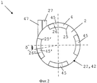
На фиг.2, где одинаковые элементы, в целом, обозначены одинаковыми ссылочными позициями, схематически, на виде сверху показан другой расходомер 1 после сборки. У расходомера 1 имеется байонетный соединитель с четырьмя парами соединительных крепежных деталей, у каждой из которых имеется крюк 45, 45' и фиксатор 26, 26' крюка (обозначенный пунктирной линией снизу крюка 45, 45'), сопрягающийся с проходом 25, 25' для крюка. В отличие от компоновки, показанной на фиг.1, крюки 45, 45', фиксаторы 26, 26' крюков и проходы 25, 25' для крюков имеют одинаковые размеры.Figure 2, where the same elements, in General, are denoted by the same reference position, schematically, in a top view shows another
Между тем, пары соединительных крепежных деталей 45, 45', 26, 26' неравномерно распределены по круговой окружности элементов 2, 4 корпуса. На фиг.2 три пары крюков 45 и фиксаторов 26 крюков последовательно расположены по окружности через угол 90°, т.е. расположены соответственно в позициях, соответствующих углам 0°, 90° и 180° по круговой окружности. Четвертая пара из крюка 45' и фиксатора 26' крюка немного смещена от подобной компоновки на угол 5, например, в диапазоне от 3 до 30°, в частности от 5 до 15°, например, около 10°. Поэтому смещенный крюк 45' и фиксатор 26' расположены по окружности в позициях, соответствующих углам 90°-δ и 90°+δ относительно соседних с ними пар соединительных крепежных деталей 45, 26. При подобном неравномерном распределении пар соединительных крепежных деталей расходомер 1 может быть установлен в одном положении, т.е. положении, при котором крюк 45' сопрягается с фиксатором 26' крюка. Соответственно выпускное отверстие 27 и впускное отверстие 47 могут быть установлены только в одном положении, как это показано на фиг.2.Meanwhile, pairs of connecting
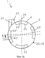
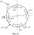
На фиг.3а и 3b, где одинаковые элементы, в целом, обозначены одинаковыми ссылочными позициями, схематически, на виде сверху показан другой расходомер 1 после сборки. В данном варианте осуществления четыре пары соединительных элементов 26, 45 неравномерно распределены вдоль круговой окружности байонетного соединителя. В данном случае четыре пары распределены таким образом, чтобы они допускали несколько различных сборочных положений, количество которых меньше количества пар соединительных крепежных деталей, например, два разных сборочных положения.On figa and 3b, where the same elements, in General, are denoted by the same reference position, schematically, in a top view shows another
На фиг.3а показано первое сборочное положение, при котором впускное отверстие 47 и выпускное отверстие 27 расположены бок о бок. На фиг.3b показано второе сборочное положение, при котором впускное отверстие 47 и выпускное отверстие 27 расположены диаметрально противоположно друг другу, с разных сторон круговой окружности расходомера 1.Fig. 3a shows a first assembly position in which the
По данному варианту осуществления расходомера 1 по изобретению две пары противолежащих крепежных элементов 26', 45' смещены на одинаковый угол δ от равномерно распределенных крепежных элементов 26, 26', 45, 45', расположенных вдоль круговой окружности расходомера 1. В данной компоновке каждый крюк 45' может сопрягаться с любым фиксатором 26' крюка. Таким образом, сборка байонетного соединителя может осуществляться в двух разных положениях.According to this embodiment, the
Аналогичный результат может быть достигнут при равномерном распределении пар соединительных крепежных элементов, состоящих из двух типов соединительных крепежных элементов, т.е. большого и малого размера. Например, узел может состоять из шести пар соединительных крепежных элементов, причем пары одного и того же типа расположены напротив друг друга с разных сторон байонетного соединителя.A similar result can be achieved with a uniform distribution of pairs of connecting fasteners, consisting of two types of connecting fasteners, i.e. large and small size. For example, a node may consist of six pairs of connecting fasteners, and pairs of the same type are located opposite each other on different sides of the bayonet connector.
Как вариант, разумеется, можно комбинировать соединительные крепежные элементы разных типов, таких как показаны на фиг.1, с неравномерным распределением пар соединительных крепежных элементов.Alternatively, of course, it is possible to combine connecting fasteners of different types, such as those shown in FIG. 1, with an uneven distribution of pairs of connecting fasteners.
Объем настоящего изобретения допускает много разных вариантов, в частности, подобные варианты позволяют использовать разные сборочные положения, под разным углом, разного размера, за счет изменения количества, расположения и типа пар соединительных крепежных элементов.The scope of the present invention allows many different options, in particular, such options allow you to use different assembly positions, at different angles, different sizes, by changing the number, location and type of pairs of connecting fasteners.
Claims (21)
- изготовлены из полиоксиметилена, например из Schulaform 9А, и из полибутилентерефталата, например из Tecdur GK30; и/или
- содержат стабилизирующий наполнитель, такой как стеклянные бусинки, причем стабилизирующий наполнитель занимает от 10 до 70% объема корпуса и/или измерительного элемента, в частности от 15 до 50% объема, например от 20 до 40% объема.18. The flow meter according to claim 17, characterized in that the housing and the measuring element:
- made of polyoxymethylene, for example from Schulaform 9A, and from polybutylene terephthalate, for example from Tecdur GK30; and / or
- contain a stabilizing filler, such as glass beads, and the stabilizing filler occupies from 10 to 70% of the volume of the housing and / or measuring element, in particular from 15 to 50% of the volume, for example from 20 to 40% of the volume.
корпус (2, 4) содержит противолежащие выступы (11), заходящие в камеру (10) и образующие точечные подшипники; и/или
поворотный вал (32) имеет ось (3′) вращения, проходящую от точечного подшипника, расположенного на первом элементе (2) корпуса (4, 2), до противолежащего точечного подшипника (11), расположенного на втором элементе (4) корпуса.20. The flow meter according to claim 19, characterized in that
the housing (2, 4) contains opposing protrusions (11), entering the chamber (10) and forming point bearings; and / or
the rotary shaft (32) has an axis of rotation (3 ′) extending from the point bearing located on the first housing element (2) (4, 2) to the opposing point bearing (11) located on the second housing element (4).
Applications Claiming Priority (3)
| Application Number | Priority Date | Filing Date | Title |
|---|---|---|---|
| EP09177590 | 2009-12-01 | ||
| EP09177590.8 | 2009-12-01 | ||
| PCT/EP2010/068272 WO2011067171A1 (en) | 2009-12-01 | 2010-11-26 | Flowmeter assembly for a beverage machine |
Publications (2)
| Publication Number | Publication Date |
|---|---|
| RU2012127369A RU2012127369A (en) | 2014-01-10 |
| RU2551393C2 true RU2551393C2 (en) | 2015-05-20 |
Family
ID=42111457
Family Applications (1)
| Application Number | Title | Priority Date | Filing Date |
|---|---|---|---|
| RU2012127369/28A RU2551393C2 (en) | 2009-12-01 | 2010-11-26 | Flow meter unit for drink preparation device |
Country Status (11)
| Country | Link |
|---|---|
| US (1) | US9101247B2 (en) |
| EP (1) | EP2507597B1 (en) |
| JP (1) | JP5768058B2 (en) |
| CN (1) | CN102639974B (en) |
| AU (1) | AU2010326841B2 (en) |
| BR (1) | BR112012013044A2 (en) |
| CA (1) | CA2782000C (en) |
| ES (1) | ES2688068T3 (en) |
| PT (1) | PT2507597T (en) |
| RU (1) | RU2551393C2 (en) |
| WO (1) | WO2011067171A1 (en) |
Families Citing this family (9)
| Publication number | Priority date | Publication date | Assignee | Title |
|---|---|---|---|---|
| US20140169013A1 (en) * | 2012-08-27 | 2014-06-19 | Tiger Accessory Group, Llc | Wireless tow light system |
| US10016550B2 (en) * | 2014-09-12 | 2018-07-10 | Easydial, Inc. | Portable hemodialysis assembly with ammonia sensor |
| US11259666B2 (en) | 2016-04-12 | 2022-03-01 | Societe Des Produits Nestle S.A. | Liquid pumping device comprising a gear pump for beverage dispenser |
| WO2018007621A1 (en) * | 2016-07-08 | 2018-01-11 | Roche Diagnostics Gmbh | Apparatus for processing a laboratory sample, laboratory automation system and method for pipetting a laboratory sample |
| CN107167203A (en) * | 2017-06-28 | 2017-09-15 | 安徽盛洲汽车部件有限公司 | Mass air flow sensor filament frame assembling structure |
| JP2019117174A (en) * | 2017-12-27 | 2019-07-18 | 株式会社A&M | Impeller type flow rate sensor and flow rate control system |
| CN112689466B (en) | 2018-09-27 | 2023-09-05 | 雀巢产品有限公司 | Self-adaptive service unit of beverage machine |
| EP3628195A1 (en) | 2018-09-27 | 2020-04-01 | Société des Produits Nestlé S.A. | Beverage preparation machine with recipient detection |
| IT202100007790A1 (en) * | 2021-03-30 | 2022-09-30 | Elbi Int Spa | DETECTION DEVICE FOR A FLOW OF LIQUID IN A DOMESTIC APPLIANCE. |
Citations (3)
| Publication number | Priority date | Publication date | Assignee | Title |
|---|---|---|---|---|
| GB2382661A (en) * | 2001-10-23 | 2003-06-04 | Dwyer Instr | Flowmeter with Hall effect sensor |
| DE102007038019A1 (en) * | 2006-08-10 | 2008-04-17 | Aquis Wasser-Luft-Systeme Gmbh, Lindau, Zweigniederlassung Rebstein | Tank for aquiferous household appliances or beverage dispensers, coffee dispensers, drinking water dispensers and/or steam cleaners, comprises a filter connector for connecting a filter cartridge in the interior of the tank |
| EP1980826A2 (en) * | 2007-04-11 | 2008-10-15 | GICAR S.r.l. | Flow meter |
Family Cites Families (11)
| Publication number | Priority date | Publication date | Assignee | Title |
|---|---|---|---|---|
| DE8408445U1 (en) | 1984-03-20 | 1985-01-03 | Plüss, Heinz, Schöndühl | MEASURING DEVICE FOR BEVERAGE LINES |
| JP2810895B2 (en) * | 1989-01-26 | 1998-10-15 | 昭俊 北野 | Compensation method for volumetric flow meter |
| GB9011036D0 (en) * | 1990-05-16 | 1990-07-04 | Veeder Root Ltd | Bayonet connector |
| FR2721381B1 (en) | 1994-06-20 | 1996-08-02 | Seb Sa | Device for producing hot water or steam. |
| DE29614076U1 (en) * | 1996-08-15 | 1997-09-11 | Digmesa Ag | Flow meter |
| EP0916381A3 (en) | 1997-11-11 | 1999-06-23 | Peter Dieckmann | Separator of products |
| JP4476287B2 (en) | 2004-06-10 | 2010-06-09 | 株式会社山武 | Flowmeter |
| CL2008002963A1 (en) | 2007-10-04 | 2010-01-22 | Nestec Sa | Heating device for a machine for the preparation of liquid food or drink, comprising a thermal unit with a metallic mass, through which the liquid circulates, and accumulates heat and supplies it to the liquid, and has one or more insured electrical components rigidly to the thermal unit; and machine. |
| EP2070454B1 (en) | 2007-12-12 | 2015-07-15 | Nestec S.A. | Beverage production machines comprising a plurality of core units |
| AU2009240123B2 (en) | 2008-04-22 | 2015-06-25 | Nestec S.A. | Modular assembly of a beverage preparation machine |
| PL2317898T3 (en) | 2008-07-14 | 2013-02-28 | Nestec Sa | Water circulation system for a beverage preparation device |
-
2010
- 2010-11-26 RU RU2012127369/28A patent/RU2551393C2/en not_active IP Right Cessation
- 2010-11-26 AU AU2010326841A patent/AU2010326841B2/en not_active Ceased
- 2010-11-26 PT PT10782306T patent/PT2507597T/en unknown
- 2010-11-26 BR BR112012013044A patent/BR112012013044A2/en not_active IP Right Cessation
- 2010-11-26 WO PCT/EP2010/068272 patent/WO2011067171A1/en active Application Filing
- 2010-11-26 ES ES10782306.4T patent/ES2688068T3/en active Active
- 2010-11-26 CA CA2782000A patent/CA2782000C/en active Active
- 2010-11-26 EP EP10782306.4A patent/EP2507597B1/en active Active
- 2010-11-26 CN CN201080053666.3A patent/CN102639974B/en active Active
- 2010-11-26 US US13/513,114 patent/US9101247B2/en active Active
- 2010-11-26 JP JP2012541418A patent/JP5768058B2/en active Active
Patent Citations (3)
| Publication number | Priority date | Publication date | Assignee | Title |
|---|---|---|---|---|
| GB2382661A (en) * | 2001-10-23 | 2003-06-04 | Dwyer Instr | Flowmeter with Hall effect sensor |
| DE102007038019A1 (en) * | 2006-08-10 | 2008-04-17 | Aquis Wasser-Luft-Systeme Gmbh, Lindau, Zweigniederlassung Rebstein | Tank for aquiferous household appliances or beverage dispensers, coffee dispensers, drinking water dispensers and/or steam cleaners, comprises a filter connector for connecting a filter cartridge in the interior of the tank |
| EP1980826A2 (en) * | 2007-04-11 | 2008-10-15 | GICAR S.r.l. | Flow meter |
Also Published As
| Publication number | Publication date |
|---|---|
| JP2013512058A (en) | 2013-04-11 |
| AU2010326841B2 (en) | 2014-12-04 |
| ES2688068T3 (en) | 2018-10-30 |
| EP2507597A1 (en) | 2012-10-10 |
| CA2782000C (en) | 2018-04-24 |
| AU2010326841A1 (en) | 2012-06-07 |
| CA2782000A1 (en) | 2011-06-09 |
| PT2507597T (en) | 2018-11-09 |
| US20120234090A1 (en) | 2012-09-20 |
| EP2507597B1 (en) | 2018-07-25 |
| CN102639974A (en) | 2012-08-15 |
| US9101247B2 (en) | 2015-08-11 |
| JP5768058B2 (en) | 2015-08-26 |
| CN102639974B (en) | 2016-05-11 |
| BR112012013044A2 (en) | 2016-11-22 |
| WO2011067171A1 (en) | 2011-06-09 |
| RU2012127369A (en) | 2014-01-10 |
Similar Documents
| Publication | Publication Date | Title |
|---|---|---|
| RU2551393C2 (en) | Flow meter unit for drink preparation device | |
| RU2571172C2 (en) | Connection of flow meter and printed circuit board in device for drinks making | |
| CA2764127C (en) | Flowmeter structure for a beverage machine | |
| CA2764125C (en) | Flowmeter materials for a beverage machine | |
| JP2013512058A5 (en) | ||
| WO2017178396A1 (en) | A liquid pumping device comprising a gear pump for beverage dispenser |
Legal Events
| Date | Code | Title | Description |
|---|---|---|---|
| PC43 | Official registration of the transfer of the exclusive right without contract for inventions |
Effective date: 20190916 |
|
| MM4A | The patent is invalid due to non-payment of fees |
Effective date: 20191127 |