RU2500951C2 - Lighting unit, display device and tv receiver - Google Patents
Lighting unit, display device and tv receiver Download PDFInfo
- Publication number
- RU2500951C2 RU2500951C2 RU2012104555/07A RU2012104555A RU2500951C2 RU 2500951 C2 RU2500951 C2 RU 2500951C2 RU 2012104555/07 A RU2012104555/07 A RU 2012104555/07A RU 2012104555 A RU2012104555 A RU 2012104555A RU 2500951 C2 RU2500951 C2 RU 2500951C2
- Authority
- RU
- Russia
- Prior art keywords
- lighting device
- mounting substrates
- light
- mounting
- substrates
- Prior art date
Links
Images


Classifications
-
- G—PHYSICS
- G02—OPTICS
- G02F—OPTICAL DEVICES OR ARRANGEMENTS FOR THE CONTROL OF LIGHT BY MODIFICATION OF THE OPTICAL PROPERTIES OF THE MEDIA OF THE ELEMENTS INVOLVED THEREIN; NON-LINEAR OPTICS; FREQUENCY-CHANGING OF LIGHT; OPTICAL LOGIC ELEMENTS; OPTICAL ANALOGUE/DIGITAL CONVERTERS
- G02F1/00—Devices or arrangements for the control of the intensity, colour, phase, polarisation or direction of light arriving from an independent light source, e.g. switching, gating or modulating; Non-linear optics
- G02F1/01—Devices or arrangements for the control of the intensity, colour, phase, polarisation or direction of light arriving from an independent light source, e.g. switching, gating or modulating; Non-linear optics for the control of the intensity, phase, polarisation or colour
- G02F1/13—Devices or arrangements for the control of the intensity, colour, phase, polarisation or direction of light arriving from an independent light source, e.g. switching, gating or modulating; Non-linear optics for the control of the intensity, phase, polarisation or colour based on liquid crystals, e.g. single liquid crystal display cells
- G02F1/133—Constructional arrangements; Operation of liquid crystal cells; Circuit arrangements
- G02F1/1333—Constructional arrangements; Manufacturing methods
- G02F1/1335—Structural association of cells with optical devices, e.g. polarisers or reflectors
- G02F1/1336—Illuminating devices
- G02F1/133602—Direct backlight
- G02F1/133611—Direct backlight including means for improving the brightness uniformity
-
- G—PHYSICS
- G02—OPTICS
- G02F—OPTICAL DEVICES OR ARRANGEMENTS FOR THE CONTROL OF LIGHT BY MODIFICATION OF THE OPTICAL PROPERTIES OF THE MEDIA OF THE ELEMENTS INVOLVED THEREIN; NON-LINEAR OPTICS; FREQUENCY-CHANGING OF LIGHT; OPTICAL LOGIC ELEMENTS; OPTICAL ANALOGUE/DIGITAL CONVERTERS
- G02F1/00—Devices or arrangements for the control of the intensity, colour, phase, polarisation or direction of light arriving from an independent light source, e.g. switching, gating or modulating; Non-linear optics
- G02F1/01—Devices or arrangements for the control of the intensity, colour, phase, polarisation or direction of light arriving from an independent light source, e.g. switching, gating or modulating; Non-linear optics for the control of the intensity, phase, polarisation or colour
- G02F1/13—Devices or arrangements for the control of the intensity, colour, phase, polarisation or direction of light arriving from an independent light source, e.g. switching, gating or modulating; Non-linear optics for the control of the intensity, phase, polarisation or colour based on liquid crystals, e.g. single liquid crystal display cells
- G02F1/133—Constructional arrangements; Operation of liquid crystal cells; Circuit arrangements
- G02F1/1333—Constructional arrangements; Manufacturing methods
- G02F1/1335—Structural association of cells with optical devices, e.g. polarisers or reflectors
- G02F1/1336—Illuminating devices
- G02F1/133602—Direct backlight
- G02F1/133603—Direct backlight with LEDs
-
- H—ELECTRICITY
- H04—ELECTRIC COMMUNICATION TECHNIQUE
- H04N—PICTORIAL COMMUNICATION, e.g. TELEVISION
- H04N5/00—Details of television systems
- H04N5/64—Constructional details of receivers, e.g. cabinets or dust covers
-
- G—PHYSICS
- G02—OPTICS
- G02F—OPTICAL DEVICES OR ARRANGEMENTS FOR THE CONTROL OF LIGHT BY MODIFICATION OF THE OPTICAL PROPERTIES OF THE MEDIA OF THE ELEMENTS INVOLVED THEREIN; NON-LINEAR OPTICS; FREQUENCY-CHANGING OF LIGHT; OPTICAL LOGIC ELEMENTS; OPTICAL ANALOGUE/DIGITAL CONVERTERS
- G02F1/00—Devices or arrangements for the control of the intensity, colour, phase, polarisation or direction of light arriving from an independent light source, e.g. switching, gating or modulating; Non-linear optics
- G02F1/01—Devices or arrangements for the control of the intensity, colour, phase, polarisation or direction of light arriving from an independent light source, e.g. switching, gating or modulating; Non-linear optics for the control of the intensity, phase, polarisation or colour
- G02F1/13—Devices or arrangements for the control of the intensity, colour, phase, polarisation or direction of light arriving from an independent light source, e.g. switching, gating or modulating; Non-linear optics for the control of the intensity, phase, polarisation or colour based on liquid crystals, e.g. single liquid crystal display cells
- G02F1/133—Constructional arrangements; Operation of liquid crystal cells; Circuit arrangements
- G02F1/1333—Constructional arrangements; Manufacturing methods
- G02F1/1335—Structural association of cells with optical devices, e.g. polarisers or reflectors
- G02F1/1336—Illuminating devices
- G02F1/133602—Direct backlight
- G02F1/133612—Electrical details
Abstract
Description
Область техникиTechnical field
[0001] Настоящее изобретение относится к осветительному устройству, устройству отображения, включающему в себя осветительное устройство, и к телевизионному приемнику, включающему в себя устройство отображения.[0001] The present invention relates to a lighting device, a display device including a lighting device, and a television receiver including a display device.
Предшествующий уровень техникиState of the art
[0002] Устройство отображения, использующее не самосветящуюся панель отображения, например, жидкокристаллическую панель отображения, обычно используется в сочетании с осветительным устройством, которое освещает панель отображения сзади. Осветительное устройство этого типа использует любой из различных типов источников света, включая трубку с холодным катодом, светоизлучающий элемент и т.п. Примеры светоизлучающего элемента включают в себя светоизлучающий диод (в дальнейшем называемый "СИД"), органический электролюминесцентный элемент, неорганический электролюминесцентный элемент и т.п., среди которых сегодня чаще всего используется СИД. Осветительное устройство, описанное в Патентном документе 1, также использует СИД в качестве источника света.[0002] A display device using a non-luminous display panel, for example, a liquid crystal display panel, is commonly used in conjunction with a lighting device that illuminates the display panel at the rear. A lighting device of this type uses any of various types of light sources, including a cold cathode tube, a light emitting element, and the like. Examples of the light emitting element include a light emitting diode (hereinafter referred to as “LED”), an organic electroluminescent element, an inorganic electroluminescent element and the like, among which LEDs are most often used today. The lighting device described in Patent Document 1 also uses LEDs as a light source.
[0003] В осветительном устройстве, описанном в Патентном документе 1, как показано на фиг. 6, СИД 122 установлен на монтажной подложке 121, и линза 124, которая покрывает СИД 122, установлен на монтажной подложке 121. Монтажная подложка 121, СИД 122 и линза 124 образуют светоизлучающий модуль mj. Множество светоизлучающих модулей mj расположены в форме матрицы, с образованием плоского источника света.[0003] In the lighting device described in Patent Document 1, as shown in FIG. 6, an
[0004] Тогда как в осветительном устройстве, описанном в Патентном документе 1, размещено множество точечных источников света, в осветительном устройстве, описанном в Патентном документе 2, размещено множество линейных источников света, например трубок с холодным катодом. В случае, когда устройство отображения используется в сочетании с осветительным устройством, в котором размещено множество источников света, как описано выше, если свет от источников света прямо входит в осветительное устройство, то возникает неравномерность в яркости на экране, и чтобы предотвратить это, рассеивающая пластина, которая рассеивает свет, расположена между источниками света и устройством отображения. Также, как и в случае с Патентным документом 2, рассеивающая пластина обычно используется в качестве составляющего компонента осветительного устройства.[0004] Whereas in the lighting device described in Patent Document 1, a plurality of point light sources are arranged, in the lighting device described in Patent Document 2 there are a plurality of linear light sources, for example cold cathode tubes. In the case where the display device is used in combination with a lighting device in which a plurality of light sources are placed, as described above, if light from the light sources directly enters the lighting device, there is an unevenness in brightness on the screen, and to prevent this, the diffusion plate that scatters light is located between the light sources and the display device. Also, as in the case of Patent Document 2, a diffuser plate is usually used as an integral component of a lighting device.
[0005] В случае, когда множество точечных источников света размещено с образованием плоского источника света, когда нужно осветить увеличенную область, может потребоваться конфигурация, в которой размещено множество монтажных подложек, каждая из которых поддерживает множество точечных источников света. Патентный документ 3 показывает один пример такой конфигурации.[0005] In the case where a plurality of point light sources are arranged to form a planar light source when an enlarged area needs to be illuminated, a configuration may be required in which a plurality of mounting substrates are placed, each of which supports a plurality of point light sources. Patent Document 3 shows one example of such a configuration.
Список цитируемых документовList of cited documents
Патентная литератураPatent Literature
[0006] Патентный документ 1: JP-A-2008-41546[0006] Patent Document 1: JP-A-2008-41546
Патентный документ 2: JP-A-2005-19065Patent Document 2: JP-A-2005-19065
Патентный документ 3: JP-A-2006-301209Patent Document 3: JP-A-2006-301209
Сущность изобретенияSUMMARY OF THE INVENTION
Техническая проблемаTechnical problem
[0007] В случае, когда множество монтажных подложек, поддерживающих точечные источники света, размещены с образованием плоского источника света, как в осветительном устройстве, описанном в Патентном документе 3, каждая пара соседних подложек среди монтажных подложек соединена друг с другом соединителем. Из-за такого соединителя может возникать неравномерность в яркости рассеивающей пластины. Нижеследующее описывает это со ссылкой на фиг. 7 и 8.[0007] In the case where a plurality of mounting substrates supporting point light sources are arranged to form a planar light source, as in the lighting device described in Patent Document 3, each pair of adjacent substrates among the mounting substrates is connected to each other by a connector. Due to such a connector, unevenness in the brightness of the scattering plate may occur. The following describes this with reference to FIG. 7 and 8.
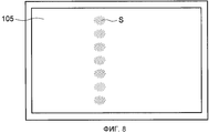
[0008] Монтажная подложка 101, показанная на фиг. 7, имеет форму прямоугольной полосы, и множество точечных источников 102 света, каждый из которых состоит из светоизлучающего элемента, установлены на монтажной подложке 101 вдоль ее продольного направления с заданным расстоянием друг от друга. В качестве монтажной подложки 101 существует тип, который поддерживает пять точечных источников 102 света, и тип, который поддерживает восемь точечных источников 102 света, и эти разные типы монтажных подложек 101 размещены последовательно и соединены друг с другом соединителем 103, и таким образом, образуют ряд 104 монтажных подложек. Множество (семь на чертеже) рядов 104 монтажных подложек размещены параллельно, с образованием плоского источника света, имеющего в целом прямоугольную форму.[0008] The
[0009] Фиг. 8 изображает рассеивающую пластину 105, освещенную вышеописанным плоским источником света. Обладая низким коэффициентом отражения, соединитель 103 виден как тень S. При позиционно выровненных соединителях 103, как показано на фиг. 7, тени S лежат на прямой линии, так что ясно воспринимается неравномерность яркости рассеивающей пластины.[0009] FIG. 8 shows a
[0010] Настоящее изобретение создано ввиду вышеизложенного и в качестве своей задачи имеет обеспечение осветительного устройства, включающего в себя рассеивающую пластину, каркас, поддерживающий рассеивающую пластину, и источник света, выполненный из множества монтажных подложек, каждая их которых поддерживает множество точечных источников света, чтобы скрыть неравномерность в яркости рассеивающей пластины, обусловленную соединителями, каждый из которых соединяет монтажные подложки.[0010] The present invention has been created in view of the foregoing, and as its task, it provides a lighting device including a diffuser plate, a frame supporting the diffuser plate, and a light source made of a plurality of mounting substrates, each of which supports a plurality of point light sources, so that hide the unevenness in the brightness of the scattering plate due to connectors, each of which connects the mounting substrate.
Решение задачиThe solution of the problem
[0011] В соответствии с предпочтительным вариантом осуществления настоящего изобретения, в осветительном устройстве, включающем в себя: рассеивающую пластину; каркас, который поддерживает рассеивающую пластину; и источник света, который расположен на каркасе и выполнен из множества монтажных подложек, поддерживающих множество точечных источников света, при этом множество монтажных подложек соединены друг с другом соединителем с образованием ряда монтажных подложек; множество рядов монтажных подложек расположены параллельно; и положения соединителей не выровнены по прямой линии в направлении, в котором размещены ряды монтажных подложек.[0011] According to a preferred embodiment of the present invention, in a lighting device including: a diffusion plate; a frame that supports the diffuser plate; and a light source that is located on the chassis and is made of a plurality of mounting substrates supporting a plurality of point light sources, wherein the plurality of mounting substrates are connected to each other by a connector to form a series of mounting substrates; many rows of mounting substrates are arranged in parallel; and the positions of the connectors are not aligned in a straight line in the direction in which the rows of mounting substrates are placed.
[0012] В соответствии с этой конфигурацией, поскольку положения соединителей не выровнены прямо, то появляющиеся из-за наличия соединителей на рассеивающей пластине тени рассредоточены, и, таким образом, скрывается неравномерность в яркости рассеивающей пластины.[0012] According to this configuration, since the positions of the connectors are not straight aligned, the shadows appearing due to the presence of the connectors on the diffuser plate are dispersed, and thus, unevenness in the brightness of the diffuser plate is hidden.
[0013] В соответствии с предпочтительным вариантом осуществления настоящего изобретения, в осветительном устройстве, имеющем вышеописанную конфигурацию, каркас имеет прямоугольную форму при виде сверху, а ряд монтажных подложек расположен параллельно продольному направлению каркаса.[0013] According to a preferred embodiment of the present invention, in the lighting device having the above configuration, the frame is rectangular in plan view, and a number of mounting substrates are parallel to the longitudinal direction of the frame.
[0014] В соответствии с предпочтительным вариантом осуществления настоящего изобретения, в осветительном устройстве, имеющем вышеописанную конфигурацию, каждая из монтажных подложек обладает формой, имеющей продольное направление, и множество монтажных подложек выровнены друг с другом вдоль продольного направления, с образованием ряда монтажных подложек.[0014] According to a preferred embodiment of the present invention, in the lighting device having the above configuration, each of the mounting substrates has a shape having a longitudinal direction, and the plurality of mounting substrates are aligned with each other along the longitudinal direction to form a series of mounting substrates.
[0015] В соответствии с этой конфигурацией с помощью множества типов монтажных подложек разной длины, другими словами, с разным количеством расположенных на них точечных источников света, подготовленных заранее, можно легко создать даже осветительное устройство отличного размера путем изменения сочетания типов монтажных подложек, которые нужно соединить друг с другом соединителем. Это устраняет необходимость проектирования монтажных подложек, предназначенных для каждого из осветительных устройств разных размеров, и, таким образом, вносит вклад в снижение стоимости.[0015] According to this configuration, using a plurality of types of mounting substrates of different lengths, in other words, with a different number of point light sources arranged thereon, prepared in advance, it is easy to create even a lighting device of a different size by changing the combination of types of mounting substrates that you need connect with each other with a connector. This eliminates the need to design mounting substrates designed for each of the lighting devices of different sizes, and thus contributes to cost reduction.
[0016] В соответствии с предпочтительным вариантом осуществления настоящего изобретения, в осветительном устройстве, имеющем вышеописанную конфигурацию, длинная монтажная подложка и короткая монтажная подложка образуют ряд монтажных подложек, и расположение длинной и короткой монтажных подложек меняется на противоположное ряд за рядом.[0016] According to a preferred embodiment of the present invention, in the lighting device having the above configuration, the long mounting substrate and the short mounting substrate form a series of mounting substrates, and the arrangement of the long and short mounting substrates is reversed row by row.
[0017] В соответствии с этой конфигурацией можно без труда спланировать так, чтобы положения соединителей не выравнивались прямо. Кроме того, эта конфигурация требует только двух типов монтажных подложек и, таким образом, не приводит к значительному увеличению стоимости.[0017] According to this configuration, it can be easily planned so that the positions of the connectors do not align directly. In addition, this configuration requires only two types of mounting substrates and, thus, does not lead to a significant increase in cost.
[0018] В соответствии с предпочтительным вариантом осуществления настоящего изобретения, в осветительном устройстве, имеющем вышеописанную конфигурацию, множество точечных источников света расположены на линии параллельно продольному направлению каждой из монтажных подложек.[0018] According to a preferred embodiment of the present invention, in a lighting device having the above configuration, a plurality of point light sources are arranged in a line parallel to the longitudinal direction of each of the mounting substrates.
[0019] В соответствии с этой конфигурацией, поскольку то, как установлены точечные источники света, однозначно определяется в зависимости от того, как установлена каждая из монтажных подложек, проектирование размещения точечных источников света упрощается.[0019] According to this configuration, since how the point light sources are installed is uniquely determined depending on how each of the mounting substrates are installed, the design of the placement of the point light sources is simplified.
[0020] В соответствии с предпочтительным вариантом осуществления настоящего изобретения, в осветительном устройстве, имеющем вышеописанную конфигурацию, множество точечных источников света расположена на линии с равным расстоянием друг от друга.[0020] According to a preferred embodiment of the present invention, in a lighting device having the above configuration, a plurality of point light sources are arranged on a line with equal distance from each other.
[0021] В соответствии с этой конфигурацией, поскольку то, как расположены точечные источники света, не меняется в зависимости от типа каждой из монтажных подложек, при этом каждая из монтажных подложек может использоваться даже в случае, когда осветительное устройство меняется по размеру.[0021] According to this configuration, since the manner in which the point light sources are arranged does not change depending on the type of each of the mounting substrates, each of the mounting substrates can be used even when the lighting device is resized.
[0022] В соответствии с предпочтительным вариантом осуществления настоящего изобретения, в осветительном устройстве, имеющем вышеописанную конфигурацию, соединитель выполнен из сочетания половин соединителя, которые установлены соответственно на одной и на другой монтажных подложках, которые нужно соединить, и по меньшей мере одна из половин соединителя выступает наружу из конечной части монтажной подложки, на которой установлена половина соединителя.[0022] According to a preferred embodiment of the present invention, in a lighting device having the above configuration, the connector is made of a combination of the connector halves that are mounted respectively on one and the other mounting substrates to be joined, and at least one of the connector halves protrudes outward from the end of the mounting substrate on which half of the connector is mounted.
[0023] В соответствии с этой конфигурацией, поскольку по меньшей мере одна из половин соединителя выступает наружу из конечной части монтажной подложки, на которой установлена половина соединителя, когда каждая пара соседних подложек среди монтажных подложек соединена соединителем, половины соединителя могут быть легко соединены друг с другом.[0023] According to this configuration, since at least one of the connector halves protrudes outward from an end portion of the mounting substrate on which half of the connector is mounted, when each pair of adjacent substrates among the mounting substrates is connected by the connector, the halves of the connector can be easily connected to each other friend.
[0024] В соответствии с предпочтительным вариантом осуществления настоящего изобретения, в осветительном устройстве, имеющем вышеописанную конфигурацию, внешняя поверхность соединителя имеет яркий цвет.[0024] According to a preferred embodiment of the present invention, in the lighting device having the above configuration, the outer surface of the connector has a bright color.
[0025] В соответствии с этой конфигурацией увеличивается отражательная способность соединителя, и, таким образом, соединитель с меньшей вероятностью поглощает свет, так что скрывается неравномерность в яркости рассеивающей пластины.[0025] According to this configuration, the reflectance of the connector is increased, and thus, the connector is less likely to absorb light, so that unevenness in the brightness of the scattering plate is hidden.
[0026] В соответствии с предпочтительным вариантом осуществления настоящего изобретения, в осветительном устройстве, имеющем вышеописанную конфигурацию, точечные источники света на монтажной подложке электрически соединены последовательно в виде одного блока.[0026] According to a preferred embodiment of the present invention, in a lighting device having the above configuration, the point light sources on the mounting substrate are electrically connected in series as a single unit.
[0027] В соответствии с этой конфигурацией ток равной величины может быть подан в каждый из точечных источников света, и, таким образом, количество света, излученного из каждого из точечных источников света, может быть выполнено равномерным, так что однородность яркости рассеивающей пластины может быть повышена.[0027] According to this configuration, equal current can be supplied to each of the point light sources, and thus, the amount of light emitted from each of the point light sources can be uniform, so that the uniformity of the brightness of the scattering plate can be promoted.
[0028] В соответствии с предпочтительным вариантом осуществления настоящего изобретения, в осветительном устройстве, имеющем вышеописанную конфигурацию, множество рядов монтажных подложек покрыты отражательным листом, и сквозные отверстия для обнажения точечных источников света и соединителей образованы сквозь отражательный лист.[0028] According to a preferred embodiment of the present invention, in a lighting device having the above configuration, a plurality of rows of mounting substrates are coated with a reflection sheet, and through holes for exposing the point light sources and connectors are formed through the reflection sheet.
[0029] В соответствии с этой конфигурацией, яркость рассеивающей пластины может быть увеличена посредством использования отражательного листа.[0029] According to this configuration, the brightness of the diffuser plate can be increased by using a reflection sheet.
[0030] В соответствии с предпочтительным вариантом осуществления настоящего изобретения, в осветительном устройстве, имеющем вышеописанную конфигурацию, каждый из точечных источников света является светоизлучающим элементом, установленным на монтажной подложке, и светоизлучающий элемент покрыт линзой.[0030] According to a preferred embodiment of the present invention, in the lighting device having the above configuration, each of the point light sources is a light emitting element mounted on a mounting substrate, and the light emitting element is coated with a lens.
[0031] В соответствии с этой конфигурацией может быть получен точечный источник света, поддающийся регулировке направленности света путем использования линзы.[0031] According to this configuration, a point light source capable of adjusting the directivity of the light by using a lens can be obtained.
[0032] В соответствии с предпочтительным вариантом осуществления настоящего изобретения, в осветительном устройстве, имеющем вышеописанную конфигурацию, линза обладает светорассеивающей функцией.[0032] In accordance with a preferred embodiment of the present invention, in a lighting device having the above configuration, the lens has a light scattering function.
[0033] В соответствии с этой конфигурации степень расхождения света, излученного из светоизлучающего элемента, становится большой, и, таким образом, можно осветить большую область с использованием относительно малого количества светоизлучающих элементов.[0033] According to this configuration, the degree of divergence of the light emitted from the light emitting element becomes large, and thus a large area can be illuminated using a relatively small number of light emitting elements.
[0034] В соответствии с предпочтительным вариантом осуществления настоящего изобретения, в осветительном устройстве, имеющем вышеописанную конфигурацию, светоизлучающим элементом является СИД.[0034] According to a preferred embodiment of the present invention, in the lighting device having the above configuration, the light emitting element is an LED.
[0035] В соответствии с этой конфигурацией можно получить осветительное устройство, который излучает свет с высокой яркостью, путем использования СИД, который в последнее время существенно улучшен в яркости. Кроме того, можно добиться большей долговечности и меньшего энергопотребления у источника света.[0035] According to this configuration, it is possible to obtain a lighting device that emits light with high brightness by using an LED, which has recently been substantially improved in brightness. In addition, you can achieve greater durability and lower power consumption at the light source.
[0036] В соответствии с предпочтительным вариантом осуществления настоящего изобретения, в осветительном устройстве, имеющем вышеописанную конфигурацию, СИД получен путем нанесения люминофора, обладающего максимумом излучения света в желтой области, на излучающий синий свет кристалл, чтобы добиться белого света.[0036] According to a preferred embodiment of the present invention, in an illumination device having the above configuration, an LED is obtained by depositing a phosphor having a maximum light emission in the yellow region on a blue light emitting crystal to achieve white light.
[0037] В соответствии с предпочтительным вариантом осуществления настоящего изобретения, в осветительном устройстве, имеющем вышеописанную конфигурацию, СИД получен путем нанесения люминофоров, обладающих максимумами излучения света в зеленой и красной областях соответственно, на излучающий синий свет кристалл, чтобы добиться белого света.[0037] According to a preferred embodiment of the present invention, in the lighting device having the above configuration, LEDs are obtained by depositing phosphors having light emitting maxima in the green and red regions, respectively, on a blue-emitting crystal to achieve white light.
[0038] В соответствии с предпочтительным вариантом осуществления настоящего изобретения, в осветительном устройстве, имеющем вышеописанную конфигурацию, СИД получен путем нанесения люминофора, обладающего максимумом излучения света в зеленой области, на излучающий синий свет кристалл, и путем использования синего светоизлучающего кристалла в сочетании с излучающим красный свет кристаллом, чтобы добиться белого света.[0038] According to a preferred embodiment of the present invention, in a lighting device having the above configuration, LEDs are obtained by depositing a phosphor having a maximum light emission in the green region onto a blue light emitting crystal, and by using a blue light emitting crystal in combination with an emitting light red light crystal to achieve white light.
[0039] В соответствии с предпочтительным вариантом осуществления настоящего изобретения, в осветительном устройстве, имеющем вышеописанную конфигурацию, СИД получен путем использования в сочетании излучающих синий, зеленый и красный свет кристаллов, соответственно, чтобы добиться белого света.[0039] According to a preferred embodiment of the present invention, in a lighting device having the above configuration, LEDs are obtained by using crystals emitting blue, green and red light, respectively, to achieve white light.
[0040] Белый светоизлучающий СИД излучает белый свет, который имеет тенденцию меняться в цветовом тоне из-за, например, высокой степени синевы. Белый свет, излученный в соответствии с настоящим изобретением, обладает сглаженным цветовым тоном, и, таким образом, можно получить свет подсветки с по существу равномерным цветовым тоном.[0040] A white light emitting LED emits white light, which tends to change in color tone due to, for example, a high degree of blue. The white light emitted in accordance with the present invention has a smoothed color tone, and thus it is possible to obtain a backlight with a substantially uniform color tone.
[0041] В соответствии с предпочтительным вариантом осуществления настоящего изобретения, в осветительном устройстве, имеющем вышеописанную конфигурацию, СИД получен с использованием кристалла ультрафиолетового свечения в сочетании с люминофором.[0041] According to a preferred embodiment of the present invention, in a lighting device having the above configuration, LEDs are obtained using an ultraviolet crystal in combination with a phosphor.
[0042] В соответствии с предпочтительным вариантом осуществления настоящего изобретения, в осветительном устройстве, имеющем вышеописанную конфигурацию, СИД получен путем нанесения люминофоров, обладающих максимумами излучения света в синей, зеленой и красной областях, соответственно, на кристалл ультрафиолетового свечения, чтобы добиться белого света.[0042] According to a preferred embodiment of the present invention, in a lighting device having the above configuration, LEDs are obtained by depositing phosphors having light emission maxima in the blue, green, and red regions, respectively, on an ultraviolet crystal to achieve white light.
[0043] В случае, когда кристалл ультрафиолетового свечение используется в качестве источника света, результирующий свет имеет тенденцию меняться в цветовом тоне. В соответствии с конфигурацией настоящего изобретения, результирующий свет обладает сглаженным цветовым тоном, и, таки образом, может быть получен свет подсветки с по существу равномерным цветовым тоном.[0043] In the case where an ultraviolet crystal is used as a light source, the resulting light tends to change in color tone. According to the configuration of the present invention, the resulting light has a smoothed color tone, and thus, backlight light with a substantially uniform color tone can be obtained.
[0044] В соответствии с предпочтительным вариантом осуществления настоящего изобретения, устройство отображения включает в себя: осветительное устройство в соответствии с любой из вышеописанных конфигураций; и панель отображения, которая получает свет от осветительного устройства.[0044] According to a preferred embodiment of the present invention, the display device includes: a lighting device in accordance with any of the above configurations; and a display panel that receives light from the lighting device.
[0045] В соответствии с этой конфигурацией может быть получено устройство отображения, обладающее скрытой неравномерностью в яркости.[0045] According to this configuration, a display device having a latent unevenness in brightness can be obtained.
[0046] В соответствии с предпочтительным вариантом осуществления настоящего изобретения, в устройстве отображения, имеющем вышеописанную конфигурацию, панель отображения является жидкокристаллической панелью.[0046] According to a preferred embodiment of the present invention, in a display device having the above configuration, the display panel is a liquid crystal panel.
[0047] В соответствии с этой конфигурацией может быть получено жидкокристаллическое устройство отображения, обладающее скрытой неравномерностью в яркости.[0047] According to this configuration, a liquid crystal display device having latent unevenness in brightness can be obtained.
[0048] В соответствии с предпочтительным вариантом осуществления настоящего изобретения, телевизионный приемник включает в себя устройство отображения, имеющее вышеописанную конфигурацию.[0048] According to a preferred embodiment of the present invention, the television receiver includes a display device having the above configuration.
[0049] В соответствии с этой конфигурацией может быть получен телевизионный приемник, обладающий скрытой неравномерностью в яркости экрана.[0049] According to this configuration, a television receiver having a hidden unevenness in screen brightness can be obtained.
Преимущественные эффекты изобретенияAdvantageous Effects of the Invention
[0050] В соответствии с настоящим изобретением в случае, когда множество монтажных подложек, поддерживающих множество точечных источников света, соединены друг с другом соединителем, с образованием ряда монтажных подложек, и множество рядов монтажных подложек расположены параллельно, с образованием плоского источник света, рассеиваются тени, образованные из-за наличия соединителей, и, таким образом, может быть получено осветительное устройство, в котором может быть скрыта неравномерность в яркости рассеивающей пластины.[0050] According to the present invention, when a plurality of mounting substrates supporting a plurality of point light sources are connected to each other by a connector to form a series of mounting substrates, and a plurality of rows of mounting substrates are arranged in parallel to form a flat light source, the shadows are scattered formed due to the presence of connectors, and thus, a lighting device can be obtained in which unevenness in the brightness of the scattering plate can be hidden.
Краткое описание чертежейBrief Description of the Drawings
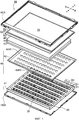
[0051] Фиг. 1 представляет собой покомпонентный вид в перспективе устройства отображения, включающего в себя осветительное устройство в соответствии с предпочтительным вариантом осуществления настоящего изобретения.[0051] FIG. 1 is an exploded perspective view of a display device including a lighting device in accordance with a preferred embodiment of the present invention.
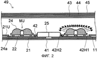
Фиг. 2 представляет собой частичный вид в поперечном сечении осветительного устройства.FIG. 2 is a partial cross-sectional view of a lighting device.
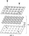
Фиг. 3 представляет собой вид сверху, изображающий расположение монтажных подложек.FIG. 3 is a plan view showing an arrangement of mounting substrates.
Фиг. 4 представляет собой вид сверху рассеивающей пластины, освещенной, в случае, когда монтажные подложки расположены как показано на фиг. 3.FIG. 4 is a plan view of a diffused plate illuminated when mounting substrates are arranged as shown in FIG. 3.
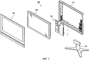
Фиг. 5 представляет собой покомпонентный вид в перспективе телевизионного приемника.FIG. 5 is an exploded perspective view of a television receiver.
Фиг. 6 представляет собой покомпонентный вид в перспективе традиционного осветительного устройства.FIG. 6 is an exploded perspective view of a conventional lighting device.
Фиг. 7 представляет собой вид сверху, изображающий пример расположения монтажных подложек.FIG. 7 is a plan view showing an example of an arrangement of mounting substrates.
Фиг. 8 представляет собой вид сверху рассеивающей пластины, освещенной, в случае, когда монтажные подложки расположены как показано на фиг. 7.FIG. 8 is a plan view of a diffused plate illuminated when mounting substrates are arranged as shown in FIG. 7.
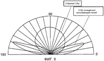
Фиг. 9 представляет собой диаграмму, изображающую, как меняется освещенность в зависимости от направления облучения СИД.FIG. 9 is a diagram illustrating how illumination changes depending on the direction of irradiation of the LEDs.
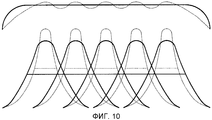
Фиг. 10 представляет собой концептуальное представление, изображающий совокупную яркость множества СИД.FIG. 10 is a conceptual representation depicting the aggregate brightness of a plurality of LEDs.
Описание вариантов осуществленияDescription of Embodiments
[0052] Ссылаясь на фиг. с 1 по 4, нижеследующее описывает конструкцию варианта осуществления устройства отображения, включающего в себя осветительное устройство в соответствии с предпочтительным вариантом осуществления настоящего изобретения. На фиг. 1 устройство 69 отображения изображено в размещенном горизонтально состоянии с его поверхностью отображения, обращенной вверх.[0052] Referring to FIG. 1 to 4, the following describes the construction of an embodiment of a display device including a lighting device in accordance with a preferred embodiment of the present invention. In FIG. 1, a
[0053] Устройство 69 отображения включает в себя жидкокристаллическую панель 59 отображения в качестве панели отображения. Жидкокристаллическая панель 59 отображения и блок 49 задней подсветки, который облучает жидкокристаллическую панель 59 отображения сзади, помещены в корпус. Корпус образован путем соединения переднего элемента HG1 корпуса и заднего элемента HG2 корпуса.[0053] The
[0054] Жидкокристаллическая панель 59 отображения образована путем прикрепления подложки 51 с активной матрицей, включающей в себя элемент переключения, например тонкопленочный транзистор (TFT) или тому подобное, к противоположной подложке 52, противоположной подложке 51 с активной матрицей, посредством непоказанного герметизирующего материала и путем наполнения жидким кристаллом пространства между подложкой 51 с активной матрицей и противоположной подложкой 52.[0054] The liquid
[0055] Поляризационная пленка 53 прикреплена к каждой из сторон светопринимающей поверхности подложки 51 с активной матрицей и стороны излучения противоположной подложки 52. Жидкокристаллическая панель 59 отображения образует изображения путем использования изменений коэффициента пропускания из-за наклона жидкокристаллических молекул.[0055] A
[0056] Блок 49 задней подсветки, воплощающий осветительное устройство в соответствии с настоящим изобретением, обладает следующей конфигурацией. А именно, блок 49 задней подсветки включает в себя светоизлучающий модуль MJ, каркас 41, крупноразмерный отражательный лист 42, рассеивающую пластину 43, лист 44 призмы и лист 45 микролинзы.[0056] The
[0057] Каркас 41 имеет прямоугольную форму при виде сверху и имеет форму лотка с восходящими стенками, образованными по внешней периферии поверхности главной плоскости, имеющей прямоугольную форму.[0057] The
[0058] Светоизлучающий модуль MJ включает в себя монтажную подложку 21, точечный источник света, расположенный на монтажной подложке 21, линзу 24, которая покрывает точечный источник света, и встроенный отражательный лист 11. Точечный источник света является светоизлучающим элементом, установленным на монтажной подложке 21. В этом варианте осуществления СИД 22 используется в качестве светоизлучающего элемента.[0058] The light emitting module MJ includes a mounting
[0059] Линза 24 обладает светорассеивающей функцией. Нижеследующее описывает значение светорассеивающей функции линзы 24. Взяв в качестве примера осветительное устройство, описанное в Патентном документе 1, в показанном на фиг. 6 осветительном устройстве, даже несмотря на то, что СИД 122 используется в сочетании с линзой 124, степень расходимости света, излученного каждым из отдельных СИД 122, является маленькой. Из-за этого, необходимо, чтобы большое количество светоизлучающих модулей mj было расположено с высокой плотностью, чтобы устранить неравномерность в яркости. Это приводит к увеличению стоимости компонентов и установки, делая устройство в целом дорогим.[0059] The
[0060] В последние годы СИД были улучшены по яркости, и, таким образом, стало возможным получение количества света, требуемого для освещения всей поверхности экрана с использованием относительно небольшого количества СИД. Однако редкое расположение СИД с высокой яркостью неминуемо вызывает неравномерность в яркости, и поэтому предпочтительно использовать каждый отдельный СИД в сочетании с линзой, обладающей светорассеивающей функцией. В этом описании изобретения линза, обладающая светорассеивающей функцией, называется "рассеивающей линзой".[0060] In recent years, LEDs have been improved in brightness, and thus it has been possible to obtain the amount of light required to illuminate the entire surface of the screen using a relatively small amount of LEDs. However, the rare arrangement of LEDs with high brightness inevitably causes unevenness in brightness, and therefore it is preferable to use each individual LED in combination with a lens having a light-scattering function. In this specification, a lens having a light scattering function is referred to as a “scattering lens".
[0061] Фиг. 9 представляет собой диаграмму, изображающую, как освещенность (единица: люкс) меняется в зависимости от направления облучения каждого из открытого СИД и СИД, оснащенного рассеивающей линзой. В случае открытого СИД освещенность достигает своего максимума при угле 90°, который является углом его оптической оси, и резко уменьшается с увеличением отклонения от угла в 90°. С другой стороны, в случае СИД, оснащенного рассеивающей линзой, значение освещенности, равное или больше, чем заданное значение, может быть обеспечено в большем диапазоне углов, и его освещенность может быть настроена так, чтобы достигать максимума при угле, отличном от угла оптической оси. Разумеется, показанное на чертеже характер освещенности может меняться различными способами в зависимости от того, как спроектирована рассеивающая линза.[0061] FIG. 9 is a diagram depicting how illumination (unit: lux) varies depending on the direction of irradiation of each of the open LEDs and LEDs equipped with a scattering lens. In the case of an open LED, illumination reaches its maximum at an angle of 90 °, which is the angle of its optical axis, and decreases sharply with an increase in the deviation from the angle of 90 °. On the other hand, in the case of an LED equipped with a scattering lens, an illumination value equal to or greater than a predetermined value can be provided in a wider range of angles, and its illumination can be adjusted so as to reach a maximum at an angle other than the angle of the optical axis . Of course, the nature of the illumination shown in the drawing can vary in various ways depending on how the scattering lens is designed.
[0062] Фиг. 10 изображает концептуальное представление совокупной яркости множества СИД. На чертеже форма волны, изображенная сплошной линией, указывает яркость СИД, оснащенного рассеивающей линзой, а форма волны, изображенная пунктирной линией, указывает яркость открытого СИД. Горизонтальная линия, нарисованная на форме волны, указывает ширину формы волны при значении яркости в половину от максимального значения (полная ширина при половине максимума). В случае СИД, каждый из которых оснащен рассеивающей линзой, можно получить каждую отдельную форму волны, имеющую увеличенную ширину, и, таким образом, форму волны у соответствующих яркостей в совокупном виде в качестве общей яркости можно легко сделать плоской, как показано сплошной линией на верхней стороне чертежа. С другой стороны, в случае открытых СИД каждая отдельная полученная форма волны является большой по высоте и малой по ширине, так что форма волны у соответствующих яркостей в совокупном виде неминуемо становится неравномерной. Изображение, имеющее такую неравномерность в яркости, является нежелательным, и, следовательно, очень важно, чтобы применялся СИД, оснащенный рассеивающей линзой.[0062] FIG. 10 is a conceptual representation of the aggregate brightness of a plurality of LEDs. In the drawing, the waveform shown by the solid line indicates the brightness of the LED equipped with the scattering lens, and the waveform shown by the dashed line indicates the brightness of the open LED. The horizontal line drawn on the waveform indicates the width of the waveform at a brightness value of half the maximum value (full width at half maximum). In the case of LEDs, each of which is equipped with a scattering lens, it is possible to obtain each individual waveform having an increased width, and thus the waveform of the respective luminances in the aggregate can easily be made flat as the total brightness, as shown by the solid line on the top side of the drawing. On the other hand, in the case of open LEDs, each individual waveform obtained is large in height and small in width, so that the waveform of the corresponding brightnesses in the aggregate form inevitably becomes uneven. An image having such unevenness in brightness is undesirable, and therefore it is very important that an LED equipped with a diffuser lens is used.
[0063] В связи с вышеизложенным, светоизлучающий модуль MJ сконфигурирован включающим в себя рассеивающую линзу 24.[0063] In connection with the foregoing, the light emitting module MJ is configured to include a
[0064] Также возможно придать рассеивающей линзе 24 светорассеивающую функцию, подвергнув поверхность рассеивающей линзы 24, обращенную к монтажной подложке 21, процессу придания шероховатости поверхности, например зернению. Это дает возможность дополнительного увеличения степени рассеяния света.[0064] It is also possible to give the
[0065] Монтажная подложка 21 имеет форму прямоугольной полосы, и на монтажной поверхности 21U, которая является верхней поверхностью монтажной подложки 21, образовано множество электродов (не показаны) на линии, параллельной продольному направлению монтажной подложки 21 на заранее установленном расстоянии друг от друга, и СИД 22 установлен на каждый из электродов. Монтажная подложка 21 используется в качестве общей подложки, совместно используемой множеством СИД 22. То есть, как показано на фиг. 1 и 3, множество светоизлучающих модулей MJ, каждый из которых включает СИД 22 и рассеивающую линзу 24, расположены на линии параллельной продольному направлению монтажной подложки 21 на заранее установленном расстоянии друг от друга, в этом случае на заранее установленном равном расстоянии друг от друга. Монтажная подложка 21 прикреплена к каркасу 41 подходящим образом путем, например, штампования, привязывания, привинчивания или приклепывания к нему.[0065] The mounting
[0066] Поскольку множество СИД 22 расположены на монтажной подложке 21, которая имеет форму, обладающую продольным направлением, и монтажная подложка 21 в том состоянии установлена на каркас 41, эффективность работы может быть повышена по сравнению со случаем, когда СИД 22 установлены на каркас 41 один за другим. Кроме того, поскольку множество СИД 22 расположены на линии параллельной продольному направлению монтажной подложки 21, то, как установлены СИД 22, определяется однозначно в зависимости от того, как установлена монтажная подложка 21, и, таким образом, упрощается проектирование расположения СИД 22. Поскольку множество СИД 22 расположены на линии на равном расстоянии друг от друга, то, как расположены СИД 22, не меняется в зависимости от типа монтажной подложки 21, и, таким образом, монтажная подложка 21 может быть использована даже в случае, когда блок 49 задней подсветки изменен по размеру.[0066] Since a plurality of
[0067] Встроенный отражательный лист 11 расположен между монтажной подложкой 21 и рассеивающей линзой 24. Встроенный отражательный лист 11 закреплен в положении на монтажной поверхности 21U, в котором монтажная поверхность 21U обращена к нижней поверхности рассеивающей линзы 24. Встроенный отражательный лист 11 обладает коэффициентом отражения выше, чем коэффициент отражения монтажной подложки 21. Встроенный отражательный лист 11 также имеет круглую форму при виде сверху, и является концентрическим с рассеивающей линзой 24. Диаметр встроенного отражательного листа 11 больше, чем диаметр рассеивающей линзы 24.[0067] An
[0068] Встроенный отражательный лист 11 является листом вспененной смолы, содержащей множество мелких воздушных пузырьков внутри, и отражает свет путем активного использования граничного отражения воздушных пузырьков, таким образом, обладая высокой коэффициентом отражения. Желательно выбрать существующий лист, который изготовлен из полиэтилентерефталата (PET) и обладает коэффициентом отражения 98% или выше. Сквозное отверстие для прохождения каждой из ножек 24a рассеивающей линзы 24 через него образовано сквозь встроенный отражательный лист 11.[0068] The
[0069] Рассеивающая линза 24 имеет круглую форму при виде сверху и снабжена множеством ножек 24a на ее нижней поверхности. Каждая из ножек 24a проходит через сквозное отверстие встроенного отражательного листа 11 и затем присоединяется своим концом к монтажной поверхности 21U монтажной подложки 21 с использованием клея, и, таким образом, рассеивающая линза 24 установлена на монтажную подложку 21. Наличие ножек 24a обеспечивает зазор между монтажной подложкой 21 и рассеивающей линзой 24. Воздушный поток через этот зазор охлаждает СИД 22. При условии, что проблема теплового излучения может быть решена, также можно использовать светоизлучающий модуль цельноформованного типа, полученный путем встраивания СИД в рассеивающую линзу.[0069] The
[0070] В качестве СИД 22 могут быть использованы различные типы СИД. Например, могут быть использованы СИД типа, полученного путем нанесения люминофора, обладающего максимумом излучения света в желтой области, на излучающий синий свет кристалл, чтобы добиться белого света. Также может использоваться СИД типа, полученного путем нанесения люминофоров, обладающих максимумами излучения света в зеленой и красной областях соответственно, на излучающий синий свет кристалл, чтобы добиться белого света. Кроме того, может использоваться СИД типа, полученного путем нанесения люминофора, обладающего максимумом излучения света в зеленой области, на излучающий синий свет кристалл и путем использования синего светоизлучающего кристалла в сочетании с излучающим красный свет кристаллом, чтобы добиться белого света. К тому же может использоваться СИД типа, использующего в сочетании излучающие синий, зеленый и красный свет кристаллы соответственно, чтобы добиться белого света.[0070] As the
[0071] Белый светоизлучающий СИД излучает белый свет, который имеет тенденцию меняться в цветовом тоне, например, из-за высокой степени синевы. Белый свет, излученный любым из вышеописанных способов, обладает сглаженным цветовым тоном, и, таким образом, может быть получен свет подсветки практически с равномерным цветовым тоном.[0071] The white light emitting LED emits white light, which tends to change in color tone, for example, due to a high degree of blue. The white light emitted by any of the above methods has a smoothed color tone, and thus, the illumination light with an almost uniform color tone can be obtained.
[0072] Другие типы СИД, которые также могут быть использованы, включают в себя тип, использующий кристалл ультрафиолетового свечения в сочетании с люминофором, в частности тип, полученный путем нанесения люминофоров, обладающих максимумами излучения света в синей, зеленой и красной областях соответственно, на кристалл ультрафиолетового свечения, чтобы добиться белого света.[0072] Other types of LEDs that may also be used include a type using an ultraviolet crystal in combination with a phosphor, in particular a type obtained by applying phosphors having maximum light emission in the blue, green, and red regions, respectively, on crystal ultraviolet light to achieve white light.
[0073] В случае, когда кристалл ультрафиолетового свечения используется в качестве источника света, результирующий свет имеет тенденцию меняться в цветовом тоне. С другой стороны, с помощью вышеописанной конфигурации результирующий свет обладает сглаженным цветовым тоном, и, таким образом, может быть получен свет подсветки с по существу равномерным цветовым тоном.[0073] In the case where an ultraviolet crystal is used as a light source, the resulting light tends to change in color tone. On the other hand, with the above configuration, the resulting light has a smoothed color tone, and thus, backlight with a substantially uniform color tone can be obtained.
[0074] Существует два типа монтажной подложки 21: один тип имеет восемь размещенных на нем светоизлучающих модулей MJ, а другой имеет пять размещенных на нем светоизлучающих модулей MJ. Когда выполняется сравнение, то естественно первый имеет длину больше, чем последний. Две монтажные подложки 21 этих длинного и короткого типов размещены так, чтобы быть выровненными друг с другом вдоль продольного направления, и соединены друг с другом соединителем 25, таким образом, образуя ряд 26 монтажных подложек. На каждой из монтажных подложек 21 точка соединения, определенная соединителем 25, отстоит от одного из соседних с ней светоизлучающих модулей MJ на расстояние, равное расстоянию между каждой парой соседних светоизлучающих модулей MJ.[0074] There are two types of mounting substrate 21: one type has eight light emitting MJ modules disposed thereon, and the other has five light emitting MJ modules disposed thereon. When the comparison is performed, then naturally the first has a length greater than the last. Two mounting
[0075] Соединитель 25 изготовлен из вилочной половины соединителя и розеточной половины соединителя, которые установлены соответственно на противоположных конечных частях двух монтажных подложек 21, при этом одна из двух монтажных подложек 21 имеет пять светоизлучающих модулей MJ, а другая - восемь. По меньшей мере одна из половин соединителя выступает за пределы конечной части монтажной подложки 21, на которую установлена упомянутая половина соединителя. Таким образом, половины соединителя могут быть без труда соединены друг с другом. В варианте осуществления, показанном на фиг. 1, обе половины соединителя выступают наружу из соответствующих конечных частей монтажных подложек 21, на которые соответственно установлены половины соединителя.[0075] The
[0076] В итоге семь рядов 26 монтажных подложек расположены параллельно, так чтобы каждый из них был параллелен продольному направлению каркаса 41. На монтажной подложке 21 светоизлучающие модули MJ размещены в направлении длинной стороны каркаса 41, а именно в направлении, указанном стрелкой X на фиг. 1, а ряды 26 монтажных подложек размещены в направлении короткой стороны каркаса 41, а именно в направлении, указанном стрелкой Y на фиг. 1. Таким образом, светоизлучающие модули MJ и соединители 25 размещены в форме матрицы. В каждом из семи рядов 26 монтажных подложек две монтажные подложки 21 соответствующего длинного и короткого типов расположены так, чтобы их положения менялись на противоположные ряд за рядом. Таким образом, в направлении, в котором размещены ряды 26 монтажных подложек, а именно в направлении стрелки Y, положения соединителей 25 не выровнены по прямой линии, а находятся в зигзагообразном размещении.[0076] As a result, seven
[0077] Отражательный лист 42, имеющий аналогичную форму при виде сверху на каркас 41, уложен на каркас 41. В качестве отражательного листа 42 используется лист вспененной смолы типа, аналогичного типу, используемому для встроенного отражательного листа 11. Круглое сквозное отверстие 42H1, имеющее размер, достаточный для прохождения через него рассеивающей линзы 24, но недостаточный для прохождения встроенного отражательного листа 11, образовано в отражательном листе 24, соответствующим положению каждого из светоизлучающих модулей MJ, и, таким образом, каждый из светоизлучающих модулей MJ обнажается через сквозное отверстие 42H1. Кроме того, прямоугольное сквозное отверстие 42H2 для обнажения соединителя 25 также образовано в отражательном листе 42, соответствующим положению каждого из соединителей 25.[0077] A
[0078] Когда зажигается СИД 22 светоизлучающего модуля MJ, рассеивающая пластина 43 облучается сзади светом, излученным из СИД 22. Часть света, который не движется непосредственно в направлении рассеивающей пластины 43, отражается встроенным отражательным листом 11 и отражательным листом 42 к рассеивающей пластине 43. Свет рассеивается внутри рассеивающей пластины 43, так что снаружи рассеивающая пластина 43 видна как плоскость с относительно равномерной яркостью.[0078] When the
[0079] СИД 22 на паре монтажных подложек 21, соединенных соединителем 25, или все СИД 22 могут быть электрически соединены последовательно. При этой конфигурации ток равной величины может подаваться в каждый из СИД 22, и, таким образом, можно сделать равномерным количество света, излученного из каждого из СИД 22, так что однородность яркости рассеивающей пластины 43 может быть повышена.[0079] The
[0080] Как показано на фиг. 4, за счет наличия соединителей 25, обнаженных из отражательного листа 42, тени S появляются на поверхности яркости рассеивающей пластины 43. Поскольку положения соединителей 25 не выровнены по прямой линии, тени S рассредоточены. Таким образом, скрывается неравномерность в яркости рассеивающей пластины 43.[0080] As shown in FIG. 4, due to the presence of
[0081] Если соединители 25 обладают высоким коэффициентом отражения, то тени S скрываются. С этой целью соединитель 25 сконфигурирован так, чтобы его внешняя поверхность, а именно его часть, которая обнажается наружу, когда соединитель 25 соединяется с монтажными подложками 21, имела яркий цвет. В частности, оболочка соединителя 25 образована с использованием выбранного материала или красится, чтоб иметь яркий цвет, например белый, цвет слоновой кости или светло-серый. Это увеличивает коэффициент отражения соединителя 25, и, таким образом, соединитель 25 с меньшей вероятностью поглощает свет, так что скрывается неравномерность в яркости рассеивающей пластины 43.[0081] If the
[0082] Расположение монтажных подложек вышеупомянутого варианта осуществления не должно толковаться как ограничивающее объект изобретения. Количество рядов 26 монтажных подложек, количество светоизлучающих модулей MJ, которое нужно поддерживать одной монтажной подложкой 21, матричная структура светоизлучающих модулей MJ и так далее может задаваться свободно. Кроме того, хотя в вышеупомянутом варианте осуществления в каждом из рядов 26 монтажных подложек длинная монтажная подложка 21 и короткая монтажная подложка 21 расположены так, что их положения меняются на противоположные ряд за рядом, также существуют другие способы, с помощью которых ряды 26 монтажных подложек могут быть размещены в смешанном состоянии, где положения длинной монтажной подложки 21 и короткой монтажной подложки 21 в одном ряду меняются на противоположные в другом ряду. Например, может применяться способ, в котором в каждом из первых двух рядов 26 монтажных подложек монтажная подложка 21 длинного типа расположена по левой стороне, а монтажная подложка 21 короткого типа расположена по правой стороне, тогда как в каждом из вторых двух рядов 26 монтажных подложек монтажная подложка 21 короткого типа расположена по левой стороне, а монтажная подложка 21 длинного типа расположена по правой стороне, и для оставшихся рядов эта перестановка происходит многократно.[0082] The arrangement of mounting substrates of the above embodiment should not be construed as limiting the subject matter of the invention. The number of
[0083] Фиг. 5 изображает пример конфигурации телевизионного приемника, в который встроено устройство 69 отображения. Телевизионный приемник 89 обладает конфигурацией, в которой в корпусе, образованном путем соединения передней части 90 корпуса и задней части 91 корпуса вместе, размещены устройство 69 отображения и группа 92 плат управления, и корпус поддерживается подставкой 93.[0083] FIG. 5 shows an example configuration of a television receiver in which a
[0084] Выше был рассмотрен вариант осуществления настоящего изобретения. Однако настоящее изобретение не ограничивается описанным объемом и может быть осуществлено в различно измененных формах без отклонения от сущности изобретения.[0084] An embodiment of the present invention has been discussed above. However, the present invention is not limited to the described volume and can be implemented in variously modified forms without deviating from the essence of the invention.
Промышленная применимостьIndustrial applicability
[0085] Настоящее изобретение может широко применяться к осветительному устройству, в котором рассеивающая пластина облучается светом от источника света. Кроме того, настоящее изобретение может широко применяться также к устройству отображения, включающему в себя упомянутое осветительное устройство, и, кроме того, к телевизионному приемнику, включающему в себя упомянутое устройство отображения.[0085] The present invention can be widely applied to a lighting device in which a diffuser plate is irradiated with light from a light source. In addition, the present invention can also be widely applied to a display device including said lighting device, and, in addition, to a television receiver including said display device.
Список ссылочных позицийList of Reference Items
[0086] 49 блок задней подсветки[0086] 49 backlight unit
41 каркас41 frame
43 рассеивающая пластина43 diffuser plate
MJ светоизлучающий модульMJ light emitting module
21 монтажная подложка21 mounting pad
22 СИД22 LEDs
24 рассеивающая линза24 diffuser lens
11 встроенный отражательный лист11 integrated reflective sheet
25 соединитель25 connector
42 отражательный лист42 reflection sheet
42H1, 41H2 сквозное отверстие42H1, 41H2 through hole
59 жидкокристаллическая панель отображения59 liquid crystal display panel
69 устройство отображения69 display device
89 телевизионный приемник89 television receiver
Claims (23)
рассеивающую пластину;
каркас, который поддерживает рассеивающую пластину; и
источник света, который расположен на каркасе и выполнен из множества монтажных подложек, каждая из которых поддерживает множество точечных источников света,
при этом множество монтажных подложек соединены друг с другом соединителем с образованием ряда монтажных подложек,
множество рядов монтажных подложек расположены параллельно, при этом
ряд монтажных площадок образован длинной монтажной подложкой и короткой монтажной подложкой, и
расположение длинной и короткой монтажных подложек меняется на противоположное ряд за рядом, и положения соединителей не выровнены по прямой линии в направлении, в котором размещены ряды монтажных подложек.1. A lighting device comprising:
diffusion plate;
a frame that supports the diffuser plate; and
a light source that is located on the frame and is made of many mounting substrates, each of which supports many point light sources,
however, many mounting substrates are connected to each other by a connector with the formation of a number of mounting substrates,
many rows of mounting substrates are arranged in parallel, while
a number of mounting sites are formed by a long mounting substrate and a short mounting substrate, and
the arrangement of the long and short mounting substrates changes to the opposite row after row, and the positions of the connectors are not aligned in a straight line in the direction in which the rows of mounting substrates are placed.
каркас имеет прямоугольную форму при виде сверху, и
ряд монтажных подложек расположен параллельно продольному направлению каркаса.2. The lighting device according to claim 1, in which
the frame is rectangular in plan view, and
a number of mounting substrates are parallel to the longitudinal direction of the frame.
каждая из монтажных подложек имеет форму, обладающую продольным направлением, и
множество монтажных подложек выровнены друг с другом вдоль продольного направления с образованием ряда монтажных подложек.3. The lighting device according to claim 1, wherein
each of the mounting substrates has a shape having a longitudinal direction, and
a plurality of mounting substrates are aligned with each other along a longitudinal direction to form a series of mounting substrates.
рассеивающую пластину,
каркас, который поддерживает рассеивающую пластину, и
источник света, который расположен на каркасе и выполнен из множества монтажных подложек, каждая из которых поддерживает множество точечных источников света,
при этом множество монтажных подложек соединены друг с другом соединителем с образованием ряда монтажных подложек,
множество рядов монтажных подложек расположены параллельно,
положения соединителей не выровнены по прямой линии в направлении, в котором размещены ряды монтажных подложек,
каждая из монтажных подложек имеет форму, обладающую продольным направлением, и
множество монтажных площадок выровнены друг с другом вдоль продольного направления с образованием указанного ряда монтажных подложек,
указанный ряд монтажных подложек образован длинной монтажной подложкой и короткой монтажной подложкой, и
расположение длинной и короткой монтажных подложек меняется на противоположное ряд за рядом.4. A lighting device comprising:
diffusion plate
a frame that supports the diffuser plate, and
a light source that is located on the frame and is made of many mounting substrates, each of which supports many point light sources,
however, many mounting substrates are connected to each other by a connector with the formation of a number of mounting substrates,
many rows of mounting substrates are arranged in parallel,
the position of the connectors is not aligned in a straight line in the direction in which the rows of mounting substrates are placed,
each of the mounting substrates has a shape having a longitudinal direction, and
many mounting sites are aligned with each other along the longitudinal direction with the formation of the specified number of mounting substrates,
said row of mounting substrates is formed by a long mounting substrate and a short mounting substrate, and
the location of the long and short mounting substrates is reversed row by row.
множество точечных источников света расположены в линию, параллельную продольному направлению каждой из монтажных подложек.5. The lighting device according to claim 3, in which
a plurality of point light sources are arranged in a line parallel to the longitudinal direction of each of the mounting substrates.
множество точечных источников света расположены в линию на равном расстоянии друг от друга.6. The lighting device according to claim 5, wherein
many point light sources are arranged in a line at an equal distance from each other.
соединитель выполнен из сочетания половин соединителя, которые установлены соединяемыми соответственно на одной и на другой монтажных подложках, и,
по меньшей мере, одна из половин соединителя выступает наружу из конечной части монтажной подложки, на которую установлена упомянутая половина соединителя.7. The lighting device according to claim 1, wherein
the connector is made from a combination of connector halves that are mounted to be connected respectively to one and the other mounting substrates, and,
at least one of the connector halves protrudes outward from the end portion of the mounting substrate on which said connector half is mounted.
внешняя поверхность соединителя имеет яркий цвет.8. The lighting device according to claim 1, wherein
the outer surface of the connector has a bright color.
точечные источники света на монтажной подложке электрически соединены последовательно в виде одного блока.9. The lighting device according to claim 1, wherein
point light sources on a mounting substrate are electrically connected in series as a single unit.
множество рядов монтажных подложек покрыты отражательным листом, и
сквозь отражательный лист образованы сквозные отверстия для обнажения точечных источников света и соединителей.10. The lighting device according to claim 1, in which
a plurality of rows of mounting substrates are coated with a reflection sheet, and
through the reflection sheet, through holes are formed to expose the point light sources and connectors.
каждый из точечных источников света является светоизлучающим элементом, установленным на монтажной подложке, и
светоизлучающий элемент покрыт линзой.11. The lighting device according to claim 1, in which
each of the point light sources is a light emitting element mounted on a mounting substrate, and
the light emitting element is coated with a lens.
линза обладает светорассеивающей функцией.12. The lighting device according to claim 11, in which
the lens has a light scattering function.
светоизлучающим элементом является СИД.14. The lighting device according to claim 11, in which
the light emitting element is an LED.
СИД получен путем нанесения люминофора, обладающего максимумом излучения света в желтой области, на излучающий синий свет кристалл, чтобы получить белый свет.15. The lighting device according to 14, in which
An LED is obtained by applying a phosphor having a maximum light emission in the yellow region to a blue-emitting crystal to obtain white light.
СИД получен путем нанесения люминофоров, обладающих максимумами излучения света в зеленой и красной областях соответственно, на излучающий синий свет кристалл, чтобы получить белый свет.16. The lighting device according to 14, in which
An LED is obtained by applying phosphors having light emission maxima in the green and red regions, respectively, to a crystal emitting blue light to obtain white light.
СИД получен путем нанесения люминофора, обладающего максимумом излучения света в зеленой области, на излучающий синий свет кристалл и путем использования излучающего синий свет кристалла в сочетании с излучающим красный свет кристаллом, чтобы получить белый свет.17. The lighting device according to 14, in which
An LED is obtained by applying a phosphor having a maximum light emission in the green region to a blue light emitting crystal and using a blue light emitting crystal in combination with a red light emitting crystal to obtain white light.
СИД получен путем использования в сочетании излучающих синий, зеленый и красный свет кристаллов соответственно, чтобы получить белый свет.18. The lighting device according to 14, in which
LEDs are obtained by using crystals emitting blue, green, and red light in combination, respectively, to obtain white light.
СИД получен путем использования кристалла ультрафиолетового свечения в сочетании с люминофором.19. The lighting device according to 14, in which
LED obtained by using a crystal of ultraviolet light in combination with a phosphor.
СИД получен путем нанесения люминофоров, обладающих максимумами излучения света в синей, зеленой и красной областях соответственно, на кристалл ультрафиолетового свечения, чтобы получить белый свет.20. The lighting device according to claim 19, wherein
An LED is obtained by applying phosphors having light emission maxima in the blue, green, and red regions, respectively, to an ultraviolet crystal in order to obtain white light.
осветительное устройство по любому из пп.1-20; и
панель отображения, которая получает свет от осветительного устройства.21. A display device comprising:
a lighting device according to any one of claims 1 to 20; and
a display panel that receives light from a lighting device.
панель отображения является жидкокристаллической панелью отображения.22. The display device according to item 21, while
the display panel is a liquid crystal display panel.
Applications Claiming Priority (3)
| Application Number | Priority Date | Filing Date | Title |
|---|---|---|---|
| JP2009162447 | 2009-07-09 | ||
| JP2009-162447 | 2009-07-09 | ||
| PCT/JP2010/052310 WO2011004623A1 (en) | 2009-07-09 | 2010-02-17 | Illumination device, display device, and television receiver |
Publications (2)
| Publication Number | Publication Date |
|---|---|
| RU2012104555A RU2012104555A (en) | 2013-08-27 |
| RU2500951C2 true RU2500951C2 (en) | 2013-12-10 |
Family
ID=43429048
Family Applications (1)
| Application Number | Title | Priority Date | Filing Date |
|---|---|---|---|
| RU2012104555/07A RU2500951C2 (en) | 2009-07-09 | 2010-02-17 | Lighting unit, display device and tv receiver |
Country Status (7)
| Country | Link |
|---|---|
| US (1) | US8482679B2 (en) |
| EP (1) | EP2453161A4 (en) |
| JP (1) | JP5138814B2 (en) |
| CN (1) | CN102472438B (en) |
| BR (1) | BR112012000532A2 (en) |
| RU (1) | RU2500951C2 (en) |
| WO (1) | WO2011004623A1 (en) |
Families Citing this family (8)
| Publication number | Priority date | Publication date | Assignee | Title |
|---|---|---|---|---|
| CN103244871B (en) * | 2013-04-28 | 2015-07-01 | 京东方科技集团股份有限公司 | Direct type backlight module and liquid crystal display device |
| CN103423675B (en) * | 2013-09-09 | 2016-05-25 | 广州创维平面显示科技有限公司 | A kind of down straight aphototropism mode set and liquid crystal display |
| DE102014104336A1 (en) * | 2014-03-27 | 2015-10-01 | Osram Gmbh | LED luminaire with refractive optics for light mixing |
| CN107250659B (en) * | 2015-02-25 | 2019-07-16 | 夏普株式会社 | Lighting device, display device and radiovisor |
| CN105546362B (en) * | 2016-01-27 | 2020-11-17 | 江西依瓦塔光电科技有限公司 | LED optical system for forming uniform square light spots |
| DE202017100470U1 (en) * | 2017-01-30 | 2018-05-03 | Zumtobel Lighting Gmbh | Luminaire and (pre-) optics for luminaire |
| KR20230018224A (en) * | 2021-07-29 | 2023-02-07 | 삼성전자주식회사 | Display apparatus |
| EP4283385A1 (en) | 2021-07-29 | 2023-11-29 | Samsung Electronics Co., Ltd. | Display device |
Citations (5)
| Publication number | Priority date | Publication date | Assignee | Title |
|---|---|---|---|---|
| RU2234120C2 (en) * | 1999-07-06 | 2004-08-10 | Интернэшнл Бизнес Машинз Корпорейшн | Portable computer with keyboard illumination |
| JP2005019065A (en) * | 2003-06-24 | 2005-01-20 | Advanced Display Inc | Backlight device and image display unit |
| WO2008007492A1 (en) * | 2006-07-11 | 2008-01-17 | Koha Co., Ltd. | Light source module, surface area light-emitting unit, and surface area light-emitting device |
| JP2008041546A (en) * | 2006-08-09 | 2008-02-21 | Showa Denko Kk | Light-emitting device, display device and cover attaching member |
| JP2008147147A (en) * | 2006-12-13 | 2008-06-26 | Sony Corp | Backlight device and liquid crystal display device |
Family Cites Families (14)
| Publication number | Priority date | Publication date | Assignee | Title |
|---|---|---|---|---|
| JP4701806B2 (en) | 2005-04-19 | 2011-06-15 | ソニー株式会社 | Backlight device and liquid crystal display device |
| JP4467491B2 (en) * | 2005-09-06 | 2010-05-26 | シャープ株式会社 | Backlight device, liquid crystal display device |
| US8021033B2 (en) * | 2005-11-30 | 2011-09-20 | Showa Denko K.K. | Light guide member, planar light source device provided with the light guide member, and display apparatus using the planar light source device |
| JP2007157698A (en) * | 2005-12-06 | 2007-06-21 | Samsung Electronics Co Ltd | Lamp fixing member, and backlight assembly having it, and liquid crystal display device |
| JP4577229B2 (en) * | 2006-02-16 | 2010-11-10 | 日本電気株式会社 | Backlight device and liquid crystal display device |
| US20080049164A1 (en) * | 2006-08-22 | 2008-02-28 | Samsung Electronics Co., Ltd., | Backlight assembly, manufacturing method thereof, and liquid crystal display device |
| US8514165B2 (en) * | 2006-12-28 | 2013-08-20 | Semiconductor Energy Laboratory Co., Ltd. | Semiconductor device |
| JP2008304500A (en) * | 2007-06-05 | 2008-12-18 | Asahi Kasei Chemicals Corp | Diffusion plate |
| JP5213383B2 (en) * | 2007-08-09 | 2013-06-19 | シャープ株式会社 | LIGHT EMITTING DEVICE AND LIGHTING DEVICE EQUIPPED WITH THE SAME |
| JP4290753B2 (en) * | 2007-08-10 | 2009-07-08 | シャープ株式会社 | LED light source, LED light source manufacturing method, surface light source device, and video display device |
| JP2009076456A (en) * | 2007-08-31 | 2009-04-09 | Sharp Corp | Backlight device and display device |
| CN101842632A (en) * | 2007-11-07 | 2010-09-22 | 夏普株式会社 | Illuminating device and image display device |
| JP2009140835A (en) * | 2007-12-08 | 2009-06-25 | Citizen Electronics Co Ltd | Light emitting device, plane light unit, and display device |
| KR101441309B1 (en) * | 2008-01-28 | 2014-09-17 | 삼성디스플레이 주식회사 | Display system |
-
2010
- 2010-02-17 US US13/379,106 patent/US8482679B2/en active Active
- 2010-02-17 RU RU2012104555/07A patent/RU2500951C2/en not_active IP Right Cessation
- 2010-02-17 CN CN201080027161.XA patent/CN102472438B/en active Active
- 2010-02-17 JP JP2011521838A patent/JP5138814B2/en not_active Expired - Fee Related
- 2010-02-17 EP EP10796934.7A patent/EP2453161A4/en not_active Withdrawn
- 2010-02-17 WO PCT/JP2010/052310 patent/WO2011004623A1/en active Application Filing
- 2010-02-17 BR BR112012000532A patent/BR112012000532A2/en not_active IP Right Cessation
Patent Citations (5)
| Publication number | Priority date | Publication date | Assignee | Title |
|---|---|---|---|---|
| RU2234120C2 (en) * | 1999-07-06 | 2004-08-10 | Интернэшнл Бизнес Машинз Корпорейшн | Portable computer with keyboard illumination |
| JP2005019065A (en) * | 2003-06-24 | 2005-01-20 | Advanced Display Inc | Backlight device and image display unit |
| WO2008007492A1 (en) * | 2006-07-11 | 2008-01-17 | Koha Co., Ltd. | Light source module, surface area light-emitting unit, and surface area light-emitting device |
| JP2008041546A (en) * | 2006-08-09 | 2008-02-21 | Showa Denko Kk | Light-emitting device, display device and cover attaching member |
| JP2008147147A (en) * | 2006-12-13 | 2008-06-26 | Sony Corp | Backlight device and liquid crystal display device |
Also Published As
| Publication number | Publication date |
|---|---|
| EP2453161A4 (en) | 2013-11-13 |
| EP2453161A1 (en) | 2012-05-16 |
| RU2012104555A (en) | 2013-08-27 |
| BR112012000532A2 (en) | 2019-09-24 |
| CN102472438A (en) | 2012-05-23 |
| CN102472438B (en) | 2014-06-25 |
| WO2011004623A1 (en) | 2011-01-13 |
| US8482679B2 (en) | 2013-07-09 |
| US20120099027A1 (en) | 2012-04-26 |
| JPWO2011004623A1 (en) | 2012-12-20 |
| JP5138814B2 (en) | 2013-02-06 |
Similar Documents
| Publication | Publication Date | Title |
|---|---|---|
| RU2503881C2 (en) | Backlight device, display device and television receiver | |
| RU2496050C2 (en) | Lighting device, display device and television receiver | |
| RU2500951C2 (en) | Lighting unit, display device and tv receiver | |
| US8827478B2 (en) | Lighting device, display device, and television receiver | |
| RU2503882C2 (en) | Backlight device, display device and television receiver | |
| US8251529B2 (en) | Thin illumination device, display device and luminary device | |
| US8579456B2 (en) | Backlight unit | |
| WO2010146894A1 (en) | Light emitting module, illuminating device, display device, and television receiver | |
| RU2430299C2 (en) | Intensifier, display and tv receiver | |
| RU2430298C2 (en) | Intensifier, display and tv receiver | |
| RU2499183C2 (en) | Backlighting device, display device and tv set | |
| EP2428719B1 (en) | Illumination device, display device, and television receiver | |
| JP5713416B2 (en) | Lighting device, ceiling light, backlight, liquid crystal display device, and television receiver | |
| KR20060021141A (en) | Back-light assembly and display having the same | |
| KR200424281Y1 (en) | Backlight unit using LED as lightsource |
Legal Events
| Date | Code | Title | Description |
|---|---|---|---|
| MM4A | The patent is invalid due to non-payment of fees |
Effective date: 20190218 |