RU2496060C2 - Heating element - Google Patents
Heating element Download PDFInfo
- Publication number
- RU2496060C2 RU2496060C2 RU2009127811/12A RU2009127811A RU2496060C2 RU 2496060 C2 RU2496060 C2 RU 2496060C2 RU 2009127811/12 A RU2009127811/12 A RU 2009127811/12A RU 2009127811 A RU2009127811 A RU 2009127811A RU 2496060 C2 RU2496060 C2 RU 2496060C2
- Authority
- RU
- Russia
- Prior art keywords
- elements
- element according
- resistances
- rows
- heating
- Prior art date
Links
Images


Classifications
-
- F—MECHANICAL ENGINEERING; LIGHTING; HEATING; WEAPONS; BLASTING
- F24—HEATING; RANGES; VENTILATING
- F24D—DOMESTIC- OR SPACE-HEATING SYSTEMS, e.g. CENTRAL HEATING SYSTEMS; DOMESTIC HOT-WATER SUPPLY SYSTEMS; ELEMENTS OR COMPONENTS THEREFOR
- F24D13/00—Electric heating systems
- F24D13/02—Electric heating systems solely using resistance heating, e.g. underfloor heating
-
- Y—GENERAL TAGGING OF NEW TECHNOLOGICAL DEVELOPMENTS; GENERAL TAGGING OF CROSS-SECTIONAL TECHNOLOGIES SPANNING OVER SEVERAL SECTIONS OF THE IPC; TECHNICAL SUBJECTS COVERED BY FORMER USPC CROSS-REFERENCE ART COLLECTIONS [XRACs] AND DIGESTS
- Y02—TECHNOLOGIES OR APPLICATIONS FOR MITIGATION OR ADAPTATION AGAINST CLIMATE CHANGE
- Y02B—CLIMATE CHANGE MITIGATION TECHNOLOGIES RELATED TO BUILDINGS, e.g. HOUSING, HOUSE APPLIANCES OR RELATED END-USER APPLICATIONS
- Y02B30/00—Energy efficient heating, ventilation or air conditioning [HVAC]
Abstract
Description
Изобретение относится к одному элементу для получения одной электрической обогревательной напольной, потолочной или настенной накладки с соединительными элементами для присоединения соседних элементов.The invention relates to one element for one electric heating floor, ceiling or wall plates with connecting elements for connecting adjacent elements.
Электрические обогревательные напольные покрытия чаще всего выполняются так, что раскатываются подстилы с проволоками высокого сопротивления, после чего на подобные подстилы, и, в частности, как правило, после укладывания подобных подстилов в сплошной пол, может настилаться окончательное напольное покрытие. Во взаимодействии с полами из древесины, как, например, паркетными полами, у подобных форм осуществления следует позаботиться о том, чтобы устранить локальные перегревания, тем самым избежать нежелательных деформирований. Регулирование температуры подобных полов распространяется однако в большинстве случаев по всему подстилу, причем соответствующие полотнища выбираются возможно большими, принимая во внимание ожидаемые расходы на прокладывание электрических подключений, для того чтобы минимизировать количество электрических подключений. У известных напольных элементов, как правило, нагревательный элемент прокладывается обособленно от укладываемого в дальнейшем напольного покрытия, причем необходимы соответствующие нивелировка и выверка для того, чтобы обеспечить желаемый контакт плоскостей между нагревательным элементом и напольным элементом, а с этим возможно равномерную диссипацию температуры. Все это требует относительно высоких расходов на укладывание. Известные электрические системы обогрева полов применяют меандрирующе [извилисто и часто] расположенные проволоки высокого сопротивления, укладываемые в имеющий возможность деформироваться основной массив, или же пластинчатые структуры, у которых электрические сопротивления электропроводных нанесенных слоев и, в частности, углеродосодержащих, образованы между контактами уложенных массивов сопротивления. Поэтому по соображениям безопасности известные формы осуществления могут применяться только для низкого напряжения, из-за чего вновь повышаются расходы на кабельную разводку. При соответственно более низких напряжениях должны применяться при одинаковой электрической мощности электрические подводящие провода с большим поперечным сечением.Electric heating floor coverings are most often performed in such a way that sheets with high-resistance wires are rolled out, after which they are laid onto similar sheets, and, in particular, as a rule, after laying such sheets in a continuous floor, the final floor covering can be laid. In interaction with wood floors, such as parquet floors, for such forms of implementation, care must be taken to eliminate local overheating, thereby avoiding undesirable deformations. Temperature control of such floors, however, is distributed in most cases throughout the entire litter, with the corresponding panels selected as large as possible, taking into account the expected costs of laying electrical connections in order to minimize the number of electrical connections. In known floor elements, as a rule, the heating element is laid separately from the floor covering to be laid in the future, and appropriate leveling and alignment are necessary in order to ensure the desired contact of the planes between the heating element and the floor element, and uniform temperature dissipation is possible with this. All this requires relatively high stacking costs. Known electrical floor heating systems use meandering [sinuous and often] located high-resistance wires laid in the main array that can be deformed, or plate structures in which the electrical resistances of the electrically conductive deposited layers and, in particular, carbon-containing ones, are formed between the contacts of the laid resistance arrays . Therefore, for safety reasons, the known forms of implementation can only be used for low voltage, which is why the costs for cabling are again increased. At correspondingly lower voltages, electrical supply wires with a large cross-section must be used at the same electrical power.
Задача предлагаемого изобретения состоит в создании обогревательного элемента названного в начале вида, который без дополнительных монтажных расходов можно укладывать таким же образом, как обычные полы, к примеру паркетные, ламинатные или каменные полы, или же при вертикальном укладывании, к примеру, под штукатуркой, обоями или слоем краски или лака, и который после укладывания годится непосредственно для подключения к соответственно имеющемуся напряжению электросети без риска для безопасности. Одновременно благодаря изобретению устраняется возникновение электромагнитных полей при меандрирующем [извилистом и часто расположенном] или дугообразном укладывании электрических проводов.The objective of the invention is to create a heating element named at the beginning of the type, which without additional installation costs can be laid in the same way as ordinary floors, for example parquet, laminate or stone floors, or when laying vertically, for example, under plaster, wallpaper or a layer of paint or varnish, and which after laying is suitable directly for connection to the correspondingly available voltage of the mains without risk to safety. At the same time, the invention eliminates the occurrence of electromagnetic fields during a meandering [tortuous and often located] or arcuate laying of electrical wires.
Для решения этой задачи соответствующий изобретению обогревательный элемент соединен с одной многослойной печатной платой, электропроводящая верхняя поверхность которой, повернутая к элементу, может соединяться с одним электрическим контактом соединительного соответственно запитывающего элемента, а повернутая от элемента ее наружная сторона несет между металлическими поверхностями, выполненными в качестве токопроводящих дорожек, сопротивления, расположенные соответственно на расстоянии друг от друга, причем, по меньшей мере, две соединенные при помощи сопротивлений токопроводящие дорожки могут соединяться с электрическими контактами соединительного или запитывающего элемента. Поскольку нагревательный элемент обогревательного элемента выполнен по типу одной печатной схемы, причем соответствующие печатные платы имеют с двух сторон металлические слои, возможно смежные элементу поверхности соответственно заземлять, соответственно выводить на нулевой потенциал, так что в случае последующего повреждения, к примеру, просверливания, которое при прорывании находящегося на нулевом потенциале металлического слоя и последующем соединении с одним проводящим слоем, при известных обстоятельствах, возникающем замыкании на массу [корпус] ведет непосредственно к срабатыванию одного устройства защитного отключения, действующего при появлении тока утечки (УЗО), и с этим не представляет опасности. Вследствие того, что теперь токоведущие электрические провода обнаруживают на нижней стороне элемента соответственно на расстоянии друг от друга отдельные дискретные сопротивления, появляется возможность расположить эти сопротивления на определенных расстояниях так, что тепло оптимально распределяется и соответственно отводится по металлическим токопроводящим дорожкам, так что осуществляется равномерная диссипация температуры.To solve this problem, the heating element according to the invention is connected to one multilayer printed circuit board, the electrically conductive upper surface of which, turned to the element, can be connected to one electrical contact of a connecting respectively supply element, and its outer side turned from the element carries between metal surfaces made as conductive paths, resistances located respectively at a distance from each other, with at least two conductive paths connected by means of resistors can be connected to the electrical contacts of a connecting or supply element. Since the heating element of the heating element is made according to the type of one printed circuit, and the corresponding printed circuit boards have metal layers on both sides, it is possible to ground the adjacent surface element, respectively, to bring it to zero potential, so that in case of subsequent damage, for example, drilling, which breaking through the metal layer located at zero potential and subsequent connection with one conductive layer, under certain circumstances, a short circuit occurs and ground [housing] leads directly to the operation of one residual current device, acting when a leakage current (RCD) appears, and with this does not constitute a danger. Due to the fact that current-carrying electrical wires detect separate discrete resistances on the lower side of the element, respectively, at a distance from each other, it becomes possible to arrange these resistances at certain distances so that the heat is optimally distributed and accordingly removed along the metal conductive paths, so that uniform dissipation is carried out temperature.
Отдельные токопроводящие дорожки, соответственно посредством сопротивлений перемкнутые зазоры между токопроводящими дорожками могут проходить прямо или даже в виде меандра [изгибающихся и частых линий], волнисто, ступенчато или зигзагообразно для получения возможно равномерного распределения сопротивлений по обогреваемой поверхности. Токопроводящие дорожки одного элемента при этом могут быть получены вместе посредством вырубания из одного металлического листа.Separate conductive paths, respectively, by means of resistances, the closed gaps between the conductive paths can pass directly or even in the form of a meander [curving and frequent lines], wavy, stepwise or zigzag in order to obtain the possible uniform distribution of resistances over the heated surface. Conducting paths of one element can be obtained together by cutting from one metal sheet.
Электрическое перекрывание нижней стороны может происходить, в свою очередь, посредством одного соответствующего изолирующего протектора, причем нанесение подобного электрически изолирующего протектора одновременно создает возможность того, что электрические контакты для соединительных или запитывающих элементов выполнены простым образом с возможностью втыкаться, так что при укладывании не должно быть предусмотрено осуществляемое впоследствии электрическое подключение к напряжению электросети. Применяемые соединительные элементы достаточно просто состыковать друг с другом и уложить как обычно, причем лишь на краях окончательно уложенной или обустроенной поверхности впоследствии должны быть воткнуты еще запитывающие элементы. В целом, соответствующая изобретению форма осуществления с обособленными, расположенными на расстоянии друг от друга сопротивлениями, вместе с применением печатных плат позволяет обеспечить требуемую безопасность при эксплуатации подобных устройств также с напряжением электросети, так что необходимая электрическая проводная разводка впоследствии может быть выполнена особенно просто.The electrical overlapping of the underside can occur, in turn, by means of one corresponding insulating tread, and the application of such an electrically insulating tread simultaneously creates the possibility that the electrical contacts for the connecting or energizing elements are made in a simple manner with the possibility of sticking, so that when laying should not be Subsequent electrical connection to the mains voltage is provided. The connecting elements used are quite simple to dock with each other and to lay as usual, and only at the edges of the finally laid or arranged surface still feeding elements should be stuck subsequently. In general, the embodiment according to the invention with separate resistances located at a distance from each other, together with the use of printed circuit boards, can provide the required safety when operating such devices also with mains voltage, so that the necessary electrical wiring can subsequently be made especially simple.
Особенно преимущественным образом соответствующая изобретению форма осуществления выполнена так, что электрические контакты выполнены в виде втыкаемых в торцевую сторону элемента контактов. По отношению к известным подстилам или другим обогревательным элементам таким образом отпадает необходимость использования подводящих проводов, соответственно кабелей, которые при чрезмерно высокой механической нагрузке при укладывании подвержены излому соответственно разрушению. Согласно изобретению предложенные втыкаемые контакты могут выполняться таким образом, что они прилегают скользяще к электропроводящим поверхностям токопроводящих дорожек, для чего, к примеру, достаточно выполнить изолирующий перекрывающий протектор на отвернутой от обогреваемого пространства стороне, с одной соответствующей каналообразной выборкой, в которую может быть воткнут соединительный или запитывающий элемент. Преимущественно втыкаемые контакты имеют одно упорное плечо для ограничения глубины втыкания.Particularly advantageously, the embodiment according to the invention is configured such that the electrical contacts are embodied in the form of contacts stuck into the end face. In relation to the known flooring or other heating elements, this eliminates the need for lead wires or cables, which, when placed under extremely high mechanical stress, are prone to fracture and collapse. According to the invention, the proposed plug-in contacts can be made in such a way that they adhere slidingly to the electrically conductive surfaces of the conductive paths, for which, for example, it is sufficient to perform an insulating overlapping protector on the side turned away from the heated space, with one corresponding channel-shaped selection into which the connecting or energizing element. Advantageously, the plugged contacts have one abutment arm for limiting the sticking depth.
Для того чтобы уменьшить опасность электрических замыканий на массу [корпус] с повышенной влажностью, преимущественно упорные плечики оснащаются одним герметизирующим элементом, причем особенно предпочтительно несущая сопротивления нижняя сторона печатной платы перекрыта одной изолирующей пластиной, торцевая сторона которой имеет открытые к токопроводящим дорожкам пазы для втыкания соединителя. Изолирующий слой при этом может быть, к примеру, склеен с несущей сопротивления нижней стороной печатной платы, так что достигается полная герметизация нижней стороны. Нижняя сторона печатной платы защищена таким образом от попадания воды.In order to reduce the risk of electrical short circuits to the mass [housing] with high humidity, mainly the hinged shoulders are equipped with one sealing element, particularly preferably the resistance-bearing bottom side of the printed circuit board is covered by one insulating plate, the end side of which has openings for plugging the connector open to the conductive tracks . In this case, the insulating layer can, for example, be glued to the bearing resistance by the lower side of the printed circuit board, so that the complete sealing of the lower side is achieved. The underside of the circuit board is thus protected against water ingress.
Названные вначале дискретные сопротивления, как они используются в печатных платах, обозначаются обычно как «Surface Mounted Devices» (SMDs) (ТМП - для поверхностного монтажа) и отличаются малой конструктивной высотой и малой допустимой нагрузкой. Как правило, на одном подобном сопротивлении снижается примерно одна четверть Ватта по мощности без того, что сопротивление разрушается (нарушается работоспособность). Для того чтобы эту мощность можно было лучше отводить на металлические токопроводящие дорожки, преимущественно имеется соответственно малое расстояние между соседними токопроводящими дорожками, чтобы тепло распределялось не местами в находящейся между соседними токопроводящими дорожками изолирующей области, а фактически плоскостно посредством теплопередачи токопроводящих дорожек. Подобное малое расстояние, согласно изобретению, является желательным при применении напряжения электросети, однако из соображений техники безопасности требует снижение разности потенциалов между соседними токопроводящими дорожками. Это удается, согласно изобретению, вследствие того, что образованы сопротивления от компонентов SMD, причем большое число сопротивлений включено параллельно и соответственно, по меньшей мере, два сопротивления соответственно две группы сопротивлений - последовательно. Благодаря последовательному включению сопротивлений соответственно уменьшается соответствующее падение напряжения между соседними токопроводящими дорожками, так что, к примеру, при интервалах от 1 до 1,5 мм или менее чем 1 мм между отдельными токопроводящими дорожками не может быть образован участок пробоя, вызывающий опасения при полном напряжении электросети, так как убывает все же только одно соответственно малое напряжение.Initially called discrete resistances, as they are used in printed circuit boards, are usually referred to as “Surface Mounted Devices” (SMDs) (TMP - for surface mounting) and are distinguished by their low structural height and low permissible load. As a rule, at one such resistance, approximately one quarter of a watt is reduced in power without the resistance being destroyed (performance is impaired). In order for this power to be better diverted to metal conductive paths, there is preferably a correspondingly small distance between adjacent conductive paths so that the heat is distributed not locally in the insulating region between adjacent conductive paths, but actually planarly by means of heat transfer of the conductive paths. Such a small distance, according to the invention, is desirable when applying mains voltage, however, for safety reasons, it requires reducing the potential difference between adjacent conductive paths. This is possible, according to the invention, due to the fact that resistance is formed from the components of the SMD, and a large number of resistances are connected in parallel and, accordingly, at least two resistances, respectively, two groups of resistances - in series. Due to the series connection of the resistances, the corresponding voltage drop between adjacent conductive paths is correspondingly reduced, so that, for example, at intervals of 1 to 1.5 mm or less than 1 mm between the individual conductive paths, a breakdown section cannot be formed, causing concern at full voltage mains, since only one correspondingly low voltage decreases.
При применении малых, дешевых сопротивлений, как, к примеру, компонентов SMD допускается размещать сопротивления в соответствующем количестве на нижней стороне печатной платы. Предпочтительно при этом располагать от 400 до 500 сопротивлений на м2.When using small, cheap resistances, such as, for example, SMD components, it is allowed to place resistances in an appropriate amount on the underside of the printed circuit board. In this case, it is preferable to have from 400 to 500 resistances per m 2 .
Особенно преимущественно, контактирование соседних элементов осуществляется так, что пазы проходят по длине элементов и принимают передвигаемые в продольном направлении стержни, концы которых выполнены как мостовые контакты для электрического соединения соседних элементов при выдвинутых стержнях. Согласно этой форме осуществления в каждом элементе уже имеются соответствующие соединительные элементы в форме передвигаемых втыкаемых контактов, так что точно может быть подключен только один единственный обособленный запитывающий элемент для большого числа соединенных друг с другом в продольном направлении элементов на краю уложенной поверхности. Форма осуществления годится при этом, в частности, также для того, чтобы соответствующий напольный элемент отрезать по размеру на желаемую длину без причинения ущерба функционированию, так как укладывание в дальнейшем осуществляется таким же образом, как при одном необрезанном полном элементе. Передвигаемые стержни при этом, кроме контактных зон, могут быть получены из непроводящего материала, например из жесткого пенопласта. Стержни предпочтительно заполняют поперечное сечение пазов полностью.Particularly advantageously, the contacting of adjacent elements is carried out so that the grooves extend along the length of the elements and receive rods movable in the longitudinal direction, the ends of which are made as bridge contacts for the electrical connection of neighboring elements with extended rods. According to this embodiment, each element already has corresponding connecting elements in the form of movable plug-in contacts, so that only one single isolated feeding element can be connected for a large number of elements connected to each other in the longitudinal direction at the edge of the laid surface. The implementation form is suitable, in particular, also in order to cut off the corresponding floor element in size to the desired length without causing any damage to the functioning, since further laying is carried out in the same way as with one uncut complete element. Movable rods in this case, in addition to contact zones, can be obtained from non-conductive material, for example from rigid foam. The rods preferably fill the cross section of the grooves completely.
Для улучшенного теплоотведения через металлические токопроводящие дорожки интервал соседних плоских токопроводящих дорожек выбран меньше 1,5 мм, предпочтительно меньше 1 мм, причем предпочтительно рядами расположенные сопротивления в соседних рядах расположены на выемке.For improved heat dissipation through metal conductive paths, the interval of adjacent flat conductive paths is selected to be less than 1.5 mm, preferably less than 1 mm, and preferably in series, the resistances in adjacent rows are located in the recess.
При соблюдении вышеназванных мер безопасности и, в частности, при применении соответствующих последовательных включений удается, согласно изобретению, рабочее напряжение выбрать равным питающему напряжению электросети.In compliance with the above safety measures and, in particular, when applying the corresponding series connections, it is possible, according to the invention, to select the operating voltage equal to the supply voltage of the mains.
Особенно преимущественно, отдельные элементы могут быть обособлено защищены от повышенной температуры и при соответственно простой форме осуществления могут быть также обособленно включены. Это, в частности, предпочтительно тогда, когда, к примеру, предметы обстановки впоследствии передвигают на подобном электрически обогреваемом паркетном полу, и мощности обогрева не должны быть мобилизованы, к примеру, под шкафом или под кроватью, а в других зонах. Точно так же можно обособленно управлять отдельными элементами преимущественно для снижения расхода электроэнергии и для повышения мощности обогрева в пусковом режиме после включения. Для этого преимущественно каждый напольный элемент содержит, по меньшей мере, один включенный последовательно с сопротивлениями переключатель, причем предпочтительно для предотвращения возникновения повышенных температур переключатель (переключатели) выполнен (выполнены) как биметаллические переключатели. Подобные переключатели могут выполняться, естественно, как триак [симистор] или тиристор и совместно с соответствующей логической схемой управления они реагируют или на температурные сигналы температурного датчика, или на управляющие сигналы, причем преимущественно переключатель (переключатели) выполнен (выполнены) как дистанционный переключатель (дистанционные переключатели) и соединен (соединены) с логической схемой обработки данных для обработки управляющих сигналов.Particularly advantageously, the individual elements can be separately protected from elevated temperature and, with a correspondingly simple form of implementation, can also be separately included. This, in particular, is preferable when, for example, furnishings are subsequently moved on a similar electrically heated parquet floor, and the heating power should not be mobilized, for example, under a cabinet or under a bed, but in other areas. In the same way, it is possible to separately control individual elements mainly to reduce power consumption and to increase the heating power in start-up mode after switching on. To this end, preferably each floor element comprises at least one switch connected in series with the resistances, and it is preferable to prevent the occurrence of elevated temperatures, the switch (s) are configured as bimetal switches. Such switches can, of course, be implemented as a triac [triac] or thyristor and, together with the corresponding control logic, they respond either to the temperature signals of the temperature sensor or to the control signals, moreover, the switch (s) are designed as a remote switch (remote switches) and is connected (connected) to a data processing logic circuit for processing control signals.
Защитные переключатели могут быть встроены предпочтительно во втыкаемые соединители для того, чтобы минимизировать расходы на конструктивные детали и упростить изготовление. Подобная интеграция переключателя во втыкаемый соединитель обеспечивает то, что защитный переключатель будет функционировать, если детали элемента отрезаны или срезаны.The protective switches can preferably be integrated in plug-in connectors in order to minimize the cost of structural parts and simplify manufacturing. Such integration of the switch into the plug-in connector ensures that the protective switch will function if the parts of the element are cut off or cut off.
Соответствующие изобретению обогревательные элементы могут располагаться предпочтительно в большом количестве параллельными рядами, подключенными сбоку друг к другу. При этом способ обогрева помещения посредством большого количества подключенных сбоку друг к другу, расположенных параллельными рядами, обогревательных напольных и настенных элементов отличается тем, что элементы одной первой группы рядами и элементы одной второй группы рядами, расположенными рядами соответственно между рядами первой группы, обогревают соответственно попеременно. Это означает, что при одном расположении, к примеру, четырех рядов сначала обогревают элементы первого и третьего рядов, а потом элементы второго и четвертого рядов, причем этот цикл повторяется. Время цикла составляет при этом предпочтительно от 15 до 20 мин. Оказалось, что подобным способом обогрева потребление тока может быть уменьшено вдвое, причем мощность обогрева по отношению к одновременному нагреванию всех элементов снижается лишь примерно на 20%. Этот эффект следует закреплять особенно для нагревательных элементов с малой инерционностью и поэтому предпочтительно осуществлять способ нагрева при применении компонентов SMD в качестве нагревательных элементов для обогревательных напольных и настенных элементов. Предпочтительно в рамках способа применять элементы согласно пунктам 1-14 формулы изобретения. Соответственно нагретые ряды также в состоянии согревать ненагретые ряды, соответственно расположенные между нагретыми рядами.The heating elements according to the invention can preferably be arranged in large numbers in parallel rows connected side to side to each other. Moreover, the method of heating a room by means of a large number of side-mounted, arranged in parallel rows, floor and wall heating elements differs in that the elements of one first group in rows and the elements of one second group in rows arranged in rows respectively between rows of the first group are heated respectively alternately . This means that with one arrangement, for example, of four rows, the elements of the first and third rows are first heated, and then the elements of the second and fourth rows, and this cycle is repeated. The cycle time is preferably from 15 to 20 minutes. It turned out that in this way of heating, the current consumption can be halved, and the heating power in relation to the simultaneous heating of all elements is reduced only by about 20%. This effect should be fixed especially for heating elements with low inertia, and therefore it is preferable to carry out the heating method using SMD components as heating elements for floor and wall heating elements. It is preferable in the framework of the method to apply the elements according to paragraphs 1-14 of the claims. Accordingly, the heated rows are also able to warm unheated rows, respectively located between the heated rows.
Изобретение подробнее поясняется ниже с помощью одного примера осуществления, представленного схематически на чертежах. На фиг.1 представлено поперечное сечение через один соответствующий изобретению обогревательный элемент, выполненный как паркетная дощечка, на фиг.2 - одно схематичное изображение электрического подключения обогревательного элемента, на фиг.3 - один подетальный вид одного электрического соединения соседних элементов, на фиг.4 - один подетальный вид одного соединительного элемента, на фиг.5 - один вид в перспективе одного запитывающего элемента, на фиг.6 - одно поперечное сечение через электрические подключения в соответствии с сечением VI-VI на фиг.5, и на фиг.7 - один вид снизу на элемент согласно фиг.1 при снятом изолирующем покрытии.The invention is explained in more detail below using one embodiment shown schematically in the drawings. Figure 1 shows a cross section through one heating element according to the invention, made as a parquet board, figure 2 is one schematic illustration of the electrical connection of the heating element, figure 3 is one detail view of one electrical connection of neighboring elements, figure 4 - one detail view of one connecting element, figure 5 is one perspective view of one feeding element, figure 6 is one cross section through electrical connections in accordance with section VI-VI and 5, and 7 - a bottom view of the element according to Figure 1 when removing the insulating coating.
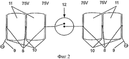
На фиг.1 схематически представлен один обогревательный элемент 1, изнашиваемый слой которого соответственно накладываемый слой (слой покрытия) образован одной паркетной планкой 2. Тип накладки (покрытия) для соответствующего изобретению отопления является, однако, несущественным. Накладка (покрытие) может быть образована точно так же доброкачественными стеновыми или потолочными элементами и, в частности, пластинами природного камня, пластинами искусственного камня, керамическими пластинами, пластинами ламината или чем-то подобным или состоять из стекла, фарфора, огнестойких бумаг, как, например, обоев, материалов Rigips или других материалов. С этой подвергающейся внешнему воздействию, в частности, износу или выставленной (под внешнее воздействие) накладкой соединена печатная плата 3, имеющая трехслойное построение. Повернутая к накладке верхняя сторона состоит из металлического проводящего материала, в частности из меди, причем главным образом это определяется тем, что речь идет об одном проводящем металлическом нанесенном покрытии. Этот металлический слой 4 законтактирован сквозь [печатную плату] по одному соединению 5 также с металлическим слоем 6 на нижней стороне печатной платы, так что на этом месте, как схематично обозначено поз.7, может быть произведено одно электрическое втыкаемое соединение к одному нулевому проводу или к заземлению, так что металлический слой 4 находится на нулевом потенциале. Отвернутая от накладки нижняя сторона печатной платы 3 несет лишь дискретные электрические сопротивления 8, причем запитывание напряжением электросети может осуществляться соответственно по втыкаемым соединениям 9. Электрическая схема включения представлена на фиг.2, причем при этом электрическом подключении соответственно внешние токопроводящие дорожки соединены с напряжением электросети, а по последовательно включенным сопротивлениям 8 убывает максимально по одной четверти напряжения электросети, так что зазоры 10 между соседними токопроводящими дорожками 11 могут выполняться соответственно малыми без опасности пробоя. Вследствие этого малого интервала электрические сопротивления 8 пролегают по всей ширине зазора и частично вступают также непосредственно в механический контакт со смежными токопроводящими дорожками 11, так что тепло диссипируется соответственно лучше.Figure 1 schematically shows one heating element 1, the wear layer of which, respectively, the applied layer (coating layer) is formed by one parquet strip 2. The type of lining (coating) for the heating according to the invention is, however, not significant. The overlay (coating) can be formed in the same way by benign wall or ceiling elements and, in particular, natural stone plates, artificial stone plates, ceramic plates, laminate plates or the like, or consist of glass, porcelain, fire-resistant papers, such as for example, wallpaper, Rigips materials, or other materials. A printed circuit board 3 having a three-layer structure is connected to this exposed to external influences, in particular wear and tear (exposed to external influences) overlay. The upper side turned towards the pad consists of a metallic conductive material, in particular copper, and this is mainly determined by the fact that we are talking about a single conductive metal coating. This metal layer 4 is contacted through the [printed circuit board] through one connection 5 also with the metal layer 6 on the underside of the printed circuit board, so that, as schematically indicated by pos. 7, one plugged-in electrical connection can be made to one neutral wire or to ground, so that the metal layer 4 is at zero potential. The bottom side of the printed circuit board 3, turned away from the lining, carries only discrete
В варианте осуществления согласно фиг.2 схематично представлен один электрический переключатель 12. Электрический переключатель 12 может быть предусмотрен на элемент в соответственно большем количестве, причем при расположении соответственно одного переключателя 12 вблизи торцевых сторон подобных элементов и при добавочном укорачивании этого элемента для приспосабливания к геометрии помещения функционирование остается полностью сохраненным, потому что другой переключатель 12 перенимает это функционирование. В закрытом состоянии этого переключателя 12 течет таким образом по обоим проводам 9 и включенным последовательно сопротивлениям 8 ток, который преобразовывается посредством сопротивлений в тепло. Малая мощность отдельных сопротивлений требует по всей площади соответственно большего количества сопротивлений.In the embodiment of FIG. 2, one
Электрическое контактирование соседних напольных элементов схематически представлено на фиг.3. Вдвинутые соответственно в пазы 13 одного электрически изолирующего перекрытия соответственно пластины 14 электрические контакты 15 видны на виде сверху на фиг.3, причем пазы, соответственно каналы, относящиеся к электрически изолирующему перекрытию, представлены на фиг.1 в поперечном сечении. Контакты 15 соединены при этом, соответственно надлежащему со стороны торца запитыванию, выборочно - с разностью потенциалов или с нулевым проводом, причем эта конфигурация впоследствии имеет место для всех в продольном направлении друг с другом соединенных элементов. Увеличенное изображение одного подобного соединительного элемента представлено на фиг.4, причем контакты 15 для ограничения глубины запрессовки соответственно втыкания имеют упор 16. Этот упор 16 одновременно может действовать как соответственно имеющая возможность деформироваться герметизирующая масса, так что торцевые стороны соседних напольных элементов могут быть защищены от проникновений воды.Electrical contacting of adjacent floor elements is shown schematically in FIG. The
Соответствующий запитывающий, соответственно подключающий элемент 16 с множеством электрических втыкаемых контактов 15 представлен на фиг.5. Эти втыкаемые контакты 15 втыкают в конце, смежном с одной стеной, и выводят по проволоке к одной подключающей детали 17, в которую после окончательной установки всего монтируемого оборудования электрические провода вкладывают и соединяют. До электрического подключения достаточно проконтролировать работоспособность соединенных соответственно в продольном направлении друг с другом элементов посредством простого измерения сопротивления, причем в заключение, как видно на фиг.6, только электрические многопроволочные провода, соответственно проволоки 18, 19 и 20 соответственно нулевому проводу заземления и фазы, единообразно для всех элементов, посредством простого изменения направления соединяют электрически с запитывающим элементом 16.The corresponding energizing, respectively connecting
Расходы на электрический монтаж таким образом снижаются до минимума и этого достаточно, чтобы подверженные излому электрические подводящие провода укладывать как кольцевые линии вблизи подключения со стороны стены, причем здесь на основании необходимых термических расширительных зазоров имеется в распоряжении также одна соответствующая площадка для размещения этих проводов механически защищенным образом.Thus, the costs of electrical installation are reduced to a minimum and this is enough to lay electrical supply wires subject to kink as ring lines near the connection on the wall side, and here, on the basis of the necessary thermal expansion gaps, there is also one appropriate platform for placing these wires mechanically protected way.
Контроль значений сопротивления может осуществляться и при эксплуатации для того, чтобы распознавать нарушения в работе.Resistance values can also be monitored during operation in order to recognize malfunctions.
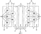
На фиг.7 видно, что сопротивления 8, расположенные между соседними токопроводящими дорожками 11, перемыкают электрически изолированный зазор между токопроводящими дорожками 11, так что также обеспечена соответствующая теплопередача к соответствующим плоскостным токопроводящим дорожкам 11. Расположенные в соседних рядах и подключенные последовательно друг с другом сопротивления 8 при этом, как видно на фиг.7, расположены на выемке для того, чтобы соответственно способствовать и выравнивать схематично обозначенное окружностями 21 распространение тепла по площади.Figure 7 shows that
Схематично на фиг.7 нанесенное как проволочное соединение перемыкание нулевого провода соответственно корпуса [массы] для достижения последовательного подключения обеспечено, естественно, посредством одного соответствующего переключателя, как он показан на фиг.2 и не изображен на фиг.7 ради обзорности.Schematically in Fig. 7, the interconnection of the neutral wire, applied as a wire connection, to the case [mass], in order to achieve a series connection, is naturally provided by means of one corresponding switch, as shown in Fig. 2 and not shown in Fig. 7 for the sake of visibility.
Claims (16)
Applications Claiming Priority (3)
| Application Number | Priority Date | Filing Date | Title |
|---|---|---|---|
| ATA2081/2006 | 2006-12-18 | ||
| AT0208106A AT504216B1 (en) | 2006-12-18 | 2006-12-18 | Element for producing electrically heatable covering with connecting elements, is connected to multilayer printed circuit board, whose electrically conductive surface facing element are connected to electrical contact |
| PCT/AT2007/000569 WO2008074041A2 (en) | 2006-12-18 | 2007-12-18 | Heatable element |
Publications (2)
| Publication Number | Publication Date |
|---|---|
| RU2009127811A RU2009127811A (en) | 2011-01-27 |
| RU2496060C2 true RU2496060C2 (en) | 2013-10-20 |
Family
ID=39186013
Family Applications (1)
| Application Number | Title | Priority Date | Filing Date |
|---|---|---|---|
| RU2009127811/12A RU2496060C2 (en) | 2006-12-18 | 2007-12-18 | Heating element |
Country Status (6)
| Country | Link |
|---|---|
| US (1) | US20100012642A1 (en) |
| EP (1) | EP2097681A2 (en) |
| AT (1) | AT504216B1 (en) |
| CA (1) | CA2673167A1 (en) |
| RU (1) | RU2496060C2 (en) |
| WO (1) | WO2008074041A2 (en) |
Cited By (1)
| Publication number | Priority date | Publication date | Assignee | Title |
|---|---|---|---|---|
| RU198198U1 (en) * | 2020-03-05 | 2020-06-23 | Дмитрий Леонидович Стрельцов | GLASSWARE WITH ZONED ELECTRIC HEATED SURFACE |
Families Citing this family (6)
| Publication number | Priority date | Publication date | Assignee | Title |
|---|---|---|---|---|
| DE102013215522A1 (en) * | 2013-08-07 | 2015-02-12 | Robert Bosch Gmbh | Sensor device for determining at least one parameter of a fluid flowing through a channel |
| DE102013016874A1 (en) * | 2013-10-11 | 2015-04-30 | Rwe Ag | Floor element for electrical installations and system with floor elements |
| US20160014847A1 (en) * | 2013-12-11 | 2016-01-14 | Marudeoham, Inc. | Self-assembly electric mat |
| AT14867U1 (en) * | 2014-02-06 | 2016-07-15 | Gl & Partners Og | radiator |
| EP3006834A1 (en) * | 2014-10-09 | 2016-04-13 | Protion GmbH | Area air conditioning system |
| CN109028261B (en) * | 2018-07-19 | 2024-01-30 | 珠海格力电器股份有限公司 | Electrothermal film heater and assembly method thereof |
Citations (5)
| Publication number | Priority date | Publication date | Assignee | Title |
|---|---|---|---|---|
| GB900515A (en) * | 1957-07-08 | 1962-07-04 | Eisler Paul | Electric surface heating devices |
| JPH04190021A (en) * | 1990-11-26 | 1992-07-08 | Nippon Tungsten Co Ltd | Panel heater |
| GB2361398B (en) * | 1998-10-27 | 2003-09-03 | Molekulare Energietechnik Ag | Heating arrangement |
| DE20218331U1 (en) * | 2002-11-25 | 2004-04-01 | Alloc A/S | Heated floor panel |
| DE202005019835U1 (en) * | 2005-12-16 | 2006-03-09 | Moletherm Holding Ag | Electrically operable Flächenheizelement arrangement, in particular as a floor-Flächenheizelement arrangement |
Family Cites Families (9)
| Publication number | Priority date | Publication date | Assignee | Title |
|---|---|---|---|---|
| GB739564A (en) * | 1953-06-23 | 1955-11-02 | Saint Gobain | Improvements in or relating to electric resistance heaters |
| JPS59205178A (en) * | 1983-05-06 | 1984-11-20 | 松下電器産業株式会社 | Heat collecting implement |
| US5180900A (en) * | 1991-04-15 | 1993-01-19 | Tapeswitch Corporation Of America | Electrical resistance element with heat-sensitive disconnect capability |
| US5198640A (en) * | 1991-05-28 | 1993-03-30 | Yang Chiung Hsiang | Fully clad electric ptc heater with a finned protective casing |
| US5592647A (en) * | 1991-08-26 | 1997-01-07 | Nippon Tungsten Co., Ltd. | PTC panel heater with small rush current characteristic and highly heat insulating region corresponding to heater location to prevent local overheating |
| US7423239B2 (en) * | 2003-05-28 | 2008-09-09 | Saint-Gobain Glass France | Laminated element provided with a heated layer |
| US20060065431A1 (en) * | 2004-09-29 | 2006-03-30 | Trucco Horacio A | Self-reflowing printed circuit board and application methods |
| US7488551B2 (en) * | 2004-12-28 | 2009-02-10 | Ballard Power Systems Inc. | Integrated current collector and electrical component plate for a fuel cell stack |
| DE202005000886U1 (en) * | 2005-01-19 | 2006-06-29 | Kronospan Technical Co. Ltd., Engomi | Heating device for wall, ceiling or floor coverings |
-
2006
- 2006-12-18 AT AT0208106A patent/AT504216B1/en not_active IP Right Cessation
-
2007
- 2007-12-18 EP EP07845297A patent/EP2097681A2/en not_active Withdrawn
- 2007-12-18 CA CA002673167A patent/CA2673167A1/en not_active Abandoned
- 2007-12-18 US US12/448,316 patent/US20100012642A1/en not_active Abandoned
- 2007-12-18 RU RU2009127811/12A patent/RU2496060C2/en not_active Application Discontinuation
- 2007-12-18 WO PCT/AT2007/000569 patent/WO2008074041A2/en active Application Filing
Patent Citations (5)
| Publication number | Priority date | Publication date | Assignee | Title |
|---|---|---|---|---|
| GB900515A (en) * | 1957-07-08 | 1962-07-04 | Eisler Paul | Electric surface heating devices |
| JPH04190021A (en) * | 1990-11-26 | 1992-07-08 | Nippon Tungsten Co Ltd | Panel heater |
| GB2361398B (en) * | 1998-10-27 | 2003-09-03 | Molekulare Energietechnik Ag | Heating arrangement |
| DE20218331U1 (en) * | 2002-11-25 | 2004-04-01 | Alloc A/S | Heated floor panel |
| DE202005019835U1 (en) * | 2005-12-16 | 2006-03-09 | Moletherm Holding Ag | Electrically operable Flächenheizelement arrangement, in particular as a floor-Flächenheizelement arrangement |
Cited By (1)
| Publication number | Priority date | Publication date | Assignee | Title |
|---|---|---|---|---|
| RU198198U1 (en) * | 2020-03-05 | 2020-06-23 | Дмитрий Леонидович Стрельцов | GLASSWARE WITH ZONED ELECTRIC HEATED SURFACE |
Also Published As
| Publication number | Publication date |
|---|---|
| EP2097681A2 (en) | 2009-09-09 |
| WO2008074041A3 (en) | 2008-08-28 |
| AT504216A4 (en) | 2008-04-15 |
| RU2009127811A (en) | 2011-01-27 |
| WO2008074041A2 (en) | 2008-06-26 |
| AT504216B1 (en) | 2008-04-15 |
| CA2673167A1 (en) | 2008-06-26 |
| US20100012642A1 (en) | 2010-01-21 |
Similar Documents
| Publication | Publication Date | Title |
|---|---|---|
| RU2496060C2 (en) | Heating element | |
| US6426489B1 (en) | Flat resistance heating element | |
| US5380988A (en) | Heated mat structure for melting ice and snow | |
| US5004190A (en) | Rail heating apparatus | |
| JP2011518419A (en) | Floor heating element for floor heating | |
| CN101395486A (en) | Stacked guard structures | |
| EP2461643A1 (en) | Electrical safety grounding system | |
| EP2781843A1 (en) | Manufacture of modular flooring with an electrical heating system | |
| WO2007115559A3 (en) | Insulating panel with a heating function and surface heating system | |
| EP1933096A2 (en) | Heating panel | |
| JP3132051U (en) | Film heater | |
| US20120140362A1 (en) | Method of Operating a Heating Element for Underfloor Heating | |
| US11054149B2 (en) | Sectionable floor heating system | |
| EP1410706A2 (en) | Electrical convective panel heater | |
| EP2401556B1 (en) | Planar electrode system | |
| JP3948375B2 (en) | Exothermic sheet and floor heating construction method using the exothermic sheet | |
| GB2555925A (en) | Underfloor heating | |
| KR20230158312A (en) | Floor finishing construction structure including grounding film | |
| CA3117696A1 (en) | Sectionable floor heating system | |
| CA2982149A1 (en) | Electric heating system, electric heating panel, method of manufacturing thereof, laying structure thereof, and laying method thereof | |
| JPH0878139A (en) | Surface heating element, and constructing method of heating equipment using this surface heating element | |
| NL1025456C2 (en) | Heated floor covering, such as laminate, parquet or carpet, comprises several accurately connected floor panels | |
| WO2009107118A2 (en) | A panel heater | |
| JP2000121083A (en) | Rubber-chip electric floor heating panel and system | |
| TH39700B (en) | Hardwired circuit board |
Legal Events
| Date | Code | Title | Description |
|---|---|---|---|
| FA93 | Acknowledgement of application withdrawn (no request for examination) |
Effective date: 20101220 |
|
| FZ9A | Application not withdrawn (correction of the notice of withdrawal) |
Effective date: 20111216 |