RU2479704C2 - Window closing facility and control mechanism - Google Patents
Window closing facility and control mechanism Download PDFInfo
- Publication number
- RU2479704C2 RU2479704C2 RU2011131825/12A RU2011131825A RU2479704C2 RU 2479704 C2 RU2479704 C2 RU 2479704C2 RU 2011131825/12 A RU2011131825/12 A RU 2011131825/12A RU 2011131825 A RU2011131825 A RU 2011131825A RU 2479704 C2 RU2479704 C2 RU 2479704C2
- Authority
- RU
- Russia
- Prior art keywords
- axis
- cord
- spring
- lifting
- winding
- Prior art date
Links
Images


Classifications
-
- E—FIXED CONSTRUCTIONS
- E06—DOORS, WINDOWS, SHUTTERS, OR ROLLER BLINDS IN GENERAL; LADDERS
- E06B—FIXED OR MOVABLE CLOSURES FOR OPENINGS IN BUILDINGS, VEHICLES, FENCES OR LIKE ENCLOSURES IN GENERAL, e.g. DOORS, WINDOWS, BLINDS, GATES
- E06B9/00—Screening or protective devices for wall or similar openings, with or without operating or securing mechanisms; Closures of similar construction
- E06B9/24—Screens or other constructions affording protection against light, especially against sunshine; Similar screens for privacy or appearance; Slat blinds
- E06B9/26—Lamellar or like blinds, e.g. venetian blinds
- E06B9/28—Lamellar or like blinds, e.g. venetian blinds with horizontal lamellae, e.g. non-liftable
- E06B9/30—Lamellar or like blinds, e.g. venetian blinds with horizontal lamellae, e.g. non-liftable liftable
- E06B9/32—Operating, guiding, or securing devices therefor
- E06B9/322—Details of operating devices, e.g. pulleys, brakes, spring drums, drives
- E06B2009/3222—Cordless, i.e. user interface without cords
-
- E—FIXED CONSTRUCTIONS
- E06—DOORS, WINDOWS, SHUTTERS, OR ROLLER BLINDS IN GENERAL; LADDERS
- E06B—FIXED OR MOVABLE CLOSURES FOR OPENINGS IN BUILDINGS, VEHICLES, FENCES OR LIKE ENCLOSURES IN GENERAL, e.g. DOORS, WINDOWS, BLINDS, GATES
- E06B9/00—Screening or protective devices for wall or similar openings, with or without operating or securing mechanisms; Closures of similar construction
- E06B9/24—Screens or other constructions affording protection against light, especially against sunshine; Similar screens for privacy or appearance; Slat blinds
- E06B9/26—Lamellar or like blinds, e.g. venetian blinds
- E06B9/28—Lamellar or like blinds, e.g. venetian blinds with horizontal lamellae, e.g. non-liftable
- E06B9/30—Lamellar or like blinds, e.g. venetian blinds with horizontal lamellae, e.g. non-liftable liftable
- E06B9/32—Operating, guiding, or securing devices therefor
- E06B9/322—Details of operating devices, e.g. pulleys, brakes, spring drums, drives
- E06B2009/3225—Arrangements to aid the winding of cords rollers
-
- E—FIXED CONSTRUCTIONS
- E06—DOORS, WINDOWS, SHUTTERS, OR ROLLER BLINDS IN GENERAL; LADDERS
- E06B—FIXED OR MOVABLE CLOSURES FOR OPENINGS IN BUILDINGS, VEHICLES, FENCES OR LIKE ENCLOSURES IN GENERAL, e.g. DOORS, WINDOWS, BLINDS, GATES
- E06B9/00—Screening or protective devices for wall or similar openings, with or without operating or securing mechanisms; Closures of similar construction
- E06B9/56—Operating, guiding or securing devices or arrangements for roll-type closures; Spring drums; Tape drums; Counterweighting arrangements therefor
- E06B9/60—Spring drums operated only by closure members
Abstract
Description
Настоящее изобретение относится к оконному закрывающему средству, которое может быть поднято без необходимости применения усилия, или для регулирующего механизма, или для самого оконного закрывающего средства по мере того, как оконное закрывающее средство открывается. В частности, настоящее изобретение относится к оконному закрывающему средству, имеющему регулирующий механизм, выполненный с возможностью прикладывания направленного вверх усилия на элемент шторы и нижнюю направляющую, которое является достаточной величины для подъема элемента шторы и нижней направляющей без дополнительного усилия, приложенного пользователем во время подъема.The present invention relates to window closing means that can be lifted without the need for force, either for the adjusting mechanism or for the window closing means itself as the window closing means opens. In particular, the present invention relates to window closing means having a control mechanism configured to apply an upward force on the curtain element and the lower guide, which is sufficient to lift the curtain element and the lower guide without additional effort exerted by the user during the lifting.
Оконные шторы и закрывающие средства являются основой многих приложений и используются для регулирования количества света, входящего в комнату, и для обеспечения эстетической привлекательности к декору. Такие оконные шторы и закрывающие средства принимают множество форм, включающих в себя рулонные шторы, римские шторы, подъемные жалюзи и ячеистые шторы. Обычные ячеистые или шторы-плиссе применяют шнур, шнуровые фиксаторы или передающие механизмы для подъема, опускания и размещения закрывающего средства в необходимом положении. Для оконных закрывающих средств, применяющих шнуровой фиксатор, шнуры проходят вверх через складчатую ткань, поперек внутренности верхней направляющей и выходят через блокирующий механизм. Другие ячеистые шторы включают в себя передающий механизм и непрерывный петлевой шнур, который оттягивается пользователем для подъема и опускания оконной шторы. Римские шторы и подъемные жалюзи также имеют тенденцию включать в себя шнуры для подъема, которые прикрепляются к нижней рейке или нижней направляющей.Window curtains and closing means are the basis of many applications and are used to regulate the amount of light entering the room and to provide aesthetic appeal to the decor. Such window blinds and closing means take many forms, including roller blinds, Roman blinds, lifting blinds and cellular curtains. Conventional cellular or pleated blinds use a cord, cord clamps or transmission mechanisms to raise, lower and place the closure in the required position. For window closers using a cord lock, the cords extend upward through the pleated fabric across the inside of the upper guide and exit through the locking mechanism. Other cellular curtains include a transmission mechanism and a continuous loop cord that is pulled by the user to raise and lower the window curtain. Roman blinds and lifting blinds also tend to include lifting cords that attach to the lower rail or lower rail.
Имеются некоторые недостатки этих проектов. Шнуры представляют потенциальный риск попадания или удушения ребенка внешним регулирующим шнуром. Шнуры также имеют тенденцию отвлекать от эстетики оконного закрывающего средства в том, что они продолжаются вдоль лицевой поверхности оконного закрывающего средства и, когда оконная штора открыта, должны быть или завернуты на крючок или просто оставлены на полу. Для оконных закрывающих средств, которые используют шнуровые фиксаторы, шнуры также подвергаются по существу истиранию из-за трения относительно поверхностей как результат подъема и опускания закрывающего средства.There are some drawbacks to these projects. Cords present the potential risk of a child getting strangled or strangled with an external control cord. Cords also tend to distract from the aesthetics of the window closure in that they extend along the front surface of the window closure and, when the window shade is open, must either be hooked or simply left on the floor. For window closers that use cord locks, the cords also undergo substantially abrasion due to friction against surfaces as a result of raising and lowering the closure.
Другие оконные закрывающие средства включают в себя обычные рулонные шторы, которые действуют в отсутствие шнура. Эти рулонные шторы включают в себя втягивающий механизм намотки крутильной пружиной в сочетании с зажимным или блокирующим механизмом, установленным с роллером, на котором штора скручивается и собирается. В действии рулонная штора оттягивается вниз пользователем до необходимого местоположения, где она блокируется на месте зажимным или блокирующим механизмом. Для разблокирования и освобождения шторы так, что она может быть поднята, пользователь обычно тянет нижнюю направляющую шторы на себя, удлиняя штору достаточно для расцепления внутреннего зажимного или блокирующего механизма в ней. Когда зажимной или блокирующий механизм расцеплен и пользователь освобождает штору, штора втягивается, используя втягивающий механизм, ведомый крутильной пружиной. Известные рулонные шторы, однако, являются функциональными с плоским материалом шторы, который закатывает аккуратно в ограниченное местоположение.Other window closers include conventional roller blinds that operate in the absence of a cord. These roller blinds include a coil spring retractor in combination with a clamping or locking mechanism mounted with a roller on which the curtain is twisted and assembled. In action, the roller blind is pulled down by the user to the desired location, where it is locked in place by a clamping or locking mechanism. To unlock and release the curtain so that it can be lifted, the user usually pulls the lower guide of the curtain toward him, lengthening the curtain enough to disengage the internal clamping or locking mechanism in it. When the clamping or locking mechanism is disengaged and the user releases the curtain, the curtain is retracted using a retractor driven by a torsion spring. Known roller blinds, however, are functional with a flat curtain material that rolls neatly into a limited location.
Механизм, используемый в такой рулонной шторе, не совместим с другими оконными закрывающими средствами, такими как ячеистые шторы, подъемные жалюзи и римские шторы. По мере того как рулонные шторы поднимаются, размер поднимаемой шторы уменьшается так, что пружинный элемент постоянной крутильной силы способен применить необходимое наматывание или действующую вверх силу по всему диапазону открывания. В отличие от этого подобный механизм поднятия обычно является неподходящим в ячеистых шторах, подъемных жалюзи и римских шторах. В этих типах оконных закрывающих средств материал элемента шторы обычно собирается подъемным нижним элементом, таким как нижняя направляющая, и увеличивающиеся величины веса собираются на нижнем элементе по мере того, как оконное закрывающее средство поднимается. Причина этого состоит в том, что материал шторы или элемента шторы все более складывается на нижнюю направляющую по мере того, как нижняя направляющая поднимается, что увеличивает нагрузку на подъемный механизм.The mechanism used in such a roller blind is not compatible with other window closing means, such as cellular curtains, lifting blinds and Roman blinds. As the roller blinds rise, the size of the curtain to be lifted decreases so that the spring element of constant torsional force is able to apply the necessary winding or upward force over the entire opening range. In contrast, a similar lifting mechanism is usually unsuitable in cellular curtains, lifting blinds and Roman blinds. In these types of window closing means, the material of the curtain element is usually collected by the lifting lower element, such as the lower guide, and increasing weight values are collected on the lower element as the window closing means rises. The reason for this is that the material of the curtain or element of the curtain is more and more being folded onto the lower guide as the lower guide rises, which increases the load on the lifting mechanism.
Для того чтобы привести в соответствие возрастающий вес, очень сильные крутящие пружины используются для размещения максимального веса шторы. Один недостаток этого подхода, однако, состоит в том, что скорость, при которой оконное закрывающее средство втягивается, может быть слишком быстрой и неконтролируемой. Одна попытка решить эту проблему обоснована в патенте США № 6666252, выданном на имя Welfonder. Этот патент изучает использование гидравлического тормоза для регулирования скорости, при которой шнуры для подъема втягиваются на всем протяжении процесса подъема. Другой подход, который использовался, показан в патенте США № 6056036, выданном на имя Todd, который применяет элемент механического трения для постоянной медленной скорости втягивания. Одна проблема имеется при этом подходе, что применяемая пружина вызывает напряжение, которое осложняет преодоление его для пользователя в тот момент, когда он пытается опустить штору. Избыточное тянущее усилие, развиваемое пользователем, часто приводит к повреждению оконного закрывающего средства.In order to match the increasing weight, very strong torque springs are used to accommodate the maximum weight of the curtain. One drawback of this approach, however, is that the speed at which the window closure is retracted may be too fast and uncontrollable. One attempt to solve this problem is justified in US patent No. 6666252, issued in the name of Welfonder. This patent examines the use of a hydraulic brake to control the speed at which the lifting cords are pulled in throughout the lifting process. Another approach that was used is shown in US Pat. No. 6,056,036 to Todd, which uses a mechanical friction element for a constant slow retraction speed. One problem with this approach is that the spring applied causes stress, which makes it difficult for the user to overcome it when he tries to lower the curtain. Excessive pulling force developed by the user often leads to damage to the window closure.
В качестве альтернативы использовались пружины с переменной жесткостью. Такие пружины с переменной жесткостью являются по существу более сложными в использовании и изготовлении.As an alternative, springs with variable stiffness were used. Such variable stiffness springs are substantially more difficult to use and manufacture.
Следовательно, существует необходимость в механизме подъема оконного закрывающего средства для оконных закрывающих средств, таких как подъемные жалюзи, ячеистые шторы и римские шторы, который является самоподнимающимся и решает вышеупомянутые проблемы.Therefore, there is a need for a window closing mechanism for window closing means, such as lifting blinds, mesh curtains and Roman curtains, which is self-lifting and solves the above problems.
Настоящее изобретение относится к самоподнимающемуся оконному закрывающему средству и регулирующему механизму для оконного закрывающего средства. В частности, оконное закрывающее средство является самоподнимающимся оконным закрывающим средством, которое включает в себя верхнюю направляющую, элемент шторы, такой как ячеистая панель, пластины жалюзи или римский материал шторы, нижнюю направляющую, по меньшей мере, один шнур для подъема, функционально присоединенный у первого конца к нижней направляющей, и регулирующий механизм. Верхняя направляющая может определять вытянутую канавку, при этом в ней размещается регулирующий механизм. В некоторых вариантах осуществления регулирующий механизм включает в себя приводную ось и устройство привода, функционально связанное с приводной осью. Устройство привода, которым может быть пружина с постоянной жесткостью, обеспечивает по существу постоянную вращательную силу на приводную ось.The present invention relates to a self-lifting window closure and a regulating mechanism for window closing means. In particular, the window closing means is a self-rising window closing means that includes an upper guide, a curtain element such as a mesh panel, louvre plates or Roman curtain material, a lower guide, at least one lift cord, functionally attached to the first end to lower guide, and adjusting mechanism. The upper guide can determine the elongated groove, while the regulating mechanism is placed in it. In some embodiments, the control mechanism includes a drive axis and a drive device operably coupled to the drive axis. A drive device, which may be a spring with constant stiffness, provides a substantially constant rotational force on the drive axis.
По меньшей мере, один узел для намотки шнура также установлен коаксиально относительно приводной оси. Обычно число узлов для намотки шнура будет таким же, как и число шнуров для подъема. Однако в отдельных случаях один узел для намотки шнура может быть приспособлен для действия с многочисленными шнурами. Узел для намотки шнура включает в себя, по меньшей мере, один намоточный барабан, функционально связанный со вторым концом шнура для подъема и имеющий конусный участок. Узел для намотки шнура также включает в себя установочный элемент для перемещения узла для намотки шнура вбок вдоль оси привода при вращении установочного элемента. В предпочтительном варианте осуществления установочным элементом является резьбовой трубчатый элемент, связанный с намоточным барабаном. Узел для намотки шнура приспособлен для преобразования вращательной силы на приводную ось в подъемную силу на шнур для подъема, при этом подъемная сила больше, чем общая, направленная вниз, сила, приложенная элементом шторы и нижней направляющей по всему диапазону открытия и закрытия. В настоящем предпочтительном варианте осуществления узел для намотки шнура вращательно закреплен с приводной осью посредством элемента втулки, приспособленного для зацепления узла для намотки шнура и приводной оси. Элемент втулки может находиться в скользящем соотношении с конусным участком узла для намотки шнура.At least one cord winding assembly is also mounted coaxially with respect to the drive axis. Usually the number of knots for winding the cord will be the same as the number of cords for lifting. However, in some cases, one node for winding the cord can be adapted to operate with multiple cords. The cord winding assembly includes at least one winding drum operably coupled to a second end of the lifting cord and having a tapered portion. The cord winding assembly also includes a mounting member for moving the cord winding assembly sideways along the axis of the drive while rotating the mounting member. In a preferred embodiment, the mounting member is a threaded tubular member associated with a winding drum. The cord winding assembly is adapted to convert rotational force on the drive axle into lifting force on a lifting cord, wherein the lifting force is greater than the total downward force exerted by the curtain element and the lower guide over the entire opening and closing range. In the present preferred embodiment, the cord winding assembly is rotationally fixed to the drive axis by a sleeve member adapted to engage the cord winding assembly and the drive axis. The sleeve element may be in a sliding relationship with the conical portion of the cord winding assembly.
Зажимное приспособление, или элемент блокировки, также функционально связано с приводной осью и приспособлено для разблокирования приводной оси в необходимом положении. В предпочтительном варианте осуществления зажимное приспособление содержит средство с возвратно-поступательным перемещением, размещенное коаксиально относительно приводной оси и перемещаемое между положением разблокирования и положением блокировки, и пружинный элемент, присоединенный к элементу с возвратно-поступательным перемещением и действующий или для усиления или ослабления закрепления элемента с возвратно-поступательным перемещением на приводной оси. Средство с возвратно-поступательным перемещением сконфигурировано для того, чтобы заставить пружинный элемент зажаться на приводной оси в положении блокировки для блокирования вращения приводной оси против вращательной силы, приложенной устройством привода, и чтобы заставить пружинный элемент ослабить зажатие приводной оси в положении разблокирования для позволения вращения приводной оси под действием вращательной силы, приложенной устройством привода.The clamping device, or locking element, is also functionally connected to the drive axle and is adapted to unlock the drive axle in the required position. In a preferred embodiment, the clamping device comprises reciprocating means arranged coaxially with respect to the drive axis and movable between the unlocking position and the locking position, and a spring element connected to the reciprocating element and acting to either strengthen or loosen the element reciprocating movement on the drive axle. The reciprocating means is configured to cause the spring element to be clamped on the drive axis in the locked position to block rotation of the drive axis against the rotational force exerted by the drive device, and to cause the spring element to loosen the clamp of the drive axis in the unlocked position to allow rotation of the drive axis under the action of rotational force applied by the drive device.
Сущность изобретения поясняется на чертежах, где:The invention is illustrated in the drawings, where:
фиг.1 представляет собой вид в перспективе, частично в разрезе, предпочтительного варианта осуществления оконного закрывающего средства согласно настоящему изобретению;figure 1 is a perspective view, partially in section, of a preferred embodiment of a window covering means according to the present invention;
фиг.2 представляет собой вид в перспективе с пространственным разделением деталей элемента привода одинарной витой пружины согласно фиг.1;figure 2 is a perspective view with a spatial separation of the parts of the drive element of a single coil spring according to figure 1;
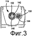
фиг.3 представляет собой вид в боковом разрезе элемента привода одинарной витой пружины;figure 3 is a side view of a drive element of a single coil spring;
фиг.4 представляет собой вид в боковом разрезе альтернативного элемента привода одинарной витой пружины;Fig. 4 is a side sectional view of an alternative single coil spring drive member;
фиг.5 представляет собой вид в боковом разрезе элемента привода двойной витой пружины;FIG. 5 is a side sectional view of a double coil spring drive member; FIG.
фиг.6 представляет собой вид в боковом разрезе альтернативного элемента привода двойной витой пружины;FIG. 6 is a side sectional view of an alternative dual coil spring drive member; FIG.
фиг.7 представляет собой вид в перспективе с пространственным разделением деталей узла намотки шнура, изображенного на фиг.1;Fig.7 is a perspective view with a spatial separation of the parts of the node winding cord shown in Fig.1;
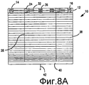
фиг.8А представляет собой вид спереди оконного закрывающего средства согласно фиг.1 в закрытом положении и с верхней направляющей в разрезе;figa is a front view of the window closing means according to figure 1 in the closed position and with the upper guide in section;
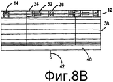
фиг.8В представляет собой вид спереди оконного закрывающего средства согласно фиг.1 в частично открытом положении и с верхней направляющей в разрезе;Fig. 8B is a front view of the window closing means according to Fig. 1 in a partially open position and with a top guide in section;
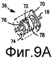
фиг.9А представляет собой вид в перспективе предпочтительного зажимного приспособления, когда оконное закрывающее средство находится в полностью поднятом положении;figa is a perspective view of a preferred clamping device when the window closing means is in the fully raised position;
фиг.9В представляет собой вид в разрезе зажимного приспособления согласно фиг.9А;figv is a view in section of the clamping device according figa;
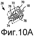
фиг.10А представляет собой вид в перспективе зажимного приспособления согласно фиг.9А, когда пользователь оттягивает вниз оконное закрывающее средство;figa is a perspective view of the clamping device according figa, when the user pulls down the window closing means;
фиг.10В представляет собой вид в разрезе зажимного приспособления согласно фиг.10А;figv is a view in section of a clamping device according to figa;
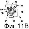
фиг.11А представляет собой вид в перспективе зажимного приспособления согласно фиг.9А, когда пользователь разблокирует оконное закрывающее средство;figa is a perspective view of the clamping device according figa, when the user unlocks the window closing means;
фиг.11В представляет собой вид в разрезе зажимного приспособления согласно фиг.11А;11B is a sectional view of the jig according to FIG. 11A;
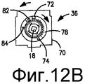
фиг.12А представляет собой вид в перспективе зажимного приспособления согласно фиг.9А, когда пользователь оттягивает вниз оконное закрывающее средство, чтобы разблокировать зажимное приспособление;figa is a perspective view of the clamping device according to figa, when the user pulls down the window closing means to unlock the clamping device;
фиг.12В представляет собой вид в разрезе зажимного приспособления согласно фиг.12А;figv is a view in section of a clamping device according figa;
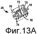
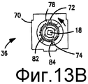
фиг.13А представляет собой вид в перспективе зажимного приспособления согласно фиг.9А, когда оконное закрывающее средство самостоятельно поднимается;figa is a perspective view of the clamping device according to figa, when the window closing means independently rises;
фиг.13В представляет собой вид в разрезе зажимного приспособления согласно фиг.13А;figv is a view in section of the clamping device according figa;
фиг.14 представляет собой вид в перспективе альтернативного варианта осуществления оконного закрывающего средства согласно настоящему изобретению с тормозным элементом;Fig. 14 is a perspective view of an alternative embodiment of a window closing means according to the present invention with a brake element;
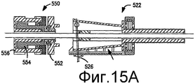
фиг.15А представляет собой вид в боковом разрезе тормозного элемента согласно фиг.14, отцепленного от одного узла намотки шнура;figa is a side view in section of the brake element according to fig.14, detached from one node of the cord winding;
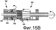
фиг.15В представляет собой вид в боковом разрезе тормозного элемента согласно фиг.14, сцепляющего один узел намотки шнура;FIG. 15B is a side cross-sectional view of the brake element of FIG. 14 interlocking one cord winding assembly; FIG.
фиг.15С представляет собой вид в боковом разрезе тормозного элемента согласно фиг.14, когда оконное закрывающее средство полностью поднято.FIG. 15C is a side sectional view of the brake member of FIG. 14 when the window closing means is fully raised.
Данное изобретение, раскрытое ниже, допустимо для осуществления во многих различных видах. Варианты, показанные в чертежах и подробно описанные здесь и ниже, являются предпочтительными вариантами осуществления настоящего изобретения. Настоящее раскрытие, однако, представляет собой только пример первооснов и признаков данного изобретения и не ограничивает изобретение на примерных вариантах осуществления.The invention disclosed below is valid for implementation in many different forms. The options shown in the drawings and described in detail here and below are preferred embodiments of the present invention. The present disclosure, however, is only an example of the primary principles and features of the present invention and does not limit the invention to exemplary embodiments.
На фиг.1 представлен вариант осуществления самоподнимающегося оконного закрывающего средства 10 согласно настоящему изобретению. Предусмотрена верхняя направляющая 12, ограничивающая канавку. Пара приводных устройств, таких как пружинные устройства 14 и 16, коаксиально установлены вокруг приводной оси 18. Также на приводной оси 18 установлены узлы 20 и 22 для намотки шнура. Каждый из узлов 20 и 22 для намотки шнура включает в себя намоточный барабан 24 и 26 в форме усеченного конуса и резьбовой трубчатый элемент 32 и 34 соответственно. Шнуры 28 и 30 для подъема, которые изображены в виде намотки на намоточные барабаны 24 и 26, прикреплены у конца намоточных барабанов 24 и 26. В этом варианте осуществления зажимное приспособление 36 также предусмотрено и коаксиально установлено на приводной оси 18. Каждый из этих компонентов подробно обсуждается ниже. Оконное закрывающее средство 10 дополнительно включает в себя элемент шторы, такой как ячеистый материал 38 шторы, и нижний элемент, такой как нижняя направляющая 40. Термин «шнур» по мере использования может охватывать шнур, полоску, ленту, веревку или подобные гибкие вытянутые элементы, которые являются подходящими для поддержания подвешенного элемента шторы и которые могут быть намотаны и размотаны для развертывания и втягивания элемента шторы. Относительно короткая длина шнура 42 также может быть обеспечена, так что пользователь может оттянуть вниз оконное закрывающее средство и, как будет подробно обсуждаться ниже, разблокировать зажимное приспособление так, что оконное закрывающее средство будет втягивать себя.1 shows an embodiment of a self-lifting window closing means 10 according to the present invention. An
На фиг.2 показан предпочтительный вариант осуществления пружинного устройства 14. Пружинное устройство 14 содержит корпус 42 для пружины, который закрыт крышкой 48. Витая пружина 46 и ось 44 пружины закреплены внутри корпуса 42, который закрыт крышкой 48. Первый конец 50 витой пружины 46 прикреплен к оси 44 пружины, которая коаксиально присоединена к приводной оси 18 (фиг.1). В этом предпочтительном варианте осуществления витая пружина сконфигурирована для обеспечения достаточного вращательного усилия к приводной оси 18 и намоточным барабанам 24 и 26 для подъема элемента шторы и нижней направляющей. Другие альтернативные варианты осуществления пружинных устройств также являются возможными, такие как показанные на фиг.3-6.Figure 2 shows a preferred embodiment of the
Например, подходящее пружинное устройство 114, показанное на фиг.3, может включать в себя витой пружинный элемент 146, имеющий первый конец, закрепленный с первой осью 142 пружины, которая присоединяется к приводной оси 18, изображенной на фиг.1, и второй конец, закрепленный со второй осью 144 пружины, которая смещена от первой оси 142 пружины. Витая пружина 146 в расслабленном положении может быть изначально намотана вокруг оси 144 второй пружины. По мере того как элемент шторы оттягивается вниз, витая пружина 146 может вытягиваться от оси 144 второй пружины и поступательно обматываться вокруг оси 142 первой пружины. Эта конфигурация пружинного элемента 114 может быть подходящей, когда используемая витая пружина 146 имеет большую длину для позволения более длинного диапазона размещения элемента шторы.For example, a
На фиг.4 изображено другое подходящее пружинное устройство 214, которое подобно варианту осуществления, показанному на фиг.3, за исключением того, что второй конец витой пружины не соединяется ни с какой осью второй пружины. Вместо этого витая пружина 246 наматывается на себя у своего второго конца, в то время как первый конец 252 витой пружины 246 присоединяется к оси 218 одинарной пружины, присоединенной к приводной оси 18, показанной на фиг.1.Figure 4 shows another
Кроме того, другие подходящие варианты осуществления изображены на фиг.5 и 6. На фиг.5 пружинное устройство 314 включает в себя узел двух витых пружин 346 и 348, который может быть использован для обеспечения большей подъемной силы для элемента шторы. Эта первая витая пружина 346 имеет свой первый конец, присоединенный к оси 344 первой пружины, и вторая витая пружина 348 имеет свой первый конец, присоединенный к оси 345 второй пружины. Второй конец первой витой пружины 346 и второй конец второй витой пружины 348 соответственно присоединены к оси 318 третьей пружины, размещенной между осями 344 и 345 первой и второй пружины и присоединенной к приводной оси 18. По мере того как элемент шторы оттягивается вниз, витые пружины 346 и 348 могут соответственно вытянуться от оси 344 и 345 первой и второй пружины для поступательной обмотки вокруг оси 318 третьей пружины для приложения увеличенной подъемной силы на приводную ось 18. На фиг.6 изображенный вариант осуществления очень похож на тот, который показан на фиг.5, за исключением того, что две витые пружины 446 и 448, которые намотаны на ось 418, присоединенную к приводной оси, не соединены с осями второй пружины. Хотя каждый из показанных вариантов осуществления использует пружину в качестве приводного механизма для устройства привода, следует понимать, что может быть использован любой подходящий механизм для передачи вращательной силы на приводную ось.In addition, other suitable embodiments are depicted in FIGS. 5 and 6. In FIG. 5, the
Ссылаясь опять на фиг.1, вращательная сила, приложенная на приводную ось 18, заставляет узлы 20 и 22 для намотки шнура вращаться и передаваться для шнуров 28 и 30, которые тем самым поднимают элемент шторы 38 вертикально по направлению верхней направляющей 12. Дополнительные детали по предпочтительному варианту осуществления узла для намотки шнура обеспечены путем ссылки на фиг.7.Referring again to FIG. 1, the rotational force exerted on the
Узел 20 для намотки шнура установлен коаксиально с приводной осью 18, которая проходит через закрепленный корпус, состоящий из каркаса 64 и верхней крышки 65. Узел 20 для намотки шнура включает в себя намоточный барабан 24 и вращательный установочный элемент, такой как резьбовой трубчатый элемент 32, жестко соединенный на конце намоточного барабана 24. Узел 20 для намотки шнура предпочтительно установлен на приводной оси 18 посредством элемента для втулки, такой как переходник 60, который сконфигурирован для передачи вращательного движения между приводной осью 18 и узлом 20 для намотки шнура, при этом позволяющий поступательное движение между ними. В некоторых вариантах осуществления переходник 60 может быть коаксиально установлен внутри центрального отверстия намоточного барабана 24 и включает в себя сквозное отверстие для размещения приводной оси 18. Для передачи вращательного движения, при этом допуская равномерное поступательное движение между намоточным барабаном 24 и переходником 60, периферийная поверхность переходника 60 может быть снабжена радиальными участками, которые контактируют с ребрами, выступающими радиально внутрь от поверхности центрального отверстия намоточного барабана 24. Кроме того, резьбовой трубчатый элемент 32 зацепляется с зубчатыми роллерами 66, которые вращательно установлены в каркасе 64, и кронштейн 68 жестко закреплен в верхней направляющей 12. Вращательные движения, тем самым, могут быть переданы между приводной осью 18 и узлом 20 для намотки шнура, при этом допустимы равномерные поступательные движения с уменьшенными силами трения между ними. Кроме того, зацепление посредством переходника 60 и резьбового трубчатого элемента 32 позволяет улучшенное обеспечение нагрузки подвесных компонентов, например элемента шторы 38 и нижней направляющей 40.The
Намоточный барабан 24 является конусовидным, предпочтительно в форме усеченного конуса, и может включать в себя бороздки или канавки для улучшения захвата шнура 28, намотанного на поверхность намоточного барабана 24. Конец шнура для подъема (не показано) прикреплен около конца 62 большего диаметра намоточного барабана 24. По мере того как узел 20 для намотки шнура вращается и смещается в направлении намотки шнура 28 для подъема, шнур для подъема обматывается вокруг все более узких участков намоточного барабана 24.The winding
Ссылаясь на фиг.8А и 8В, показано действие подъема оконного закрывающего средства. Когда элемент шторы 38 полностью установлен, как показано на фиг.8А, шнур 28 для подъема полностью вытянут из более широкого участка намоточного барабана 24. По мере того как нижняя направляющая 40 поднимается под действием упругой силы пружинных устройств 14 и 16, как показано на фиг.8b, резьбовое зацепление между резьбовым трубчатым элементом 32 и роллерами 66 заставляет устройство 20 для вращательной намотки шнура перемещаться вбок внутри верхней направляющей 12 так, что шнур для подъема наматывается вдоль намоточного барабана 24 по направлению к его более узкому концу.Referring to FIGS. 8A and 8B, the lifting action of a window closing means is shown. When the
Поскольку поднимающаяся нижняя направляющая 40 заставляет элемент шторы 38 спадать и складываться один над другим в ней, общий вес, поднимаемый упругой силой, приложенной пружинными устройствами 14 и 16, таким образом, увеличивается. Нагрузка на пружинные устройства далее описана путем ссылки на одно из пружинных устройств. Нагрузка на одно пружинное устройство 14 получена посредством соответствующего масштабного коэффициента из момента М на приводную ось 18, которая может быть аппроксимирована произведением между подвешенным весом W, включающим в себя вес нижней направляющей с прибавлением величины элемента шторы 38, уложенного в ней, и радиусом R намотки намоточного барабана 24. По мере того как нижняя направляющая 40 поднимается, W будет увеличиваться, и R будет уменьшаться, поскольку шнур 28 для подъема наматывается на все более узкие участки конусовидного намоточного барабана 24, который скользит с уменьшенными силами трения из-за переходника 60 и резьбового трубчатого элемента 32. Следовательно, хотя подвешенный вес W увеличивается, нагрузка М на одно пружинное устройство 14 может поддерживаться на уровне, который незначительно изменяется и может быть превзойден пружиной 46 с постоянной жесткостью (фиг.2) для полного подъема нижней направляющей 40 и элемента шторы 38. Для того чтобы опустить оконное закрывающее средство, пользователь производит приблизительно постоянное тянущее усилие независимо от положения по высоте оконного закрывающего средства. Посредством узлов 20 и 22 для намотки шнура, пружинных устройств 14 и 16 постоянная сила, таким образом, может быть соответственно использована для подъема нагрузки подвешенного веса W, который увеличивается по мере его подъема.Since the rising
В некоторых вариантах осуществления, таких как показанный вариант осуществления, элемент шторы сам может иметь воздействие на общую направленную вниз силу или подвешенный вес. Например, если элемент шторы представляет собой ячеистое оконное закрывающее средство, собственный направленный вверх пружинный наклон относительно материала может служить для уменьшения общей направленной вниз силы. Полный вклад этого пружинного смещения изменяется в зависимости от степени, до которой ячеистое оконное закрывающее средство удлинено.In some embodiments, such as the illustrated embodiment, the curtain element itself may have an effect on the total downward force or suspended weight. For example, if the curtain element is a cellular window closing means, a proper upward spring inclination relative to the material can serve to reduce the overall downward force. The full contribution of this spring bias varies depending on the extent to which the cellular window covering means is elongated.
Как объяснено, по мере того как оконное закрывающее средство открывается, общий подвешенный вес увеличивается и общая подъемная сила уменьшается. По этой причине скорость, при которой оконное закрывающее средство поднимается, уменьшается по мере того, как оно приближается к полностью открытому положению. Следовательно, обходится недостаток, обычно заложенный в рулонную штору, где штора втягивается быстро и резко.As explained, as the window closing means opens, the total suspended weight increases and the total lifting force decreases. For this reason, the speed at which the window closing means rises decreases as it approaches the fully open position. Consequently, the disadvantage, usually embedded in a roller blind, is avoided, where the curtain retracts quickly and abruptly.
На фиг.6 показано зажимное приспособление 36, предусмотренное для блокирования элемента шторы 38 и нижней направляющей 40 в необходимом положении. Зажимное приспособление 36 установлено коаксиально относительно приводной оси 18 и сконфигурировано для разблокирования приводной оси 18, когда пользователь оттягивает вниз нижнюю направляющую 40 для растягивания элемента шторы 38, и для блокирования приводной оси 18, когда пользователь выпускает нижнюю направляющую 40 на необходимую высоту. Когда пользователь опять незначительно оттягивает вниз нижнюю направляющую, зажим расцепляется и позволяет нижней направляющей 40 быть поднятой пружинными устройствами 14 и 16. На фиг.9А и 9В показано зажимное приспособление 36, включающее в себя корпус 70, который имеет зафиксированные выступы 72 и 74. Предусмотрено кольцо 76, вращающееся с приводной осью 18, которое совершает возвратно-поступательное перемещение аксиально вдоль приводной оси 18. Элемент 78 с возвратно-поступательным перемещением коаксиально установлен поверх кольца 76 и является, кроме того, перемещаемым как вращательно, так и аксиально. Пружина 80, имеющая первый конец 82 и второй конец 84, расположена между кольцом 76 и элементом 78 с возвратно-поступательным перемещением.Figure 6 shows the
На фиг.9А и 9В изображен зажим, когда оконное закрывающее средство 10 находится в полностью поднятом положении. Пружина 80 находится в ослабленном состоянии со вторым концом 84 в примыкающем соединении с выступом 74. Как показано на фиг.10А и 10В, когда пользователь оттягивает на себя нижнюю направляющую (не показано), имеет место вращение по часовой стрелке (как показано) приводной оси 18 и кольца 76 и заставляет второй конец 84 пружины 80 расцепляться от выступа 74. Пружина 80 зажимается на кольце 76 так, что вращение кольца 76 передается к элементу 78 с возвратно-поступательным перемещением посредством контакта между первым концом 82 пружины 80 и элементом 78 с возвратно-поступательным перемещением, что приводит элемент 78 с возвратно-поступательным перемещением в упор с выступом 72. Поскольку элемент 78 с возвратно-поступательным перемещением упирается в выступ 72, пружина 80 ослабляется опять, и приводная ось 18 может продолжать вращаться по мере того, как пользователь дальше оттягивает нижнюю направляющую. Ссылаясь на фиг.11А и 11В, по мере того как пользователь выпускает нижнюю направляющую на необходимую высоту, пружина 80 зажимается на кольце 76 и приводная ось 18 под воздействием пружинных устройств 14 и 16 (фиг.1) вращает элемент 78 с возвратно-поступательным перемещением в направлении против часовой стрелки до того, как он достигнет положения блокировки, где выступ 72 упирается в стопор 79 на элементе 78 с возвратно-поступательным перемещением. В этом положении блокировки пружина 80 поджимается для остановки вращения приводной оси 18 против подъемной силы, приложенной пружинными устройствами 14 и 16. Ссылаясь на фиг.12А и 12В, по мере того как пользователь незначительно тянет вниз к нижней направляющей, пружина 80 поджимается и приводит к вращению по часовой стрелке приводную оси 18, и кольцо 76 заставляет элемент 78 с возвратно-поступательным перемещением расцепляться от положения блокировки к положению вывода. Когда пользователь освобождает нижнюю направляющую, как показано на фиг.13А и 13В, пружинные устройства 14 и 16 заставляют приводную ось 18 вращаться в направлении против часовой стрелки, чтобы привести второй конец 84 пружины 80 в зацепление с выступом 74 и, тем самым, ослабить пружину 80, что позволяет приводной оси 18 продолжать вращение и полностью открыть оконное закрывающее средство.On figa and 9B depicts a clip when the window closing means 10 is in the fully raised position. The
Альтернативный вариант осуществления оконного закрывающего средства согласно настоящему изобретению изображен на фиг.14. В большинстве аспектов этот вариант осуществления является таким же, как варианты осуществления, описанные ранее. Оконная штора 510 включает в себя верхнюю направляющую 512, имеющую пару пружинных устройств 514 и 516, закрепленных посредством приводной оси 518. Также предусмотрены узлы 520 и 522 для намотки шнура. Шнуры 528 и 530 для подъема проходят через элемент шторы 538 и соединены с нижней направляющей 540. Дополнительно предусмотрен, по меньшей мере, один тормозящий элемент 550. Тормозящий элемент 550 способен зацепляться с одним узлом 522 для намотки шнура для замедления подъема нижней направляющей 540, когда она приблизится к верхней направляющей.An alternative embodiment of a window closing means according to the present invention is shown in FIG. In most aspects, this embodiment is the same as the embodiments described previously. The
Предпочтительный вариант осуществления тормозящего элемента 520 показан на фиг.15А-15С. В положении на фиг.15А узел 522 для намотки шнура отцеплен от тормозящего элемента 550. По мере того как узел 522 для намотки шнура наматывает шнур 526, узел 522 для намотки шнура также перемещается по направлению к тормозящему элементу 550. Поскольку узел 522 для намотки шнура зацепляется с пластиной 552 тормозящего элемента 550, как показано на фиг.15В, вращение узла 522 для намотки шнура заставляет вращаться пластину 552. Пластина 552 присоединена к осевой втулке 554, которая находится в контакте с тормозящим элементом, таким как вязкая масляная жидкость, содержащаяся внутри полости. Втулка 554 сконфигурирована для осуществления прочного контакта с тормозящим элементом для торможения вращения узла для намотки шнура. Например, выступы или ребра могут быть обеспечены на осевой втулке 554. Скорость, при которой нижняя направляющая поднимается пружинными устройствами 514 и 516, замедляется по мере того, как нижняя направляющая достигает верхнюю направляющую так, что нижняя направляющая более плавно останавливается при полностью открытом положении.A preferred embodiment of the
Вышеизложенные описания следует принимать как иллюстративные, но не ограничивающие. Еще другие варианты в рамках идеи и объема настоящего изобретения будут легко понятны специалистам в данной области техники.The above descriptions should be taken as illustrative, but not limiting. Still other options within the scope of the idea and scope of the present invention will be readily apparent to those skilled in the art.
Claims (12)
корпус,
намоточный барабан, шарнирно установленный в корпусе, причем намоточный барабан включает в себя участок для намотки барабана и трубчатый элемент, которые выполнены с возможностью соответственно установки с приводной осью, установленной, когда регулирующий механизм собран с оконным закрывающим средством,
шнур для подъема, имеющий первый и второй конец, причем первый конец соединен с участком для намотки барабана, а второй конец выступает из корпуса, и
пружину, оперативно соединенную с трубчатым элементом, причем пружина выполнена с возможностью смещения намоточного барабана для вращения в направлении наматывания шнура для подъема вокруг намоточного барабана.1. A control mechanism for assembly with a drive axis of a window closing means, comprising:
case
a winding drum pivotally mounted in the housing, the winding drum including a portion for winding the drum and a tubular element, which are respectively adapted to be mounted with a drive axis installed when the adjusting mechanism is assembled with window closing means,
a lifting cord having a first and second end, the first end being connected to the drum winding portion and the second end protruding from the housing, and
a spring operatively connected to the tubular element, the spring being arranged to bias the winding drum for rotation in the direction of winding the cord for lifting around the winding drum.
множество регулирующих механизмов по любому из пп.1-9,
оконный закрывающий материал, соединенный между основной направляющей и утяжеленным элементом, и
приводную ось, размещенную в основной направляющей вдоль продольной оси.10. Window closing means containing:
many regulatory mechanisms according to any one of claims 1 to 9,
a window covering material connected between the main guide and the weighted element, and
a drive axis located in the main guide along the longitudinal axis.
Applications Claiming Priority (2)
| Application Number | Priority Date | Filing Date | Title |
|---|---|---|---|
| PCT/US2007/016365 WO2009011681A1 (en) | 2007-07-19 | 2007-07-19 | Self-raising window covering |
| USPCT/US2007/016365 | 2007-07-19 |
Related Parent Applications (1)
| Application Number | Title | Priority Date | Filing Date |
|---|---|---|---|
| RU2010105862/03A Division RU2433240C1 (en) | 2007-07-19 | 2007-07-19 | Self-lifting window closing facility |
Publications (2)
| Publication Number | Publication Date |
|---|---|
| RU2011131825A RU2011131825A (en) | 2013-02-10 |
| RU2479704C2 true RU2479704C2 (en) | 2013-04-20 |
Family
ID=40259881
Family Applications (1)
| Application Number | Title | Priority Date | Filing Date |
|---|---|---|---|
| RU2011131825/12A RU2479704C2 (en) | 2007-07-19 | 2011-07-28 | Window closing facility and control mechanism |
Country Status (12)
| Country | Link |
|---|---|
| EP (2) | EP2181233B1 (en) |
| JP (1) | JP5209052B2 (en) |
| KR (1) | KR101314077B1 (en) |
| AT (1) | ATE550512T1 (en) |
| AU (1) | AU2007229388B2 (en) |
| BR (1) | BRPI0721879A2 (en) |
| CA (1) | CA2693056C (en) |
| DE (1) | DE112007000007T5 (en) |
| ES (1) | ES2381378T3 (en) |
| PL (1) | PL2181233T3 (en) |
| RU (1) | RU2479704C2 (en) |
| WO (1) | WO2009011681A1 (en) |
Cited By (1)
| Publication number | Priority date | Publication date | Assignee | Title |
|---|---|---|---|---|
| EA026776B1 (en) * | 2014-10-14 | 2017-05-31 | Общество С Ограниченной Ответственностью "Алютех Инкорпорейтед" | Device for compensation of shaft deflection in a roll-down system |
Families Citing this family (14)
| Publication number | Priority date | Publication date | Assignee | Title |
|---|---|---|---|---|
| US20140216668A1 (en) * | 2011-08-25 | 2014-08-07 | Jung-Min Kim | Roll blind having safety cord |
| US11083344B2 (en) | 2012-10-11 | 2021-08-10 | Roman Tsibulevskiy | Partition technologies |
| US10292538B2 (en) | 2012-10-11 | 2019-05-21 | Roman Tsibulevskiy | Partition technologies |
| US9192267B2 (en) | 2012-10-11 | 2015-11-24 | Roman Tsibulevskiy | Shower curtain technologies |
| US9955825B2 (en) | 2012-10-11 | 2018-05-01 | Roman Tsibulevskiy | Partition technologies |
| US9949597B2 (en) | 2012-10-11 | 2018-04-24 | Roman Tsibulevskiy | Partition technologies |
| US9510711B2 (en) | 2012-10-11 | 2016-12-06 | Roman Tsibulevskiy | Partition technologies |
| GB2534082B (en) * | 2013-10-01 | 2019-10-16 | Hunter Douglas Ind Bv | Rail for an architectural covering |
| NL1040420C2 (en) * | 2013-10-01 | 2015-04-16 | Hunter Douglas Ind Bv | Rail for an architectural covering. |
| CN105649517B (en) * | 2014-11-11 | 2017-11-24 | 瑞安市雅木窗饰有限公司 | Bead type shutter |
| GB2544154B (en) * | 2015-09-03 | 2021-10-06 | Alplas Shutters & Louvres Pty Ltd | Motorized blind arrangement |
| JP7059073B2 (en) * | 2017-09-08 | 2022-04-25 | 立川ブラインド工業株式会社 | Cloaking device |
| JP7090457B2 (en) * | 2018-04-05 | 2022-06-24 | 立川ブラインド工業株式会社 | Shielding device and shielding material drive device |
| CN215974326U (en) * | 2021-06-25 | 2022-03-08 | 东莞市雷富溢窗饰科技有限公司 | Curtain winding device |
Citations (1)
| Publication number | Priority date | Publication date | Assignee | Title |
|---|---|---|---|---|
| WO2003080980A2 (en) * | 2002-03-20 | 2003-10-02 | Rollease Inc. | Semi-cordless unbalanced spring driven blind system and methods for adjusting and making same |
Family Cites Families (12)
| Publication number | Priority date | Publication date | Assignee | Title |
|---|---|---|---|---|
| US2390826A (en) * | 1943-12-16 | 1945-12-11 | Automatic Venetian Hardware Co | Cordless venetian blind |
| JP3098945B2 (en) * | 1995-12-07 | 2000-10-16 | 株式会社ニチベイ | blind |
| US6056036A (en) * | 1997-05-01 | 2000-05-02 | Comfortex Corporation | Cordless shade |
| DE69825400T2 (en) | 1997-12-12 | 2005-08-11 | Hunter Douglas Industries B.V. | Architectural covering having a winding mechanism |
| JP2000130052A (en) * | 1998-10-26 | 2000-05-09 | Tachikawa Blind Mfg Co Ltd | Lifting device for sunshade material |
| US6536503B1 (en) * | 1999-03-23 | 2003-03-25 | Hunter Douglas Inc. | Modular transport system for coverings for architectural openings |
| US6622769B2 (en) * | 2000-04-14 | 2003-09-23 | Ren Judkins | Lift system having length adjustment for window blinds |
| US7137430B2 (en) * | 2002-03-25 | 2006-11-21 | Rollease, Inc. | Mono control lift and tilt mechanism for horizontal blinds |
| US6837294B2 (en) | 2003-02-10 | 2005-01-04 | Zipshade Industrial (B.V.I.) Corp. | Pull down, push up, shade assembly |
| US20060037720A1 (en) * | 2004-08-19 | 2006-02-23 | Shien-Te Huang | Brake mechanism for curtain linkage system |
| AU2006285004B2 (en) * | 2005-09-02 | 2011-09-15 | Hunter Douglas Inc. | Selective tilting arrangement for a blind system for coverings for architectural openings |
| US7520311B2 (en) * | 2005-12-22 | 2009-04-21 | Hunter Douglas Inc. | Threaded lift cord spool for coverings for architectural openings |
-
2007
- 2007-07-19 KR KR1020107001069A patent/KR101314077B1/en active IP Right Grant
- 2007-07-19 CA CA2693056A patent/CA2693056C/en active Active
- 2007-07-19 AU AU2007229388A patent/AU2007229388B2/en active Active
- 2007-07-19 ES ES07796943T patent/ES2381378T3/en active Active
- 2007-07-19 WO PCT/US2007/016365 patent/WO2009011681A1/en active Application Filing
- 2007-07-19 PL PL07796943T patent/PL2181233T3/en unknown
- 2007-07-19 DE DE112007000007T patent/DE112007000007T5/en not_active Withdrawn
- 2007-07-19 BR BRPI0721879-6A2A patent/BRPI0721879A2/en not_active Application Discontinuation
- 2007-07-19 JP JP2010516958A patent/JP5209052B2/en active Active
- 2007-07-19 EP EP07796943A patent/EP2181233B1/en active Active
- 2007-07-19 AT AT07796943T patent/ATE550512T1/en active
- 2007-07-19 EP EP11195181.0A patent/EP2436869B1/en active Active
-
2011
- 2011-07-28 RU RU2011131825/12A patent/RU2479704C2/en active
Patent Citations (1)
| Publication number | Priority date | Publication date | Assignee | Title |
|---|---|---|---|---|
| WO2003080980A2 (en) * | 2002-03-20 | 2003-10-02 | Rollease Inc. | Semi-cordless unbalanced spring driven blind system and methods for adjusting and making same |
Cited By (1)
| Publication number | Priority date | Publication date | Assignee | Title |
|---|---|---|---|---|
| EA026776B1 (en) * | 2014-10-14 | 2017-05-31 | Общество С Ограниченной Ответственностью "Алютех Инкорпорейтед" | Device for compensation of shaft deflection in a roll-down system |
Also Published As
| Publication number | Publication date |
|---|---|
| CA2693056A1 (en) | 2009-01-22 |
| EP2181233A1 (en) | 2010-05-05 |
| CA2693056C (en) | 2014-02-18 |
| AU2007229388A1 (en) | 2009-02-05 |
| EP2181233A4 (en) | 2010-08-18 |
| BRPI0721879A2 (en) | 2014-02-18 |
| KR20100052454A (en) | 2010-05-19 |
| JP5209052B2 (en) | 2013-06-12 |
| EP2181233B1 (en) | 2012-03-21 |
| JP2010533809A (en) | 2010-10-28 |
| WO2009011681A1 (en) | 2009-01-22 |
| RU2011131825A (en) | 2013-02-10 |
| PL2181233T3 (en) | 2012-08-31 |
| AU2007229388B2 (en) | 2011-02-03 |
| EP2436869A2 (en) | 2012-04-04 |
| KR101314077B1 (en) | 2013-10-04 |
| EP2436869B1 (en) | 2017-04-05 |
| EP2436869A3 (en) | 2012-04-18 |
| DE112007000007T5 (en) | 2010-06-02 |
| ATE550512T1 (en) | 2012-04-15 |
| ES2381378T3 (en) | 2012-05-25 |
Similar Documents
| Publication | Publication Date | Title |
|---|---|---|
| RU2479704C2 (en) | Window closing facility and control mechanism | |
| US7624785B2 (en) | Self-raising window covering | |
| US10907406B2 (en) | Cordless retractable roller shade for window coverings | |
| DK3156582T3 (en) | Spring motor and drive brake for coverings for architectural openings | |
| KR102093760B1 (en) | Spring motor for drive for coverings for architectural openings | |
| US20090288507A1 (en) | Control rod mechanism and system | |
| AU752179B2 (en) | Cord spool | |
| TWI564468B (en) | Window shade and actuating system thereof | |
| JP4704772B2 (en) | blind | |
| KR101517334B1 (en) | Spring motor and drag brake for drive for coverings for architectural openings | |
| RU2433240C1 (en) | Self-lifting window closing facility | |
| JP2021055484A (en) | Shielding device | |
| CA2753328C (en) | Self-raising window covering | |
| JP5732361B2 (en) | Self-raising window wrap | |
| JP6727694B2 (en) | Shielding device | |
| JP7328867B2 (en) | Shielding device | |
| JP6604753B2 (en) | Shielding device |