RU2476692C2 - Device to adjust ice camshaft - Google Patents
Device to adjust ice camshaft Download PDFInfo
- Publication number
- RU2476692C2 RU2476692C2 RU2009116263/06A RU2009116263A RU2476692C2 RU 2476692 C2 RU2476692 C2 RU 2476692C2 RU 2009116263/06 A RU2009116263/06 A RU 2009116263/06A RU 2009116263 A RU2009116263 A RU 2009116263A RU 2476692 C2 RU2476692 C2 RU 2476692C2
- Authority
- RU
- Russia
- Prior art keywords
- control
- unit
- camshaft
- cam shaft
- pushing
- Prior art date
Links
Images


Classifications
-
- F—MECHANICAL ENGINEERING; LIGHTING; HEATING; WEAPONS; BLASTING
- F01—MACHINES OR ENGINES IN GENERAL; ENGINE PLANTS IN GENERAL; STEAM ENGINES
- F01L—CYCLICALLY OPERATING VALVES FOR MACHINES OR ENGINES
- F01L1/00—Valve-gear or valve arrangements, e.g. lift-valve gear
- F01L1/02—Valve drive
- F01L1/04—Valve drive by means of cams, camshafts, cam discs, eccentrics or the like
- F01L1/047—Camshafts
- F01L1/053—Camshafts overhead type
-
- F—MECHANICAL ENGINEERING; LIGHTING; HEATING; WEAPONS; BLASTING
- F01—MACHINES OR ENGINES IN GENERAL; ENGINE PLANTS IN GENERAL; STEAM ENGINES
- F01L—CYCLICALLY OPERATING VALVES FOR MACHINES OR ENGINES
- F01L13/00—Modifications of valve-gear to facilitate reversing, braking, starting, changing compression ratio, or other specific operations
- F01L13/0015—Modifications of valve-gear to facilitate reversing, braking, starting, changing compression ratio, or other specific operations for optimising engine performances by modifying valve lift according to various working parameters, e.g. rotational speed, load, torque
- F01L13/0036—Modifications of valve-gear to facilitate reversing, braking, starting, changing compression ratio, or other specific operations for optimising engine performances by modifying valve lift according to various working parameters, e.g. rotational speed, load, torque the valves being driven by two or more cams with different shape, size or timing or a single cam profiled in axial and radial direction
- F01L2013/0052—Modifications of valve-gear to facilitate reversing, braking, starting, changing compression ratio, or other specific operations for optimising engine performances by modifying valve lift according to various working parameters, e.g. rotational speed, load, torque the valves being driven by two or more cams with different shape, size or timing or a single cam profiled in axial and radial direction with cams provided on an axially slidable sleeve
Abstract
Description
Настоящее изобретение касается устройства для регулировки кулачкового вала двигателя внутреннего сгорания согласно ограничительной части пункта 1 формулы изобретения. Далее, настоящее изобретение касается способа для регулировки кулачкового вала, в частности способа эксплуатации указанного выше устройства.The present invention relates to an apparatus for adjusting a camshaft of an internal combustion engine according to the preamble of claim 1. Further, the present invention relates to a method for adjusting a cam shaft, in particular a method for operating the above device.
Устройство согласно ограничительной части независимого пункта формулы изобретения известно из DE 19611641 С1. Эта публикация описывает предшествующий уровень техники изобретения, включая конструктивную реализацию кулачкового вала, его установку, а также его взаимодействие с двигателем внутреннего сгорания, в результате чего в настоящей заявке детально не описывается.A device according to the preamble of the independent claim is known from DE 19611641 C1. This publication describes the prior art of the invention, including the structural implementation of the cam shaft, its installation, as well as its interaction with the internal combustion engine, as a result of which this application is not described in detail.
Конкретно, это известное устройство описывает, как исполнительный элемент (толкатель или управляющий штифт) за счет взаимодействия с согласованным с одним из кулачков подъемным профилем может обеспечить осевую, предварительно заданную регулировку кулачкового вала, приблизительно с целью предоставления одному кулачку возможности переключения между различными путями кулачка.Specifically, this known device describes how an actuating element (pusher or control pin), by interacting with a lifting profile coordinated with one of the cams, can provide axial, predetermined adjustment of the cam shaft, approximately with the aim of allowing one cam to switch between different cam paths.
Известное устройство требует при этом типичным образом несколько толкателей (управляющих штифтов), как можно приблизительно заключить из фиг.2 в DE 19611641 С1, с тем, чтобы, в зависимости от осевой позиции смещения системы подъемного профиля, воздействовать на каждый пригодно противостоящий штифт и обеспечить возможность осуществления задуманного осевого смещения. Это затруднительно в конструктивном отношении и требует соответственно большогоThe known device in this case typically requires several pushers (control pins), as can be approximately inferred from FIG. 2 in DE 19611641 C1, so that, depending on the axial position of the displacement of the lifting profile system, act on each suitable opposing pin and ensure the possibility of implementing the planned axial displacement. This is structurally difficult and requires correspondingly large
конструктивного пространства в месте использования.design space at the place of use.
Задачей настоящего изобретения является конструктивное упрощение управляемого толкателем, соответствующего родовому понятию устройства, в частности отказ от нескольких, аксиально дистанцированных друг от друга толкателей (управляющих штифтов), и повышение эксплуатационной надежности, а также удобства технического обслуживания.The objective of the present invention is the structural simplification of the pusher-driven device corresponding to the generic concept, in particular the rejection of several pushers (control pins) axially spaced from each other, and an increase in operational reliability as well as ease of maintenance.
Задача изобретения в части устройства для регулировки кулачкового вала двигателя внутреннего сгорания с подъемным профильным элементом, который без возможности проворота предусмотрен на установленном с возможностью аксиального смещения кулачковом валу и содержит управляющий паз, и с блоком управления для осуществления предварительно заданного аксиального смещения кулачкового вала, причем блок управления содержит толкающий блок, предпочтительно, радиально подвижный по отношению к кулачковому валу и выполненный для управляемого введения в подъемный профильный элемент, решается за счет того, что подъемный профильный элемент образует первый управляющий паз, который выполнен для взаимодействия с толкающим блоком на первой глубине введения для описания первого аксиального движения кулачкового вала, а подъемный профильный элемент образует второй управляющий паз, который выполнен для взаимодействия с толкающим блоком на второй, отличной от первой глубины введения для описания второго аксиального движения кулачкового вала, отличного от первого аксиального движения.The objective of the invention in terms of a device for adjusting the camshaft of an internal combustion engine with a lifting profile element, which is rotatably provided on an axially displaceable camshaft and contains a control groove, and with a control unit for effecting a predetermined axial camshaft displacement, the unit the control includes a pushing unit, preferably radially movable with respect to the cam shaft and made for controlled BB driving in the lifting profile element is solved due to the fact that the lifting profile element forms the first control groove, which is made to interact with the pushing unit at the first insertion depth to describe the first axial movement of the cam shaft, and the lifting profile element forms the second control groove, which is made to interact with the pushing unit at a second, different from the first depth of introduction to describe the second axial movement of the cam shaft, different from the first axial movement.
В рамках одного из вариантов осуществления заявленное устройство характеризуется тем, что первый и второй управляющие пазы предусмотрены смежно друг с другом в общем и/или выполненном за одно целое подъемном профильном элементе. При этом является предпочтительным, что первый и второй управляющий пазы в подъемном профильном элементе переходят друг в друга по меньшей мере в отдельных областях.In one of the embodiments of the claimed device is characterized in that the first and second control grooves are provided adjacent to each other in a common and / or made in one piece lifting profile element. It is preferable that the first and second control grooves in the lifting profile element pass into each other in at least separate areas.
В одном предпочтительном варианте осуществления изобретения предусмотрено, что толкающий блок выполнен так, что он для введения в первый и второй управляющие пазы выполнен с возможностью переключения между первой и второй глубиной введения и/или с возможностью регулирования или переключения для образования изменяющегося по ширине вводного участка.In one preferred embodiment of the invention, it is provided that the pushing unit is configured to enter between the first and second insertion depths and / or to adjust or switch to form a variable width inlet portion for insertion into the first and second control grooves.
Предпочтительным образом толкающий блок со стороны введения имеет предпочтительно цилиндрическую систему с внутренним толкателем и предпочтительно концентрически окружающим его внешним толкателем в форме втулки.Advantageously, the pushing block on the introduction side has preferably a cylindrical system with an internal pusher and preferably an external sleeve-shaped pusher concentrically surrounding it.
В одном из предпочтительных вариантов осуществления изобретения внутренний толкатель и внешний толкатель согласованы с первым или вторым управляющим пазом и/или с первой или второй глубиной введения. При этом может быть предусмотрено, что внутренний толкатель и внешний толкатель выполнены с возможностью независимого друг от друга управления и/или эксплуатации.In one of the preferred embodiments of the invention, the internal pusher and the external pusher are aligned with the first or second control groove and / or with the first or second depth of insertion. It may be provided that the internal pusher and the external pusher are made with the possibility of independent control and / or operation.
В одном из предпочтительных вариантов осуществления изобретения предусмотрено, что первый и второй управляющие пазы выполнены таким образом, что под воздействием управляющего толкающим блоком блока управления кулачковый вал с помощью первого аксиального движения, а также второго аксиального движения может переставляться из исходного положения в первое, аксиально смещенное положение и назад в исходное положение.In one of the preferred embodiments of the invention, it is provided that the first and second control grooves are designed in such a way that, under the influence of the pushing control unit of the control unit, the cam shaft can be moved from the initial position to the first, axially displaced, position as well as the second axial movement position and back to the starting position.
При этом предпочтительным образом может быть предусмотрено, что подъемный профильный элемент содержит третий управляющий паз, который расположен смежно и/или с частичным наложением с первым и вторым управляющими пазами, и третий управляющий паз описывает третье аксиальное движение кулачкового вала, причем третий управляющий паз выполнен и/или настроен таким образом, что под воздействием управляющего толкающим блоком блока управления кулачковый вал может перемещаться из исходного положения или первого, аксиально смещенного положения, во второе, аксиально смещенное положение, которое отличается от исходного положения и первого, аксиально смещенного положения.In this preferred manner, it can be provided that the lifting profile element comprises a third control groove which is adjacent and / or partially overlapping with the first and second control grooves, and the third control groove describes a third axial movement of the cam shaft, wherein the third control groove is made and / or is configured in such a way that under the influence of the pushing control unit of the control unit, the cam shaft can move from the initial position or the first axially displaced position , to a second, axially displaced position, which is different from the starting position and the first, axially displaced position.
Также предпочтительным образом в рамках изобретения может быть предусмотрено, что первый, второй и третий управляющие пазы выполнены таким образом, что кулачковый вал под воздействием управляющего толкающим блоком блока управления может по любому переставляться между тремя, отличными друг от друга аксиальными позициями смещения.It is also preferred in the framework of the invention that the first, second and third control grooves are designed such that the cam shaft can be rearranged between three axial displacement positions different from each other under the influence of the pushing unit control unit.
В одном из предпочтительных вариантов осуществления изобретения может быть предусмотрено, что толкающий блок приводится в действие с помощью электромагнитного регулировочного устройства, причем толкающий блок взаимодействует с подвижным якорным узлом электромагнитного регулировочного устройства, который может перемещаться в качестве реакции на протекание тока предпочтительно стационарного катушечного блока.In one preferred embodiment of the invention, it can be provided that the push unit is driven by an electromagnetic adjusting device, the push unit interacting with the movable anchor assembly of the electromagnetic adjusting device, which can move as a reaction to the flow of current, preferably from a stationary coil unit.
Предпочтительным образом в рамках изобретения может быть предусмотрено, что якорный блок в соответствии с реализованным, состоящим из нескольких частей и управляемым независимо друг от друга толкающим блоком выполнен из нескольких частей с первым и вторым якорями.Advantageously, it can be provided within the scope of the invention that the anchor unit in accordance with a realized, consisting of several parts and independently controlled by each other pushing unit is made of several parts with first and second anchors.
При этом также может быть целесообразным, если один из якорей для взаимодействия с предпочтительно стационарным сердечниковым узлом содержит блок постоянных магнитов, который настроен таким образом, что в качестве реакции на движение другого якоря блок постоянных магнитов препятствует движению первого якоря.It may also be advisable if one of the anchors for interacting with a preferably stationary core assembly contains a permanent magnet unit, which is configured in such a way that, in response to the movement of the other armature, the permanent magnet unit interferes with the movement of the first armature.
Задача изобретения в части способа для регулировки кулачкового вала двигателя внутреннего сгорания с помощью одного из описанных выше выполнений заявленного устройства решается за счет осуществления следующих этапов:The objective of the invention in terms of a method for adjusting the camshaft of an internal combustion engine using one of the above described embodiments of the claimed device is solved by performing the following steps:
- управление толкающим блоком для взаимодействия с первым управляющим пазом подъемного профильного элемента для аксиального смещения кулачкового вала в первое, аксиально смещенное положение;- control of the pushing unit for interaction with the first control groove of the lifting profile element for axial displacement of the cam shaft to the first axially displaced position;
- управление толкающим блоком для взаимодействия с образованным в подъемном профильном элементе вторым управляющим пазом для смещения кулачкового вала из первой аксиальной позиции смещения в отличную от первой вторую аксиальную позицию смещения;- control of the pushing unit for interacting with the second control groove formed in the lifting profile element for displacing the cam shaft from the first axial displacement position to a second second axial displacement position different from the first;
- причем толкающий блок для взаимодействия с первым и вторым управляющими пазами переключают между первой и второй глубиной введения и/или между первой и второй шириной введения, действующей для введения в пазы.- moreover, the pushing unit for interaction with the first and second control grooves is switched between the first and second depth of introduction and / or between the first and second width of the introduction, valid for insertion into the grooves.
Из сказанного выше необходимо особенно отметить, что в соответствии с изобретением две различные глубины введения (в соответствии с дальнейшим усовершенствованием в совокупности с составным толкателем) предпочтительно обеспечивают возможность того, что в одном (единственном) аксиальном месте монтажа может быть предусмотрен толкающий блок, который, в зависимости от отрегулированной активации (глубина введения и/или ширина участка воздействия толкателя), в соответствии с управляющими пазами (пазовые дорожки), может селективно выбираться и приводиться в действие, в результате чего затем при вращении подъемного профильного элемента обеспечивается соответствующая предварительно заданная регулировка кулачкового вала.From the foregoing, it should be particularly noted that in accordance with the invention, two different insertion depths (in accordance with further improvement in conjunction with a composite pusher) preferably provide the possibility that a push block can be provided in one (single) axial mounting location, which, depending on the adjusted activation (insertion depth and / or width of the plunger impact area), in accordance with the control grooves (groove tracks), it can be selectively selected I am driven, as a result of which, when the lifting profile element is rotated, the corresponding predetermined camshaft adjustment is ensured.
В предпочтительных формах выполнения толкатель выполнен из нескольких частей из введенных друг в друга элементов толкателя (внутренний/внешний толкатель), предпочтительно в соответствии с дальнейшим усовершенствованием в совокупности с приданным электромагнитным регулирующим устройством, которое согласовывает с каждым толкателем - в дальнейшем предпочтительно приводимый в движение отдельно друг от друга или подвижный - якорный блок.In preferred embodiments, the pusher is made up of several parts of pusher elements inserted into each other (internal / external pusher), preferably in accordance with a further improvement in conjunction with an attached electromagnetic regulating device that coordinates with each pusher - hereinafter preferably separately driven apart or movable - anchor block.
В рамках настоящего изобретения испрашивается защита для каждого из раскрытых в документах заявки признаков, причем дополнительно объем раскрытия заявки DE 19611641 в отношении конструктивной реализации установленного с возможностью смещения кулачкового вала, а также контекста двигателя внутреннего сгорания, должен действовать, будучи вовлеченным в настоящую заявку, в качестве относящегося к изобретению.Within the framework of the present invention, protection is claimed for each of the features disclosed in the application documents, and furthermore, the disclosure of DE 19611641 with respect to the constructive implementation of the camshaft mounted with the possibility of displacement, as well as the context of the internal combustion engine, must act, being involved in this application quality related to the invention.
Дальнейшие преимущества, признаки и подробности изобретения вытекают из последующего краткого описания примеров выполнения, а также чертежей; чертежи показывают:Further advantages, features and details of the invention arise from the following brief description of exemplary embodiments, as well as the drawings; The drawings show:
Фиг.1 - фиг.4: различные виды в перспективе или сбоку одного подъемного профильного элемента, в соответствии с первым вариантом выполнения изобретения, как он может быть предусмотрен без возможности проворота для осуществления регулировки кулачкового вала;Figure 1 - figure 4: various perspective or side views of one lifting profile element, in accordance with the first embodiment of the invention, as it can be provided without the possibility of rotation for the adjustment of the cam shaft;
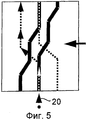
Фиг.5 - фиг.7: четыре возможных процесса регулировки, которые возможны в первом варианте настоящего изобретения, в форме показанной развернутой пазовой направляющей в подъемном профильном элементе согласно фиг.1-4;FIG. 5 to FIG. 7: four possible adjustment processes that are possible in the first embodiment of the present invention, in the form of an expanded groove guide shown in the lifting profile member of FIGS. 1-4;
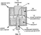
Фиг.9 - фиг.11: продольное сечение электромагнитного регулирующего устройства, которое на конце образует состоящий из нескольких частей толкатель для реализации толкающего блока.Fig.9 - Fig.11: a longitudinal section of an electromagnetic control device, which at the end forms a multi-part pusher for the implementation of the pushing unit.
Фиг.1-4 поясняют, каким образом управляющие пазы (по типу дорожек) проходят в изображенном подъемном профильном элементе (кулачковый элемент); как в этой связи видно, в частности, из фиг.9-11, толкающий блок содержит (образующий узкую область 11 воздействия) внутренний толкатель 10, а также окружающий его, имеющий форму втулки внешний толкатель 12, причем, описанные последующим образом, оба толкателя могут приводиться в действие раздельно независимо друг от друга с помощью электромагнитного управления. При этом внутренний толкатель обеспечивает возможность реализации большей глубины проникновения (с более узким профилем паза, фиг.3, 4), более широкий внешний толкатель (полый толкатель) не может полностью проникнуть на глубину формирующего подобную узкую донную область паза.Figure 1-4 explain how the control grooves (according to the type of tracks) are in the depicted lifting profile element (cam element); as can be seen in this regard, in particular from FIGS. 9-11, the pushing unit comprises (forming a narrow impact region 11) an
Настоящее изобретение предпочтительно обеспечивает возможность реализации с помощью схематически изображенного на фиг.9-11, состоящего из двух частей толкающего блока, в общей сложности одно относительное движение (аксиальное смещение) подъемного профильного элемента между тремя позициями (с тем эффектом, что должен монтироваться единственный, состоящий из нескольких частей, толкающий агрегат и, соответственно, отпадает необходимость в дополнительном аксиальном конструктивном пространстве с соответствующими дополнительными издержками).The present invention preferably makes it possible to implement, with the help of a two-part pushing block schematically shown in FIGS. 9-11, a total of one relative movement (axial displacement) of the lifting profile element between three positions (with the effect that a single, consisting of several parts, the pushing unit and, accordingly, there is no need for additional axial structural space with corresponding additional costs s).
Развертки с фиг.5-8 соответствующих форм пазовых дорожек (управляющих пазов) обозначены при этом жирными черными штрихами или штриховыми участками (то есть широкий паз), а также пунктирные формы пазовых дорожек (узкий паз) при наложении также проходящего углубленно внутри широкого паза узкого паза. Далее, состоящий из двух частей толкатель обозначен черной точкой (фиг.1, фиг.8, а именно активация посредством внутреннего толкателя), а также окружностью или кольцом в качестве символа (фиг.6, фиг.7), в соответствии с имеющим форму втулки полым и, соответственно, внешним толкателем.The reamers shown in FIGS. 5-8 of the corresponding shapes of the groove tracks (control grooves) are indicated with bold black strokes or dashed sections (i.e., a wide groove), as well as the dotted shapes of the groove tracks (narrow groove) when applying a narrow narrow groove deep inside the wide groove groove. Further, the two-part pusher is indicated by a black dot (Fig. 1, Fig. 8, namely activation by an internal pusher), as well as a circle or ring as a symbol (Fig. 6, Fig. 7), in accordance with the shape bushings hollow and, accordingly, an external pusher.
Фиг.5 поясняет прежде всего, как за счет введения выдвинутого внутреннего толкателя 10 в изображенный глубокий паз (стрелка 20 на фиг.5) обеспечивается смещение вправо кулисы вплоть до позиции по фиг.6 (во всех примерах позиция толкателя остается неизменной). В позиции по фиг.6. с целью обратного отвода в исходное положение (среднее положение) внешний толкатель описывал бы обозначенную стрелками 22 широкую пазовую дорожку, так что в этом случае изображенная кулиса перемещается назад из правой позиции в исходное положение (среднее положение).Figure 5 first of all explains how, by introducing the extended
Далее, фиг.7 показывает, как осуществляется левое смещение из средней позиции с помощью внешней втулки; фиг.8 поясняет возврат из левой позиции в исходное положение (среднее положение) с помощью внутреннего толкателя. Форма пазов или дорожек по фиг.5-8 служит в этом отношении для дальнейшего пояснения конструктивного строения подъемного профильного элемента в соответствии с примером выполнения по фиг.1-4.Further, FIG. 7 shows how left displacement is carried out from the middle position using the outer sleeve; Fig.8 explains the return from the left position to its original position (middle position) using the internal pusher. The shape of the grooves or tracks of FIGS. 5-8 serves in this regard to further explain the structural structure of the lifting profile element in accordance with the exemplary embodiment of FIGS. 1-4.
Фиг.9-11 показывают в схематичной форме конструктивную реализацию исполнительного устройства в виде электромагнитного регулирующего устройства с двумя якорями; одним внутренним толкателем (якорем) 10, который для взаимодействия с (стационарным) сердечником 13 содержит постоянный магнит 14, и вторым якорем 12, который переходит в полый толкатель.Figures 9-11 show in schematic form a structural implementation of an actuator in the form of an electromagnetic control device with two anchors; one internal pusher (anchor) 10, which for interaction with the (stationary)
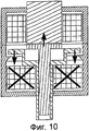
За счет обтекания током катушки II (ссылочная позиция 16) плоский якорь (тем самым полый толкатель 12) перемещается вниз. Постоянный магнит 14 внутреннего толкателя 10 обеспечивает, напротив, что при этом эксплуатационном процессе внутренний толкатель остается на сердечнике 13 и, таким образом, в изображенном на фиг.9, вдвинутом положении.Due to the current flow around coil II (reference position 16), the flat armature (thereby the hollow pusher 12) moves down. The
Фиг.10 показывает выдвинутый таким образом полый толкатель; маркировка «X» одной из катушек символизирует состояние обтекания током.10 shows a hollow pusher extended in this way; marking "X" of one of the coils symbolizes the state of current flow.
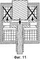
Для выдвижения внутреннего толкателя постоянный магнит (окружающей сердечник 13) катушки I (ссылочная позиция 18) должен выталкиваться (при соответствующем обтекании током катушки I). При этом полый толкатель автоматически (с помощью плоского якоря) вытягивается в плоскости чертежа вверх, так что полый толкатель не может выдвигаться, возникает эксплуатационное состояние по фиг.11.In order to extend the inner follower, the permanent magnet (surrounding the core 13) of coil I (reference position 18) must be pushed out (if the current I is flowing around the coil I). In this case, the hollow pusher is automatically (using a flat anchor) pulled upward in the plane of the drawing, so that the hollow pusher cannot be extended, the operational state of FIG. 11 occurs.
Claims (14)
управление толкающим блоком для взаимодействия с первым управляющим пазом подъемного профильного элемента для аксиального смещения кулачкового вала в первое, аксиально смещенное положение;
управление толкающим блоком для взаимодействия с образованным в подъемном профильном элементе вторым управляющим пазом для смещения кулачкового вала из первой аксиальной позиции смещения в отличную от первой вторую аксиальную позицию смещения;
причем толкающий блок для взаимодействия с первым и вторым управляющими пазами переключают между первой и второй глубиной введения и/или между первой и второй шириной введения, действующей для введения в пазы. 14. A method for adjusting the camshaft of an internal combustion engine using a device according to one of claims 1 to 13, characterized in steps:
control of the pushing unit for interacting with the first control groove of the lifting profile element for axially displacing the cam shaft to a first, axially displaced position;
control of the pushing unit for interacting with the second control groove formed in the lifting profile element for displacing the cam shaft from the first axial displacement position to a second second axial displacement position different from the first;
moreover, the pushing unit for interaction with the first and second control grooves is switched between the first and second depth of introduction and / or between the first and second width of the introduction, valid for insertion into the grooves.
Applications Claiming Priority (3)
| Application Number | Priority Date | Filing Date | Title |
|---|---|---|---|
| DE102007037232A DE102007037232A1 (en) | 2007-08-07 | 2007-08-07 | Device for adjusting the camshaft of an internal combustion engine |
| DE102007037232.0 | 2007-08-07 | ||
| PCT/EP2008/006417 WO2009018991A1 (en) | 2007-08-07 | 2008-08-05 | Device for camshaft adjustment in an internal combustion engine |
Publications (2)
| Publication Number | Publication Date |
|---|---|
| RU2009116263A RU2009116263A (en) | 2010-11-10 |
| RU2476692C2 true RU2476692C2 (en) | 2013-02-27 |
Family
ID=40029144
Family Applications (1)
| Application Number | Title | Priority Date | Filing Date |
|---|---|---|---|
| RU2009116263/06A RU2476692C2 (en) | 2007-08-07 | 2008-08-05 | Device to adjust ice camshaft |
Country Status (7)
| Country | Link |
|---|---|
| US (1) | US8186320B2 (en) |
| EP (2) | EP2636860B1 (en) |
| JP (1) | JP5241836B2 (en) |
| CN (1) | CN101548069B (en) |
| DE (1) | DE102007037232A1 (en) |
| RU (1) | RU2476692C2 (en) |
| WO (1) | WO2009018991A1 (en) |
Cited By (3)
| Publication number | Priority date | Publication date | Assignee | Title |
|---|---|---|---|---|
| RU2756493C2 (en) * | 2017-06-29 | 2021-09-30 | Ман Трак Энд Бас Аг | Adjustable valve drive for internal combustion engine |
| RU2770348C2 (en) * | 2017-07-27 | 2022-04-15 | Ман Трак Энд Бас Аг | Cam mechanism with a tappet, adjusting valve mechanism, vehicle and method for operation of an internal combustion engine |
| RU2778596C2 (en) * | 2018-03-08 | 2022-08-22 | Ман Трак Энд Бас Аг | Adjustable valve drive with system of cams with adjustable position for internal combustion engine |
Families Citing this family (42)
| Publication number | Priority date | Publication date | Assignee | Title |
|---|---|---|---|---|
| DE102007010149A1 (en) * | 2007-03-02 | 2008-09-04 | Audi Ag | Automotive piston engine gas valve timer has right- and left-handed grooves are located immediately alongside and translating into each other |
| DE102007029116A1 (en) | 2007-06-25 | 2009-01-02 | Continental Automotive Gmbh | Method for operating a microcontroller and an execution unit and a microcontroller and an execution unit |
| DE102008029349A1 (en) * | 2008-06-20 | 2009-12-24 | Daimler Ag | Valve drive device |
| DE102008029325A1 (en) * | 2008-06-20 | 2009-12-24 | Daimler Ag | Valve drive device |
| DE102008060167B4 (en) | 2008-11-27 | 2021-05-27 | Dr. Ing. H.C. F. Porsche Aktiengesellschaft | Valve train of an internal combustion engine |
| DE102008060170A1 (en) | 2008-11-27 | 2010-06-02 | Dr.Ing.H.C.F.Porsche Aktiengesellschaft | Valve gear of an internal combustion engine |
| DE102009009080A1 (en) * | 2009-02-14 | 2010-08-19 | Schaeffler Technologies Gmbh & Co. Kg | Valve gear of an internal combustion engine |
| DE102010013216B4 (en) * | 2009-04-04 | 2022-04-28 | Schaeffler Technologies AG & Co. KG | Valve train of an internal combustion engine |
| DE202009011804U1 (en) * | 2009-09-01 | 2011-01-13 | Eto Magnetic Gmbh | Device for adjusting the camshaft of an internal combustion engine |
| DE102009056609A1 (en) * | 2009-12-02 | 2011-06-09 | Schaeffler Technologies Gmbh & Co. Kg | Electromagnetic actuator |
| JP5510095B2 (en) * | 2010-06-15 | 2014-06-04 | トヨタ自動車株式会社 | Variable valve operating device for internal combustion engine |
| DE102010053359A1 (en) * | 2010-12-03 | 2012-06-06 | Schaeffler Technologies Gmbh & Co. Kg | Sliding cam system with sliding grooves and locks |
| DE102012204621A1 (en) * | 2012-03-22 | 2013-09-26 | Schaeffler Technologies AG & Co. KG | Cam piece for a variable sliding cam valve drive |
| JP6003185B2 (en) * | 2012-04-25 | 2016-10-05 | マツダ株式会社 | Engine cam shifting device |
| DE102012210212B4 (en) * | 2012-06-18 | 2014-12-11 | Schaeffler Technologies Gmbh & Co. Kg | Sliding cam system of a reciprocating internal combustion engine with X-shaped sliding grooves and switches |
| DE102012106824A1 (en) * | 2012-07-26 | 2014-01-30 | Eto Magnetic Gmbh | Electromagnetic actuator |
| DE102012222113A1 (en) * | 2012-12-04 | 2014-06-18 | Schaeffler Technologies Gmbh & Co. Kg | Valve train of an internal combustion engine |
| JP6056485B2 (en) * | 2013-01-11 | 2017-01-11 | スズキ株式会社 | Variable valve operating device for internal combustion engine |
| DE102013201827A1 (en) * | 2013-02-05 | 2014-08-07 | Schaeffler Technologies Gmbh & Co. Kg | Diagnostic procedure of a valve train actuator |
| DE102013202132A1 (en) * | 2013-02-08 | 2014-08-14 | Schaeffler Technologies Gmbh & Co. Kg | Push cam actuator with seal |
| DE102013102241A1 (en) | 2013-03-06 | 2014-09-11 | Kendrion (Villingen) Gmbh | Electromagnetic actuator, in particular for the camshaft adjustment of an internal combustion engine |
| KR101448778B1 (en) * | 2013-03-08 | 2014-10-13 | 현대자동차 주식회사 | Mutiple variable valve lift appratus |
| CN103306776B (en) * | 2013-06-28 | 2015-09-09 | 长城汽车股份有限公司 | For the variable air valve lift apparatus of motor, motor and vehicle |
| CN103437894B (en) * | 2013-08-13 | 2017-03-22 | 奇瑞汽车股份有限公司 | Control device and method for cylinder deactivation of engine |
| DE102013221244A1 (en) | 2013-10-21 | 2015-04-23 | Volkswagen Aktiengesellschaft | Device for adjusting the camshaft of an internal combustion engine |
| DE102014217167A1 (en) | 2014-08-28 | 2016-03-17 | Schaeffler Technologies AG & Co. KG | Actuator device in a modular design |
| DE102014217755A1 (en) | 2014-09-05 | 2016-03-10 | Schaeffler Technologies AG & Co. KG | Actuator device for sliding cam systems |
| DE102014220266A1 (en) | 2014-10-07 | 2016-04-07 | Schaeffler Technologies AG & Co. KG | Actuator device with sleeve support on an internal combustion engine |
| US9583249B2 (en) | 2014-10-31 | 2017-02-28 | Husco Automotive Holdings Llc | Methods and systems for push pin actuator |
| DE102014017036B3 (en) * | 2014-11-18 | 2016-03-24 | Audi Ag | Valve train for an internal combustion engine and corresponding internal combustion engine |
| DE102015103761A1 (en) | 2015-03-13 | 2016-09-29 | Kendrion (Villingen) Gmbh | Control element for the axial displacement of a camshaft slidably mounted along a camshaft axis |
| CN108138609B (en) | 2015-11-06 | 2022-01-14 | 博格华纳公司 | Valve operating system providing variable valve lift and/or variable valve timing |
| DE102016005454A1 (en) * | 2016-05-03 | 2017-11-09 | Daimler Ag | Valve train device, in particular for an internal combustion engine |
| CN105850316A (en) * | 2016-06-01 | 2016-08-17 | 黑龙江省农垦科学院农业工程研究所 | Combined cam for controlling swing of planting arm |
| CN106121764A (en) * | 2016-07-18 | 2016-11-16 | 杰锋汽车动力系统股份有限公司 | A kind of camshaft adjuster for variable valve lift system |
| US20180094554A1 (en) * | 2016-10-05 | 2018-04-05 | GM Global Technology Operations LLC | Variable camshaft |
| DE102016220612A1 (en) * | 2016-10-20 | 2018-04-26 | Mahle International Gmbh | Valve train for an internal combustion engine |
| DE102016124851A1 (en) * | 2016-12-19 | 2018-06-21 | Volkswagen Aktiengesellschaft | Valve gear of an internal combustion engine |
| JP6438987B2 (en) * | 2017-02-17 | 2018-12-19 | 本田技研工業株式会社 | Variable valve gear |
| EP3669068B1 (en) | 2017-08-17 | 2022-11-23 | Wärtsilä Finland Oy | A camshaft assembly for an internal combustion piston engine and a method of converting an internal combustion piston engine to run in at least two operational modes |
| DE102017121947A1 (en) * | 2017-09-21 | 2019-03-21 | Kendrion (Villingen) Gmbh | Actuator with a sealed guide cylinder |
| DE102018110705A1 (en) | 2018-05-04 | 2019-11-07 | Man Truck & Bus Se | Variable valve train |
Citations (6)
| Publication number | Priority date | Publication date | Assignee | Title |
|---|---|---|---|---|
| JPS5244314A (en) * | 1975-10-06 | 1977-04-07 | Mitsubishi Motors Corp | Variable valve-timing device |
| RU2068102C1 (en) * | 1990-10-01 | 1996-10-20 | Бритиш Текнолоджи груп Лтд. | Driving joint |
| DE19611641C1 (en) * | 1996-03-25 | 1997-06-05 | Porsche Ag | Valve operating cam drive for combustion engines |
| DE10148177A1 (en) * | 2001-09-28 | 2003-04-17 | Ina Schaeffler Kg | Valve drive with valve stroke reversal for gas exchange valves of 4-stroke IC engines has slide grooves extending across each other due to location at small relative distance, to reduce axial space requirement |
| DE10148178A1 (en) * | 2001-09-28 | 2003-04-17 | Ina Schaeffler Kg | Method for reduction of fuel consumption and exhaust emissions of 4-stroke IC engines with at least one cylinder being operated in 8-stroke method with three high-pressure loops suitable for ignition |
| DE102005003079A1 (en) * | 2005-01-22 | 2006-08-03 | Audi Ag | Internal combustion engine has housing at which for each actuator, one mounting surface is arranged such that in each mounting surface, lubricant bore is arranged |
Family Cites Families (14)
| Publication number | Priority date | Publication date | Assignee | Title |
|---|---|---|---|---|
| GB191210648A (en) * | 1911-07-24 | 1912-10-24 | Juhana Kylliainen | Improvements in or relating to Reversing Gear for Internal Combustion Engines. |
| GB191410648A (en) | 1914-04-30 | 1914-11-19 | Robert William Richards | Improvements in the Lubrication of Internal Combustion Engines. |
| JPS60263762A (en) * | 1984-06-13 | 1985-12-27 | Japan Tobacco Inc | Driving device for reciprocating shaft |
| JPS62184118U (en) * | 1986-05-16 | 1987-11-21 | ||
| JPH0450572Y2 (en) * | 1987-12-25 | 1992-11-30 | ||
| AT408127B (en) * | 1992-07-13 | 2001-09-25 | Avl Verbrennungskraft Messtech | Internal combustion engine with at least one camshaft that can be axially displaced by an adjusting device |
| JP4259017B2 (en) * | 2001-05-31 | 2009-04-30 | トヨタ自動車株式会社 | Variable valve operating device for internal combustion engine |
| DE102004011586A1 (en) * | 2003-03-21 | 2004-10-07 | Audi Ag | Valve gear for internal combustion engine has facility whereby in first and second axial positions of cam carrier first and second stop faces fixed on cam carrier bear against respective first and second stop faces fixed on cylinder head |
| EP1503048B1 (en) * | 2003-07-19 | 2008-10-08 | Dr. Ing. h.c. F. Porsche Aktiengesellschaft | Valve drive for an internal combustion engine |
| DE102004008670B4 (en) * | 2004-02-21 | 2013-04-11 | Schaeffler Technologies AG & Co. KG | Valve drive with cam switching for the gas exchange valves of a 4-stroke internal combustion engine |
| DE102004037198A1 (en) * | 2004-07-30 | 2006-03-23 | Ina-Schaeffler Kg | Valve gear of an internal combustion engine |
| DE102007010149A1 (en) * | 2007-03-02 | 2008-09-04 | Audi Ag | Automotive piston engine gas valve timer has right- and left-handed grooves are located immediately alongside and translating into each other |
| DE102008060167B4 (en) * | 2008-11-27 | 2021-05-27 | Dr. Ing. H.C. F. Porsche Aktiengesellschaft | Valve train of an internal combustion engine |
| DE202009011804U1 (en) * | 2009-09-01 | 2011-01-13 | Eto Magnetic Gmbh | Device for adjusting the camshaft of an internal combustion engine |
-
2007
- 2007-08-07 DE DE102007037232A patent/DE102007037232A1/en not_active Withdrawn
-
2008
- 2008-08-05 EP EP13171054.3A patent/EP2636860B1/en active Active
- 2008-08-05 US US12/514,510 patent/US8186320B2/en active Active
- 2008-08-05 RU RU2009116263/06A patent/RU2476692C2/en active
- 2008-08-05 JP JP2010519371A patent/JP5241836B2/en active Active
- 2008-08-05 CN CN200880000894.7A patent/CN101548069B/en active Active
- 2008-08-05 EP EP08785345.3A patent/EP2082120B1/en active Active
- 2008-08-05 WO PCT/EP2008/006417 patent/WO2009018991A1/en active Application Filing
Patent Citations (6)
| Publication number | Priority date | Publication date | Assignee | Title |
|---|---|---|---|---|
| JPS5244314A (en) * | 1975-10-06 | 1977-04-07 | Mitsubishi Motors Corp | Variable valve-timing device |
| RU2068102C1 (en) * | 1990-10-01 | 1996-10-20 | Бритиш Текнолоджи груп Лтд. | Driving joint |
| DE19611641C1 (en) * | 1996-03-25 | 1997-06-05 | Porsche Ag | Valve operating cam drive for combustion engines |
| DE10148177A1 (en) * | 2001-09-28 | 2003-04-17 | Ina Schaeffler Kg | Valve drive with valve stroke reversal for gas exchange valves of 4-stroke IC engines has slide grooves extending across each other due to location at small relative distance, to reduce axial space requirement |
| DE10148178A1 (en) * | 2001-09-28 | 2003-04-17 | Ina Schaeffler Kg | Method for reduction of fuel consumption and exhaust emissions of 4-stroke IC engines with at least one cylinder being operated in 8-stroke method with three high-pressure loops suitable for ignition |
| DE102005003079A1 (en) * | 2005-01-22 | 2006-08-03 | Audi Ag | Internal combustion engine has housing at which for each actuator, one mounting surface is arranged such that in each mounting surface, lubricant bore is arranged |
Cited By (5)
| Publication number | Priority date | Publication date | Assignee | Title |
|---|---|---|---|---|
| RU2756493C2 (en) * | 2017-06-29 | 2021-09-30 | Ман Трак Энд Бас Аг | Adjustable valve drive for internal combustion engine |
| RU2770348C2 (en) * | 2017-07-27 | 2022-04-15 | Ман Трак Энд Бас Аг | Cam mechanism with a tappet, adjusting valve mechanism, vehicle and method for operation of an internal combustion engine |
| RU2778596C2 (en) * | 2018-03-08 | 2022-08-22 | Ман Трак Энд Бас Аг | Adjustable valve drive with system of cams with adjustable position for internal combustion engine |
| RU2779012C2 (en) * | 2018-05-04 | 2022-08-30 | МАН Трак энд Бас СЕ | Adjustable valve drive |
| RU2785248C2 (en) * | 2019-04-30 | 2022-12-05 | МАН Трак энд Бас СЕ | Adjustable valve drive and vehicle with specified drive |
Also Published As
| Publication number | Publication date |
|---|---|
| JP2010535964A (en) | 2010-11-25 |
| US8186320B2 (en) | 2012-05-29 |
| RU2009116263A (en) | 2010-11-10 |
| CN101548069B (en) | 2014-01-22 |
| EP2082120A1 (en) | 2009-07-29 |
| EP2082120B1 (en) | 2013-10-09 |
| US20100126445A1 (en) | 2010-05-27 |
| WO2009018991A1 (en) | 2009-02-12 |
| JP5241836B2 (en) | 2013-07-17 |
| EP2636860B1 (en) | 2014-12-17 |
| EP2636860A1 (en) | 2013-09-11 |
| CN101548069A (en) | 2009-09-30 |
| DE102007037232A1 (en) | 2009-02-12 |
Similar Documents
| Publication | Publication Date | Title |
|---|---|---|
| RU2476692C2 (en) | Device to adjust ice camshaft | |
| JP2010535964A5 (en) | ||
| CN102066699B (en) | Valve train device | |
| US8474424B2 (en) | Valve drive train device | |
| KR101378623B1 (en) | Internal combustion engine and valve drive for an internal combustion engine | |
| US8707917B2 (en) | Device for adjusting a camshaft of an internal combustion engine | |
| JP5746204B2 (en) | Electromagnetic actuator | |
| KR101512871B1 (en) | Electromagnetic actuating unit of a solenoid valve, and method for the prodution of such an actuating unit | |
| EP3334915B1 (en) | Reciprocating piston engine, in particular internal combustion engine | |
| CN102171420A (en) | Valve operating mechanism | |
| US10539050B2 (en) | Valve drive for an internal combustion engine | |
| EP2929550B1 (en) | Electromagnetic actuating apparatus | |
| CN108474276B (en) | Cam switching device and control method of cam switching device | |
| DE60303334T2 (en) | Stirling engine | |
| US9082574B2 (en) | Starter relay for a starting apparatus | |
| CN111794821A (en) | Valve mechanism for internal combustion engine | |
| CN108691593B (en) | Valve drive device for internal combustion engine | |
| KR20190113834A (en) | Electromagnetic Linear Actuator | |
| CN111033030B (en) | Camshaft assembly for an internal combustion piston engine and method for converting an internal combustion piston engine to operate in at least two operating modes | |
| JP6003185B2 (en) | Engine cam shifting device |