RU2449749C2 - Disposable cassette for staples containing stop with tissue fixer for application with surgical cutting and fixing apparatus and module system of end effector for said apparatus - Google Patents
Disposable cassette for staples containing stop with tissue fixer for application with surgical cutting and fixing apparatus and module system of end effector for said apparatus Download PDFInfo
- Publication number
- RU2449749C2 RU2449749C2 RU2007103553/14A RU2007103553A RU2449749C2 RU 2449749 C2 RU2449749 C2 RU 2449749C2 RU 2007103553/14 A RU2007103553/14 A RU 2007103553/14A RU 2007103553 A RU2007103553 A RU 2007103553A RU 2449749 C2 RU2449749 C2 RU 2449749C2
- Authority
- RU
- Russia
- Prior art keywords
- brackets
- disposable
- cassette
- stop
- end effector
- Prior art date
Links
Images


Classifications
-
- A—HUMAN NECESSITIES
- A61—MEDICAL OR VETERINARY SCIENCE; HYGIENE
- A61B—DIAGNOSIS; SURGERY; IDENTIFICATION
- A61B17/00—Surgical instruments, devices or methods, e.g. tourniquets
- A61B17/068—Surgical staplers, e.g. containing multiple staples or clamps
- A61B17/072—Surgical staplers, e.g. containing multiple staples or clamps for applying a row of staples in a single action, e.g. the staples being applied simultaneously
- A61B17/07207—Surgical staplers, e.g. containing multiple staples or clamps for applying a row of staples in a single action, e.g. the staples being applied simultaneously the staples being applied sequentially
-
- A—HUMAN NECESSITIES
- A61—MEDICAL OR VETERINARY SCIENCE; HYGIENE
- A61B—DIAGNOSIS; SURGERY; IDENTIFICATION
- A61B17/00—Surgical instruments, devices or methods, e.g. tourniquets
- A61B17/04—Surgical instruments, devices or methods, e.g. tourniquets for suturing wounds; Holders or packages for needles or suture materials
-
- A—HUMAN NECESSITIES
- A61—MEDICAL OR VETERINARY SCIENCE; HYGIENE
- A61B—DIAGNOSIS; SURGERY; IDENTIFICATION
- A61B17/00—Surgical instruments, devices or methods, e.g. tourniquets
- A61B17/064—Surgical staples, i.e. penetrating the tissue
-
- A—HUMAN NECESSITIES
- A61—MEDICAL OR VETERINARY SCIENCE; HYGIENE
- A61B—DIAGNOSIS; SURGERY; IDENTIFICATION
- A61B17/00—Surgical instruments, devices or methods, e.g. tourniquets
- A61B2017/0023—Surgical instruments, devices or methods, e.g. tourniquets disposable
-
- A—HUMAN NECESSITIES
- A61—MEDICAL OR VETERINARY SCIENCE; HYGIENE
- A61B—DIAGNOSIS; SURGERY; IDENTIFICATION
- A61B17/00—Surgical instruments, devices or methods, e.g. tourniquets
- A61B17/068—Surgical staplers, e.g. containing multiple staples or clamps
- A61B17/072—Surgical staplers, e.g. containing multiple staples or clamps for applying a row of staples in a single action, e.g. the staples being applied simultaneously
- A61B2017/07214—Stapler heads
- A61B2017/07285—Stapler heads characterised by its cutter
-
- A—HUMAN NECESSITIES
- A61—MEDICAL OR VETERINARY SCIENCE; HYGIENE
- A61B—DIAGNOSIS; SURGERY; IDENTIFICATION
- A61B17/00—Surgical instruments, devices or methods, e.g. tourniquets
- A61B17/28—Surgical forceps
- A61B17/2812—Surgical forceps with a single pivotal connection
- A61B17/282—Jaws
- A61B2017/2825—Inserts of different material in jaws
Abstract
Description
ПЕРЕКРЕСТНАЯ ССЫЛКА НА РОДСТВЕННЫЕ ЗАЯВКИCROSS REFERENCE TO RELATED APPLICATIONS
Настоящая заявка связана с ниже перечисленными заявками на патенты США, которые целиком включены в настоящую заявку путем отсылки:This application is associated with the following US patent applications, which are incorporated herein by reference in their entirety:
MOTOR-DRIVEN SURGICAL CUTTING AND FASTENING INSTRUMENT WITH USER FEEDBACK SYSTEMMOTOR-DRIVEN SURGICAL CUTTING AND FASTENING INSTRUMENT WITH USER FEEDBACK SYSTEM
Изобретатели: Frederick E. Shelton, IV, John Ouwerkerk and Jerome R. Morgan (K&LNG 0505I9/END5687USNP)Inventors: Frederick E. Shelton, IV, John Ouwerkerk and Jerome R. Morgan (K & LNG 0505I9 / END5687USNP)
MOTOR-DRIVEN SURGICAL CUTTING AND FASTENING INSTRUMENT WITH LOADING FORCE FEEDBACKMOTOR-DRIVEN SURGICAL CUTTING AND FASTENING INSTRUMENT WITH LOADING FORCE FEEDBACK
Изобретатели: Frederick E. Shelton, IV, John N. Ouwerkerk, Jerome R. Morgan, and Jeffrey S. Swayze (K&LNG 050516/END5692USNP)Inventors: Frederick E. Shelton, IV, John N. Ouwerkerk, Jerome R. Morgan, and Jeffrey S. Swayze (K & LNG 050516 / END5692USNP)
MOTOR-DRIVEN SURGICAL CUTTING AND FASTENING INSTRUMENT WITH TACTILE POSITION FEEDBACKMOTOR-DRIVEN SURGICAL CUTTING AND FASTENING INSTRUMENT WITH TACTILE POSITION FEEDBACK
Изобретатели: Frederick E. Shelton, IV, John N. Ouwerkerk, Jerome R. Morgan, and Jeffrey S. Swayze (K&LNG 050515/END5693USNP)Inventors: Frederick E. Shelton, IV, John N. Ouwerkerk, Jerome R. Morgan, and Jeffrey S. Swayze (K & LNG 050515 / END5693USNP)
MOTOR-DRIVEN SURGICAL CUTTING AND FASTENING INSTRUMENT WITH ADAPTIVE USER FEEDBACKMOTOR-DRIVEN SURGICAL CUTTING AND FASTENING INSTRUMENT WITH ADAPTIVE USER FEEDBACK
Изобретатели: Frederick E. Shelton, IV, John N. Ouwerkerk, and Jerome R. Morgan (K&LNG 050513/END5694USNP)Inventors: Frederick E. Shelton, IV, John N. Ouwerkerk, and Jerome R. Morgan (K & LNG 050513 / END5694USNP)
MOTOR-DRIVEN SURGICAL CUTTING AND FASTENING INSTRUMENT WITH ARTICULATABLE END EFFECTORMOTOR-DRIVEN SURGICAL CUTTING AND FASTENING INSTRUMENT WITH ARTICULATABLE END EFFECTOR
Изобретатели: Frederick E. Shelton, IV and Christoph L. Gillum (K&LNG 050692/END5769USNP)Inventors: Frederick E. Shelton, IV and Christoph L. Gillum (K & LNG 050692 / END5769USNP)
MOTOR-DRIVEN SURGICAL CUTTING AND FASTENING INSTRUMENT WITH MECHANICAL CLOSURE SYSTEMMOTOR-DRIVEN SURGICAL CUTTING AND FASTENING INSTRUMENT WITH MECHANICAL CLOSURE SYSTEM
Изобретатели: Frederick E. Shelton, IV and Christoph L. Gillum (K&LNG 050693/END5770USNP)Inventors: Frederick E. Shelton, IV and Christoph L. Gillum (K & LNG 050693 / END5770USNP)
SURGICAL CUTTING AND FASTENING INSTRUMENT WITH CLOSURE TRIGGER LOCKING MECHANISMSURGICAL CUTTING AND FASTENING INSTRUMENT WITH CLOSURE TRIGGER LOCKING MECHANISM
Изобретатели: Frederick E. Shelton, IV and Kevin R. Doll (K&LNG 050694/END5771USNP)Inventors: Frederick E. Shelton, IV and Kevin R. Doll (K & LNG 050694 / END5771USNP)
GEARING SELECTOR FOR A POWERED SURGICAL CUTTING AND FASTENING STAPLING INSTRUMENTGEARING SELECTOR FOR A POWERED SURGICAL CUTTING AND FASTENING STAPLING INSTRUMENT
Изобретатели: Frederick E. Shelton, IV, Jeffrey S, Swayze, Eugene L. Timperman (K&LNG 050697/END5772USNP)Inventors: Frederick E. Shelton, IV, Jeffrey S, Swayze, Eugene L. Timperman (K & LNG 050697 / END5772USNP)
SURGICAL INSTRUMENT HAVING RECORDING CAPABILITIESSURGICAL INSTRUMENT HAVING RECORDING CAPABILITIES
Изобретатели: Frederick E. Shelton, IV, John N. Ouwerkerk, and Eugene L. Timperman (K&LNG 050698/END5773USNP)Inventors: Frederick E. Shelton, IV, John N. Ouwerkerk, and Eugene L. Timperman (K & LNG 050698 / END5773USNP)
SURGICAL INSTRUMENT HAVING A REMOVABLE BATTERYSURGICAL INSTRUMENT HAVING A REMOVABLE BATTERY
Изобретатели: Frederick E. Shelton, IV, Kevin R. Doll, Jeffrey S. Swayze and Eugene Timperman (K&LNG 050699/END5774USNP)Inventors: Frederick E. Shelton, IV, Kevin R. Doll, Jeffrey S. Swayze and Eugene Timperman (K & LNG 050699 / END5774USNP)
ELECTRONIC LOCKOUTS AND SURGICAL INSTRUMENT INCLUDING SAMEELECTRONIC LOCKOUTS AND SURGICAL INSTRUMENT INCLUDING SAME
Изобретатели: Jeffrey S. Swayze, Frederick E. Shelton, IV, Kevin R. Doll (K&LNG 050700/END5775USNP)Inventors: Jeffrey S. Swayze, Frederick E. Shelton, IV, Kevin R. Doll (K & LNG 050700 / END5775USNP)
ENDOSCOPIC SURGICAL INSTRUMENT WITH A HANDLE THAT CAN ARTICULATE WITH RESPECT TO THE SHAFTENDOSCOPIC SURGICAL INSTRUMENT WITH A HANDLE THAT CAN ARTICULATE WITH RESPECT TO THE SHAFT
Изобретатели: Frederick E. Shelton, IV, Jeffrey S. Swayze, Mark S. Ortiz, and Leslie M. Fugikawa (K&LNG 050701 END5776USNP)Inventors: Frederick E. Shelton, IV, Jeffrey S. Swayze, Mark S. Ortiz, and Leslie M. Fugikawa (K & LNG 050701 END5776USNP)
ELECTRO-MECHANICAL SURGICAL CUTTING AND FASTENING INSTRUMENT HAVING A ROTARY FIRING AND CLOSURE SYSTEM WITH PARALLEL CLOSURE AND ANVIL ALIGNMENT COMPONENTSELECTRO-MECHANICAL SURGICAL CUTTING AND FASTENING INSTRUMENT HAVING A ROTARY FIRING AND CLOSURE SYSTEM WITH PARALLEL CLOSURE AND ANVIL ALIGNMENT COMPONENTS
Изобретатели: Frederick E. Shelton, IV, Stephen J. Balek and Eugene L. Timperman (K&LNG 050702/END5777USNP)Inventors: Frederick E. Shelton, IV, Stephen J. Balek and Eugene L. Timperman (K & LNG 050702 / END5777USNP)
SURGICAL INSTRUMENT HAVING A FEEDBACK SYSTEMSURGICAL INSTRUMENT HAVING A FEEDBACK SYSTEM
Изобретатели: Frederick E. Shelton, IV, Jerome R. Morgan, Kevin R. Doll, Jeffrey S. Swayze and Eugene Timperman (K&LNG 050705/END5780USNP)Inventors: Frederick E. Shelton, IV, Jerome R. Morgan, Kevin R. Doll, Jeffrey S. Swayze and Eugene Timperman (K & LNG 050705 / END5780USNP)
УРОВЕНЬ ТЕХНИКИBACKGROUND
Настоящее изобретение относится, в общем, к хирургическим аппаратам и, в частности, к хирургическим отрезным и фиксирующим аппаратам.The present invention relates, in General, to surgical devices and, in particular, to surgical cutting and fixing devices.
Эндоскопическим хирургическим аппаратам часто отдают предпочтение перед традиционными открытыми хирургическими устройствами, поскольку при меньшем рассечении обычно меньше время послеоперационного восстановления и риск осложнений. Как правило, данные эндоскопические хирургические аппараты содержат «концевой эффектор», узел рукоятки и удлиненный стержень, который продолжается между концевым эффектором и узлом рукоятки. Концевой эффектор является участком аппарата (например, эндоскопического режущего инструмента, захвата, режущего приспособления, сшивающих скобками аппаратов, приспособления для наложения зажимов, устройства доступа, устройства для доставки лекарства генной терапии к месту действия и энергетического устройства, использующего ультразвук, высокую частоту (RF), лазер и т.д.), выполненным с возможностью взаимодействия с тканью множеством способов для получения диагностического или терапевтического результата.Endoscopic surgical devices are often preferred over traditional open surgical devices, since with a smaller incision, postoperative recovery time and risk of complications are usually less. Typically, these endoscopic surgical devices contain an “end effector”, a handle assembly and an elongated shaft that extends between the end effector and the handle assembly. The end effector is a portion of the apparatus (for example, an endoscopic cutting tool, grab, cutting device, stapling devices, clamping device, access device, gene therapy drug delivery device and ultrasound-powered energy device, high frequency (RF) , laser, etc.) configured to interact with tissue in a variety of ways to obtain a diagnostic or therapeutic result.
Концевой эффектор и участок стержня выполнены с размером для введения через троакар, установленный в пациенте. Участок удлиненного стержня позволяет вводить концевой эффектор на заданную глубину, а также способствует некоторому повороту концевого эффектора для его установки внутри пациента. При продуманном размещении троакара и применении захватов, например, через другой троакар часто достаточно упомянутого размаха позиционирования. Хирургические сшивающие скобками и отрезные аппараты, например, такие, которые описаны в патенте США № 5,465,895, являются примерами эндоскопического хирургического аппарата, который успешно позиционирует концевой эффектор посредством введения и поворота.The end effector and the portion of the rod are made with the size for introduction through the trocar installed in the patient. A section of the elongated rod allows you to enter the end effector to a given depth, and also contributes to some rotation of the end effector for installation inside the patient. With the careful placement of the trocar and the use of grips, for example, through another trocar, the aforementioned range of positioning is often sufficient. Surgical staples and cut-offs, for example, those described in US Pat. No. 5,465,895, are examples of an endoscopic surgical apparatus that successfully positions the end effector by insertion and rotation.
Изготовителями различных медицинских компонентов применялись в прошлом два основных подхода к конструированию для уменьшения общей стоимости данных эндоскопических хирургических аппаратов. Хотя оба подхода успешно решали, по меньшей мере, некоторые потребности пользователя, ни одна из попыток не обеспечила полного удовлетворения всех упомянутых потребностей.In the past, manufacturers of various medical components have used two main design approaches to reduce the total cost of these endoscopic surgical devices. Although both approaches successfully solved at least some of the user's needs, none of the attempts provided a complete satisfaction of all the mentioned needs.
Например, первый подход к конструированию относится к использованию одноразового концевого эффектора для каждой операции прошивки/отрезания. Такие концевые эффекторы изготавливались из относительно мягких компонентов, которыми прошивку/отрезание можно выполнить лишь один раз до того, как потребуется новый концевой эффектор, поскольку компоненты концевого эффектора заметно деформируются после каждой операции прошивки/отрезания. В концевом эффекторе данного типа применен конструктивный элемент вида «I-образной поперечины» на ноже для предотвращения отклонения упора от кассеты во время прошивки/отрезания. Поскольку I-образная поперечина двигается по сравнительно нежесткому компоненту упора, I-образная поперечина деформирует участок упора, расположенный непосредственно под конструктивным элементом вида I-образной поперечины. Такое сочетание факторов обеспечивает возможность совершенствования формы скобок при уменьшении усилий, необходимых для приведения в действие устройства, поскольку I-образная поперечина всего лишь подтягивает материал упора вниз в правильное положение относительно кассеты, в котором требуется формировать скобку в любой данный момент времени.For example, the first design approach relates to the use of a disposable end effector for each flashing / cutting operation. Such end effectors were made of relatively soft components, which can be flashed / cut only once before a new end effect is needed, since the end effect components are noticeably deformed after each flashing / cutting operation. In the end effector of this type, a structural element of the “I-shaped cross-member” type on the knife is used to prevent deviation of the stop from the cartridge during flashing / cutting. Since the I-shaped cross member moves along the relatively non-rigid component of the stop, the I-shaped cross member deforms the stop portion located directly under the structural element of the form of the I-shaped cross member. This combination of factors makes it possible to improve the shape of the brackets while reducing the effort required to actuate the device, since the I-shaped cross member merely pulls the stop material down to the correct position relative to the cassette in which it is necessary to form the bracket at any given time.
Хотя данный подход совершенствует форму скобок и уменьшает усилие, необходимое для отрезания ткани и постановку скобок, но характеризуется рядом недостатков. Во-первых, удаление хирургом всего упора, желоба и кассеты после каждой операции прошивки/отрезания значительно увеличивает производственные затраты. Во-вторых, устройство часто не надежно зажимает намеченную ткань из-за сочетания относительно мягких компонентов концевого эффектора и способа, которым упор фактически сжимают на ткани. Третья проблема заключается в том, что относительно мягкие компоненты концевого эффектора можно надежно использовать всего один раз для прошивки/отрезания ткани средней толщины, и компоненты не будут работать на очень толстых тканях.Although this approach improves the shape of the brackets and reduces the effort required to cut the fabric and staples, it is characterized by a number of disadvantages. Firstly, the removal by the surgeon of all the stop, gutter and cassette after each flashing / cutting operation significantly increases production costs. Secondly, the device often does not reliably clamp the intended fabric due to the combination of the relatively soft components of the end effector and the manner in which the emphasis is actually compressed on the fabric. The third problem is that the relatively soft components of the end effector can be reliably used only once for sewing / cutting tissue of medium thickness, and the components will not work on very thick fabrics.
Второй основной подход к конструированию, применявшийся в прошлом, заключается в изготовлении намного более прочных компонентов концевого эффектора, которые можно использовать для нескольких операций прошивки/отрезания. При данном подходе заменяют только кассетный узел после каждой операции прошивки/отрезания. Так как компоненты концевого эффектора должны выдерживать нагрузки нескольких операций прошивки/отрезания, данные компоненты специально конструируют так, чтобы они не деформировались после каждой операции прошивки/отрезания. Описанное конструктивное решение использует другой набор конструктивных элементов на ноже для выдерживания упора в таком положении относительно кассеты во время постановки скобок, чтобы совершенствовать форму скобки. Сочетание более жестких компонентов концевого эффектора и отличающегося зажимного механизма позволяет устройству данного типа надежно прилагать большие сжимающие нагрузки, и поэтому хирург может легко манипулировать требуемой тканью. Более жесткие компоненты позволяют также надежно применять концевой эффектор на относительно толстых образцах ткани.The second main design approach used in the past is to make much stronger end effector components that can be used for several flashing / cutting operations. With this approach, only the cassette assembly is replaced after each flashing / cutting operation. Since the components of the end effector must withstand the loads of several flashing / cutting operations, these components are specially designed so that they do not deform after each flashing / cutting operation. The described structural solution uses a different set of structural elements on the knife to maintain the emphasis in this position relative to the cassette during setting brackets to improve the shape of the brackets. The combination of more rigid components of the end effector and a different clamping mechanism allows this type of device to reliably apply large compressive loads, and therefore the surgeon can easily manipulate the desired tissue. The stiffer components also allow the end effector to be reliably applied to relatively thick tissue samples.
Однако один недостаток данного подхода заключается в том, что теперь от конструктивных элементов на ноже, которые предотвращают отклонение упора от кассеты, требуется подтягивание очень жесткого компонента упора вниз к кассете. Поэтому нож должен подтягивать вниз к кассете всю поперечину, которая имеет такую же длину, как весь ряд скобок, вместо подтягивания вниз упора только в ограниченной области, как в вышеописанном устройстве. Поэтому, при данном подходе, обычно требуется развитие больших усилий срабатывания вследствие повышенных нагрузок лобового сопротивления упора на нож.However, one drawback of this approach is that now from the structural elements on the knife, which prevent the emphasis from deviating from the cartridge, it is necessary to pull the very rigid component of the emphasis down to the cartridge. Therefore, the knife should pull down to the cassette the entire cross member, which has the same length as the entire row of brackets, instead of pulling down the stop only in a limited area, as in the above device. Therefore, with this approach, the development of large actuation forces is usually required due to the increased loads of the frontal resistance of the stop on the knife.
Следовательно, существует потребность в конструкции концевого эффектора для хирургического отрезного и фиксирующего аппарата, который устраняет вышеупомянутые проблемы посредством сохранения таких же показателей качества формы скобок, характеристик зажима и способности многократной установки скобок в толстой ткани, при снижении величины усилия, необходимого для установки скобок и срабатывания ножа.Therefore, there is a need for an end effector design for a surgical cutting and fixing apparatus that eliminates the aforementioned problems by maintaining the same quality indicators for the shape of the brackets, clamping characteristics and the ability to repeatedly install the brackets in thick tissue, while reducing the amount of force required to set the brackets and operate a knife.
Кроме того, существует потребность в системе концевого эффектора, которую можно использовать с кассетами для скобок, которые имеют одинаковую длину, но разные длины рядов скобок.In addition, there is a need for an end effector system that can be used with cassette brackets that have the same length but different lengths of rows of brackets.
СУЩНОСТЬ ИЗОБРЕТЕНИЯSUMMARY OF THE INVENTION
В соответствии с одним общим аспектом настоящее изобретение относится к одноразовой кассете для скобок для хирургического отрезного и фиксирующего аппарата, которая содержит корпус кассеты, который служит опорой для установки в нем с возможностью функционирования множества скобок. Различные одноразовые кассеты для скобок по настоящему изобретению дополнительно содержат одноразовый элемент упора, который можно устанавливать относительно корпуса кассеты так, что элемент упора может перемещаться между сомкнутым положением, в котором нижняя поверхность элемента упора примыкает к верхней поверхности корпуса кассеты, и разомкнутым положением, в котором нижняя поверхность элемента упора находится на расстоянии от верхней поверхности корпуса кассеты для создания возможности ввода ткани между ними. По меньшей мере, один элемент фиксации ткани находится на элементе упора для контакта с тканью, вводимой между нижней поверхностью элемента упора и верхней поверхностью корпуса кассеты, чтобы ориентировать ткань относительно скобок, установленных в корпусе кассеты.In accordance with one general aspect, the present invention relates to a disposable bracket cassette for a surgical cutting and fixing apparatus, which comprises a cassette body that supports the installation of multiple brackets therein. The various disposable brace cartridges of the present invention further comprise a disposable stop element that can be installed relative to the cartridge case so that the stop element can move between an open position in which the lower surface of the stop element is adjacent to the upper surface of the cartridge case and an open position in which the lower surface of the stop element is located at a distance from the upper surface of the cassette body to allow tissue to be inserted between them. At least one tissue fixation element is located on the abutment element for contact with the tissue inserted between the lower surface of the abutment element and the upper surface of the cassette body in order to orient the fabric relative to the brackets installed in the cassette body.
В соответствии с другим общим аспектом настоящее изобретение относится к концевому эффектору для хирургического отрезного и фиксирующего аппарата. Различные варианты осуществления концевого эффектора содержат удлиненный желоб, имеющий проксимальный конец, который может быть присоединен к участку хирургического отрезного и фиксирующего аппарата. Удлиненный желоб дополнительно имеет дистальный конец и выполнен с возможностью выполнения функции опоры для установки в нем одноразовой кассеты для скобок. Концевой эффектор дополнительно содержит жесткую верхнюю планку упора, которая имеет дистальный конец и проксимальный конец. Проксимальный конец соединен с возможностью поворота с проксимальным концом удлиненного желоба и может избирательно поворачиваться между разомкнутым положением, в котором дистальный конец верхней планки упора удален от дистального конца удлиненного желоба для создания возможности установки одноразовой кассеты для скобок в удлиненный желоб, и сомкнутым положением, в котором верхняя планка упора примыкает к кассете для скобок, установленной в удлиненном желобе, в ответ на размыкающее и смыкающее усилия, соответственно, прилагаемые к нему системой привода, установленной в хирургическом отрезном и фиксирующем аппарате. Жесткая верхняя планка упора выполнена с возможностью сопряжения с одноразовой планкой упора, которая связана с одноразовой кассетой для скобок, установленной в удлиненном желобе. Узел ножа установлен с возможностью функционирования в удлиненном желобе и соединен с системой привода хирургического отрезного и фиксирующего аппарата для продвижения узла ножа от проксимального конца удлиненного желоба к дистальному концу, а также возвращения узла ножа к упомянутому проксимальному концу удлиненного желоба. Клиновидный скользящий блок связан с узлом ножа для перемещения вместе с ним. Клиновидный скользящий блок ориентирован для приведения в движение поводков скобок в одноразовой кассете для скобок, которая установлена в удлиненном желобе, когда узел ножа продвигается от проксимального конца удлиненного желоба к дистальному концу удлиненного желоба.In accordance with another general aspect, the present invention relates to an end effector for a surgical cutting and fixing apparatus. Various embodiments of the end effector comprise an elongated groove having a proximal end that can be attached to a section of a surgical cutting and fixing apparatus. The elongated gutter additionally has a distal end and is configured to serve as a support for installing a disposable cassette for brackets therein. The end effector further comprises a rigid upper stop bar which has a distal end and a proximal end. The proximal end is rotatably connected with the proximal end of the elongated trough and can be selectively rotated between an open position in which the distal end of the upper stop bar is removed from the distal end of the elongated trough to enable installation of a disposable cassette for brackets in the elongated trough, and the closed position in which the upper stop plate adjoins the bracket cassette installed in the elongated trough in response to the opening and closing forces, respectively, applied to the him drive system installed in a surgical cutting and fixing apparatus. The rigid upper stop bar is adapted to be mated with a disposable stop bar, which is connected to a disposable cassette for brackets mounted in an elongated groove. The knife assembly is installed with the possibility of functioning in an elongated trough and is connected to the drive system of the surgical cutting and fixing apparatus for moving the knife assembly from the proximal end of the elongated trough to the distal end, as well as returning the knife assembly to the proximal end of the elongated trough. A wedge-shaped sliding block is connected to the knife assembly for movement with it. The wedge-shaped sliding block is oriented to drive the staple leads in a disposable staple cassette, which is installed in the elongated groove when the knife assembly moves from the proximal end of the elongated groove to the distal end of the elongated groove.
В соответствии с другим общим аспектом настоящее изобретение относится к одноразовой кассете для скобок для хирургического отрезного и фиксирующего аппарата. В различных вариантах осуществления кассета для скобок содержит корпус кассеты, который служит опорой для установки в нем с возможностью функционирования множества скобок. Одноразовое скобкоформирующее средство соединено с корпусом кассеты так, что одноразовое скобкоформирующее средство может перемещаться между сомкнутым положением, в котором его нижняя поверхность примыкает к верхней поверхности корпуса кассеты, и разомкнутым положением, в котором нижняя поверхность одноразового скобкоформирующего средства находится на расстоянии от верхней поверхности корпуса кассеты для создания возможности ввода ткани между ними. Средство фиксации ткани находится на одноразовом скобкоформирующем средстве для контакта с тканью, введенной между нижней поверхностью одноразового скобкоформирующего средства и верхней поверхностью корпуса кассеты, чтобы ориентировать ткань относительно скобок, установленных в корпусе кассеты.In accordance with another general aspect, the present invention relates to a disposable staple cartridge for a surgical cutting and fixing apparatus. In various embodiments, the implementation of the cassette for brackets contains a cassette body, which serves as a support for installation in it with the possibility of functioning of many brackets. The disposable brace forming means is connected to the cassette case so that the disposable brace forming means can move between the closed position in which its lower surface is adjacent to the upper surface of the cassette and the open position in which the lower surface of the disposable brace forming means is at a distance from the upper surface of the cassette to create the ability to enter tissue between them. The tissue fixation tool is located on a disposable brace-forming means for contacting tissue inserted between the lower surface of the disposable brace-forming means and the upper surface of the cassette body to orient the fabric relative to the brackets installed in the cassette body.
В соответствии с другим общим аспектом настоящее изобретение относится к концевому эффектору для хирургического отрезного и фиксирующего аппарата, который конструктивно выполнен с возможностью применения совместно с, по меньшей мере, одним из множества корпусов кассет для скобок, каждый из которых имеет типовую длину. Каждый корпус кассеты для скобок служит опорой для установки в нем с возможностью функционирования множества скобок, которые расположены по прямой в, по меньшей мере, один первый ряд скобок, и содержит, по меньшей мере, один фиксатор ткани, связанный с ним. Концевой эффектор дополнительно конструктивно выполнен с возможностью применения с, по меньшей мере, одним другим корпусом кассеты для скобок из еще одного множества других корпусов кассет для скобок, из которых каждый имеет длину, равную типовой длине корпусов кассет для скобок, и каждый служит опорой для установки в нем с возможностью функционирования множества других скобок, которые расположены по прямой в, по меньшей мере, один другой ряд других скобок, который длиннее, чем ряды скобок в корпусах кассет для скобок. Различные варианты осуществления такого концевого эффектора содержат удлиненный желоб, который можно присоединять к участку хирургического отрезного и фиксирующего аппарата. Удлиненный желоб выполнен с возможностью выполнения функции опоры для установки в нем любого из корпусов кассет для скобок и других корпусов кассет для скобок. Верхняя планка упора соединена с возможностью поворота с удлиненным желобом и способна к перемещению между разомкнутым и сомкнутым положениями в ответ на размыкающее и смыкающее усилия, соответственно, прилагаемые к ней системой привода, установленной в хирургическом отрезном и фиксирующем аппарате. Верхняя планка упора содержит, по меньшей мере, один верхний фиксатор ткани, связанный с ней, выполненный с возможностью взаимодействия с, по меньшей мере, одним из фиксаторов ткани, связанных с одним из корпусов кассет, когда корпус кассеты установлен в удлиненном желобе, чтобы ориентировать ткань относительно рядов скобок в нем. По меньшей мере, один верхний фиксатор ткани дополнительно выполнен с возможностью ориентирования ткани, зажатой между верхним упором и одним из других корпусов кассет для скобок, когда другой корпус кассеты установлен в удлиненном желобе так, что, по меньшей мере, один верхний фиксатор ткани ориентирует ткань относительно, по меньшей мере, одного другого ряда других скобок в другом корпусе кассеты для скобок. Узел ножа и поводков скобок установлен с возможностью функционирования в удлиненном желобе и выполнен с возможностью восприятия переднего приводного и реверсного движений от системы привода хирургического отрезного и фиксирующего аппарата, так что, когда узел ножа и скобок приводится в движение вперед, ткань, зажатая в концевом эффекторе, тем самым, отрезается и сшивается скобками, установленными в кассете, размещенной в удлиненном желобе.In accordance with another general aspect, the present invention relates to an end effector for a surgical cutting and fixing apparatus, which is structurally configured to be used in conjunction with at least one of a plurality of bracket cassette bodies, each of which has a typical length. Each cassette of the cassette for brackets serves as a support for installation in it with the possibility of functioning of many brackets, which are located in a straight line in at least one first row of brackets, and contains at least one tissue retainer associated with it. The end effector is further structurally configured to be used with at least one other bracket cassette case from another set of other bracket cassette cases, each of which has a length equal to the typical length of the bracket cassette cases, and each serves as a support for installation in it with the possibility of the functioning of many other brackets that are located in a straight line in at least one other row of other brackets, which is longer than the rows of brackets in the casings of the brackets. Various embodiments of such an end effector comprise an elongated trough that can be attached to a section of a surgical cutting and fixing apparatus. The elongated gutter is configured to support the installation of any of the cartridge cases for brackets and other cartridge cases for the brackets therein. The upper stop bar is rotatably connected with an elongated trough and is capable of moving between open and closed positions in response to the opening and closing forces, respectively, applied to it by the drive system installed in the surgical cutting and fixing apparatus. The upper stop bar contains at least one upper tissue retainer associated with it, configured to interact with at least one of the tissue retainers associated with one of the cartridge cases when the cartridge case is installed in an elongated groove to orient fabric relative to the rows of brackets in it. At least one upper fabric retainer is further configured to orient the fabric sandwiched between the upper stop and one of the other bracket cassette cases when the other cartridge case is mounted in an elongated groove such that at least one upper fabric retainer orientates the fabric relative to at least one other row of other brackets in another bracket cassette case. The node of the knife and leashes of brackets is installed with the possibility of functioning in an elongated trough and is configured to perceive the front drive and reverse movements from the drive system of the surgical cutting and fixing apparatus, so that when the node of the knife and brackets is driven forward, the fabric clamped in the end effector , thereby, cut and stapled with brackets installed in the cassette placed in the elongated groove.
ЧЕРТЕЖИBLUEPRINTS
В настоящей заявке представлены для примера описания различных вариантов осуществления в сочетании со следующими фигурами, на которых одинаковые позиции применяются для обозначения одинаковых частей и на которых:In the present application, for example, descriptions of various embodiments are provided in combination with the following figures in which like numbers are used to mean like parts and in which:
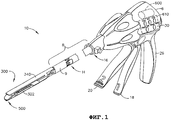
Фиг. 1 - вид в перспективе хирургического отрезного и фиксирующего аппарата, в котором можно применять различные варианты осуществления концевого эффектора и различные варианты осуществления кассеты для скобок в соответствии с настоящим изобретением;FIG. 1 is a perspective view of a surgical cutting and fixing apparatus in which various embodiments of an end effector and various embodiments of a cassette for brackets in accordance with the present invention can be applied;
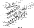
Фиг. 2 - общий вид с пространственным разделением деталей концевого эффектора в соответствии с вариантом осуществления настоящего изобретения;FIG. 2 is an exploded perspective view of an end effector according to an embodiment of the present invention;
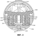
Фиг. 3 - вид в разрезе концевого эффектора в соответствии с вариантом осуществления настоящего изобретения, с установленной в нем кассетой для скобок в соответствии с вариантом осуществления настоящего изобретения, причем некоторые их компоненты не показаны для ясности;FIG. 3 is a cross-sectional view of an end effector in accordance with an embodiment of the present invention, with a cassette for brackets installed therein in accordance with an embodiment of the present invention, with some of their components not shown for clarity;
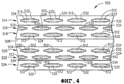
Фиг. 4 - местный вид сверху кассеты для скобок в соответствии с вариантом осуществления настоящего изобретения;FIG. 4 is a top plan view of a cassette for brackets in accordance with an embodiment of the present invention;
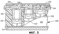
Фиг. 5 - местный вид в разрезе кассеты для скобок и концевого эффектора в соответствии с вариантом осуществления настоящего изобретения, с изображением прошивки скобками ткани, зажатой в концевой эффектор;FIG. 5 is a fragmentary cross-sectional view of the cassette for the brackets and the end effector in accordance with an embodiment of the present invention, showing the firmware with fabric brackets clamped in the end effector;
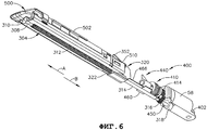
Фиг. 6 - вид снизу в перспективе концевого эффектора в соответствии с вариантом осуществления и кассеты для скобок в соответствии с вариантом осуществления настоящего изобретения с удалением из нее удлиненного желоба;FIG. 6 is a bottom perspective view of an end effector in accordance with an embodiment and a cassette for brackets in accordance with an embodiment of the present invention, removing an elongated trough from it;
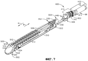
Фиг. 7 - местный вид в перспективе концевого эффектора в соответствии с вариантом осуществления и кассеты для скобок в соответствии с вариантом осуществления настоящего изобретения;FIG. 7 is a fragmentary perspective view of an end effector according to an embodiment and a cassette for brackets according to an embodiment of the present invention;
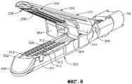
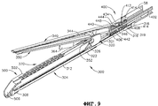
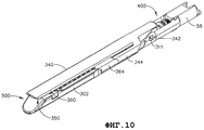
Фиг. 8 - вид в перспективе кассеты для скобок в соответствии с вариантом осуществления настоящего изобретения, установленной в концевом эффекторе в соответствии с вариантом осуществления настоящего изобретения, в разомкнутом положении;FIG. 8 is a perspective view of a cassette for brackets in accordance with an embodiment of the present invention installed in an end effector in accordance with an embodiment of the present invention in an open position;
Фиг. 9 - вид в разрезе концевого эффектора и кассеты для скобок, показанных на фиг. 8;FIG. 9 is a sectional view of the end effector and the cassette for the brackets shown in FIG. 8;
Фиг. 10 - вид в перспективе концевого эффектора и кассеты для скобок, показанных на фиг. 8 и 9;FIG. 10 is a perspective view of an end effector and a cassette for the brackets shown in FIG. 8 and 9;
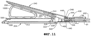
Фиг. 11 - вид в разрезе кассеты для скобок и концевого эффектора в соответствии с различными вариантами осуществления настоящего изобретения в разомкнутом положении до зажима в нем части ткани;FIG. 11 is a cross-sectional view of a cassette for brackets and an end effector in accordance with various embodiments of the present invention in the open position until a part of the tissue is clamped therein;
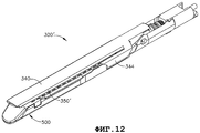
Фиг. 12 - вид в перспективе концевого эффектора и кассеты для скобок в соответствии с другим вариантом осуществления настоящего изобретения, в сомкнутом положении;FIG. 12 is a perspective view of an end effector and a cassette for brackets in accordance with another embodiment of the present invention, in a closed position;
Фиг. 13 - еще один вид в перспективе концевого эффектора и кассеты для скобок в варианте осуществления, показанном на фиг. 12, с изображением положения нижней планки упора до извлечения из концевого эффектора;FIG. 13 is yet another perspective view of the end effector and the cassette for the brackets in the embodiment shown in FIG. 12, showing the position of the lower stop plate before being removed from the end effector;
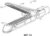
Фиг. 14 - вид в перспективе концевого эффектора и кассеты для скобок, показанных на фигурах 12 и 13, в разомкнутом положении;FIG. 14 is a perspective view of the end effector and cassette for the brackets shown in figures 12 and 13, in the open position;
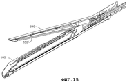
Фиг. 15 - вид в разрезе концевого эффектора и кассеты для скобок, показанных на фиг. 14;FIG. 15 is a sectional view of the end effector and the cassette for the brackets shown in FIG. fourteen;
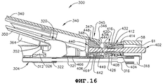
Фиг. 16 - местный увеличенный вид в разрезе концевого эффектора и кассеты для скобок в соответствии с различными вариантами настоящего изобретения, в разомкнутом положении;FIG. 16 is a fragmentary enlarged sectional view of an end effector and a cassette for brackets in accordance with various embodiments of the present invention, in the open position;
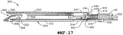
Фиг. 17 - вид в разрезе концевого эффектора и кассеты в сборе в соответствии с различными вариантами настоящего изобретения, в сомкнутом положении;FIG. 17 is a cross-sectional view of an end effector and a cartridge assembly in accordance with various embodiments of the present invention, in a closed position;
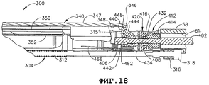
Фиг. 18 - местный увеличенный вид в разрезе концевого эффектора и кассеты для скобок, показанных на фиг. 17;FIG. 18 is a local enlarged sectional view of the end effector and the cassette for the brackets shown in FIG. 17;
Фиг. 19 - вид в перспективе дистального участка ведущего вала в соответствии с различными вариантами осуществления настоящего изобретения;FIG. 19 is a perspective view of a distal portion of a drive shaft in accordance with various embodiments of the present invention;
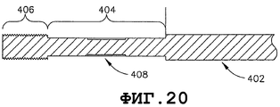
Фиг. 20 - вид в разрезе дистального участка ведущего вала, показанного на фиг. 19;FIG. 20 is a sectional view of a distal portion of a drive shaft shown in FIG. 19;
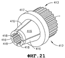
Фиг. 21 - вид в перспективе конусовидного элемента муфты сцепления в соответствии с различными вариантами осуществления настоящего изобретения;FIG. 21 is a perspective view of a cone-shaped clutch member in accordance with various embodiments of the present invention;
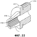
Фиг. 22 - вид в разрезе конусовидного элемента муфты сцепления, показанного на фигуре 21;FIG. 22 is a sectional view of the cone-shaped element of the clutch shown in FIG. 21;
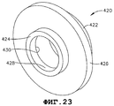
Фиг. 23 - вид в перспективе диска муфты сцепления в соответствии с различными вариантами осуществления настоящего изобретения;FIG. 23 is a perspective view of a clutch disc in accordance with various embodiments of the present invention;
Фиг. 24 - вид в разрезе диска муфты сцепления, показанного на фиг. 23;FIG. 24 is a sectional view of the clutch disc of FIG. 23;
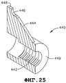
Фиг. 25 - вид в перспективе замыкающей гайки в соответствии с различными вариантами осуществления настоящего изобретения;FIG. 25 is a perspective view of a locking nut in accordance with various embodiments of the present invention;
Фиг. 26 - вид в разрезе замыкающей гайки, показанной на фиг. 25;FIG. 26 is a cross-sectional view of a locking nut shown in FIG. 25;
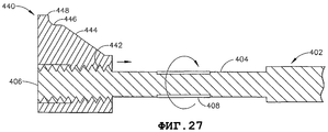
Фиг. 27 - вид в разрезе дистального участка ведущего вала и замыкающей гайки, с замыкающей гайкой в разомкнутом положении; иFIG. 27 is a sectional view of a distal portion of a drive shaft and a locking nut, with a locking nut in an open position; and
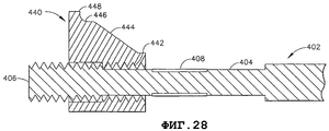
Фиг. 28 - другой вид в разрезе дистального участка ведущего вала и замыкающей гайки, с замыкающей гайкой в сомкнутом положении.FIG. 28 is another sectional view of a distal portion of the drive shaft and the locking nut, with the locking nut in the closed position.
ПОДРОБНОЕ ОПИСАНИЕDETAILED DESCRIPTION
На фиг. 1 изображен хирургический отрезной и фиксирующий аппарат 10, который способен на практике реализовать разнообразные специфические преимущества конструкций концевых эффекторов и/или конструкций кассет для скобок в соответствии с настоящим изобретением. Хирургический аппарат 10, изображенный на фиг. 1, содержит рукоятку 6, узел 8 стержня и шарнирно-поворотный концевой эффектор 300, соединенный с возможностью поворота с узлом 8 стержня в шарнире 14 сочленения. В различных вариантах осуществления управляющая рукоятка вмещает приводной электродвигатель 600 и систему управления, обозначенную, в общем, позицией 610 на данной фигуре, для управления размыканием и смыканием концевого эффектора 300 и отрезанием и сшиванием скобками ткани, зажатой в данном эффекторе. Вблизи рукоятки 6 может быть обеспечено устройство 16 управления шарнирным поворотом для осуществления поворота концевого эффектора 300 на шарнире 14 сочленения. Рукоятка 6 аппарата 10 может содержать замыкающий рычаг 18 и рычаг 20 прошивки для приведения в действие концевого эффектора 300. Концевой эффектор 300 показан отделенным от рукоятки 6 предпочтительно удлиненным стержнем 8. В одном варианте осуществления врач или хирург, оперирующий аппаратом 10, может шарнирно поворачивать концевой эффектор 300 относительно стержня 8 с помощью устройства 16 управления шарнирным поворотом, как более подробно описано в находящейся на рассмотрении заявке на патент США № 11/329,020, поданной 10 января 2006 г., «Surgical Instrument Having An Articulating End Effector», изобретателей Geoffrey C. Hueil et al., которая целиком включена в настоящее описание путем отсылки. Возможно также использование других конструктивных схем шарнирного поворота.In FIG. 1 depicts a surgical detachable and fixing
Как дополнительно подробнее поясняется ниже, различные варианты осуществления концевого эффектора содержат узел упора с поворотно-поступательным перемещением, который удерживается на некотором разделяющем расстоянии, которое обеспечивает эффективное сшивание скобками и отрезание ткани, зажатой в концевом эффекторе 300. В различных примерных вариантах осуществления рукоятка 6 может содержать ручку 26 пистолетного типа, к которой замыкающий рычаг 18 подтягивается поворотным движением врачом для осуществления зажима или смыкания верхней планки 340 упора и кассеты 500, находящейся в удлиненном желобе 302 концевого эффектора 300, чтобы, тем самым, зажать ткань, расположенную между верхней планкой 340 упора и кассетой 500 для скобок. Рычаг 20 прошивки может находиться дальше снаружи от замыкающего рычага 18. В различных вариантах осуществления, после того как замыкающий рычаг 18 зафиксируется в положении примыкания, как дополнительно поясняется ниже, рычаг 20 прошивки может сделать небольшой поворот к ручке 26 пистолетного типа настолько, что его сможет достать оперирующий хирург, работающий одной рукой. Затем оперирующий хирург может подтянуть поворотным движением рычаг 20 прошивки к ручке 26 пистолетного типа для осуществления сшивания скобками и отрезания ткани, зажатой в концевом эффекторе 300. Однако специалистам со средним уровнем компетентности в данной области техники совершенно очевидна возможность успешного применения других конструктивных схем рукоятки и системы привода в связи с различными вариантами осуществления, описанными в настоящей заявке, и эквивалентными им конструкциями, без выхода за пределы существа и объема настоящего изобретения.As further explained in more detail below, various embodiments of the end effector comprise a stop assembly with a rotary-translational movement that is held at a certain separation distance that provides effective stapling and cutting of tissue clamped in the
Далее следует понимать, что в настоящем описании термины «проксимальный» и «дистальный» применяют для обозначения положения относительно захвата практикующим врачом рукоятки 6 аппарата 10. Следовательно, концевой эффектор 300 является дистальным относительно более проксимальной рукоятки 6. Дополнительно следует понимать, что для удобства и ясности специальные термины, обозначающие пространственное положение, например, «вертикальный» и «горизонтальный», использованы в настоящем описании применительно к чертежам. Однако существует множество пространственно-угловых положений применения хирургических аппаратов, и упомянутые термины не предполагают ограничительного и абсолютного значения.It should further be understood that in the present description, the terms “proximal” and “distal” are used to indicate the position relative to the grasp by the practitioner of the
На фиг. 2-11 изображен специфический и новый концевой эффектор 300 в соответствии с различными вариантами осуществления настоящего изобретения. Из настоящего подробного описания должно быть понятно, что концевой эффектор 300, представленный на фигурах, может вмещать разные кассеты 500 для скобок. Например, концевой эффектор 300 может вмещать 45-мм и 60-мм одноразовые кассеты для скобок, которые имеют корпуса кассет, которые одинаковы по длине. Упомянутые корпуса кассет для скобок и принцип их действия известны в технике и поэтому не описаны здесь подробнее. Например, в патенте США № 6,978,921, «Surgical Stapling Instrument Incorporating an E-beam Firing Mechanism», который целиком включен в настоящее описание путем отсылки, даются дополнительные сведения и конструкции такого рода кассет для скобок.In FIG. 2-11, a specific and
В общем, различные кассеты 500 для скобок содержат корпус 502 кассеты, который разделен центральной удлиненной прорезью 508, которая продолжается от проксимального конца 504 корпуса 502 кассеты к его клиновидной внешней оконечности 506. Смотри фиг. 2. Корпус 502 кассеты может быть выполнен из полимерного материала и присоединен к металлическому кассетному лотку 510. В различных конструктивных схемах корпус 502 кассеты для 45-мм кассеты, например, будет иметь длину, которая равна длине «L» корпуса 502 кассеты для 60-мм кассеты. Множество вмещающих скобки углублений 512 выполнено в корпусе 502 кассеты и расположено в шесть поперечно разнесенных продольных строчек или «рядов» скобок 514, 516, 518, 520, 522, 524. Смотри фиг. 5. Кроме того, в различных вариантах осуществления длина «L» рядов скобок для 45-мм кассеты будет короче, чем длина «L» рядов в 60-мм кассете. Техническому специалисту совершенно очевидно, что кассеты 45-мм и 60-мм размеров использованы в настоящем описании только для примера. Кассеты других размеров с другими рядами скобок могут охватывать специфические и новые аспекты различных вариантов осуществления настоящего изобретения.In general,
Внутри углублений 512 находятся опорные поводки 532 скобок, которые служат опорой для скобок 534. В зависимости от местоположения (ряда) вмещающих скобки углублений 512, опорные поводки 532 скобок могут служить опорой для одной или двух скобок 530. Корпус 502 кассеты дополнительно содержит четыре продольных паза 503, 505, 507, 509, продолжающихся от проксимального конца 504 корпуса до его клиновидной внешней оконечности 506, для вмещения соответствующих кулачков 328 скользящего блока, сформированных на клиновидном скользящем блоке 326 в концевом эффекторе 300, конструкция и действие которого дополнительно подробнее поясняются ниже. Смотри фиг. 3. Когда кулачки 328 скользящего блока выдвигаются по соответствующим им пазам 503, 505, 507, 509 в корпусе 502 кассеты от проксимального конца 504 к дистальному концу 506, они входят в контакт с опорными поводками 532 скобок, связанными с теми пазами, и выталкивают опорные поводки 532 скобок и скобки 534, которые на них опираются, вверх из корпуса 502 кассеты. Смотри фигуру 6. Когда концы ножек 536 скобок 534 входят в контакт с углублениями 358, сформированными в нижней планке 350 упора, они складываются с закрыванием скобок 534.Inside the
Из настоящего подробного описания должно быть также очевидно, что различные специфические и новые аспекты различных вариантов осуществления настоящего изобретения позволяют изготавливать многие из компонентов концевого эффектора из металлического листа со снижением, тем самым, общей стоимости концевого эффектора. Другие компоненты концевого эффектора могут содержать механически обработанные детали.It should also be apparent from the present detailed description that various specific and novel aspects of various embodiments of the present invention make it possible to fabricate many of the components of the end effector from a metal sheet, thereby reducing the overall cost of the end effector. Other end effector components may include machined parts.
Различные концевые эффекторы по настоящему изобретению содержат удлиненный желоб 302, который выполнен с размером для установки и закрепления в нем с возможностью извлечения корпуса 502 одноразовой кассеты 500. Из описания понятно, что в различных вариантах осуществления удлиненный желоб 302 выполнен с возможностью выполнения функции опоры для любого из одноразмерных корпусов кассет для скобок, независимо от длины рядов скобок, установленных в них. Ходовой винт 304 ножа закреплен с возможностью вращения в удлиненном желобе 302. Ходовой винт 304 ножа имеет дистальный конец 306, который содержит дистальный упорный подшипник 308, закрепленный на нем, который установлен с возможностью вращения в дистальном гнезде 310 подшипника, выполненном в дистальном конце 303 удлиненного желоба 302. Смотри фиг. 2. Ходовой винт 304 ножа имеет центральный ходовой участок 312 со сформированной на нем цилиндрической резьбой. Ходовой винт 304 ножа дополнительно имеет гладкий удлинительный участок 314 и шестерню 316 ходового винта ножа, выполненную или иначе закрепленную на данном участке. Проксимальный упорный подшипник 318 выполнен или закреплен на проксимальном конце 317 ходового винта 304 ножа. Проксимальный упорный подшипник 318 посажен с возможностью вращения в проксимальное гнездо 319 подшипника, установленное в дистальном сегменте 58 несущей трубки. Смотри фиг. 9. Дистальный сегмент 58 несущей трубки содержит пару стоек 59, сформированных на его дистальном конце, которые выполнены с возможностью вмещения в вертикальные пазы 307, сформированные в проксимальном конце 305 удлиненного желоба 302. Стойки 59 могут фиксироваться в пазах 307 в удлиненном желобе 302 за счет трения, клеем или дистальным концом стержневой трубки 9. Смотри фиг. 1.The various end effectors of the present invention comprise an
Различные варианты осуществления настоящего изобретения дополнительно содержат узел 320 ножа, который содержит несущую часть 322 ножа/скользящего блока, которая установлена на резьбе на резьбовом участке 312 ходового винта 304 ножа. Узел 320 ножа служит опорой для вертикально продолжающего лезвия 324 и клиновидного скользящего блока 326, который служит опорой для четырех кулачков 328 скользящего блока. Из настоящего подробного описания должно быть понятно, что, когда ходовой винт 304 ножа вращается в направлении по часовой стрелке, узел 320 ножа и клиновидный скользящий блок 326 перемещаются к дистальному концу 303 (направление «A») удлиненного желоба 302, и, когда ходовой винт 304 ножа поворачивается в направлении против часовой стрелки, узел 320 ножа и клиновидный скользящий блок 326 перемещаются к проксимальному концу 305 желобчатого элемента 302 (направление «B»). Как можно видеть на фиг. 9, в различных вариантах осуществления узел 320 ножа содержит плоский несущий участок 322, который выполнен с возможностью сдвига по внутренней поверхности дна удлиненного желоба 302 и обеспечивает опору для узла 320 ножа и скользящего блока 326 по мере того, как те перемещаются вперед внутри удлиненного желоба 302. Кроме того, узел 320 ножа содержит пару выступающих из него поперечно продолжающихся отклоняющих лапок 330, назначение которого поясняется далее.Various embodiments of the present invention further comprise a
В различных вариантах осуществления настоящего изобретения верхняя планка 340 упора соединена с возможностью поворота с проксимальным концом 305 желобчатого элемента 302 парой пальцев 342 качающейся опоры, которые выполнены с размером для установки в шарнирные отверстия 311 с овальным поперечным сечением, выполненные сквозь боковые стенки 309 желобчатого элемента 302. В различных вариантах осуществления верхняя планка 340 упора выполнена из жесткого материала для сведения к минимуму любого отклонения или коробления верхнего элемента упора во время применения. Верхняя планка 340 упора предназначена для сопряжения с нижней планкой 350 упора, которая прикреплена к проксимальному концу 504 кассеты 500 для скобок, по меньшей мере, одной, но предпочтительно двумя пружинами 352. В различных вариантах осуществления один участок 353 каждой из пружин 352 прикреплен к корпусу 502 кассеты клеем, в пазы, механическим крепежом и т.п. Другой участок 354 каждой из пружин 352 прикреплен к нижней поверхности 356 нижней планки 350 упора клеем, в пазы, механическим крепежом и т.п. Смотри фиг. 2. Как можно видеть на фиг. 8, нижняя поверхность 356 нижней планки 350 упора содержит ряды сформированных в ней скобкоформирующих углублений 358. Из настоящего описания должно быть понятно, что в различных вариантах осуществления нижняя планка 350 упора может быть прикреплена к корпусу 502 кассеты так, что скобкоформирующие углубления 358 совмещены с соответствующими вмещающими скобки углублениями 512 в корпусе 502 кассеты. Следует понимать, что скобкоформирующие углубления 358 служат для закрывания скобок 534 по мере того, как концы ножек 536 скобок выдвигаются в контакт с данными углублениями. Смотри фиг. 6. Кроме того, в различных вариантах осуществления аналогичные углубления для скобок (не показанные) могут быть сформированы в нижней поверхности 341 верхней планки 340 упора. Из настоящего подробного описания должно быть очевидно, что такая конструкция верхней планки упора дает возможность эффективного применения концевого эффектора 300 с кассетами 500, которые не содержат нижних упоров, связанных с ними, а также с кассетами 500, которые содержат такие нижние упоры, прикрепленные или иным образом связанные с ними.In various embodiments of the present invention, the
В различных вариантах осуществления нижняя планка 350 упора может быть непосредственно прикреплена к корпусу 302 кассеты и упакована совместно с ним. Однако в других вариантах осуществления нижняя планка 350 упора может быть упакована отдельно и может устанавливаться пользователем на кассете 500 перед применением. Например, верхняя поверхность 503 корпуса 502 кассеты может быть снабжена парой пазов или других крепежных конструкций, которые выполнены с возможностью закрепления в них участков 353 пружин 352. В других вариантах осуществления, например, нижняя планка 350 упора может быть прикреплена к верхней планке упора на защелке и т.п. Таким образом, очевидно, что в различных вариантах осуществления настоящего изобретения нижняя планка 350 упора не обязательно должна крепиться к корпусу 502 кассеты для скобок. Нижняя планка 350 упора должна быть просто «связана с» конкретной соответствующей кассетой для скобок. В настоящем описании термин «связанный с» означает, что нижняя планка 350 упора выполнена с возможностью совмещения с конкретной кассетой для скобок, чтобы, когда скобки выталкиваются из кассеты в упор с нижней планкой 350 упора, нижняя планка 350 упора вынуждала скобки 534 формироваться заданным образом, и предназначен для охвата таких конструктивных схем, в которых нижняя планка 350 упора непосредственно присоединена к корпусу 502 кассеты для скобок, временно присоединяется к верхней планке 340 упора, и таких конструктивных схем, в которых нижняя планка 350 упора иным способом фиксируется согласованно с корпусом 502 кассеты для скобок между верхней планкой 340 упора и корпусом 502 кассеты для скобок во время размещения скобок 534 в ткани, зажатой в концевом эффекторе 300.In various embodiments, the
В различных вариантах осуществления, например, нижняя планка 350 упора снабжена парой реек 360 жесткости, которые продолжаются вдоль каждой боковой кромки 359 нижней планки 350 упора так, что, когда узел кассеты/нижней планки упора, обозначенный, в целом, позицией 370, установлен в удлиненный желоб 302, верхняя планка 340 упора вмещается между рейками 360 жесткости с образованием узла 372 упора. Из настоящего описания очевидно, что рейки 360 жесткости служат для усиления узла 372 упора и могут служить для крепления нижней планки 350 упора защелкиванием к верхней планке 340 упора. В различных вариантах осуществления нижняя планка 350 упора может быть штампованной или иным образом вальцованной или сформированной из металлического листа или тонкослойного листового материала, способного к изгибу, так что после применения ее выбрасывают с корпусом 502 кассеты для скобок. Следовательно, применительно к различным вариантам осуществления настоящего изобретения, нижняя планка 350 упора может в настоящем описании именоваться «одноразовой планкой упора» или «одноразовым упором».In various embodiments, for example, the
Кроме того, по центру нижней планки 350 упора может быть выполнена продольная прорезь 362 для установки сквозь нее верхнего конца узла 320 ножа. Между нижней поверхностью 341 верхней планки 340 упора и верхней поверхностью 357 нижней планки 350 упора может быть обеспечено достаточное пространство, чтобы поперечно продолжающиеся отклоняющие лапки 330, сформированные на верхнем конце узла 320 ножа, служили для скольжения по верхней поверхности 357 нижней планки 350 упора и поджима нижней планки 350 упора к корпусу 502 кассеты, когда узел 320 ножа и клиновидный скользящий блок 326 продвигаются вдоль кассеты 520 для отрезания ткани и постановки скобок 534. Кроме того, в нижней поверхности 341 верхней планки 340 упора может быть образована продольная прорезь 343 для вмещения в нее верхнего конца узла 320 ножа.In addition, a longitudinal slot 362 may be made in the center of the
Другим специфическим и новым аспектом настоящего изобретения является возможность эффективного применения различных вариантов осуществления концевого эффектора в связи с кассетами для скобок, которые имеют разные длины «L» рядов скобок. Например, в различных вариантах осуществления настоящего изобретения применяются фиксаторы 364 ткани на нижней планке 350 упора. Кроме того, для поддержки данных «первых» фиксаторов 364 ткани на нижней планке 350 упора на верхней планке 340 упора сформирована пара верхних фиксаторов 344 ткани для дублирования и подпора (иначе «взаимодействия с») первых фиксаторов 364 ткани, когда кассетный узел 500 установлен в желоб, как показано на фиг. 8-11. Специалисту в данной области техники очевидно, что назначение местоположения первых фиксаторов 364 ткани на нижней планке 350 упора может быть, в частности, подогнано соответственно позициям самых внутренних вмещающих скобки углублений 512 на одноразовой кассете 500 для скобок, к которой прикреплена данная планка. Как дополнительно подробнее поясняется ниже, данный специфический и новый аспект настоящего изобретения дает возможность использования множества разных кассет в концевом эффекторе, которые имеют разные длины «L» рядов скобок (например, 45-мм, 60 мм и т.п.).Another specific and new aspect of the present invention is the ability to effectively use various embodiments of the end effector in connection with cassettes for brackets that have different lengths “L” of rows of brackets. For example, in various embodiments of the present invention,
В других вариантах осуществления, в которых в нижней поверхности 341 верхней планки 340 упора не образовано никаких скобкоформирующих углублений, нижнюю планку 350 упора можно использовать, как описано выше, с такими кассетами 500 для скобок, которые содержат более длинные ряды скобок, которые могут рассчитывать только на верхние фиксаторы 344 ткани для ориентации ткани таким образом, чтобы не допускать захода ткани на всю длину в конструкцию упора/кассеты и обусловленного этим отрезания без сшивания скобками. Таким образом, как можно видеть на фигурах 15-19, для извлечения израсходованной кассеты 500 из желоба 302, на нижнюю планку 350 упора нажимают, и кассету и нижнюю планку 350 упора можно извлекать из дистального конца 303 удлиненного желоба 302. Смотри фиг. 13.In other embodiments, in which no brace-forming recesses are formed in the
Ниже описание узла привода для управления различными вариантами осуществления концевого эффектора 300 приведено со ссылками на фиг. 2 и 18-29. Как можно видеть на фиг. 2 и 17-19, дистальный участок 402 ведущего вала продолжается через отверстие 61 под ведущий вал в дистальной несущей трубке 58. Дистальный участок 402 ведущего вала может продолжаться прямо в конструкцию приводного электродвигателя в управляющей рукоятке 6 или может быть шарнирно-поворотным для создания возможности поворота концевого эффектора 300 относительно стержня или узла замыкающей трубки, которая соединяет концевой эффектор 300 с управляющей трубкой 6. Хотя данные аспекты не составляют главный предмет изобретения, ниже кратко поясняются различные альтернативные конструктивные схемы.Below, a description of a drive assembly for controlling various embodiments of the
Как можно видеть на фиг. 20, 21, 28 и 29, дистальный участок 402 ведущего вала содержит участок 404 установки муфты сцепления и выполненную на нем замыкающую резьбу 406. Муфтовый узел 410 может сдвигом устанавливаться на участок 404 установки муфты сцепления дистального участка 402 ведущего вала. Как можно видеть на фиг. 2, 22 и 23, муфтовый узел 410 содержит цанговый конусный элемент 412 муфты сцепления, который содержит ведущую шестерню 414, выполненную как одно целое с ним на его проксимальном конце 413. Ведущая шестерня 414 находится в зацеплении с передаточной шестерней 450, которая в свою очередь находится в зацеплении с шестерней 316 ходового винта ножа. Смотри фиг. 2, 6 и 7. Таким образом, когда муфтовый узел 410 входит в приводное зацепление с дистальным участком 402 ведущего вала, ведущая шестерня 414 вращает передаточную шестерню 450, которая в свою очередь вращает шестерню 316 ходового винта ножа.As can be seen in FIG. 20, 21, 28, and 29, the
Группа из четырех конусных секций 416 сформирована на дистальном конце 415 конусного элемента 412 муфты сцепления. Внутри конусных секций 416 образована группа охватываемых шлицов 418. Смотри фиг. 22 и 23. Охватываемые шлицы 418 выполнены с возможностью избирательного зацепления с секцией 408 охватывающих шлицов, образованных на дистальном участке 402 ведущего вала, как дополнительно подробнее поясняется ниже. Смотри фиг. 20 и 21. Муфтовый узел 410 дополнительно содержит диск 420 муфты сцепления, который насаживается на конусные секции 416 конусного элемента 412 муфты сцепления. Как можно видеть на фиг. 24 и 25, диск 420 муфты сцепления содержит проксимальный участок 422 ступицы и дистальный участок 424 ступицы, которые разделены фланцевым участком 426. Участок 428 цилиндрического дистального отверстия продолжается сквозь дистальный участок 424 ступицы, и коническое проксимальное отверстие 430 продолжается сквозь фланцевый участок 426 и проксимальный участок 422 ступицы. Смотри фиг. 25. Участки 428, 430 отверстий дают возможность диску 420 муфты сцепления сдвигаться к ведущему валу 402 и надвигаться на конусный элемент 412 муфты сцепления. Пружина расцепления муфты обеспечена между фланцевым участком 417, сформированным на конусном элементе 412 муфты сцепления, и фланцевым участком 426 диска 420 муфты сцепления, и упорный подшипник 434 также установлен на участке 404 установки муфты сцепления, примыкающий к диску 420 муфты сцепления. Смотри фиг. 2, 17 и 19.A group of four
В различных вариантах осуществления замыкающая гайка 440 устанавливается на дистальном участке 402 ведущего вала. Как можно видеть на фиг. 27-28, замыкающая гайка 440 имеет участок 442 резьбового отверстия, продолжающийся частично сквозь данную гайку, чтобы она могла навинчиваться на замыкающую резьбу 406 на дистальном участке 402 ведущего вала. Как дополнительно можно видеть на данных фигурах, замыкающая гайка 440 имеет вертикальный замыкающий наклонный выступ 444, выступающий из данной гайки. Верх замыкающего наклонного выступа 444 заканчивается закругленным по радиусу участком 446, который продолжается в вертикальную замыкающую лапку 448, которая выполнена с возможностью зацепления с выступающим вниз замыкающим зацепом 346, сформированным на проксимальном конце 345 верхней планки 340 упора.In various embodiments, a locking
В частности, и как показано на фиг. 17 и 18, проксимальный конец 345 верхней планки 340 упора содержит консольный участок 347 смыкания упора, проксимально выступающий из упомянутой планки, который заканчивается продолжающимся вниз замыкающим зацепом 346. Как также можно видеть на данных фигурах, нижняя поверхность консоли 347 смыкания упора содержит выполненную в ней канавку 348 разгрузки лапки для вмещения замыкающей лапки 448, когда замыкающая гайка 440 выдвинута в ее крайнее дистальное положение (показанное на фиг. 17 и 28). Кроме того, в различных вариантах осуществления к низу желобчатого элемента 302 прикреплена пружина 460 фиксации замыкания механическими крепежными конструкциями или клеем. Пружина 460 фиксации замыкания имеет верхний участок 462, который заканчивается выступающей вверх стопорной кромкой 464. В дополнение продольно продолжающаяся стопорная консоль жестко прикреплена к верхнему участку 462 пружины 460 фиксации замыкания.In particular, and as shown in FIG. 17 and 18, the
Ниже, со ссылками на фиг. 9, 11, 17-19 и 28-29, приведено описание функционирования различных вариантов осуществления настоящего изобретения. На фиг. 9, 11 и 17 изображен концевой эффектор 300 в разомкнутом положении. Как можно видеть на данных фигурах, в разомкнутом положении замыкающий зацеп 346 консоли верхней планки 340 упора передвигается по наклонно выступающему участку 444 замыкающей гайки 440. В данном положении верхняя планка 340 упора повернута в разомкнутое положение. Кроме того, в данном положении конец стопорной консоли 466, которая прикреплена к пружине 460 фиксации замыкания, находится в контакте с наклонной поверхностью 321, сформированной на проксимальном конце узла 320 ножа. Когда узел 320 ножа перемещается в проксимальном направлении, конец стопорной консоли 466 входит в контакт с наклонной поверхностью 321 на проксимальном конце узла 320 ножа и служит для передачи через стопорную консоль 466 на верхний участок 462 пружины 460 фиксации замыкания поджимного усилия вниз к дну удлиненного желоба 302. Когда узел 320 ножа перемещается в дистальном направлении от упорной консоли 466, верхний участок 462 пружины 460 фиксации замыкания получает возможность пружинно отгибаться вверх с предоставлением стопорной кромке 464 возможности входа в зацепление с замыкающей гайкой 440, как дополнительно поясняется ниже. Как также можно видеть на фигурах, в разомкнутом положении замыкающая лапка 448 находится в канавке 348 разгрузки лапки на нижней поверхности верхней планки 340 упора.Below, with reference to FIG. 9, 11, 17-19 and 28-29, a description is given of the functioning of various embodiments of the present invention. In FIG. 9, 11, and 17 show an
Из настоящего описания должно быть очевидно, что, когда концевой эффектор 300 находится в разомкнутом положении, показанном на фигурах 9, 11 и 17, пользователь может установить кассетный узел 500 в удлиненный элемент 302. Когда дистальный участок 402 ведущего вала вращается в первом направлении, его замыкающая резьба 406 сдвигает по резьбе замыкающую гайку 440 в проксимальном направлении (направлении «A» на фиг. 28), пока замыкающая резьба 406 не выйдет из зацепления с резьбовым отверстием 442 в замыкающей гайке 440. Смотри фиг. 29. По мере того как замыкающая гайка 440 сдвигается в проксимальном направлении, замыкающий зацеп 346 на консоли 347 смыкания упора наезжает на наклонный выступ 444 замыкающей гайки 440, пока не попадет в закругленный по радиусу участок 446 и не войдет в контакт с замыкающей лапкой 448. Такое перемещение замыкающей гайки 440 служит для «подтягивания» узла 372 упора (верхней планки 340 упора и нижней планки 350 упора) в сомкнутое положение, показанное на фиг. 18 и 19.From the present description it should be obvious that when the
По мере того как замыкающая гайка 440 приводится в движение в проксимальном направлении, проксимальный конец 449 замыкающей гайки 440 входит в контакт с упорным подшипником 434, который прижимает диск 420 муфты сцепления в проксимальном направлении против усилия пружины 432 расцепления муфты. Дополнительное продвижение замыкающей гайки 440 в проксимальном направлении сдвигает диск 420 муфты сцепления на конусные секции 416 конусного элемента 412 муфты сцепления, что вынуждает охватываемые шлицы 418 данного элемента входить в зацепление с охватывающими шлицами 408 на дистальном участке 402 ведущего вала. Такое зацепление охватываемых шлицов 418 в конусном элементе 412 муфты сцепления с охватывающими шлицами на дистальном участке 402 ведущего вала приводит к совместному вращению конусного элемента 412 муфты сцепления и ведущей шестерни 414 с дистальным участком 402 ведущего вала. Ведущая шестерня 414, в свою очередь, вращает шестерню 316 ходового винта ножа, которая вынуждает ходовой винт ножа вращаться и приводить в движение узел ножа в дистальном направлении (направлении «B»).As the locking
По мере того как узел 320 ножа сдвигается в дистальном направлении, поперечно продолжающиеся направляющие лапки 330 входят в зацепление с верхней поверхностью нижней планки 350 упора и выполняют функцию подтягивания нижней планки 350 упора вниз для дополнительного зажима ткани между нижней планкой 350 упора и корпусом 502 кассеты. Лезвие 324 ножа на узле 320 ножа отрезает ткань, и кулачки 328 на клиновидном скользящем блоке 326 выполняют функцию выталкивания вверх опорных поводков 532 скобок, которые выталкивают скобки 534 к нижней планке 350 упора. По мере того как ножки 536 скобок 534 выталкиваются в соответствующие скобкоформирующие углубления 358 в нижней планке 350 упора, они загибаются. Смотри фиг. 6. В таких вариантах осуществления, в которых на нижней планке 350 упора выполнен, по меньшей мере, один фиксатор 364 ткани, фиксаторы 364 ткани взаимодействуют с верхними фиксаторами 344 ткани на верхней планке 340 упора для предотвращения захода ткани слишком далеко в конструкцию кассеты/упора за самые внутренние скобки и, тем самым, для предотвращения отрезания ткани, которая не будет сшита скобками. Аналогично в таких вариантах осуществления концевого эффектора, в которых также имеются скобкоформирующие углубления, сформированные в нижней поверхности верхней планки 340 упора, и не применяется нижняя планка упора, верхние фиксаторы 344 ткани являются достаточно жесткими для выполнения вышеупомянутой функции, обеспечивающей требование, чтобы не происходило отрезания ткани, которая не будет сшита скобками. Что касается таких вариантов осуществления концевого эффектора 300′ (фиг. 12-16), в которых применяется нижняя планка 350′ упора, не оборудованная фиксаторами ткани, то такие варианты осуществления выполнены в предположении, что верхние фиксаторы 344 ткани на верхней планке 340 упора должны ориентировать ткань относительно скобок в кассете 500 для предотвращения, тем самым, отрезания ткани, которая не будет сшита скобками.As the
Когда узел 320 ножа перемещается в дистальном направлении, стопорная консоль 466 больше не находится в контакте с наклонной поверхностью 321 узла 320 ножа, что дает возможность стопорной консоли 466 и верхнему участку 462 пружины 460 фиксации замыкания пружинно отогнуться вверх, что дополнительно позволяет стопорной кромке 464 на пружине 460 фиксации замыкания войти в фиксирующееся зацепление с дистальным концом замыкающей гайки 440 для предотвращения ее перемещения в дистальном направлении. Смотри фиг. 17 и 18. Благодаря контакту стопорной кромки 464 с замыкающей гайкой 440, которая находится в контакте с упорным подшипником 434, упомянутая кромка выполняет функцию удерживания муфтового узла 410, находящегося в зацеплении с дистальным участком 402 ведущего вала, пока узел 320 ножа снова не вернется в контакт со стопорной консолью 466. После того как узел 320 ножа сдвинут в его конечное дистальное положение, как показано на фиг. 17, он включает обычный датчик или контакт 313, установленный в удлиненном желобе 302, и подает сигнал в управляющий электродвигатель на останов приведения в движение ведущего вала 402. Смотри фиг. 2. Специалистам со средним уровнем компетентности в данной области техники будет понятно, что можно применить множество различных управляющих конструкций для управления ведущим валом 402. Например, когда узел 320 ножа достигает своего крайнего дистального положения и включает датчик 313, система 610 управления, расположенная в рукоятке 6 может автоматически реверсировать приводной электродвигатель 600 в данной рукоятке и вызвать реверсирование участка 402 ведущего вала и винта ножа (например, вызвать перемещение в проксимальном направлении «A»). В различных других вариантах осуществления система 610 управления может просто остановить приводной электродвигатель 600 и затем потребовать от хирурга включения кнопки 30, чтобы вызвать реверсирование электродвигателя 600. В некоторых других конструктивных схемах система 610 управления может вводить заданную временную задержку между моментом, когда датчик 313 реверса включается, и моментом, когда электродвигатель 600 реверсируется.When the
По мере того как узел 320 ножа перемещается в проксимальном направлении на ходовом винте 304 ножа, замыкающая резьба 406 на ведущем валу 402 начинает вывинчиваться на участке 442 резьбового отверстия замыкающей гайки 440. В ходе данного процесса наклонная поверхность 321 узла 320 ножа снова входит в контакт с концом стопорной консоли 466, которая выполняет функцию поджима верхнего участка 462 пружины 460 фиксации замыкания к низу удлиненного желоба 302 с созданием для стопорной кромки 464 возможности отцепления от дистального конца замыкающей гайки 440, что позволяет пружине 432 расцепления муфты отжать муфтовый узел 410 и замыкающую гайку 440 в дистальном направлении. По мере того как замыкающая гайка 440 перемещается в дистальном направлении, замыкающий зацеп 346 на верхней планке упора надвигается на наклонный выступ 444 на замыкающей гайке, пока замыкающая гайка 440 не достигнет разомкнутого положения, в котором замыкающая лапка 448 контактирует с канавкой 348 разгрузки лапки в верхней планке 340 упора, и замыкающая гайка 440 перемещает узел 372 упора в разомкнутое положение. Второй обычный датчик или контакт 315 установлен внутри проксимального концевого участка 305 удлиненного желоба 302 для определения, когда замыкающая гайка 440 находится в разомкнутом положении и передает сигнал в электродвигатель, чтобы вызвать его остановку. Смотри фиг. 2.As the
Как указано выше, возможно применение множества различных конструктивных схем управления электродвигателем для вращения участка 402 ведущего вала. Например, в различных вариантах осуществления, когда замыкающий рычаг 18 приведен в действие, то есть притянут пользователем аппарата 10, электродвигатель 600 может начать вышеописанный процесс смыкания. Третий датчик 315′ можно использовать в удлиненном желобчатом элементе 302 для определения, когда замыкающая гайка 404 переведена в сомкнутое положение (показанное на фигуре). Когда третий датчик 315′ определяет, что замыкающая гайка 440 находится в данном положении, датчик 315′ может предписать электродвигателю 600 останов вращения. После этого, если хирург удовлетворен зажимом ткани в концевом эффекторе 300, хирург может привести в действие рычаг 20 прошивки или другое исполнительное приспособление для включения электродвигателя 600 на вращение ведущего вала 402, который приводит в движение узел 304 ножа вышеописанным образом.As indicated above, it is possible to use many different structural schemes for controlling the motor to rotate the
Из вышеприведенного описания с очевидностью следует, что различные варианты осуществления настоящего изобретения отражают многочисленные улучшения по сравнению с прежними хирургическими отрезными и фиксирующими концевыми эффекторами и кассетами. В частности, различные варианты осуществления настоящего изобретения позволяют применять кассеты разных конфигураций в одном и том же концевом эффекторе. Другие признаки, по меньшей, некоторых вариантов осуществления настоящего изобретения включают в себя обеспечение кассет для скобок, которые более экономичны в изготовлении и которые требуют развития меньших усилий прошивки/отрезания аппаратом для отрезания и сшивания скобками ткани. Кроме того, другие признаки различных вариантов осуществления настоящего изобретения обеспечивают концевые эффекторы, которые можно использовать для многократной установки скобок в толстой ткани с применением усилий прошивки/отрезания, которые обычно ниже, чем усилия прошивки/отрезания, необходимые в, по меньшей мере, некоторых известных конструкциях концевых эффекторов.It clearly follows from the above description that various embodiments of the present invention reflect numerous improvements over previous surgical detachable and fixing end effectors and cassettes. In particular, various embodiments of the present invention allow the use of cassettes of different configurations in the same end effector. Other features of at least some embodiments of the present invention include the provision of cassettes for brackets that are more economical to manufacture and which require the development of less stitching / cutting efforts by the apparatus for cutting and stapling fabric brackets. In addition, other features of various embodiments of the present invention provide end effectors that can be used to repeatedly place brackets in thick tissue using the firmware / cut forces that are typically lower than the firmware / cut forces required in at least some known end effector designs.
Любые патенты, публикации или другие данные, целиком или частично, которые упомянуты как включенные в настоящее описание путем отсылки, включены в настоящее описание только в таких пределах, в которых включенные данные не противоречат существующим определениям, формулировкам или другим данным, представленным в настоящем описании. По существу, сведения, приведенные в явном виде в настоящем описании, заменяют собой любые противоречащие данные, включенные в настоящее описание путем ссылки.Any patents, publications or other data, in whole or in part, which are mentioned as being incorporated into this description by reference, are included in this description only to such extent that the data included do not contradict the existing definitions, wordings or other data presented in the present description. Essentially, the information provided explicitly in the present description, replaces any conflicting data included in the present description by reference.
Изобретение, предлагаемое к охране, нельзя толковать как ограниченное конкретными описанными вариантами осуществления. Поэтому варианты осуществления следует считать иллюстративными, а не ограничивающими. Другими специалистами могут быть созданы варианты и внесены изменения без выхода за пределы существа настоящего изобретения. Соответственно, прямо предполагается, что настоящим документом должны охватываться все такие эквиваленты, варианты и изменения, которые находятся в пределах существа и объема настоящего изобретения, определенных формулой изобретения.The invention proposed for protection cannot be interpreted as limited to the specific described options for implementation. Therefore, embodiments should be considered illustrative and not restrictive. Other specialists can create options and make changes without going beyond the merits of the present invention. Accordingly, it is expressly intended that this document should cover all such equivalents, variations, and changes that fall within the spirit and scope of the present invention as defined by the claims.
Claims (15)
корпус кассеты, служащий опорой для установки в нем с возможностью функционирования множества скобок;
одноразовый упор, установленный относительно упомянутого корпуса кассеты так, что упомянутый одноразовый упор может перемещаться между сомкнутым положением, в котором нижняя поверхность упомянутого одноразового упора примыкает к верхней поверхности упомянутого корпуса кассеты, и разомкнутым положением, в котором нижняя поверхность упомянутого одноразового упора находится на расстоянии от упомянутой верхней поверхности упомянутого корпуса кассеты для создания возможности ввода ткани между ними;
при этом одноразовый упор содержит верхнюю планку упора и нижнюю планку упора, снабженную рейками жесткости, продолжающимися вдоль каждой боковой кромки упомянутой нижней планки упора, для вмещения верхней планки упора между рейками жесткости; и
по меньшей мере, один фиксатор ткани на упомянутом одноразовом упоре для контакта с тканью, вводимой между нижней поверхностью одноразового упора и верхней поверхностью упомянутого корпуса кассеты, чтобы ориентировать ткань относительно скобок, установленных в упомянутом корпусе кассеты.1. Disposable cassette for brackets for surgical detachable and fixing apparatus, while said cassette for brackets contains:
cassette case, which serves as a support for installation in it with the possibility of the functioning of many brackets;
a disposable stop mounted relative to said cartridge case so that said disposable stop can move between an open position in which the lower surface of said disposable stop is adjacent to an upper surface of said cartridge case and an open position in which a lower surface of said disposable stop is at a distance from said upper surface of said cassette case to enable tissue input between them;
wherein the one-time stop comprises an upper stop bar and a lower stop bar provided with stiffeners extending along each lateral edge of said lower stop bar to accommodate an upper stop bar between the stiffeners; and
at least one tissue retainer on said disposable abutment for contacting tissue inserted between a lower surface of the disposable abutment and an upper surface of said cartridge case to orient the fabric with respect to brackets installed in said cartridge case.
желоб, имеющий проксимальный конец, присоединенный к участку хирургического отрезного и фиксирующего аппарата, при этом упомянутый желоб дополнительно имеет дистальный конец и выполнен с возможностью выполнения функции опоры для установки в нем одноразовой кассеты для скобок;
жесткую верхнюю планку упора, имеющую дистальный конец и проксимальный конец, при этом упомянутый проксимальный конец соединен с возможностью поворота с упомянутым проксимальным концом упомянутого желоба и может избирательно поворачиваться между разомкнутым положением, в котором упомянутый дистальный конец упомянутой верхней планки упора удален от упомянутого дистального конца упомянутого желоба для обеспечения возможности установки одноразовой кассеты для скобок в упомянутый желоб, и сомкнутым положением, в котором упомянутая верхняя планка упора примыкает к кассете для скобок, установленной в желобе, в ответ на размыкающее и смыкающее усилия, соответственно, прилагаемые к нему системой привода, установленной в хирургическом отрезном и фиксирующем аппарате, причем упомянутая жесткая верхняя планка упора выполнена с возможностью сопряжения с одноразовой планкой упора, связанной с одноразовой кассетой для скобок, установленной в желобе, при этом упомянутая жесткая верхняя планка упора выполнена с размером для установки с возможностью фиксации между ребрами жесткости на одноразовой планке упора;
узел ножа, установленный с возможностью функционирования в упомянутом желобе и соединенный с системой привода хирургического отрезного и фиксирующего аппарата для продвижения упомянутого узла ножа от упомянутого проксимального конца упомянутого желоба к упомянутому дистальному концу и возвращения упомянутого узла ножа к упомянутому проксимальному концу упомянутого желоба; и
клиновидный скользящий блок, связанный с упомянутым узлом ножа для перемещения вместе с ним, при этом упомянутый клиновидный скользящий блок ориентирован для приведения в движение поводков скобок в одноразовой кассете для скобок, установленной в желобе, когда упомянутый узел ножа продвигается от упомянутого проксимального конца упомянутого желоба к упомянутому дистальному концу упомянутого желоба.10. An end effector for a surgical cutting and fixing apparatus, wherein said end effector comprises:
a groove having a proximal end attached to a section of a surgical cutting and fixing apparatus, wherein said groove further has a distal end and is configured to support the installation of a disposable brace cartridge in it;
a rigid upper stop bar having a distal end and a proximal end, wherein said proximal end is rotatably connected with said proximal end of said trough and can selectively rotate between an open position in which said distal end of said upper stop bar is removed from said distal end of said gutters to enable the installation of a disposable cassette for brackets in said gutter, and in a closed position in which said the upper stop plate adjoins the cassette for the brackets installed in the gutter, in response to the opening and closing forces, respectively, of the drive system installed in it, installed in the surgical cutting and fixing apparatus, said rigid upper stop plate being made to be coupled to the disposable strip an abutment associated with a disposable cassette for brackets mounted in a trough, wherein said rigid upper abutment plate is dimensioned for installation with the possibility of fixing between the ribs sharpness on a one-time emphasis plate;
a knife assembly that is operable in said trough and connected to a surgical cutting and fixing apparatus drive system for moving said knife assembly from said proximal end of said groove to said distal end and returning said knife assembly to said proximal end of said groove; and
the wedge-shaped sliding block associated with the said node of the knife to move with him, while the said wedge-shaped sliding block is oriented to drive the leads of the brackets in a disposable cassette for brackets mounted in the gutter, when the said node of the knife moves from the said proximal end of the said gutter to said distal end of said trough.
удлиненный желоб, присоединяемый к участку хирургического отрезного и фиксирующего аппарата, причем упомянутый удлиненный желоб выполнен с возможностью выполнения функции опоры для установки в нем любого из корпусов кассет для скобок и других корпусов кассет для скобок;
верхнюю планку упора, соединенную с возможностью поворота с упомянутым удлиненным желобом и способную к перемещению между разомкнутым и сомкнутым положениями в ответ на размыкающее и смыкающее усилия, соответственно, прилагаемые к ней системой привода, установленной в хирургическом отрезном и фиксирующем аппарате, причем упомянутая верхняя планка упора содержит, по меньшей мере, один верхний фиксатор ткани, связанный с ней, выполненный с возможностью взаимодействия, с по меньшей мере, одним из фиксаторов ткани, связанных с одним из корпусов кассет, когда упомянутый корпус кассеты установлен в упомянутом удлиненном желобе, чтобы ориентировать ткань относительно рядов скобок в нем, причем упомянутый, по меньшей мере, один верхний фиксатор ткани дополнительно выполнен с возможностью ориентирования ткани, зажатой между верхним упором и одним из других корпусов кассет для скобок, когда упомянутый другой корпус кассеты вмещен в упомянутый удлиненный желоб так, что упомянутый, по меньшей мере, один верхний фиксатор ткани ориентирует ткань относительно, по меньшей мере, одного другого ряда других скобок в упомянутом другом корпусе кассеты для скобок; и
узел ножа и поводков скобок, установленный с возможностью функционирования в упомянутом удлиненном желобе и выполненный с возможностью восприятия направленного вперед приводного и реверсного движений от системы привода хирургического отрезного и фиксирующего аппарата, так что, когда упомянутый узел ножа и скобок приводится в движение вперед, ткань, зажатая в концевом эффекторе, тем самым, отрезается и сшивается скобками, установленными в кассете, размещенной в удлиненном желобе. 15. The end effector for a surgical cutting and fixing apparatus, structurally configured to be used in conjunction with at least one of a plurality of cassette cases for brackets, each of which has a typical length, and each cassette case for brackets serves as a support for installation in it with the possibility of functioning of many brackets that are located in a straight line in at least one first row of brackets, and contains at least one tissue retainer associated with it, and the end effector will complement It is completely structurally designed to be used with at least one other bracket cassette case from another set of other bracket cassette cases, each of which has a length equal to the typical length of the bracket cassette cases, and each serves as a support for installation in it with the possibility of functioning of many other brackets that are located in a straight line in at least one other row of other brackets, which is longer than the rows of brackets in the casings of the brackets, and said end effector contains:
an elongated trough attached to a portion of the surgical cutting and fixing apparatus, said elongated trough being configured to support the installation of any of the cassette cases for brackets and other cassette cases for the brackets therein;
the upper stop plate connected with the possibility of rotation with the said elongated trough and capable of moving between open and closed positions in response to the opening and closing forces, respectively, applied to it by a drive system installed in a surgical cutting and fixing apparatus, said upper stop plate contains at least one upper tissue retainer associated with it, configured to interact with at least one of the tissue retainers associated with one of the body cartridge cassettes, when said cartridge case is mounted in said elongated groove to orient the fabric relative to the rows of brackets in it, said at least one upper fabric retainer being further configured to orient the fabric sandwiched between the upper stop and one of the other cartridge cases for brackets, when said other cassette case is housed in said elongated groove so that said at least one upper fabric retainer orientates the fabric with respect to at least one about another set of other brackets in said other cassette bracket case; and
a node of the knife and leashes of brackets, installed with the possibility of functioning in the said elongated trough and made with the possibility of perceiving forward-directed drive and reverse movements from the drive system of the surgical cutting and fixing apparatus, so that when the said node of the knife and brackets is driven forward, the fabric, sandwiched in the end effector, thereby, is cut off and stapled with brackets installed in the cassette located in the elongated groove.
Applications Claiming Priority (2)
| Application Number | Priority Date | Filing Date | Title |
|---|---|---|---|
| US11/343,546 US20070175950A1 (en) | 2006-01-31 | 2006-01-31 | Disposable staple cartridge having an anvil with tissue locator for use with a surgical cutting and fastening instrument and modular end effector system therefor |
| US11/343,546 | 2006-01-31 |
Publications (2)
| Publication Number | Publication Date |
|---|---|
| RU2007103553A RU2007103553A (en) | 2008-08-10 |
| RU2449749C2 true RU2449749C2 (en) | 2012-05-10 |
Family
ID=37906946
Family Applications (1)
| Application Number | Title | Priority Date | Filing Date |
|---|---|---|---|
| RU2007103553/14A RU2449749C2 (en) | 2006-01-31 | 2007-01-30 | Disposable cassette for staples containing stop with tissue fixer for application with surgical cutting and fixing apparatus and module system of end effector for said apparatus |
Country Status (14)
| Country | Link |
|---|---|
| US (1) | US20070175950A1 (en) |
| EP (1) | EP1813209B1 (en) |
| JP (1) | JP5148123B2 (en) |
| KR (1) | KR101369235B1 (en) |
| CN (1) | CN101069649B (en) |
| AT (1) | ATE476146T1 (en) |
| AU (1) | AU2007200311B2 (en) |
| BR (1) | BRPI0703043B8 (en) |
| CA (1) | CA2576340C (en) |
| DE (1) | DE602007008154D1 (en) |
| HK (1) | HK1106414A1 (en) |
| MX (1) | MX2007001315A (en) |
| RU (1) | RU2449749C2 (en) |
| SG (1) | SG134306A1 (en) |
Families Citing this family (961)
| Publication number | Priority date | Publication date | Assignee | Title |
|---|---|---|---|---|
| US5865361A (en) | 1997-09-23 | 1999-02-02 | United States Surgical Corporation | Surgical stapling apparatus |
| US7464847B2 (en) | 2005-06-03 | 2008-12-16 | Tyco Healthcare Group Lp | Surgical stapler with timer and feedback display |
| US10285694B2 (en) | 2001-10-20 | 2019-05-14 | Covidien Lp | Surgical stapler with timer and feedback display |
| US20070084897A1 (en) | 2003-05-20 | 2007-04-19 | Shelton Frederick E Iv | Articulating surgical stapling instrument incorporating a two-piece e-beam firing mechanism |
| US9060770B2 (en) | 2003-05-20 | 2015-06-23 | Ethicon Endo-Surgery, Inc. | Robotically-driven surgical instrument with E-beam driver |
| US10041822B2 (en) | 2007-10-05 | 2018-08-07 | Covidien Lp | Methods to shorten calibration times for powered devices |
| US10022123B2 (en) | 2012-07-09 | 2018-07-17 | Covidien Lp | Surgical adapter assemblies for use between surgical handle assembly and surgical end effectors |
| US11311291B2 (en) | 2003-10-17 | 2022-04-26 | Covidien Lp | Surgical adapter assemblies for use between surgical handle assembly and surgical end effectors |
| US8215531B2 (en) | 2004-07-28 | 2012-07-10 | Ethicon Endo-Surgery, Inc. | Surgical stapling instrument having a medical substance dispenser |
| US11890012B2 (en) | 2004-07-28 | 2024-02-06 | Cilag Gmbh International | Staple cartridge comprising cartridge body and attached support |
| US8905977B2 (en) | 2004-07-28 | 2014-12-09 | Ethicon Endo-Surgery, Inc. | Surgical stapling instrument having an electroactive polymer actuated medical substance dispenser |
| US7947034B2 (en) | 2004-07-30 | 2011-05-24 | Tyco Healthcare Group Lp | Flexible shaft extender and method of using same |
| US11291443B2 (en) | 2005-06-03 | 2022-04-05 | Covidien Lp | Surgical stapler with timer and feedback display |
| CA2609970C (en) | 2005-06-03 | 2014-08-12 | Tyco Healthcare Group Lp | Battery powered surgical instrument |
| US11246590B2 (en) | 2005-08-31 | 2022-02-15 | Cilag Gmbh International | Staple cartridge including staple drivers having different unfired heights |
| US10159482B2 (en) | 2005-08-31 | 2018-12-25 | Ethicon Llc | Fastener cartridge assembly comprising a fixed anvil and different staple heights |
| US7669746B2 (en) | 2005-08-31 | 2010-03-02 | Ethicon Endo-Surgery, Inc. | Staple cartridges for forming staples having differing formed staple heights |
| US11484312B2 (en) | 2005-08-31 | 2022-11-01 | Cilag Gmbh International | Staple cartridge comprising a staple driver arrangement |
| US9237891B2 (en) | 2005-08-31 | 2016-01-19 | Ethicon Endo-Surgery, Inc. | Robotically-controlled surgical stapling devices that produce formed staples having different lengths |
| US20070194079A1 (en) | 2005-08-31 | 2007-08-23 | Hueil Joseph C | Surgical stapling device with staple drivers of different height |
| US7934630B2 (en) | 2005-08-31 | 2011-05-03 | Ethicon Endo-Surgery, Inc. | Staple cartridges for forming staples having differing formed staple heights |
| US8800838B2 (en) | 2005-08-31 | 2014-08-12 | Ethicon Endo-Surgery, Inc. | Robotically-controlled cable-based surgical end effectors |
| US7673783B2 (en) | 2005-11-04 | 2010-03-09 | Ethicon Endo-Surgery, Inc. | Surgical stapling instruments structured for delivery of medical agents |
| US7673780B2 (en) * | 2005-11-09 | 2010-03-09 | Ethicon Endo-Surgery, Inc. | Articulation joint with improved moment arm extension for articulating an end effector of a surgical instrument |
| US20070106317A1 (en) | 2005-11-09 | 2007-05-10 | Shelton Frederick E Iv | Hydraulically and electrically actuated articulation joints for surgical instruments |
| US7799039B2 (en) | 2005-11-09 | 2010-09-21 | Ethicon Endo-Surgery, Inc. | Surgical instrument having a hydraulically actuated end effector |
| US7670334B2 (en) | 2006-01-10 | 2010-03-02 | Ethicon Endo-Surgery, Inc. | Surgical instrument having an articulating end effector |
| US7568603B2 (en) | 2006-01-31 | 2009-08-04 | Ethicon Endo-Surgery, Inc. | Motor-driven surgical cutting and fastening instrument with articulatable end effector |
| US8763879B2 (en) | 2006-01-31 | 2014-07-01 | Ethicon Endo-Surgery, Inc. | Accessing data stored in a memory of surgical instrument |
| US11278279B2 (en) | 2006-01-31 | 2022-03-22 | Cilag Gmbh International | Surgical instrument assembly |
| US11224427B2 (en) | 2006-01-31 | 2022-01-18 | Cilag Gmbh International | Surgical stapling system including a console and retraction assembly |
| US7845537B2 (en) | 2006-01-31 | 2010-12-07 | Ethicon Endo-Surgery, Inc. | Surgical instrument having recording capabilities |
| US8186555B2 (en) | 2006-01-31 | 2012-05-29 | Ethicon Endo-Surgery, Inc. | Motor-driven surgical cutting and fastening instrument with mechanical closure system |
| US7644848B2 (en) | 2006-01-31 | 2010-01-12 | Ethicon Endo-Surgery, Inc. | Electronic lockouts and surgical instrument including same |
| US20110024477A1 (en) | 2009-02-06 | 2011-02-03 | Hall Steven G | Driven Surgical Stapler Improvements |
| US11793518B2 (en) | 2006-01-31 | 2023-10-24 | Cilag Gmbh International | Powered surgical instruments with firing system lockout arrangements |
| US20110290856A1 (en) | 2006-01-31 | 2011-12-01 | Ethicon Endo-Surgery, Inc. | Robotically-controlled surgical instrument with force-feedback capabilities |
| US7770775B2 (en) | 2006-01-31 | 2010-08-10 | Ethicon Endo-Surgery, Inc. | Motor-driven surgical cutting and fastening instrument with adaptive user feedback |
| US9861359B2 (en) | 2006-01-31 | 2018-01-09 | Ethicon Llc | Powered surgical instruments with firing system lockout arrangements |
| US7766210B2 (en) | 2006-01-31 | 2010-08-03 | Ethicon Endo-Surgery, Inc. | Motor-driven surgical cutting and fastening instrument with user feedback system |
| US8161977B2 (en) * | 2006-01-31 | 2012-04-24 | Ethicon Endo-Surgery, Inc. | Accessing data stored in a memory of a surgical instrument |
| US8820603B2 (en) | 2006-01-31 | 2014-09-02 | Ethicon Endo-Surgery, Inc. | Accessing data stored in a memory of a surgical instrument |
| US8708213B2 (en) | 2006-01-31 | 2014-04-29 | Ethicon Endo-Surgery, Inc. | Surgical instrument having a feedback system |
| US20110006101A1 (en) | 2009-02-06 | 2011-01-13 | EthiconEndo-Surgery, Inc. | Motor driven surgical fastener device with cutting member lockout arrangements |
| US20120292367A1 (en) | 2006-01-31 | 2012-11-22 | Ethicon Endo-Surgery, Inc. | Robotically-controlled end effector |
| US7753904B2 (en) | 2006-01-31 | 2010-07-13 | Ethicon Endo-Surgery, Inc. | Endoscopic surgical instrument with a handle that can articulate with respect to the shaft |
| US8721630B2 (en) | 2006-03-23 | 2014-05-13 | Ethicon Endo-Surgery, Inc. | Methods and devices for controlling articulation |
| US8992422B2 (en) | 2006-03-23 | 2015-03-31 | Ethicon Endo-Surgery, Inc. | Robotically-controlled endoscopic accessory channel |
| US20070225562A1 (en) | 2006-03-23 | 2007-09-27 | Ethicon Endo-Surgery, Inc. | Articulating endoscopic accessory channel |
| US7552854B2 (en) | 2006-05-19 | 2009-06-30 | Applied Medical Resources Corporation | Surgical stapler with firing lock mechanism |
| US8322455B2 (en) | 2006-06-27 | 2012-12-04 | Ethicon Endo-Surgery, Inc. | Manually driven surgical cutting and fastening instrument |
| US7740159B2 (en) | 2006-08-02 | 2010-06-22 | Ethicon Endo-Surgery, Inc. | Pneumatically powered surgical cutting and fastening instrument with a variable control of the actuating rate of firing with mechanical power assist |
| US10130359B2 (en) | 2006-09-29 | 2018-11-20 | Ethicon Llc | Method for forming a staple |
| US10568652B2 (en) | 2006-09-29 | 2020-02-25 | Ethicon Llc | Surgical staples having attached drivers of different heights and stapling instruments for deploying the same |
| US7506791B2 (en) | 2006-09-29 | 2009-03-24 | Ethicon Endo-Surgery, Inc. | Surgical stapling instrument with mechanical mechanism for limiting maximum tissue compression |
| US7845535B2 (en) | 2006-10-06 | 2010-12-07 | Tyco Healthcare Group Lp | Surgical instrument having a plastic surface |
| US8733614B2 (en) | 2006-10-06 | 2014-05-27 | Covidien Lp | End effector identification by mechanical features |
| US11291441B2 (en) | 2007-01-10 | 2022-04-05 | Cilag Gmbh International | Surgical instrument with wireless communication between control unit and remote sensor |
| US7721931B2 (en) | 2007-01-10 | 2010-05-25 | Ethicon Endo-Surgery, Inc. | Prevention of cartridge reuse in a surgical instrument |
| US7954682B2 (en) | 2007-01-10 | 2011-06-07 | Ethicon Endo-Surgery, Inc. | Surgical instrument with elements to communicate between control unit and end effector |
| US8684253B2 (en) | 2007-01-10 | 2014-04-01 | Ethicon Endo-Surgery, Inc. | Surgical instrument with wireless communication between a control unit of a robotic system and remote sensor |
| US7721936B2 (en) * | 2007-01-10 | 2010-05-25 | Ethicon Endo-Surgery, Inc. | Interlock and surgical instrument including same |
| US7900805B2 (en) | 2007-01-10 | 2011-03-08 | Ethicon Endo-Surgery, Inc. | Surgical instrument with enhanced battery performance |
| US7738971B2 (en) * | 2007-01-10 | 2010-06-15 | Ethicon Endo-Surgery, Inc. | Post-sterilization programming of surgical instruments |
| US8459520B2 (en) | 2007-01-10 | 2013-06-11 | Ethicon Endo-Surgery, Inc. | Surgical instrument with wireless communication between control unit and remote sensor |
| US8652120B2 (en) | 2007-01-10 | 2014-02-18 | Ethicon Endo-Surgery, Inc. | Surgical instrument with wireless communication between control unit and sensor transponders |
| US11039836B2 (en) | 2007-01-11 | 2021-06-22 | Cilag Gmbh International | Staple cartridge for use with a surgical stapling instrument |
| US8540128B2 (en) | 2007-01-11 | 2013-09-24 | Ethicon Endo-Surgery, Inc. | Surgical stapling device with a curved end effector |
| US7431188B1 (en) | 2007-03-15 | 2008-10-07 | Tyco Healthcare Group Lp | Surgical stapling apparatus with powered articulation |
| US8727197B2 (en) | 2007-03-15 | 2014-05-20 | Ethicon Endo-Surgery, Inc. | Staple cartridge cavity configuration with cooperative surgical staple |
| US8056787B2 (en) | 2007-03-28 | 2011-11-15 | Ethicon Endo-Surgery, Inc. | Surgical stapling and cutting instrument with travel-indicating retraction member |
| US8893946B2 (en) | 2007-03-28 | 2014-11-25 | Ethicon Endo-Surgery, Inc. | Laparoscopic tissue thickness and clamp load measuring devices |
| US7950560B2 (en) | 2007-04-13 | 2011-05-31 | Tyco Healthcare Group Lp | Powered surgical instrument |
| US20080255413A1 (en) | 2007-04-13 | 2008-10-16 | Michael Zemlok | Powered surgical instrument |
| US11259801B2 (en) | 2007-04-13 | 2022-03-01 | Covidien Lp | Powered surgical instrument |
| US8800837B2 (en) * | 2007-04-13 | 2014-08-12 | Covidien Lp | Powered surgical instrument |
| US7823760B2 (en) | 2007-05-01 | 2010-11-02 | Tyco Healthcare Group Lp | Powered surgical stapling device platform |
| US7931660B2 (en) | 2007-05-10 | 2011-04-26 | Tyco Healthcare Group Lp | Powered tacker instrument |
| US7810693B2 (en) * | 2007-05-30 | 2010-10-12 | Ethicon Endo-Surgery, Inc. | Surgical stapling and cutting instrument with articulatable end effector |
| US7798386B2 (en) | 2007-05-30 | 2010-09-21 | Ethicon Endo-Surgery, Inc. | Surgical instrument articulation joint cover |
| US8157145B2 (en) | 2007-05-31 | 2012-04-17 | Ethicon Endo-Surgery, Inc. | Pneumatically powered surgical cutting and fastening instrument with electrical feedback |
| US8931682B2 (en) | 2007-06-04 | 2015-01-13 | Ethicon Endo-Surgery, Inc. | Robotically-controlled shaft based rotary drive systems for surgical instruments |
| US7832408B2 (en) * | 2007-06-04 | 2010-11-16 | Ethicon Endo-Surgery, Inc. | Surgical instrument having a directional switching mechanism |
| US8534528B2 (en) | 2007-06-04 | 2013-09-17 | Ethicon Endo-Surgery, Inc. | Surgical instrument having a multiple rate directional switching mechanism |
| US7819299B2 (en) | 2007-06-04 | 2010-10-26 | Ethicon Endo-Surgery, Inc. | Surgical instrument having a common trigger for actuating an end effector closing system and a staple firing system |
| US11857181B2 (en) | 2007-06-04 | 2024-01-02 | Cilag Gmbh International | Robotically-controlled shaft based rotary drive systems for surgical instruments |
| US7905380B2 (en) | 2007-06-04 | 2011-03-15 | Ethicon Endo-Surgery, Inc. | Surgical instrument having a multiple rate directional switching mechanism |
| US7510107B2 (en) * | 2007-06-18 | 2009-03-31 | Ethicon Endo-Surgery, Inc. | Cable driven surgical stapling and cutting instrument with apparatus for preventing inadvertent cable disengagement |
| US7753245B2 (en) | 2007-06-22 | 2010-07-13 | Ethicon Endo-Surgery, Inc. | Surgical stapling instruments |
| US7441685B1 (en) | 2007-06-22 | 2008-10-28 | Ethicon Endo-Surgery, Inc. | Surgical stapling instrument with a return mechanism |
| US7597229B2 (en) * | 2007-06-22 | 2009-10-06 | Ethicon Endo-Surgery, Inc. | End effector closure system for a surgical stapling instrument |
| US7658311B2 (en) | 2007-06-22 | 2010-02-09 | Ethicon Endo-Surgery, Inc. | Surgical stapling instrument with a geared return mechanism |
| US8308040B2 (en) | 2007-06-22 | 2012-11-13 | Ethicon Endo-Surgery, Inc. | Surgical stapling instrument with an articulatable end effector |
| US11849941B2 (en) | 2007-06-29 | 2023-12-26 | Cilag Gmbh International | Staple cartridge having staple cavities extending at a transverse angle relative to a longitudinal cartridge axis |
| US8061576B2 (en) | 2007-08-31 | 2011-11-22 | Tyco Healthcare Group Lp | Surgical instrument |
| US7988026B2 (en) | 2007-09-06 | 2011-08-02 | Cardica, Inc. | Endocutter with staple feed |
| US9168039B1 (en) | 2007-09-06 | 2015-10-27 | Cardica, Inc. | Surgical stapler with staples of different sizes |
| US8070036B1 (en) | 2007-09-06 | 2011-12-06 | Cardica, Inc | True multi-fire surgical stapler configured to fire staples of different sizes |
| US8403956B1 (en) | 2007-09-06 | 2013-03-26 | Cardica, Inc. | Multiple-use surgical stapler |
| WO2009039510A1 (en) | 2007-09-21 | 2009-03-26 | Power Medical Interventions, Inc. | Surgical device |
| US10779818B2 (en) | 2007-10-05 | 2020-09-22 | Covidien Lp | Powered surgical stapling device |
| US8960520B2 (en) | 2007-10-05 | 2015-02-24 | Covidien Lp | Method and apparatus for determining parameters of linear motion in a surgical instrument |
| US8967443B2 (en) | 2007-10-05 | 2015-03-03 | Covidien Lp | Method and apparatus for determining parameters of linear motion in a surgical instrument |
| US10498269B2 (en) | 2007-10-05 | 2019-12-03 | Covidien Lp | Powered surgical stapling device |
| US8517241B2 (en) | 2010-04-16 | 2013-08-27 | Covidien Lp | Hand-held surgical devices |
| US7922063B2 (en) | 2007-10-31 | 2011-04-12 | Tyco Healthcare Group, Lp | Powered surgical instrument |
| US8348129B2 (en) | 2009-10-09 | 2013-01-08 | Ethicon Endo-Surgery, Inc. | Surgical stapler having a closure mechanism |
| US8453908B2 (en) | 2008-02-13 | 2013-06-04 | Ethicon Endo-Surgery, Inc. | Surgical stapling instrument with improved firing trigger arrangement |
| US8540133B2 (en) | 2008-09-19 | 2013-09-24 | Ethicon Endo-Surgery, Inc. | Staple cartridge |
| US7766209B2 (en) | 2008-02-13 | 2010-08-03 | Ethicon Endo-Surgery, Inc. | Surgical stapling instrument with improved firing trigger arrangement |
| US8561870B2 (en) | 2008-02-13 | 2013-10-22 | Ethicon Endo-Surgery, Inc. | Surgical stapling instrument |
| US9179912B2 (en) | 2008-02-14 | 2015-11-10 | Ethicon Endo-Surgery, Inc. | Robotically-controlled motorized surgical cutting and fastening instrument |
| US7861906B2 (en) | 2008-02-14 | 2011-01-04 | Ethicon Endo-Surgery, Inc. | Surgical stapling apparatus with articulatable components |
| US7857185B2 (en) * | 2008-02-14 | 2010-12-28 | Ethicon Endo-Surgery, Inc. | Disposable loading unit for surgical stapling apparatus |
| US8573465B2 (en) | 2008-02-14 | 2013-11-05 | Ethicon Endo-Surgery, Inc. | Robotically-controlled surgical end effector system with rotary actuated closure systems |
| US8752749B2 (en) | 2008-02-14 | 2014-06-17 | Ethicon Endo-Surgery, Inc. | Robotically-controlled disposable motor-driven loading unit |
| US7866527B2 (en) | 2008-02-14 | 2011-01-11 | Ethicon Endo-Surgery, Inc. | Surgical stapling apparatus with interlockable firing system |
| BRPI0901282A2 (en) | 2008-02-14 | 2009-11-17 | Ethicon Endo Surgery Inc | surgical cutting and fixation instrument with rf electrodes |
| US8636736B2 (en) | 2008-02-14 | 2014-01-28 | Ethicon Endo-Surgery, Inc. | Motorized surgical cutting and fastening instrument |
| US8758391B2 (en) | 2008-02-14 | 2014-06-24 | Ethicon Endo-Surgery, Inc. | Interchangeable tools for surgical instruments |
| US7810692B2 (en) | 2008-02-14 | 2010-10-12 | Ethicon Endo-Surgery, Inc. | Disposable loading unit with firing indicator |
| US7819298B2 (en) | 2008-02-14 | 2010-10-26 | Ethicon Endo-Surgery, Inc. | Surgical stapling apparatus with control features operable with one hand |
| US8459525B2 (en) | 2008-02-14 | 2013-06-11 | Ethicon Endo-Sugery, Inc. | Motorized surgical cutting and fastening instrument having a magnetic drive train torque limiting device |
| US7819297B2 (en) | 2008-02-14 | 2010-10-26 | Ethicon Endo-Surgery, Inc. | Surgical stapling apparatus with reprocessible handle assembly |
| US7793812B2 (en) | 2008-02-14 | 2010-09-14 | Ethicon Endo-Surgery, Inc. | Disposable motor-driven loading unit for use with a surgical cutting and stapling apparatus |
| US8622274B2 (en) | 2008-02-14 | 2014-01-07 | Ethicon Endo-Surgery, Inc. | Motorized cutting and fastening instrument having control circuit for optimizing battery usage |
| US7819296B2 (en) | 2008-02-14 | 2010-10-26 | Ethicon Endo-Surgery, Inc. | Surgical stapling apparatus with retractable firing systems |
| US8584919B2 (en) | 2008-02-14 | 2013-11-19 | Ethicon Endo-Sugery, Inc. | Surgical stapling apparatus with load-sensitive firing mechanism |
| US7913891B2 (en) | 2008-02-14 | 2011-03-29 | Ethicon Endo-Surgery, Inc. | Disposable loading unit with user feedback features and surgical instrument for use therewith |
| US8657174B2 (en) | 2008-02-14 | 2014-02-25 | Ethicon Endo-Surgery, Inc. | Motorized surgical cutting and fastening instrument having handle based power source |
| US20090206137A1 (en) * | 2008-02-15 | 2009-08-20 | Ethicon Endo-Surgery, Inc. | Disposable loading units for a surgical cutting and stapling instrument |
| US20090206141A1 (en) | 2008-02-15 | 2009-08-20 | Ethicon Endo-Surgery, Inc. | Buttress material having an activatable adhesive |
| US8608044B2 (en) | 2008-02-15 | 2013-12-17 | Ethicon Endo-Surgery, Inc. | Feedback and lockout mechanism for surgical instrument |
| US9770245B2 (en) | 2008-02-15 | 2017-09-26 | Ethicon Llc | Layer arrangements for surgical staple cartridges |
| US11272927B2 (en) | 2008-02-15 | 2022-03-15 | Cilag Gmbh International | Layer arrangements for surgical staple cartridges |
| US7959051B2 (en) * | 2008-02-15 | 2011-06-14 | Ethicon Endo-Surgery, Inc. | Closure systems for a surgical cutting and stapling instrument |
| US20090206131A1 (en) | 2008-02-15 | 2009-08-20 | Ethicon Endo-Surgery, Inc. | End effector coupling arrangements for a surgical cutting and stapling instrument |
| US7980443B2 (en) * | 2008-02-15 | 2011-07-19 | Ethicon Endo-Surgery, Inc. | End effectors for a surgical cutting and stapling instrument |
| US7922061B2 (en) * | 2008-05-21 | 2011-04-12 | Ethicon Endo-Surgery, Inc. | Surgical instrument with automatically reconfigurable articulating end effector |
| US7942303B2 (en) | 2008-06-06 | 2011-05-17 | Tyco Healthcare Group Lp | Knife lockout mechanisms for surgical instrument |
| US8701959B2 (en) | 2008-06-06 | 2014-04-22 | Covidien Lp | Mechanically pivoting cartridge channel for surgical instrument |
| US7789283B2 (en) | 2008-06-06 | 2010-09-07 | Tyco Healthcare Group Lp | Knife/firing rod connection for surgical instrument |
| US8083120B2 (en) * | 2008-09-18 | 2011-12-27 | Ethicon Endo-Surgery, Inc. | End effector for use with a surgical cutting and stapling instrument |
| US7837080B2 (en) * | 2008-09-18 | 2010-11-23 | Ethicon Endo-Surgery, Inc. | Surgical stapling instrument with device for indicating when the instrument has cut through tissue |
| US20100069942A1 (en) * | 2008-09-18 | 2010-03-18 | Ethicon Endo-Surgery, Inc. | Surgical instrument with apparatus for measuring elapsed time between actions |
| PL3476312T3 (en) | 2008-09-19 | 2024-03-11 | Ethicon Llc | Surgical stapler with apparatus for adjusting staple height |
| US7857186B2 (en) * | 2008-09-19 | 2010-12-28 | Ethicon Endo-Surgery, Inc. | Surgical stapler having an intermediate closing position |
| US8215532B2 (en) | 2008-09-23 | 2012-07-10 | Tyco Healthcare Group Lp | Tissue stop for surgical instrument |
| US9050083B2 (en) | 2008-09-23 | 2015-06-09 | Ethicon Endo-Surgery, Inc. | Motorized surgical instrument |
| US8360298B2 (en) | 2008-09-23 | 2013-01-29 | Covidien Lp | Surgical instrument and loading unit for use therewith |
| US11648005B2 (en) | 2008-09-23 | 2023-05-16 | Cilag Gmbh International | Robotically-controlled motorized surgical instrument with an end effector |
| US9005230B2 (en) | 2008-09-23 | 2015-04-14 | Ethicon Endo-Surgery, Inc. | Motorized surgical instrument |
| US7896214B2 (en) | 2008-09-23 | 2011-03-01 | Tyco Healthcare Group Lp | Tissue stop for surgical instrument |
| US8628544B2 (en) | 2008-09-23 | 2014-01-14 | Covidien Lp | Knife bar for surgical instrument |
| US7988028B2 (en) | 2008-09-23 | 2011-08-02 | Tyco Healthcare Group Lp | Surgical instrument having an asymmetric dynamic clamping member |
| US9386983B2 (en) | 2008-09-23 | 2016-07-12 | Ethicon Endo-Surgery, Llc | Robotically-controlled motorized surgical instrument |
| US8210411B2 (en) | 2008-09-23 | 2012-07-03 | Ethicon Endo-Surgery, Inc. | Motor-driven surgical cutting instrument |
| US8608045B2 (en) | 2008-10-10 | 2013-12-17 | Ethicon Endo-Sugery, Inc. | Powered surgical cutting and stapling apparatus with manually retractable firing system |
| US8020743B2 (en) | 2008-10-15 | 2011-09-20 | Ethicon Endo-Surgery, Inc. | Powered articulatable surgical cutting and fastening instrument with flexible drive member |
| US7918377B2 (en) * | 2008-10-16 | 2011-04-05 | Ethicon Endo-Surgery, Inc. | Surgical stapling instrument with apparatus for providing anvil position feedback |
| US8517239B2 (en) | 2009-02-05 | 2013-08-27 | Ethicon Endo-Surgery, Inc. | Surgical stapling instrument comprising a magnetic element driver |
| US8397971B2 (en) | 2009-02-05 | 2013-03-19 | Ethicon Endo-Surgery, Inc. | Sterilizable surgical instrument |
| US8485413B2 (en) | 2009-02-05 | 2013-07-16 | Ethicon Endo-Surgery, Inc. | Surgical stapling instrument comprising an articulation joint |
| US8414577B2 (en) | 2009-02-05 | 2013-04-09 | Ethicon Endo-Surgery, Inc. | Surgical instruments and components for use in sterile environments |
| CN102341048A (en) | 2009-02-06 | 2012-02-01 | 伊西康内外科公司 | Driven surgical stapler improvements |
| US8444036B2 (en) * | 2009-02-06 | 2013-05-21 | Ethicon Endo-Surgery, Inc. | Motor driven surgical fastener device with mechanisms for adjusting a tissue gap within the end effector |
| US8356740B1 (en) | 2009-03-09 | 2013-01-22 | Cardica, Inc. | Controlling compression applied to tissue by surgical tool |
| US8397973B1 (en) | 2009-03-09 | 2013-03-19 | Cardica, Inc. | Wide handle for true multi-fire surgical stapler |
| US8066167B2 (en) | 2009-03-23 | 2011-11-29 | Ethicon Endo-Surgery, Inc. | Circular surgical stapling instrument with anvil locking system |
| US8292154B2 (en) | 2009-04-16 | 2012-10-23 | Tyco Healthcare Group Lp | Surgical apparatus for applying tissue fasteners |
| US8317072B1 (en) | 2009-05-03 | 2012-11-27 | Cardica, Inc. | Feeder belt for true multi-fire surgical stapler |
| US8631992B1 (en) | 2009-05-03 | 2014-01-21 | Cardica, Inc. | Feeder belt with padded staples for true multi-fire surgical stapler |
| US8365975B1 (en) | 2009-05-05 | 2013-02-05 | Cardica, Inc. | Cam-controlled knife for surgical instrument |
| US8127976B2 (en) | 2009-05-08 | 2012-03-06 | Tyco Healthcare Group Lp | Stapler cartridge and channel interlock |
| US9004339B1 (en) | 2009-05-26 | 2015-04-14 | Cardica, Inc. | Cartridgizable feeder belt for surgical stapler |
| US8070034B1 (en) | 2009-05-29 | 2011-12-06 | Cardica, Inc. | Surgical stapler with angled staple bays |
| US8240538B1 (en) | 2009-05-29 | 2012-08-14 | Cardica, Inc. | True multi-fire surgical stapler with two-sided staple deployment |
| US8225980B1 (en) | 2009-06-02 | 2012-07-24 | Cardica, Inc. | True multi-fire surgical stapler with buttress strip |
| US8056789B1 (en) | 2009-06-03 | 2011-11-15 | Cardica, Inc. | Staple and feeder belt configurations for surgical stapler |
| US8132706B2 (en) | 2009-06-05 | 2012-03-13 | Tyco Healthcare Group Lp | Surgical stapling apparatus having articulation mechanism |
| US8821514B2 (en) | 2009-06-08 | 2014-09-02 | Covidien Lp | Powered tack applier |
| US8087562B1 (en) | 2009-06-22 | 2012-01-03 | Cardica, Inc. | Anvil for surgical instrument |
| US8701960B1 (en) * | 2009-06-22 | 2014-04-22 | Cardica, Inc. | Surgical stapler with reduced clamp gap for insertion |
| US8342378B2 (en) | 2009-08-17 | 2013-01-01 | Covidien Lp | One handed stapler |
| US8365971B1 (en) | 2009-09-23 | 2013-02-05 | Cardica, Inc. | True multi-fire linear cutter |
| US8523042B2 (en) * | 2009-10-21 | 2013-09-03 | The General Hospital Corporation | Apparatus and method for preserving a tissue margin |
| US8225979B2 (en) | 2009-10-30 | 2012-07-24 | Tyco Healthcare Group Lp | Locking shipping wedge |
| US8418907B2 (en) | 2009-11-05 | 2013-04-16 | Covidien Lp | Surgical stapler having cartridge with adjustable cam mechanism |
| US8899466B2 (en) | 2009-11-19 | 2014-12-02 | Ethicon Endo-Surgery, Inc. | Devices and methods for introducing a surgical circular stapling instrument into a patient |
| US8136712B2 (en) | 2009-12-10 | 2012-03-20 | Ethicon Endo-Surgery, Inc. | Surgical stapler with discrete staple height adjustment and tactile feedback |
| US8851354B2 (en) | 2009-12-24 | 2014-10-07 | Ethicon Endo-Surgery, Inc. | Surgical cutting instrument that analyzes tissue thickness |
| US8220688B2 (en) | 2009-12-24 | 2012-07-17 | Ethicon Endo-Surgery, Inc. | Motor-driven surgical cutting instrument with electric actuator directional control assembly |
| US8267300B2 (en) | 2009-12-30 | 2012-09-18 | Ethicon Endo-Surgery, Inc. | Dampening device for endoscopic surgical stapler |
| US8261958B1 (en) | 2010-01-06 | 2012-09-11 | Cardica, Inc. | Stapler cartridge with staples frangibly affixed thereto |
| US8608046B2 (en) | 2010-01-07 | 2013-12-17 | Ethicon Endo-Surgery, Inc. | Test device for a surgical tool |
| KR101111213B1 (en) * | 2010-01-25 | 2012-02-14 | (주)트리플씨메디칼 | Gear-cam type anastomosis device |
| US8348127B2 (en) | 2010-04-07 | 2013-01-08 | Covidien Lp | Surgical fastener applying apparatus |
| US8662369B1 (en) | 2010-05-27 | 2014-03-04 | Cardica, Inc. | Barbed surgical staple |
| US8439246B1 (en) | 2010-07-20 | 2013-05-14 | Cardica, Inc. | Surgical stapler with cartridge-adjustable clamp gap |
| US8672207B2 (en) | 2010-07-30 | 2014-03-18 | Ethicon Endo-Surgery, Inc. | Transwall visualization arrangements and methods for surgical circular staplers |
| US8789740B2 (en) | 2010-07-30 | 2014-07-29 | Ethicon Endo-Surgery, Inc. | Linear cutting and stapling device with selectively disengageable cutting member |
| US8783543B2 (en) | 2010-07-30 | 2014-07-22 | Ethicon Endo-Surgery, Inc. | Tissue acquisition arrangements and methods for surgical stapling devices |
| US8360296B2 (en) * | 2010-09-09 | 2013-01-29 | Ethicon Endo-Surgery, Inc. | Surgical stapling head assembly with firing lockout for a surgical stapler |
| US9289212B2 (en) | 2010-09-17 | 2016-03-22 | Ethicon Endo-Surgery, Inc. | Surgical instruments and batteries for surgical instruments |
| US8632525B2 (en) | 2010-09-17 | 2014-01-21 | Ethicon Endo-Surgery, Inc. | Power control arrangements for surgical instruments and batteries |
| US9877720B2 (en) | 2010-09-24 | 2018-01-30 | Ethicon Llc | Control features for articulating surgical device |
| US8733613B2 (en) | 2010-09-29 | 2014-05-27 | Ethicon Endo-Surgery, Inc. | Staple cartridge |
| US11298125B2 (en) | 2010-09-30 | 2022-04-12 | Cilag Gmbh International | Tissue stapler having a thickness compensator |
| US9211120B2 (en) | 2011-04-29 | 2015-12-15 | Ethicon Endo-Surgery, Inc. | Tissue thickness compensator comprising a plurality of medicaments |
| US9629814B2 (en) | 2010-09-30 | 2017-04-25 | Ethicon Endo-Surgery, Llc | Tissue thickness compensator configured to redistribute compressive forces |
| US9220501B2 (en) | 2010-09-30 | 2015-12-29 | Ethicon Endo-Surgery, Inc. | Tissue thickness compensators |
| US9386988B2 (en) | 2010-09-30 | 2016-07-12 | Ethicon End-Surgery, LLC | Retainer assembly including a tissue thickness compensator |
| US9282962B2 (en) | 2010-09-30 | 2016-03-15 | Ethicon Endo-Surgery, Llc | Adhesive film laminate |
| EP2621356B1 (en) | 2010-09-30 | 2018-03-07 | Ethicon LLC | Fastener system comprising a retention matrix and an alignment matrix |
| US11812965B2 (en) | 2010-09-30 | 2023-11-14 | Cilag Gmbh International | Layer of material for a surgical end effector |
| US9307989B2 (en) | 2012-03-28 | 2016-04-12 | Ethicon Endo-Surgery, Llc | Tissue stapler having a thickness compensator incorportating a hydrophobic agent |
| US9364233B2 (en) | 2010-09-30 | 2016-06-14 | Ethicon Endo-Surgery, Llc | Tissue thickness compensators for circular surgical staplers |
| US11849952B2 (en) | 2010-09-30 | 2023-12-26 | Cilag Gmbh International | Staple cartridge comprising staples positioned within a compressible portion thereof |
| BR112013007414B1 (en) * | 2010-09-30 | 2021-07-13 | Ethicon Endo-Surgery, Inc | SURGICAL INSTRUMENT AND END ACTUATOR |
| US20120080478A1 (en) | 2010-09-30 | 2012-04-05 | Ethicon Endo-Surgery, Inc. | Surgical staple cartridges with detachable support structures and surgical stapling instruments with systems for preventing actuation motions when a cartridge is not present |
| US10945731B2 (en) | 2010-09-30 | 2021-03-16 | Ethicon Llc | Tissue thickness compensator comprising controlled release and expansion |
| US9332974B2 (en) | 2010-09-30 | 2016-05-10 | Ethicon Endo-Surgery, Llc | Layered tissue thickness compensator |
| US9517063B2 (en) | 2012-03-28 | 2016-12-13 | Ethicon Endo-Surgery, Llc | Movable member for use with a tissue thickness compensator |
| US9016542B2 (en) | 2010-09-30 | 2015-04-28 | Ethicon Endo-Surgery, Inc. | Staple cartridge comprising compressible distortion resistant components |
| US9204880B2 (en) | 2012-03-28 | 2015-12-08 | Ethicon Endo-Surgery, Inc. | Tissue thickness compensator comprising capsules defining a low pressure environment |
| US9055941B2 (en) | 2011-09-23 | 2015-06-16 | Ethicon Endo-Surgery, Inc. | Staple cartridge including collapsible deck |
| US9314246B2 (en) | 2010-09-30 | 2016-04-19 | Ethicon Endo-Surgery, Llc | Tissue stapler having a thickness compensator incorporating an anti-inflammatory agent |
| US9433419B2 (en) | 2010-09-30 | 2016-09-06 | Ethicon Endo-Surgery, Inc. | Tissue thickness compensator comprising a plurality of layers |
| US9414838B2 (en) | 2012-03-28 | 2016-08-16 | Ethicon Endo-Surgery, Llc | Tissue thickness compensator comprised of a plurality of materials |
| US8893949B2 (en) | 2010-09-30 | 2014-11-25 | Ethicon Endo-Surgery, Inc. | Surgical stapler with floating anvil |
| US8695866B2 (en) | 2010-10-01 | 2014-04-15 | Ethicon Endo-Surgery, Inc. | Surgical instrument having a power control circuit |
| US8899461B2 (en) | 2010-10-01 | 2014-12-02 | Covidien Lp | Tissue stop for surgical instrument |
| US8444038B2 (en) * | 2010-10-01 | 2013-05-21 | Covidien Lp | Tissue stop for surgical instrument |
| USD650074S1 (en) | 2010-10-01 | 2011-12-06 | Ethicon Endo-Surgery, Inc. | Surgical instrument |
| US8308041B2 (en) | 2010-11-10 | 2012-11-13 | Tyco Healthcare Group Lp | Staple formed over the wire wound closure procedure |
| US8632462B2 (en) | 2011-03-14 | 2014-01-21 | Ethicon Endo-Surgery, Inc. | Trans-rectum universal ports |
| US9044229B2 (en) | 2011-03-15 | 2015-06-02 | Ethicon Endo-Surgery, Inc. | Surgical fastener instruments |
| US8926598B2 (en) | 2011-03-15 | 2015-01-06 | Ethicon Endo-Surgery, Inc. | Surgical instruments with articulatable and rotatable end effector |
| US8540131B2 (en) | 2011-03-15 | 2013-09-24 | Ethicon Endo-Surgery, Inc. | Surgical staple cartridges with tissue tethers for manipulating divided tissue and methods of using same |
| US8800841B2 (en) | 2011-03-15 | 2014-08-12 | Ethicon Endo-Surgery, Inc. | Surgical staple cartridges |
| US8857693B2 (en) | 2011-03-15 | 2014-10-14 | Ethicon Endo-Surgery, Inc. | Surgical instruments with lockable articulating end effector |
| US8397972B2 (en) | 2011-03-18 | 2013-03-19 | Covidien Lp | Shipping wedge with lockout |
| US8636189B1 (en) | 2011-04-19 | 2014-01-28 | Cardica, Inc. | Active wedge for surgical stapler |
| US9655615B2 (en) | 2011-04-19 | 2017-05-23 | Dextera Surgical Inc. | Active wedge and I-beam for surgical stapler |
| US8631990B1 (en) | 2011-04-25 | 2014-01-21 | Cardica, Inc. | Staple trap for surgical stapler |
| US9155536B1 (en) | 2011-04-26 | 2015-10-13 | Cardica, Inc. | Circular stapler |
| US9320519B1 (en) | 2011-04-26 | 2016-04-26 | Cardica, Inc. | Single-trigger clamping and firing of surgical stapler |
| CA2834649C (en) | 2011-04-29 | 2021-02-16 | Ethicon Endo-Surgery, Inc. | Staple cartridge comprising staples positioned within a compressible portion thereof |
| US9072535B2 (en) | 2011-05-27 | 2015-07-07 | Ethicon Endo-Surgery, Inc. | Surgical stapling instruments with rotatable staple deployment arrangements |
| US11207064B2 (en) | 2011-05-27 | 2021-12-28 | Cilag Gmbh International | Automated end effector component reloading system for use with a robotic system |
| US9289209B2 (en) | 2011-06-09 | 2016-03-22 | Covidien Lp | Surgical fastener applying apparatus |
| US9451959B2 (en) | 2011-06-09 | 2016-09-27 | Covidien Lp | Surgical fastener applying apparatus |
| US9271728B2 (en) | 2011-06-09 | 2016-03-01 | Covidien Lp | Surgical fastener applying apparatus |
| US8763876B2 (en) | 2011-06-30 | 2014-07-01 | Covidien Lp | Surgical instrument and cartridge for use therewith |
| US20130012958A1 (en) | 2011-07-08 | 2013-01-10 | Stanislaw Marczyk | Surgical Device with Articulation and Wrist Rotation |
| US9724095B2 (en) | 2011-08-08 | 2017-08-08 | Covidien Lp | Surgical fastener applying apparatus |
| US9539007B2 (en) | 2011-08-08 | 2017-01-10 | Covidien Lp | Surgical fastener applying aparatus |
| US9155537B2 (en) | 2011-08-08 | 2015-10-13 | Covidien Lp | Surgical fastener applying apparatus |
| US8833632B2 (en) | 2011-09-06 | 2014-09-16 | Ethicon Endo-Surgery, Inc. | Firing member displacement system for a stapling instrument |
| US9050084B2 (en) | 2011-09-23 | 2015-06-09 | Ethicon Endo-Surgery, Inc. | Staple cartridge including collapsible deck arrangement |
| US8657177B2 (en) | 2011-10-25 | 2014-02-25 | Covidien Lp | Surgical apparatus and method for endoscopic surgery |
| US9016539B2 (en) | 2011-10-25 | 2015-04-28 | Covidien Lp | Multi-use loading unit |
| US8899462B2 (en) | 2011-10-25 | 2014-12-02 | Covidien Lp | Apparatus for endoscopic procedures |
| US8672206B2 (en) | 2011-10-25 | 2014-03-18 | Covidien Lp | Apparatus for endoscopic procedures |
| US11207089B2 (en) | 2011-10-25 | 2021-12-28 | Covidien Lp | Apparatus for endoscopic procedures |
| US9492146B2 (en) | 2011-10-25 | 2016-11-15 | Covidien Lp | Apparatus for endoscopic procedures |
| US9480492B2 (en) | 2011-10-25 | 2016-11-01 | Covidien Lp | Apparatus for endoscopic procedures |
| JP6210994B2 (en) * | 2011-10-26 | 2017-10-11 | インテュイティブ サージカル オペレーションズ, インコーポレイテッド | Surgical instrument having an integrated knife blade |
| US9364231B2 (en) | 2011-10-27 | 2016-06-14 | Covidien Lp | System and method of using simulation reload to optimize staple formation |
| CN111281457B (en) * | 2011-11-15 | 2023-10-20 | 直观外科手术操作公司 | Surgical instrument with retracting blade |
| US8740036B2 (en) | 2011-12-01 | 2014-06-03 | Covidien Lp | Surgical instrument with actuator spring arm |
| US10299815B2 (en) | 2012-01-19 | 2019-05-28 | Covidien Lp | Surgical instrument with clam releases mechanism |
| US8864010B2 (en) | 2012-01-20 | 2014-10-21 | Covidien Lp | Curved guide member for articulating instruments |
| US9044230B2 (en) | 2012-02-13 | 2015-06-02 | Ethicon Endo-Surgery, Inc. | Surgical cutting and fastening instrument with apparatus for determining cartridge and firing motion status |
| US9084600B1 (en) | 2012-02-17 | 2015-07-21 | Cardica, Inc. | Anvil-side staple trap |
| US8979827B2 (en) | 2012-03-14 | 2015-03-17 | Covidien Lp | Surgical instrument with articulation mechanism |
| US9113881B2 (en) | 2012-03-16 | 2015-08-25 | Covidien Lp | Travel clip for surgical staple cartridge |
| US9078653B2 (en) | 2012-03-26 | 2015-07-14 | Ethicon Endo-Surgery, Inc. | Surgical stapling device with lockout system for preventing actuation in the absence of an installed staple cartridge |
| CN104379068B (en) | 2012-03-28 | 2017-09-22 | 伊西康内外科公司 | Holding device assembly including tissue thickness compensation part |
| BR112014024102B1 (en) | 2012-03-28 | 2022-03-03 | Ethicon Endo-Surgery, Inc | CLAMP CARTRIDGE ASSEMBLY FOR A SURGICAL INSTRUMENT AND END ACTUATOR ASSEMBLY FOR A SURGICAL INSTRUMENT |
| BR112014024098B1 (en) | 2012-03-28 | 2021-05-25 | Ethicon Endo-Surgery, Inc. | staple cartridge |
| US9198662B2 (en) | 2012-03-28 | 2015-12-01 | Ethicon Endo-Surgery, Inc. | Tissue thickness compensator having improved visibility |
| US9526497B2 (en) | 2012-05-07 | 2016-12-27 | Covidien Lp | Surgical instrument with articulation mechanism |
| US9868198B2 (en) | 2012-06-01 | 2018-01-16 | Covidien Lp | Hand held surgical handle assembly, surgical adapters for use between surgical handle assembly and surgical loading units, and methods of use |
| US9597104B2 (en) | 2012-06-01 | 2017-03-21 | Covidien Lp | Handheld surgical handle assembly, surgical adapters for use between surgical handle assembly and surgical end effectors, and methods of use |
| US10080563B2 (en) | 2012-06-01 | 2018-09-25 | Covidien Lp | Loading unit detection assembly and surgical device for use therewith |
| US9101358B2 (en) | 2012-06-15 | 2015-08-11 | Ethicon Endo-Surgery, Inc. | Articulatable surgical instrument comprising a firing drive |
| US9364220B2 (en) | 2012-06-19 | 2016-06-14 | Covidien Lp | Apparatus for endoscopic procedures |
| US9101385B2 (en) | 2012-06-28 | 2015-08-11 | Ethicon Endo-Surgery, Inc. | Electrode connections for rotary driven surgical tools |
| US8747238B2 (en) | 2012-06-28 | 2014-06-10 | Ethicon Endo-Surgery, Inc. | Rotary drive shaft assemblies for surgical instruments with articulatable end effectors |
| US9119657B2 (en) * | 2012-06-28 | 2015-09-01 | Ethicon Endo-Surgery, Inc. | Rotary actuatable closure arrangement for surgical end effector |
| US9282974B2 (en) | 2012-06-28 | 2016-03-15 | Ethicon Endo-Surgery, Llc | Empty clip cartridge lockout |
| BR112014032776B1 (en) | 2012-06-28 | 2021-09-08 | Ethicon Endo-Surgery, Inc | SURGICAL INSTRUMENT SYSTEM AND SURGICAL KIT FOR USE WITH A SURGICAL INSTRUMENT SYSTEM |
| US9561038B2 (en) | 2012-06-28 | 2017-02-07 | Ethicon Endo-Surgery, Llc | Interchangeable clip applier |
| US9226751B2 (en) | 2012-06-28 | 2016-01-05 | Ethicon Endo-Surgery, Inc. | Surgical instrument system including replaceable end effectors |
| US9204879B2 (en) | 2012-06-28 | 2015-12-08 | Ethicon Endo-Surgery, Inc. | Flexible drive member |
| US9125662B2 (en) | 2012-06-28 | 2015-09-08 | Ethicon Endo-Surgery, Inc. | Multi-axis articulating and rotating surgical tools |
| US9072536B2 (en) | 2012-06-28 | 2015-07-07 | Ethicon Endo-Surgery, Inc. | Differential locking arrangements for rotary powered surgical instruments |
| US9028494B2 (en) | 2012-06-28 | 2015-05-12 | Ethicon Endo-Surgery, Inc. | Interchangeable end effector coupling arrangement |
| US9289256B2 (en) | 2012-06-28 | 2016-03-22 | Ethicon Endo-Surgery, Llc | Surgical end effectors having angled tissue-contacting surfaces |
| JP6290201B2 (en) | 2012-06-28 | 2018-03-07 | エシコン・エンド−サージェリィ・インコーポレイテッドEthicon Endo−Surgery,Inc. | Lockout for empty clip cartridge |
| US20140001231A1 (en) | 2012-06-28 | 2014-01-02 | Ethicon Endo-Surgery, Inc. | Firing system lockout arrangements for surgical instruments |
| US11278284B2 (en) * | 2012-06-28 | 2022-03-22 | Cilag Gmbh International | Rotary drive arrangements for surgical instruments |
| US9232944B2 (en) | 2012-06-29 | 2016-01-12 | Covidien Lp | Surgical instrument and bushing |
| US10492814B2 (en) | 2012-07-09 | 2019-12-03 | Covidien Lp | Apparatus for endoscopic procedures |
| US9839480B2 (en) | 2012-07-09 | 2017-12-12 | Covidien Lp | Surgical adapter assemblies for use between surgical handle assembly and surgical end effectors |
| US9955965B2 (en) | 2012-07-09 | 2018-05-01 | Covidien Lp | Switch block control assembly of a medical device |
| US9408605B1 (en) | 2012-07-12 | 2016-08-09 | Cardica, Inc. | Single-trigger clamping and firing of surgical stapler |
| US9402604B2 (en) | 2012-07-20 | 2016-08-02 | Covidien Lp | Apparatus for endoscopic procedures |
| CN102885641B (en) * | 2012-09-18 | 2015-04-01 | 上海逸思医疗科技有限公司 | Improved performer for surgical instruments |
| US9386985B2 (en) | 2012-10-15 | 2016-07-12 | Ethicon Endo-Surgery, Llc | Surgical cutting instrument |
| US9364217B2 (en) | 2012-10-16 | 2016-06-14 | Covidien Lp | In-situ loaded stapler |
| US9421014B2 (en) | 2012-10-18 | 2016-08-23 | Covidien Lp | Loading unit velocity and position feedback |
| CN104902826B (en) | 2012-12-31 | 2017-10-27 | 直观外科手术操作公司 | The surgical operation nail bin in the knife gap with increase |
| US9782187B2 (en) | 2013-01-18 | 2017-10-10 | Covidien Lp | Adapter load button lockout |
| US9345480B2 (en) | 2013-01-18 | 2016-05-24 | Covidien Lp | Surgical instrument and cartridge members for use therewith |
| US10918364B2 (en) | 2013-01-24 | 2021-02-16 | Covidien Lp | Intelligent adapter assembly for use with an electromechanical surgical system |
| US9386984B2 (en) | 2013-02-08 | 2016-07-12 | Ethicon Endo-Surgery, Llc | Staple cartridge comprising a releasable cover |
| US9216013B2 (en) | 2013-02-18 | 2015-12-22 | Covidien Lp | Apparatus for endoscopic procedures |
| US9421003B2 (en) | 2013-02-18 | 2016-08-23 | Covidien Lp | Apparatus for endoscopic procedures |
| US10092292B2 (en) | 2013-02-28 | 2018-10-09 | Ethicon Llc | Staple forming features for surgical stapling instrument |
| US20140246475A1 (en) | 2013-03-01 | 2014-09-04 | Ethicon Endo-Surgery, Inc. | Control methods for surgical instruments with removable implement portions |
| JP6382235B2 (en) | 2013-03-01 | 2018-08-29 | エシコン・エンド−サージェリィ・インコーポレイテッドEthicon Endo−Surgery,Inc. | Articulatable surgical instrument with a conductive path for signal communication |
| JP6345707B2 (en) | 2013-03-01 | 2018-06-20 | エシコン・エンド−サージェリィ・インコーポレイテッドEthicon Endo−Surgery,Inc. | Surgical instrument with soft stop |
| US10561432B2 (en) | 2013-03-05 | 2020-02-18 | Covidien Lp | Pivoting screw for use with a pair of jaw members of a surgical instrument |
| US9629628B2 (en) | 2013-03-13 | 2017-04-25 | Covidien Lp | Surgical stapling apparatus |
| US9814463B2 (en) | 2013-03-13 | 2017-11-14 | Covidien Lp | Surgical stapling apparatus |
| US9888921B2 (en) | 2013-03-13 | 2018-02-13 | Covidien Lp | Surgical stapling apparatus |
| US20140263552A1 (en) | 2013-03-13 | 2014-09-18 | Ethicon Endo-Surgery, Inc. | Staple cartridge tissue thickness sensor system |
| US9492189B2 (en) | 2013-03-13 | 2016-11-15 | Covidien Lp | Apparatus for endoscopic procedures |
| US9717498B2 (en) | 2013-03-13 | 2017-08-01 | Covidien Lp | Surgical stapling apparatus |
| EP3412222B1 (en) | 2013-03-14 | 2023-06-07 | Applied Medical Resources Corporation | Surgical stapler with partial pockets |
| US9629629B2 (en) | 2013-03-14 | 2017-04-25 | Ethicon Endo-Surgey, LLC | Control systems for surgical instruments |
| US9332987B2 (en) | 2013-03-14 | 2016-05-10 | Ethicon Endo-Surgery, Llc | Control arrangements for a drive member of a surgical instrument |
| EP3824819B1 (en) | 2013-03-15 | 2023-08-30 | Applied Medical Resources Corporation | Surgical stapler having actuation mechanism with rotatable shaft |
| US9820742B2 (en) | 2013-03-15 | 2017-11-21 | Applied Medical Resources Corporation | Surgical stapler with expandable jaw |
| US9510827B2 (en) | 2013-03-25 | 2016-12-06 | Covidien Lp | Micro surgical instrument and loading unit for use therewith |
| US9332984B2 (en) | 2013-03-27 | 2016-05-10 | Ethicon Endo-Surgery, Llc | Fastener cartridge assemblies |
| US9795384B2 (en) | 2013-03-27 | 2017-10-24 | Ethicon Llc | Fastener cartridge comprising a tissue thickness compensator and a gap setting element |
| US9572577B2 (en) | 2013-03-27 | 2017-02-21 | Ethicon Endo-Surgery, Llc | Fastener cartridge comprising a tissue thickness compensator including openings therein |
| US9775610B2 (en) | 2013-04-09 | 2017-10-03 | Covidien Lp | Apparatus for endoscopic procedures |
| US9700318B2 (en) | 2013-04-09 | 2017-07-11 | Covidien Lp | Apparatus for endoscopic procedures |
| JP6325086B2 (en) * | 2013-04-16 | 2018-05-16 | エシコン・エンド−サージェリィ・インコーポレイテッドEthicon Endo−Surgery,Inc. | Surgical instrument comprising a closing drive and a firing drive operated from the same rotatable output |
| US9844368B2 (en) | 2013-04-16 | 2017-12-19 | Ethicon Llc | Surgical system comprising first and second drive systems |
| BR112015026109B1 (en) | 2013-04-16 | 2022-02-22 | Ethicon Endo-Surgery, Inc | surgical instrument |
| US9801646B2 (en) | 2013-05-30 | 2017-10-31 | Covidien Lp | Adapter load button decoupled from loading unit sensor |
| US9574644B2 (en) | 2013-05-30 | 2017-02-21 | Ethicon Endo-Surgery, Llc | Power module for use with a surgical instrument |
| US9445810B2 (en) | 2013-06-12 | 2016-09-20 | Covidien Lp | Stapling device with grasping jaw mechanism |
| US9797486B2 (en) | 2013-06-20 | 2017-10-24 | Covidien Lp | Adapter direct drive with manual retraction, lockout and connection mechanisms |
| US9757129B2 (en) | 2013-07-08 | 2017-09-12 | Covidien Lp | Coupling member configured for use with surgical devices |
| JP6416260B2 (en) | 2013-08-23 | 2018-10-31 | エシコン エルエルシー | Firing member retractor for a powered surgical instrument |
| US20150053746A1 (en) | 2013-08-23 | 2015-02-26 | Ethicon Endo-Surgery, Inc. | Torque optimization for surgical instruments |
| US9662108B2 (en) | 2013-08-30 | 2017-05-30 | Covidien Lp | Surgical stapling apparatus |
| US20140171986A1 (en) | 2013-09-13 | 2014-06-19 | Ethicon Endo-Surgery, Inc. | Surgical Clip Having Comliant Portion |
| US9955966B2 (en) | 2013-09-17 | 2018-05-01 | Covidien Lp | Adapter direct drive with manual retraction, lockout, and connection mechanisms for improper use prevention |
| US10271840B2 (en) | 2013-09-18 | 2019-04-30 | Covidien Lp | Apparatus and method for differentiating between tissue and mechanical obstruction in a surgical instrument |
| US9974540B2 (en) | 2013-10-18 | 2018-05-22 | Covidien Lp | Adapter direct drive twist-lock retention mechanism |
| AU2013403916A1 (en) | 2013-11-04 | 2016-04-28 | Covidien Lp | Surgical fastener applying apparatus |
| CA2926750A1 (en) | 2013-11-04 | 2015-05-07 | Covidien Lp | Surgical fastener applying apparatus |
| CN105682568B (en) | 2013-11-04 | 2018-10-23 | 柯惠Lp公司 | Surgical fasteners bringing device |
| US9295522B2 (en) | 2013-11-08 | 2016-03-29 | Covidien Lp | Medical device adapter with wrist mechanism |
| US9936950B2 (en) * | 2013-11-08 | 2018-04-10 | Ethicon Llc | Hybrid adjunct materials for use in surgical stapling |
| US10236616B2 (en) | 2013-12-04 | 2019-03-19 | Covidien Lp | Adapter assembly for interconnecting surgical devices and surgical attachments, and surgical systems thereof |
| ES2755485T3 (en) | 2013-12-09 | 2020-04-22 | Covidien Lp | Adapter assembly for the interconnection of electromechanical surgical devices and surgical load units, and surgical systems thereof |
| US9918713B2 (en) | 2013-12-09 | 2018-03-20 | Covidien Lp | Adapter assembly for interconnecting electromechanical surgical devices and surgical loading units, and surgical systems thereof |
| CN110074844B (en) | 2013-12-11 | 2023-02-17 | 柯惠Lp公司 | Wrist assembly and jaw assembly for robotic surgical system |
| CN105813580B (en) | 2013-12-12 | 2019-10-15 | 柯惠Lp公司 | Gear train for robotic surgical system |
| US9808245B2 (en) | 2013-12-13 | 2017-11-07 | Covidien Lp | Coupling assembly for interconnecting an adapter assembly and a surgical device, and surgical systems thereof |
| US9867613B2 (en) | 2013-12-19 | 2018-01-16 | Covidien Lp | Surgical staples and end effectors for deploying the same |
| US9642620B2 (en) | 2013-12-23 | 2017-05-09 | Ethicon Endo-Surgery, Llc | Surgical cutting and stapling instruments with articulatable end effectors |
| US20150173756A1 (en) | 2013-12-23 | 2015-06-25 | Ethicon Endo-Surgery, Inc. | Surgical cutting and stapling methods |
| US9968354B2 (en) | 2013-12-23 | 2018-05-15 | Ethicon Llc | Surgical staples and methods for making the same |
| US9681870B2 (en) | 2013-12-23 | 2017-06-20 | Ethicon Llc | Articulatable surgical instruments with separate and distinct closing and firing systems |
| US9839428B2 (en) | 2013-12-23 | 2017-12-12 | Ethicon Llc | Surgical cutting and stapling instruments with independent jaw control features |
| US9724092B2 (en) | 2013-12-23 | 2017-08-08 | Ethicon Llc | Modular surgical instruments |
| US9839424B2 (en) | 2014-01-17 | 2017-12-12 | Covidien Lp | Electromechanical surgical assembly |
| US9655616B2 (en) * | 2014-01-22 | 2017-05-23 | Covidien Lp | Apparatus for endoscopic procedures |
| US9629627B2 (en) * | 2014-01-28 | 2017-04-25 | Coviden Lp | Surgical apparatus |
| US10219869B2 (en) | 2014-02-12 | 2019-03-05 | Covidien Lp | Surgical end effectors and pulley assemblies thereof |
| US9962161B2 (en) | 2014-02-12 | 2018-05-08 | Ethicon Llc | Deliverable surgical instrument |
| US9974541B2 (en) * | 2014-02-14 | 2018-05-22 | Covidien Lp | End stop detection |
| US9848874B2 (en) | 2014-02-14 | 2017-12-26 | Covidien Lp | Small diameter endoscopic stapler |
| US9301691B2 (en) | 2014-02-21 | 2016-04-05 | Covidien Lp | Instrument for optically detecting tissue attributes |
| US9839422B2 (en) | 2014-02-24 | 2017-12-12 | Ethicon Llc | Implantable layers and methods for altering implantable layers for use with surgical fastening instruments |
| CN106232029B (en) | 2014-02-24 | 2019-04-12 | 伊西康内外科有限责任公司 | Fastening system including firing member locking piece |
| US10004497B2 (en) | 2014-03-26 | 2018-06-26 | Ethicon Llc | Interface systems for use with surgical instruments |
| US9733663B2 (en) | 2014-03-26 | 2017-08-15 | Ethicon Llc | Power management through segmented circuit and variable voltage protection |
| US9913642B2 (en) | 2014-03-26 | 2018-03-13 | Ethicon Llc | Surgical instrument comprising a sensor system |
| US10201364B2 (en) | 2014-03-26 | 2019-02-12 | Ethicon Llc | Surgical instrument comprising a rotatable shaft |
| BR112016021943B1 (en) | 2014-03-26 | 2022-06-14 | Ethicon Endo-Surgery, Llc | SURGICAL INSTRUMENT FOR USE BY AN OPERATOR IN A SURGICAL PROCEDURE |
| US9757126B2 (en) | 2014-03-31 | 2017-09-12 | Covidien Lp | Surgical stapling apparatus with firing lockout mechanism |
| US10660713B2 (en) | 2014-03-31 | 2020-05-26 | Covidien Lp | Wrist and jaw assemblies for robotic surgical systems |
| BR112016023825B1 (en) | 2014-04-16 | 2022-08-02 | Ethicon Endo-Surgery, Llc | STAPLE CARTRIDGE FOR USE WITH A SURGICAL STAPLER AND STAPLE CARTRIDGE FOR USE WITH A SURGICAL INSTRUMENT |
| US10561422B2 (en) | 2014-04-16 | 2020-02-18 | Ethicon Llc | Fastener cartridge comprising deployable tissue engaging members |
| JP6532889B2 (en) | 2014-04-16 | 2019-06-19 | エシコン エルエルシーEthicon LLC | Fastener cartridge assembly and staple holder cover arrangement |
| JP6636452B2 (en) | 2014-04-16 | 2020-01-29 | エシコン エルエルシーEthicon LLC | Fastener cartridge including extension having different configurations |
| US20150297223A1 (en) | 2014-04-16 | 2015-10-22 | Ethicon Endo-Surgery, Inc. | Fastener cartridges including extensions having different configurations |
| US10327764B2 (en) | 2014-09-26 | 2019-06-25 | Ethicon Llc | Method for creating a flexible staple line |
| US10164466B2 (en) | 2014-04-17 | 2018-12-25 | Covidien Lp | Non-contact surgical adapter electrical interface |
| US10080552B2 (en) | 2014-04-21 | 2018-09-25 | Covidien Lp | Adapter assembly with gimbal for interconnecting electromechanical surgical devices and surgical loading units, and surgical systems thereof |
| US9668733B2 (en) | 2014-04-21 | 2017-06-06 | Covidien Lp | Stapling device with features to prevent inadvertent firing of staples |
| US9861366B2 (en) | 2014-05-06 | 2018-01-09 | Covidien Lp | Ejecting assembly for a surgical stapler |
| EP3142569B1 (en) | 2014-05-15 | 2023-12-27 | Covidien LP | Surgical fastener applying apparatus |
| US9713466B2 (en) | 2014-05-16 | 2017-07-25 | Covidien Lp | Adaptor for surgical instrument for converting rotary input to linear output |
| JP6674908B2 (en) | 2014-06-11 | 2020-04-01 | アプライド メディカル リソーシーズ コーポレイション | Surgical stapler with circumferential firing |
| US10045781B2 (en) | 2014-06-13 | 2018-08-14 | Ethicon Llc | Closure lockout systems for surgical instruments |
| US10456132B2 (en) * | 2014-06-25 | 2019-10-29 | Ethicon Llc | Jaw opening feature for surgical stapler |
| US9839425B2 (en) | 2014-06-26 | 2017-12-12 | Covidien Lp | Adapter assembly for interconnecting electromechanical surgical devices and surgical loading units, and surgical systems thereof |
| US10561418B2 (en) | 2014-06-26 | 2020-02-18 | Covidien Lp | Adapter assemblies for interconnecting surgical loading units and handle assemblies |
| US9763661B2 (en) | 2014-06-26 | 2017-09-19 | Covidien Lp | Adapter assembly for interconnecting electromechanical surgical devices and surgical loading units, and surgical systems thereof |
| US10163589B2 (en) | 2014-06-26 | 2018-12-25 | Covidien Lp | Adapter assemblies for interconnecting surgical loading units and handle assemblies |
| US9987095B2 (en) | 2014-06-26 | 2018-06-05 | Covidien Lp | Adapter assemblies for interconnecting electromechanical handle assemblies and surgical loading units |
| BR112017004361B1 (en) | 2014-09-05 | 2023-04-11 | Ethicon Llc | ELECTRONIC SYSTEM FOR A SURGICAL INSTRUMENT |
| US11311294B2 (en) | 2014-09-05 | 2022-04-26 | Cilag Gmbh International | Powered medical device including measurement of closure state of jaws |
| US10111679B2 (en) | 2014-09-05 | 2018-10-30 | Ethicon Llc | Circuitry and sensors for powered medical device |
| ES2797755T3 (en) | 2014-09-15 | 2020-12-03 | Applied Med Resources | Surgical stapler with self-adjusting staple height |
| US10105142B2 (en) | 2014-09-18 | 2018-10-23 | Ethicon Llc | Surgical stapler with plurality of cutting elements |
| US11523821B2 (en) | 2014-09-26 | 2022-12-13 | Cilag Gmbh International | Method for creating a flexible staple line |
| JP6648119B2 (en) | 2014-09-26 | 2020-02-14 | エシコン エルエルシーEthicon LLC | Surgical stapling buttress and accessory materials |
| US10603128B2 (en) | 2014-10-07 | 2020-03-31 | Covidien Lp | Handheld electromechanical surgical system |
| US10076325B2 (en) | 2014-10-13 | 2018-09-18 | Ethicon Llc | Surgical stapling apparatus comprising a tissue stop |
| US9924944B2 (en) | 2014-10-16 | 2018-03-27 | Ethicon Llc | Staple cartridge comprising an adjunct material |
| US10729443B2 (en) | 2014-10-21 | 2020-08-04 | Covidien Lp | Adapter, extension, and connector assemblies for surgical devices |
| US10226254B2 (en) | 2014-10-21 | 2019-03-12 | Covidien Lp | Adapter, extension, and connector assemblies for surgical devices |
| US9949737B2 (en) | 2014-10-22 | 2018-04-24 | Covidien Lp | Adapter assemblies for interconnecting surgical loading units and handle assemblies |
| US10085750B2 (en) | 2014-10-22 | 2018-10-02 | Covidien Lp | Adapter with fire rod J-hook lockout |
| US11141153B2 (en) | 2014-10-29 | 2021-10-12 | Cilag Gmbh International | Staple cartridges comprising driver arrangements |
| US10517594B2 (en) | 2014-10-29 | 2019-12-31 | Ethicon Llc | Cartridge assemblies for surgical staplers |
| US9844376B2 (en) | 2014-11-06 | 2017-12-19 | Ethicon Llc | Staple cartridge comprising a releasable adjunct material |
| US10736636B2 (en) | 2014-12-10 | 2020-08-11 | Ethicon Llc | Articulatable surgical instrument system |
| US20160166253A1 (en) * | 2014-12-12 | 2016-06-16 | Cardica, Inc. | Stapling device with distally located hydraulic drive- rotary operated system and method |
| US9987000B2 (en) | 2014-12-18 | 2018-06-05 | Ethicon Llc | Surgical instrument assembly comprising a flexible articulation system |
| US9844375B2 (en) | 2014-12-18 | 2017-12-19 | Ethicon Llc | Drive arrangements for articulatable surgical instruments |
| US10117649B2 (en) | 2014-12-18 | 2018-11-06 | Ethicon Llc | Surgical instrument assembly comprising a lockable articulation system |
| US10004501B2 (en) | 2014-12-18 | 2018-06-26 | Ethicon Llc | Surgical instruments with improved closure arrangements |
| US10188385B2 (en) | 2014-12-18 | 2019-01-29 | Ethicon Llc | Surgical instrument system comprising lockable systems |
| MX2017008108A (en) | 2014-12-18 | 2018-03-06 | Ethicon Llc | Surgical instrument with an anvil that is selectively movable about a discrete non-movable axis relative to a staple cartridge. |
| US10085748B2 (en) | 2014-12-18 | 2018-10-02 | Ethicon Llc | Locking arrangements for detachable shaft assemblies with articulatable surgical end effectors |
| US9844374B2 (en) | 2014-12-18 | 2017-12-19 | Ethicon Llc | Surgical instrument systems comprising an articulatable end effector and means for adjusting the firing stroke of a firing member |
| US10111665B2 (en) | 2015-02-19 | 2018-10-30 | Covidien Lp | Electromechanical surgical systems |
| US10039545B2 (en) | 2015-02-23 | 2018-08-07 | Covidien Lp | Double fire stapling |
| US10085749B2 (en) | 2015-02-26 | 2018-10-02 | Covidien Lp | Surgical apparatus with conductor strain relief |
| US10130367B2 (en) | 2015-02-26 | 2018-11-20 | Covidien Lp | Surgical apparatus |
| US10321907B2 (en) | 2015-02-27 | 2019-06-18 | Ethicon Llc | System for monitoring whether a surgical instrument needs to be serviced |
| US11154301B2 (en) | 2015-02-27 | 2021-10-26 | Cilag Gmbh International | Modular stapling assembly |
| US10180463B2 (en) | 2015-02-27 | 2019-01-15 | Ethicon Llc | Surgical apparatus configured to assess whether a performance parameter of the surgical apparatus is within an acceptable performance band |
| US9993258B2 (en) | 2015-02-27 | 2018-06-12 | Ethicon Llc | Adaptable surgical instrument handle |
| US10617412B2 (en) | 2015-03-06 | 2020-04-14 | Ethicon Llc | System for detecting the mis-insertion of a staple cartridge into a surgical stapler |
| US9901342B2 (en) | 2015-03-06 | 2018-02-27 | Ethicon Endo-Surgery, Llc | Signal and power communication system positioned on a rotatable shaft |
| US10441279B2 (en) | 2015-03-06 | 2019-10-15 | Ethicon Llc | Multiple level thresholds to modify operation of powered surgical instruments |
| US10687806B2 (en) | 2015-03-06 | 2020-06-23 | Ethicon Llc | Adaptive tissue compression techniques to adjust closure rates for multiple tissue types |
| US10245033B2 (en) | 2015-03-06 | 2019-04-02 | Ethicon Llc | Surgical instrument comprising a lockable battery housing |
| US9924961B2 (en) | 2015-03-06 | 2018-03-27 | Ethicon Endo-Surgery, Llc | Interactive feedback system for powered surgical instruments |
| US10548504B2 (en) | 2015-03-06 | 2020-02-04 | Ethicon Llc | Overlaid multi sensor radio frequency (RF) electrode system to measure tissue compression |
| US9993248B2 (en) | 2015-03-06 | 2018-06-12 | Ethicon Endo-Surgery, Llc | Smart sensors with local signal processing |
| US9808246B2 (en) | 2015-03-06 | 2017-11-07 | Ethicon Endo-Surgery, Llc | Method of operating a powered surgical instrument |
| US10045776B2 (en) | 2015-03-06 | 2018-08-14 | Ethicon Llc | Control techniques and sub-processor contained within modular shaft with select control processing from handle |
| US9895148B2 (en) | 2015-03-06 | 2018-02-20 | Ethicon Endo-Surgery, Llc | Monitoring speed control and precision incrementing of motor for powered surgical instruments |
| JP2020121162A (en) | 2015-03-06 | 2020-08-13 | エシコン エルエルシーEthicon LLC | Time dependent evaluation of sensor data to determine stability element, creep element and viscoelastic element of measurement |
| US10190888B2 (en) | 2015-03-11 | 2019-01-29 | Covidien Lp | Surgical stapling instruments with linear position assembly |
| US10092290B2 (en) | 2015-03-17 | 2018-10-09 | Covidien Lp | Surgical instrument, loading unit for use therewith and related methods |
| US9918717B2 (en) | 2015-03-18 | 2018-03-20 | Covidien Lp | Pivot mechanism for surgical device |
| US10213201B2 (en) | 2015-03-31 | 2019-02-26 | Ethicon Llc | Stapling end effector configured to compensate for an uneven gap between a first jaw and a second jaw |
| BR112017020806B1 (en) * | 2015-03-31 | 2022-08-16 | Ethicon Llc | SURGICAL STAPLING INSTRUMENT |
| US10327779B2 (en) | 2015-04-10 | 2019-06-25 | Covidien Lp | Adapter, extension, and connector assemblies for surgical devices |
| US10463368B2 (en) | 2015-04-10 | 2019-11-05 | Covidien Lp | Endoscopic stapler |
| US11432902B2 (en) | 2015-04-10 | 2022-09-06 | Covidien Lp | Surgical devices with moisture control |
| US10226239B2 (en) | 2015-04-10 | 2019-03-12 | Covidien Lp | Adapter assembly with gimbal for interconnecting electromechanical surgical devices and surgical loading units, and surgical systems thereof |
| US11278286B2 (en) | 2015-04-22 | 2022-03-22 | Covidien Lp | Handheld electromechanical surgical system |
| US10426468B2 (en) | 2015-04-22 | 2019-10-01 | Covidien Lp | Handheld electromechanical surgical system |
| US10117650B2 (en) | 2015-05-05 | 2018-11-06 | Covidien Lp | Adapter assembly and loading units for surgical stapling devices |
| US10299789B2 (en) | 2015-05-05 | 2019-05-28 | Covidie LP | Adapter assembly for surgical stapling devices |
| US10039532B2 (en) | 2015-05-06 | 2018-08-07 | Covidien Lp | Surgical instrument with articulation assembly |
| US10143474B2 (en) | 2015-05-08 | 2018-12-04 | Just Right Surgical, Llc | Surgical stapler |
| US10172615B2 (en) | 2015-05-27 | 2019-01-08 | Covidien Lp | Multi-fire push rod stapling device |
| US10349941B2 (en) | 2015-05-27 | 2019-07-16 | Covidien Lp | Multi-fire lead screw stapling device |
| US10368861B2 (en) | 2015-06-18 | 2019-08-06 | Ethicon Llc | Dual articulation drive system arrangements for articulatable surgical instruments |
| CN107771060B (en) | 2015-06-18 | 2021-06-04 | 伊西康有限责任公司 | Dual articulation drive system architecture for an articulatable surgical instrument |
| US10548599B2 (en) | 2015-07-20 | 2020-02-04 | Covidien Lp | Endoscopic stapler and staple |
| US9987012B2 (en) | 2015-07-21 | 2018-06-05 | Covidien Lp | Small diameter cartridge design for a surgical stapling instrument |
| US10751058B2 (en) | 2015-07-28 | 2020-08-25 | Covidien Lp | Adapter assemblies for surgical devices |
| US10064622B2 (en) | 2015-07-29 | 2018-09-04 | Covidien Lp | Surgical stapling loading unit with stroke counter and lockout |
| US10045782B2 (en) | 2015-07-30 | 2018-08-14 | Covidien Lp | Surgical stapling loading unit with stroke counter and lockout |
| KR20240027156A (en) | 2015-08-06 | 2024-02-29 | 어플라이드 메디컬 리소시스 코포레이션 | Surgical stapler having locking articulation joint |
| US11058425B2 (en) | 2015-08-17 | 2021-07-13 | Ethicon Llc | Implantable layers for a surgical instrument |
| US10357251B2 (en) | 2015-08-26 | 2019-07-23 | Ethicon Llc | Surgical staples comprising hardness variations for improved fastening of tissue |
| JP6828018B2 (en) | 2015-08-26 | 2021-02-10 | エシコン エルエルシーEthicon LLC | Surgical staple strips that allow you to change the characteristics of staples and facilitate filling into cartridges |
| US10238390B2 (en) | 2015-09-02 | 2019-03-26 | Ethicon Llc | Surgical staple cartridges with driver arrangements for establishing herringbone staple patterns |
| MX2022006192A (en) | 2015-09-02 | 2022-06-16 | Ethicon Llc | Surgical staple configurations with camming surfaces located between portions supporting surgical staples. |
| US10327769B2 (en) | 2015-09-23 | 2019-06-25 | Ethicon Llc | Surgical stapler having motor control based on a drive system component |
| US10363036B2 (en) | 2015-09-23 | 2019-07-30 | Ethicon Llc | Surgical stapler having force-based motor control |
| US10085751B2 (en) | 2015-09-23 | 2018-10-02 | Ethicon Llc | Surgical stapler having temperature-based motor control |
| US10105139B2 (en) | 2015-09-23 | 2018-10-23 | Ethicon Llc | Surgical stapler having downstream current-based motor control |
| US10076326B2 (en) | 2015-09-23 | 2018-09-18 | Ethicon Llc | Surgical stapler having current mirror-based motor control |
| US10238386B2 (en) | 2015-09-23 | 2019-03-26 | Ethicon Llc | Surgical stapler having motor control based on an electrical parameter related to a motor current |
| US10299878B2 (en) | 2015-09-25 | 2019-05-28 | Ethicon Llc | Implantable adjunct systems for determining adjunct skew |
| WO2017053363A1 (en) | 2015-09-25 | 2017-03-30 | Covidien Lp | Robotic surgical assemblies and instrument drive connectors thereof |
| US10980539B2 (en) | 2015-09-30 | 2021-04-20 | Ethicon Llc | Implantable adjunct comprising bonded layers |
| US10327777B2 (en) | 2015-09-30 | 2019-06-25 | Ethicon Llc | Implantable layer comprising plastically deformed fibers |
| US11890015B2 (en) | 2015-09-30 | 2024-02-06 | Cilag Gmbh International | Compressible adjunct with crossing spacer fibers |
| US10285699B2 (en) | 2015-09-30 | 2019-05-14 | Ethicon Llc | Compressible adjunct |
| US10213204B2 (en) | 2015-10-02 | 2019-02-26 | Covidien Lp | Micro surgical instrument and loading unit for use therewith |
| US10371238B2 (en) | 2015-10-09 | 2019-08-06 | Covidien Lp | Adapter assembly for surgical device |
| US10413298B2 (en) | 2015-10-14 | 2019-09-17 | Covidien Lp | Adapter assembly for surgical devices |
| US10772632B2 (en) | 2015-10-28 | 2020-09-15 | Covidien Lp | Surgical stapling device with triple leg staples |
| US10729435B2 (en) | 2015-11-06 | 2020-08-04 | Covidien Lp | Adapter assemblies for interconnecting surgical loading units and handle assemblies |
| US10292705B2 (en) | 2015-11-06 | 2019-05-21 | Covidien Lp | Surgical apparatus |
| US10939952B2 (en) | 2015-11-06 | 2021-03-09 | Covidien Lp | Adapter, extension, and connector assemblies for surgical devices |
| US10595864B2 (en) | 2015-11-24 | 2020-03-24 | Covidien Lp | Adapter assembly for interconnecting electromechanical surgical devices and surgical loading units, and surgical systems thereof |
| US10617411B2 (en) | 2015-12-01 | 2020-04-14 | Covidien Lp | Adapter assembly for surgical device |
| US10111660B2 (en) | 2015-12-03 | 2018-10-30 | Covidien Lp | Surgical stapler flexible distal tip |
| US10433841B2 (en) | 2015-12-10 | 2019-10-08 | Covidien Lp | Adapter assembly for surgical device |
| US10420554B2 (en) | 2015-12-22 | 2019-09-24 | Covidien Lp | Personalization of powered surgical devices |
| US10253847B2 (en) | 2015-12-22 | 2019-04-09 | Covidien Lp | Electromechanical surgical devices with single motor drives and adapter assemblies therfor |
| US10368865B2 (en) | 2015-12-30 | 2019-08-06 | Ethicon Llc | Mechanisms for compensating for drivetrain failure in powered surgical instruments |
| US10292704B2 (en) | 2015-12-30 | 2019-05-21 | Ethicon Llc | Mechanisms for compensating for battery pack failure in powered surgical instruments |
| US10265068B2 (en) | 2015-12-30 | 2019-04-23 | Ethicon Llc | Surgical instruments with separable motors and motor control circuits |
| US10314579B2 (en) | 2016-01-07 | 2019-06-11 | Covidien Lp | Adapter assemblies for interconnecting surgical loading units and handle assemblies |
| US10966717B2 (en) | 2016-01-07 | 2021-04-06 | Covidien Lp | Surgical fastener apparatus |
| WO2017123584A1 (en) * | 2016-01-11 | 2017-07-20 | GYRUS ACMI, INC. (d/b/a OLYMPUS SURGICAL TECHNOLOGIES AMERICA) | Forceps with tissue stops |
| US10524797B2 (en) | 2016-01-13 | 2020-01-07 | Covidien Lp | Adapter assembly including a removable trocar assembly |
| US10660623B2 (en) | 2016-01-15 | 2020-05-26 | Covidien Lp | Centering mechanism for articulation joint |
| US10508720B2 (en) | 2016-01-21 | 2019-12-17 | Covidien Lp | Adapter assembly with planetary gear drive for interconnecting electromechanical surgical devices and surgical loading units, and surgical systems thereof |
| US20170224332A1 (en) | 2016-02-09 | 2017-08-10 | Ethicon Endo-Surgery, Llc | Surgical instruments with non-symmetrical articulation arrangements |
| US11213293B2 (en) | 2016-02-09 | 2022-01-04 | Cilag Gmbh International | Articulatable surgical instruments with single articulation link arrangements |
| BR112018016098B1 (en) | 2016-02-09 | 2023-02-23 | Ethicon Llc | SURGICAL INSTRUMENT |
| US10398439B2 (en) * | 2016-02-10 | 2019-09-03 | Covidien Lp | Adapter, extension, and connector assemblies for surgical devices |
| US10349937B2 (en) | 2016-02-10 | 2019-07-16 | Covidien Lp | Surgical stapler with articulation locking mechanism |
| US10420559B2 (en) | 2016-02-11 | 2019-09-24 | Covidien Lp | Surgical stapler with small diameter endoscopic portion |
| US11224426B2 (en) | 2016-02-12 | 2022-01-18 | Cilag Gmbh International | Mechanisms for compensating for drivetrain failure in powered surgical instruments |
| US10258331B2 (en) | 2016-02-12 | 2019-04-16 | Ethicon Llc | Mechanisms for compensating for drivetrain failure in powered surgical instruments |
| US10448948B2 (en) | 2016-02-12 | 2019-10-22 | Ethicon Llc | Mechanisms for compensating for drivetrain failure in powered surgical instruments |
| US11284890B2 (en) | 2016-04-01 | 2022-03-29 | Cilag Gmbh International | Circular stapling system comprising an incisable tissue support |
| US10307159B2 (en) | 2016-04-01 | 2019-06-04 | Ethicon Llc | Surgical instrument handle assembly with reconfigurable grip portion |
| US11064997B2 (en) | 2016-04-01 | 2021-07-20 | Cilag Gmbh International | Surgical stapling instrument |
| CN109219403B (en) * | 2016-04-01 | 2021-06-11 | 伊西康有限责任公司 | Surgical cutting and stapling end effector with anvil concentric drive member |
| US10617413B2 (en) | 2016-04-01 | 2020-04-14 | Ethicon Llc | Closure system arrangements for surgical cutting and stapling devices with separate and distinct firing shafts |
| US10271851B2 (en) | 2016-04-01 | 2019-04-30 | Ethicon Llc | Modular surgical stapling system comprising a display |
| US10722233B2 (en) * | 2016-04-07 | 2020-07-28 | Intuitive Surgical Operations, Inc. | Stapling cartridge |
| JP7015246B2 (en) | 2016-04-12 | 2022-02-02 | アプライド メディカル リソーシーズ コーポレイション | Surgical stapler with range of motion |
| EP4144304A1 (en) | 2016-04-12 | 2023-03-08 | Applied Medical Resources Corporation | Surgical stapler having a powered handle |
| AU2017250264B2 (en) | 2016-04-12 | 2021-12-02 | Applied Medical Resources Corporation | Reload shaft assembly for surgical stapler |
| US10335145B2 (en) | 2016-04-15 | 2019-07-02 | Ethicon Llc | Modular surgical instrument with configurable operating mode |
| US10492783B2 (en) | 2016-04-15 | 2019-12-03 | Ethicon, Llc | Surgical instrument with improved stop/start control during a firing motion |
| US10828028B2 (en) | 2016-04-15 | 2020-11-10 | Ethicon Llc | Surgical instrument with multiple program responses during a firing motion |
| US10456137B2 (en) | 2016-04-15 | 2019-10-29 | Ethicon Llc | Staple formation detection mechanisms |
| US10405859B2 (en) | 2016-04-15 | 2019-09-10 | Ethicon Llc | Surgical instrument with adjustable stop/start control during a firing motion |
| US11607239B2 (en) | 2016-04-15 | 2023-03-21 | Cilag Gmbh International | Systems and methods for controlling a surgical stapling and cutting instrument |
| US11179150B2 (en) | 2016-04-15 | 2021-11-23 | Cilag Gmbh International | Systems and methods for controlling a surgical stapling and cutting instrument |
| US10357247B2 (en) | 2016-04-15 | 2019-07-23 | Ethicon Llc | Surgical instrument with multiple program responses during a firing motion |
| US10426467B2 (en) | 2016-04-15 | 2019-10-01 | Ethicon Llc | Surgical instrument with detection sensors |
| US20170296173A1 (en) | 2016-04-18 | 2017-10-19 | Ethicon Endo-Surgery, Llc | Method for operating a surgical instrument |
| US10368867B2 (en) | 2016-04-18 | 2019-08-06 | Ethicon Llc | Surgical instrument comprising a lockout |
| US11317917B2 (en) | 2016-04-18 | 2022-05-03 | Cilag Gmbh International | Surgical stapling system comprising a lockable firing assembly |
| US10561419B2 (en) | 2016-05-04 | 2020-02-18 | Covidien Lp | Powered end effector assembly with pivotable channel |
| US10799239B2 (en) | 2016-05-09 | 2020-10-13 | Covidien Lp | Adapter assembly with pulley system and worm gear drive for interconnecting electromechanical surgical devices and surgical end effectors |
| US10588610B2 (en) | 2016-05-10 | 2020-03-17 | Covidien Lp | Adapter assemblies for surgical devices |
| US10736637B2 (en) | 2016-05-10 | 2020-08-11 | Covidien Lp | Brake for adapter assemblies for surgical devices |
| US11065022B2 (en) | 2016-05-17 | 2021-07-20 | Covidien Lp | Cutting member for a surgical instrument |
| US10463374B2 (en) | 2016-05-17 | 2019-11-05 | Covidien Lp | Adapter assembly for a flexible circular stapler |
| US10702302B2 (en) | 2016-05-17 | 2020-07-07 | Covidien Lp | Adapter assembly including a removable trocar assembly |
| CA3022149A1 (en) | 2016-05-26 | 2017-11-30 | Covidien Lp | Robotic surgical assemblies |
| US10959731B2 (en) * | 2016-06-14 | 2021-03-30 | Covidien Lp | Buttress attachment for surgical stapling instrument |
| USD847989S1 (en) | 2016-06-24 | 2019-05-07 | Ethicon Llc | Surgical fastener cartridge |
| USD826405S1 (en) | 2016-06-24 | 2018-08-21 | Ethicon Llc | Surgical fastener |
| JP6957532B2 (en) | 2016-06-24 | 2021-11-02 | エシコン エルエルシーEthicon LLC | Staple cartridges including wire staples and punched staples |
| USD850617S1 (en) | 2016-06-24 | 2019-06-04 | Ethicon Llc | Surgical fastener cartridge |
| US10702270B2 (en) | 2016-06-24 | 2020-07-07 | Ethicon Llc | Stapling system for use with wire staples and stamped staples |
| USD822206S1 (en) | 2016-06-24 | 2018-07-03 | Ethicon Llc | Surgical fastener |
| CN105997172A (en) * | 2016-06-30 | 2016-10-12 | 江苏风和医疗器材有限公司 | Nail cartridge for surgical instrument and surgical instrument |
| US10653398B2 (en) | 2016-08-05 | 2020-05-19 | Covidien Lp | Adapter assemblies for surgical devices |
| EP4272685A3 (en) * | 2016-10-11 | 2024-01-17 | Intuitive Surgical Operations, Inc. | Stapler cartridge with an integral knife |
| US10631857B2 (en) | 2016-11-04 | 2020-04-28 | Covidien Lp | Loading unit for surgical instruments with low profile pushers |
| US11642126B2 (en) | 2016-11-04 | 2023-05-09 | Covidien Lp | Surgical stapling apparatus with tissue pockets |
| US10492784B2 (en) | 2016-11-08 | 2019-12-03 | Covidien Lp | Surgical tool assembly with compact firing assembly |
| US11116594B2 (en) | 2016-11-08 | 2021-09-14 | Covidien Lp | Surgical systems including adapter assemblies for interconnecting electromechanical surgical devices and end effectors |
| US10463371B2 (en) | 2016-11-29 | 2019-11-05 | Covidien Lp | Reload assembly with spent reload indicator |
| US10973516B2 (en) | 2016-12-21 | 2021-04-13 | Ethicon Llc | Surgical end effectors and adaptable firing members therefor |
| US10568624B2 (en) | 2016-12-21 | 2020-02-25 | Ethicon Llc | Surgical instruments with jaws that are pivotable about a fixed axis and include separate and distinct closure and firing systems |
| US10695055B2 (en) | 2016-12-21 | 2020-06-30 | Ethicon Llc | Firing assembly comprising a lockout |
| US10993715B2 (en) | 2016-12-21 | 2021-05-04 | Ethicon Llc | Staple cartridge comprising staples with different clamping breadths |
| US11090048B2 (en) | 2016-12-21 | 2021-08-17 | Cilag Gmbh International | Method for resetting a fuse of a surgical instrument shaft |
| US20180168648A1 (en) | 2016-12-21 | 2018-06-21 | Ethicon Endo-Surgery, Llc | Durability features for end effectors and firing assemblies of surgical stapling instruments |
| US10918385B2 (en) | 2016-12-21 | 2021-02-16 | Ethicon Llc | Surgical system comprising a firing member rotatable into an articulation state to articulate an end effector of the surgical system |
| US10588631B2 (en) | 2016-12-21 | 2020-03-17 | Ethicon Llc | Surgical instruments with positive jaw opening features |
| US11134942B2 (en) | 2016-12-21 | 2021-10-05 | Cilag Gmbh International | Surgical stapling instruments and staple-forming anvils |
| US10959727B2 (en) | 2016-12-21 | 2021-03-30 | Ethicon Llc | Articulatable surgical end effector with asymmetric shaft arrangement |
| US20180168625A1 (en) | 2016-12-21 | 2018-06-21 | Ethicon Endo-Surgery, Llc | Surgical stapling instruments with smart staple cartridges |
| US20180168633A1 (en) | 2016-12-21 | 2018-06-21 | Ethicon Endo-Surgery, Llc | Surgical stapling instruments and staple-forming anvils |
| US10945727B2 (en) | 2016-12-21 | 2021-03-16 | Ethicon Llc | Staple cartridge with deformable driver retention features |
| US10856868B2 (en) | 2016-12-21 | 2020-12-08 | Ethicon Llc | Firing member pin configurations |
| JP7010956B2 (en) | 2016-12-21 | 2022-01-26 | エシコン エルエルシー | How to staple tissue |
| US10426471B2 (en) | 2016-12-21 | 2019-10-01 | Ethicon Llc | Surgical instrument with multiple failure response modes |
| CN110099619B (en) | 2016-12-21 | 2022-07-15 | 爱惜康有限责任公司 | Lockout device for surgical end effector and replaceable tool assembly |
| US20180168615A1 (en) | 2016-12-21 | 2018-06-21 | Ethicon Endo-Surgery, Llc | Method of deforming staples from two different types of staple cartridges with the same surgical stapling instrument |
| US10888322B2 (en) | 2016-12-21 | 2021-01-12 | Ethicon Llc | Surgical instrument comprising a cutting member |
| US11419606B2 (en) | 2016-12-21 | 2022-08-23 | Cilag Gmbh International | Shaft assembly comprising a clutch configured to adapt the output of a rotary firing member to two different systems |
| MX2019007311A (en) | 2016-12-21 | 2019-11-18 | Ethicon Llc | Surgical stapling systems. |
| US10687810B2 (en) | 2016-12-21 | 2020-06-23 | Ethicon Llc | Stepped staple cartridge with tissue retention and gap setting features |
| US10682138B2 (en) | 2016-12-21 | 2020-06-16 | Ethicon Llc | Bilaterally asymmetric staple forming pocket pairs |
| US11684367B2 (en) | 2016-12-21 | 2023-06-27 | Cilag Gmbh International | Stepped assembly having and end-of-life indicator |
| US10709901B2 (en) | 2017-01-05 | 2020-07-14 | Covidien Lp | Implantable fasteners, applicators, and methods for brachytherapy |
| US10952767B2 (en) | 2017-02-06 | 2021-03-23 | Covidien Lp | Connector clip for securing an introducer to a surgical fastener applying apparatus |
| US10925601B2 (en) * | 2017-02-17 | 2021-02-23 | Ethicon Llc | Surgical end effector adjunct attachment |
| US20180235618A1 (en) | 2017-02-22 | 2018-08-23 | Covidien Lp | Loading unit for surgical instruments with low profile pushers |
| US10849621B2 (en) | 2017-02-23 | 2020-12-01 | Covidien Lp | Surgical stapler with small diameter endoscopic portion |
| US11350915B2 (en) | 2017-02-23 | 2022-06-07 | Covidien Lp | Surgical stapler with small diameter endoscopic portion |
| US10631945B2 (en) | 2017-02-28 | 2020-04-28 | Covidien Lp | Autoclavable load sensing device |
| US10299790B2 (en) | 2017-03-03 | 2019-05-28 | Covidien Lp | Adapter with centering mechanism for articulation joint |
| US11272929B2 (en) | 2017-03-03 | 2022-03-15 | Covidien Lp | Dynamically matching input and output shaft speeds of articulating adapter assemblies for surgical instruments |
| US10660641B2 (en) | 2017-03-16 | 2020-05-26 | Covidien Lp | Adapter with centering mechanism for articulation joint |
| WO2018165980A1 (en) * | 2017-03-17 | 2018-09-20 | Covidien Lp | Anvil plate for a surgical stapling instrument |
| US10603035B2 (en) | 2017-05-02 | 2020-03-31 | Covidien Lp | Surgical loading unit including an articulating end effector |
| US11324502B2 (en) | 2017-05-02 | 2022-05-10 | Covidien Lp | Surgical loading unit including an articulating end effector |
| US10390858B2 (en) | 2017-05-02 | 2019-08-27 | Covidien Lp | Powered surgical device with speed and current derivative motor shut off |
| US10524784B2 (en) | 2017-05-05 | 2020-01-07 | Covidien Lp | Surgical staples with expandable backspan |
| US10390826B2 (en) | 2017-05-08 | 2019-08-27 | Covidien Lp | Surgical stapling device with elongated tool assembly and methods of use |
| US11311295B2 (en) | 2017-05-15 | 2022-04-26 | Covidien Lp | Adaptive powered stapling algorithm with calibration factor |
| US10420551B2 (en) | 2017-05-30 | 2019-09-24 | Covidien Lp | Authentication and information system for reusable surgical instruments |
| US10478185B2 (en) | 2017-06-02 | 2019-11-19 | Covidien Lp | Tool assembly with minimal dead space |
| US10881396B2 (en) | 2017-06-20 | 2021-01-05 | Ethicon Llc | Surgical instrument with variable duration trigger arrangement |
| USD879808S1 (en) | 2017-06-20 | 2020-03-31 | Ethicon Llc | Display panel with graphical user interface |
| US10368864B2 (en) | 2017-06-20 | 2019-08-06 | Ethicon Llc | Systems and methods for controlling displaying motor velocity for a surgical instrument |
| US11382638B2 (en) | 2017-06-20 | 2022-07-12 | Cilag Gmbh International | Closed loop feedback control of motor velocity of a surgical stapling and cutting instrument based on measured time over a specified displacement distance |
| US10881399B2 (en) | 2017-06-20 | 2021-01-05 | Ethicon Llc | Techniques for adaptive control of motor velocity of a surgical stapling and cutting instrument |
| US11517325B2 (en) | 2017-06-20 | 2022-12-06 | Cilag Gmbh International | Closed loop feedback control of motor velocity of a surgical stapling and cutting instrument based on measured displacement distance traveled over a specified time interval |
| USD890784S1 (en) | 2017-06-20 | 2020-07-21 | Ethicon Llc | Display panel with changeable graphical user interface |
| US10980537B2 (en) | 2017-06-20 | 2021-04-20 | Ethicon Llc | Closed loop feedback control of motor velocity of a surgical stapling and cutting instrument based on measured time over a specified number of shaft rotations |
| USD879809S1 (en) | 2017-06-20 | 2020-03-31 | Ethicon Llc | Display panel with changeable graphical user interface |
| US10327767B2 (en) | 2017-06-20 | 2019-06-25 | Ethicon Llc | Control of motor velocity of a surgical stapling and cutting instrument based on angle of articulation |
| US11653914B2 (en) | 2017-06-20 | 2023-05-23 | Cilag Gmbh International | Systems and methods for controlling motor velocity of a surgical stapling and cutting instrument according to articulation angle of end effector |
| US10307170B2 (en) | 2017-06-20 | 2019-06-04 | Ethicon Llc | Method for closed loop control of motor velocity of a surgical stapling and cutting instrument |
| US10813639B2 (en) | 2017-06-20 | 2020-10-27 | Ethicon Llc | Closed loop feedback control of motor velocity of a surgical stapling and cutting instrument based on system conditions |
| US10646220B2 (en) | 2017-06-20 | 2020-05-12 | Ethicon Llc | Systems and methods for controlling displacement member velocity for a surgical instrument |
| US10779820B2 (en) | 2017-06-20 | 2020-09-22 | Ethicon Llc | Systems and methods for controlling motor speed according to user input for a surgical instrument |
| US10390841B2 (en) | 2017-06-20 | 2019-08-27 | Ethicon Llc | Control of motor velocity of a surgical stapling and cutting instrument based on angle of articulation |
| US10888321B2 (en) | 2017-06-20 | 2021-01-12 | Ethicon Llc | Systems and methods for controlling velocity of a displacement member of a surgical stapling and cutting instrument |
| US11090046B2 (en) | 2017-06-20 | 2021-08-17 | Cilag Gmbh International | Systems and methods for controlling displacement member motion of a surgical stapling and cutting instrument |
| US10624633B2 (en) | 2017-06-20 | 2020-04-21 | Ethicon Llc | Systems and methods for controlling motor velocity of a surgical stapling and cutting instrument |
| US11071554B2 (en) | 2017-06-20 | 2021-07-27 | Cilag Gmbh International | Closed loop feedback control of motor velocity of a surgical stapling and cutting instrument based on magnitude of velocity error measurements |
| US10993716B2 (en) | 2017-06-27 | 2021-05-04 | Ethicon Llc | Surgical anvil arrangements |
| US11266405B2 (en) | 2017-06-27 | 2022-03-08 | Cilag Gmbh International | Surgical anvil manufacturing methods |
| US11324503B2 (en) * | 2017-06-27 | 2022-05-10 | Cilag Gmbh International | Surgical firing member arrangements |
| US10772629B2 (en) | 2017-06-27 | 2020-09-15 | Ethicon Llc | Surgical anvil arrangements |
| US10856869B2 (en) | 2017-06-27 | 2020-12-08 | Ethicon Llc | Surgical anvil arrangements |
| US20180368844A1 (en) | 2017-06-27 | 2018-12-27 | Ethicon Llc | Staple forming pocket arrangements |
| US10211586B2 (en) | 2017-06-28 | 2019-02-19 | Ethicon Llc | Surgical shaft assemblies with watertight housings |
| US10903685B2 (en) | 2017-06-28 | 2021-01-26 | Ethicon Llc | Surgical shaft assemblies with slip ring assemblies forming capacitive channels |
| US10765427B2 (en) | 2017-06-28 | 2020-09-08 | Ethicon Llc | Method for articulating a surgical instrument |
| USD906355S1 (en) | 2017-06-28 | 2020-12-29 | Ethicon Llc | Display screen or portion thereof with a graphical user interface for a surgical instrument |
| USD854151S1 (en) | 2017-06-28 | 2019-07-16 | Ethicon Llc | Surgical instrument shaft |
| US10716614B2 (en) | 2017-06-28 | 2020-07-21 | Ethicon Llc | Surgical shaft assemblies with slip ring assemblies with increased contact pressure |
| USD869655S1 (en) | 2017-06-28 | 2019-12-10 | Ethicon Llc | Surgical fastener cartridge |
| US11246592B2 (en) | 2017-06-28 | 2022-02-15 | Cilag Gmbh International | Surgical instrument comprising an articulation system lockable to a frame |
| USD851762S1 (en) | 2017-06-28 | 2019-06-18 | Ethicon Llc | Anvil |
| US11478242B2 (en) | 2017-06-28 | 2022-10-25 | Cilag Gmbh International | Jaw retainer arrangement for retaining a pivotable surgical instrument jaw in pivotable retaining engagement with a second surgical instrument jaw |
| EP3420947B1 (en) | 2017-06-28 | 2022-05-25 | Cilag GmbH International | Surgical instrument comprising selectively actuatable rotatable couplers |
| US11484310B2 (en) | 2017-06-28 | 2022-11-01 | Cilag Gmbh International | Surgical instrument comprising a shaft including a closure tube profile |
| US11259805B2 (en) | 2017-06-28 | 2022-03-01 | Cilag Gmbh International | Surgical instrument comprising firing member supports |
| US11564686B2 (en) | 2017-06-28 | 2023-01-31 | Cilag Gmbh International | Surgical shaft assemblies with flexible interfaces |
| US10932772B2 (en) | 2017-06-29 | 2021-03-02 | Ethicon Llc | Methods for closed loop velocity control for robotic surgical instrument |
| US10258418B2 (en) | 2017-06-29 | 2019-04-16 | Ethicon Llc | System for controlling articulation forces |
| US11007022B2 (en) | 2017-06-29 | 2021-05-18 | Ethicon Llc | Closed loop velocity control techniques based on sensed tissue parameters for robotic surgical instrument |
| US10398434B2 (en) | 2017-06-29 | 2019-09-03 | Ethicon Llc | Closed loop velocity control of closure member for robotic surgical instrument |
| US10898183B2 (en) | 2017-06-29 | 2021-01-26 | Ethicon Llc | Robotic surgical instrument with closed loop feedback techniques for advancement of closure member during firing |
| US11944300B2 (en) | 2017-08-03 | 2024-04-02 | Cilag Gmbh International | Method for operating a surgical system bailout |
| US11471155B2 (en) | 2017-08-03 | 2022-10-18 | Cilag Gmbh International | Surgical system bailout |
| US11304695B2 (en) | 2017-08-03 | 2022-04-19 | Cilag Gmbh International | Surgical system shaft interconnection |
| US10772700B2 (en) | 2017-08-23 | 2020-09-15 | Covidien Lp | Contactless loading unit detection |
| US10624636B2 (en) | 2017-08-23 | 2020-04-21 | Covidien Lp | Surgical stapling device with floating staple cartridge |
| US10806452B2 (en) | 2017-08-24 | 2020-10-20 | Covidien Lp | Loading unit for a surgical stapling instrument |
| US11583358B2 (en) | 2017-09-06 | 2023-02-21 | Covidien Lp | Boundary scaling of surgical robots |
| US10765429B2 (en) | 2017-09-29 | 2020-09-08 | Ethicon Llc | Systems and methods for providing alerts according to the operational state of a surgical instrument |
| USD907647S1 (en) | 2017-09-29 | 2021-01-12 | Ethicon Llc | Display screen or portion thereof with animated graphical user interface |
| US10796471B2 (en) | 2017-09-29 | 2020-10-06 | Ethicon Llc | Systems and methods of displaying a knife position for a surgical instrument |
| US11399829B2 (en) | 2017-09-29 | 2022-08-02 | Cilag Gmbh International | Systems and methods of initiating a power shutdown mode for a surgical instrument |
| USD907648S1 (en) | 2017-09-29 | 2021-01-12 | Ethicon Llc | Display screen or portion thereof with animated graphical user interface |
| US10729501B2 (en) | 2017-09-29 | 2020-08-04 | Ethicon Llc | Systems and methods for language selection of a surgical instrument |
| USD917500S1 (en) | 2017-09-29 | 2021-04-27 | Ethicon Llc | Display screen or portion thereof with graphical user interface |
| US10743872B2 (en) | 2017-09-29 | 2020-08-18 | Ethicon Llc | System and methods for controlling a display of a surgical instrument |
| US11134944B2 (en) | 2017-10-30 | 2021-10-05 | Cilag Gmbh International | Surgical stapler knife motion controls |
| US11207066B2 (en) | 2017-10-30 | 2021-12-28 | Covidien Lp | Apparatus for endoscopic procedures |
| US10987104B2 (en) | 2017-10-30 | 2021-04-27 | Covidien Lp | Apparatus for endoscopic procedures |
| US11090075B2 (en) | 2017-10-30 | 2021-08-17 | Cilag Gmbh International | Articulation features for surgical end effector |
| CN107802305A (en) * | 2017-10-31 | 2018-03-16 | 无锡贝恩外科器械有限公司 | A kind of anti-skidding nail anvil of hysteroscope stapler |
| US10842490B2 (en) | 2017-10-31 | 2020-11-24 | Ethicon Llc | Cartridge body design with force reduction based on firing completion |
| US10779903B2 (en) | 2017-10-31 | 2020-09-22 | Ethicon Llc | Positive shaft rotation lock activated by jaw closure |
| US10925603B2 (en) | 2017-11-14 | 2021-02-23 | Covidien Lp | Reload with articulation stabilization system |
| US10863987B2 (en) | 2017-11-16 | 2020-12-15 | Covidien Lp | Surgical instrument with imaging device |
| US10687813B2 (en) | 2017-12-15 | 2020-06-23 | Ethicon Llc | Adapters with firing stroke sensing arrangements for use in connection with electromechanical surgical instruments |
| US11033267B2 (en) | 2017-12-15 | 2021-06-15 | Ethicon Llc | Systems and methods of controlling a clamping member firing rate of a surgical instrument |
| US10869666B2 (en) | 2017-12-15 | 2020-12-22 | Ethicon Llc | Adapters with control systems for controlling multiple motors of an electromechanical surgical instrument |
| US10743874B2 (en) | 2017-12-15 | 2020-08-18 | Ethicon Llc | Sealed adapters for use with electromechanical surgical instruments |
| US11071543B2 (en) | 2017-12-15 | 2021-07-27 | Cilag Gmbh International | Surgical end effectors with clamping assemblies configured to increase jaw aperture ranges |
| US10779826B2 (en) | 2017-12-15 | 2020-09-22 | Ethicon Llc | Methods of operating surgical end effectors |
| US11197670B2 (en) | 2017-12-15 | 2021-12-14 | Cilag Gmbh International | Surgical end effectors with pivotal jaws configured to touch at their respective distal ends when fully closed |
| US10743875B2 (en) * | 2017-12-15 | 2020-08-18 | Ethicon Llc | Surgical end effectors with jaw stiffener arrangements configured to permit monitoring of firing member |
| US10966718B2 (en) | 2017-12-15 | 2021-04-06 | Ethicon Llc | Dynamic clamping assemblies with improved wear characteristics for use in connection with electromechanical surgical instruments |
| US10828033B2 (en) | 2017-12-15 | 2020-11-10 | Ethicon Llc | Handheld electromechanical surgical instruments with improved motor control arrangements for positioning components of an adapter coupled thereto |
| US10779825B2 (en) | 2017-12-15 | 2020-09-22 | Ethicon Llc | Adapters with end effector position sensing and control arrangements for use in connection with electromechanical surgical instruments |
| US11006955B2 (en) | 2017-12-15 | 2021-05-18 | Ethicon Llc | End effectors with positive jaw opening features for use with adapters for electromechanical surgical instruments |
| US11020112B2 (en) | 2017-12-19 | 2021-06-01 | Ethicon Llc | Surgical tools configured for interchangeable use with different controller interfaces |
| US10716565B2 (en) | 2017-12-19 | 2020-07-21 | Ethicon Llc | Surgical instruments with dual articulation drivers |
| USD910847S1 (en) | 2017-12-19 | 2021-02-16 | Ethicon Llc | Surgical instrument assembly |
| US10835330B2 (en) | 2017-12-19 | 2020-11-17 | Ethicon Llc | Method for determining the position of a rotatable jaw of a surgical instrument attachment assembly |
| US11045270B2 (en) | 2017-12-19 | 2021-06-29 | Cilag Gmbh International | Robotic attachment comprising exterior drive actuator |
| US10729509B2 (en) | 2017-12-19 | 2020-08-04 | Ethicon Llc | Surgical instrument comprising closure and firing locking mechanism |
| US11129680B2 (en) | 2017-12-21 | 2021-09-28 | Cilag Gmbh International | Surgical instrument comprising a projector |
| US11076853B2 (en) | 2017-12-21 | 2021-08-03 | Cilag Gmbh International | Systems and methods of displaying a knife position during transection for a surgical instrument |
| US11311290B2 (en) | 2017-12-21 | 2022-04-26 | Cilag Gmbh International | Surgical instrument comprising an end effector dampener |
| US11179152B2 (en) | 2017-12-21 | 2021-11-23 | Cilag Gmbh International | Surgical instrument comprising a tissue grasping system |
| EP3735196A4 (en) | 2018-01-04 | 2022-01-12 | Covidien LP | Robotic surgical instrument including high articulation wrist assembly with torque transmission and mechanical manipulation |
| US10945732B2 (en) | 2018-01-17 | 2021-03-16 | Covidien Lp | Surgical stapler with self-returning assembly |
| JP7423538B2 (en) | 2018-02-27 | 2024-01-29 | アプライド メディカル リソーシーズ コーポレイション | surgical stapler with electric handle |
| CN111801055A (en) | 2018-03-02 | 2020-10-20 | 柯惠有限合伙公司 | Surgical stapling instrument |
| US11160556B2 (en) | 2018-04-23 | 2021-11-02 | Covidien Lp | Threaded trocar for adapter assemblies |
| US11534172B2 (en) | 2018-05-07 | 2022-12-27 | Covidien Lp | Electromechanical surgical stapler including trocar assembly release mechanism |
| US11399839B2 (en) | 2018-05-07 | 2022-08-02 | Covidien Lp | Surgical devices including trocar lock and trocar connection indicator |
| US11896230B2 (en) | 2018-05-07 | 2024-02-13 | Covidien Lp | Handheld electromechanical surgical device including load sensor having spherical ball pivots |
| US10849622B2 (en) | 2018-06-21 | 2020-12-01 | Covidien Lp | Articulated stapling with fire lock |
| US20190388091A1 (en) | 2018-06-21 | 2019-12-26 | Covidien Lp | Powered surgical devices including strain gauges incorporated into flex circuits |
| US11497490B2 (en) | 2018-07-09 | 2022-11-15 | Covidien Lp | Powered surgical devices including predictive motor control |
| US11241233B2 (en) | 2018-07-10 | 2022-02-08 | Covidien Lp | Apparatus for ensuring strain gauge accuracy in medical reusable device |
| US10736631B2 (en) | 2018-08-07 | 2020-08-11 | Covidien Lp | End effector with staple cartridge ejector |
| US11596496B2 (en) | 2018-08-13 | 2023-03-07 | Covidien Lp | Surgical devices with moisture control |
| US11076858B2 (en) | 2018-08-14 | 2021-08-03 | Covidien Lp | Single use electronics for surgical devices |
| US11291440B2 (en) | 2018-08-20 | 2022-04-05 | Cilag Gmbh International | Method for operating a powered articulatable surgical instrument |
| US11083458B2 (en) | 2018-08-20 | 2021-08-10 | Cilag Gmbh International | Powered surgical instruments with clutching arrangements to convert linear drive motions to rotary drive motions |
| US10779821B2 (en) | 2018-08-20 | 2020-09-22 | Ethicon Llc | Surgical stapler anvils with tissue stop features configured to avoid tissue pinch |
| US11039834B2 (en) | 2018-08-20 | 2021-06-22 | Cilag Gmbh International | Surgical stapler anvils with staple directing protrusions and tissue stability features |
| USD914878S1 (en) | 2018-08-20 | 2021-03-30 | Ethicon Llc | Surgical instrument anvil |
| US11253256B2 (en) | 2018-08-20 | 2022-02-22 | Cilag Gmbh International | Articulatable motor powered surgical instruments with dedicated articulation motor arrangements |
| US10912559B2 (en) | 2018-08-20 | 2021-02-09 | Ethicon Llc | Reinforced deformable anvil tip for surgical stapler anvil |
| US10842492B2 (en) | 2018-08-20 | 2020-11-24 | Ethicon Llc | Powered articulatable surgical instruments with clutching and locking arrangements for linking an articulation drive system to a firing drive system |
| US11207065B2 (en) | 2018-08-20 | 2021-12-28 | Cilag Gmbh International | Method for fabricating surgical stapler anvils |
| US11324501B2 (en) | 2018-08-20 | 2022-05-10 | Cilag Gmbh International | Surgical stapling devices with improved closure members |
| US11045192B2 (en) | 2018-08-20 | 2021-06-29 | Cilag Gmbh International | Fabricating techniques for surgical stapler anvils |
| US10856870B2 (en) | 2018-08-20 | 2020-12-08 | Ethicon Llc | Switching arrangements for motor powered articulatable surgical instruments |
| US10849620B2 (en) | 2018-09-14 | 2020-12-01 | Covidien Lp | Connector mechanisms for surgical stapling instruments |
| US11510669B2 (en) | 2020-09-29 | 2022-11-29 | Covidien Lp | Hand-held surgical instruments |
| US11090051B2 (en) | 2018-10-23 | 2021-08-17 | Covidien Lp | Surgical stapling device with floating staple cartridge |
| CN109124713A (en) * | 2018-10-24 | 2019-01-04 | 苏州法兰克曼医疗器械有限公司 | A kind of surgical instrument for continent ileostomy |
| US11197734B2 (en) | 2018-10-30 | 2021-12-14 | Covidien Lp | Load sensing devices for use in surgical instruments |
| US11197673B2 (en) | 2018-10-30 | 2021-12-14 | Covidien Lp | Surgical stapling instruments and end effector assemblies thereof |
| US11717276B2 (en) | 2018-10-30 | 2023-08-08 | Covidien Lp | Surgical devices including adapters and seals |
| US11369372B2 (en) | 2018-11-28 | 2022-06-28 | Covidien Lp | Surgical stapler adapter with flexible cable assembly, flexible fingers, and contact clips |
| US10912563B2 (en) | 2019-01-02 | 2021-02-09 | Covidien Lp | Stapling device including tool assembly stabilizing member |
| US11202635B2 (en) | 2019-02-04 | 2021-12-21 | Covidien Lp | Programmable distal tilt position of end effector for powered surgical devices |
| US11376006B2 (en) | 2019-02-06 | 2022-07-05 | Covidien Lp | End effector force measurement with digital drive circuit |
| CA3131187A1 (en) | 2019-02-27 | 2020-09-03 | Applied Medical Resources Corporation | Surgical stapling instrument having a two-position lockout mechanism |
| US11344297B2 (en) | 2019-02-28 | 2022-05-31 | Covidien Lp | Surgical stapling device with independently movable jaws |
| US11219461B2 (en) | 2019-03-08 | 2022-01-11 | Covidien Lp | Strain gauge stabilization in a surgical device |
| US11259808B2 (en) | 2019-03-13 | 2022-03-01 | Covidien Lp | Tool assemblies with a gap locking member |
| US11147551B2 (en) | 2019-03-25 | 2021-10-19 | Cilag Gmbh International | Firing drive arrangements for surgical systems |
| US11172929B2 (en) | 2019-03-25 | 2021-11-16 | Cilag Gmbh International | Articulation drive arrangements for surgical systems |
| US11696761B2 (en) | 2019-03-25 | 2023-07-11 | Cilag Gmbh International | Firing drive arrangements for surgical systems |
| US11147553B2 (en) | 2019-03-25 | 2021-10-19 | Cilag Gmbh International | Firing drive arrangements for surgical systems |
| AU2020253285A1 (en) | 2019-03-29 | 2021-09-30 | Applied Medical Resources Corporation | Reload cover for surgical stapling system |
| US11284892B2 (en) | 2019-04-01 | 2022-03-29 | Covidien Lp | Loading unit and adapter with modified coupling assembly |
| US11284893B2 (en) | 2019-04-02 | 2022-03-29 | Covidien Lp | Stapling device with articulating tool assembly |
| US11241228B2 (en) | 2019-04-05 | 2022-02-08 | Covidien Lp | Surgical instrument including an adapter assembly and an articulating surgical loading unit |
| US11369378B2 (en) | 2019-04-18 | 2022-06-28 | Covidien Lp | Surgical instrument including an adapter assembly and an articulating surgical loading unit |
| US11903581B2 (en) | 2019-04-30 | 2024-02-20 | Cilag Gmbh International | Methods for stapling tissue using a surgical instrument |
| US11426251B2 (en) | 2019-04-30 | 2022-08-30 | Cilag Gmbh International | Articulation directional lights on a surgical instrument |
| US11648009B2 (en) | 2019-04-30 | 2023-05-16 | Cilag Gmbh International | Rotatable jaw tip for a surgical instrument |
| US11471157B2 (en) | 2019-04-30 | 2022-10-18 | Cilag Gmbh International | Articulation control mapping for a surgical instrument |
| US11452528B2 (en) | 2019-04-30 | 2022-09-27 | Cilag Gmbh International | Articulation actuators for a surgical instrument |
| US11253254B2 (en) | 2019-04-30 | 2022-02-22 | Cilag Gmbh International | Shaft rotation actuator on a surgical instrument |
| US11432816B2 (en) | 2019-04-30 | 2022-09-06 | Cilag Gmbh International | Articulation pin for a surgical instrument |
| US11464541B2 (en) | 2019-06-24 | 2022-10-11 | Covidien Lp | Retaining mechanisms for trocar assembly |
| US11058429B2 (en) | 2019-06-24 | 2021-07-13 | Covidien Lp | Load sensing assemblies and methods of manufacturing load sensing assemblies |
| US11426168B2 (en) | 2019-07-05 | 2022-08-30 | Covidien Lp | Trocar coupling assemblies for a surgical stapler |
| US11446035B2 (en) | 2019-06-24 | 2022-09-20 | Covidien Lp | Retaining mechanisms for trocar assemblies |
| US11123101B2 (en) | 2019-07-05 | 2021-09-21 | Covidien Lp | Retaining mechanisms for trocar assemblies |
| US11298127B2 (en) | 2019-06-28 | 2022-04-12 | Cilag GmbH Interational | Surgical stapling system having a lockout mechanism for an incompatible cartridge |
| US11259803B2 (en) | 2019-06-28 | 2022-03-01 | Cilag Gmbh International | Surgical stapling system having an information encryption protocol |
| US11523822B2 (en) | 2019-06-28 | 2022-12-13 | Cilag Gmbh International | Battery pack including a circuit interrupter |
| US11464601B2 (en) | 2019-06-28 | 2022-10-11 | Cilag Gmbh International | Surgical instrument comprising an RFID system for tracking a movable component |
| US11219455B2 (en) | 2019-06-28 | 2022-01-11 | Cilag Gmbh International | Surgical instrument including a lockout key |
| US11350938B2 (en) | 2019-06-28 | 2022-06-07 | Cilag Gmbh International | Surgical instrument comprising an aligned rfid sensor |
| US11497492B2 (en) | 2019-06-28 | 2022-11-15 | Cilag Gmbh International | Surgical instrument including an articulation lock |
| US11684434B2 (en) | 2019-06-28 | 2023-06-27 | Cilag Gmbh International | Surgical RFID assemblies for instrument operational setting control |
| US11376098B2 (en) | 2019-06-28 | 2022-07-05 | Cilag Gmbh International | Surgical instrument system comprising an RFID system |
| US11291451B2 (en) | 2019-06-28 | 2022-04-05 | Cilag Gmbh International | Surgical instrument with battery compatibility verification functionality |
| US11224497B2 (en) | 2019-06-28 | 2022-01-18 | Cilag Gmbh International | Surgical systems with multiple RFID tags |
| US11478241B2 (en) | 2019-06-28 | 2022-10-25 | Cilag Gmbh International | Staple cartridge including projections |
| US11426167B2 (en) | 2019-06-28 | 2022-08-30 | Cilag Gmbh International | Mechanisms for proper anvil attachment surgical stapling head assembly |
| US11627959B2 (en) | 2019-06-28 | 2023-04-18 | Cilag Gmbh International | Surgical instruments including manual and powered system lockouts |
| US11399837B2 (en) | 2019-06-28 | 2022-08-02 | Cilag Gmbh International | Mechanisms for motor control adjustments of a motorized surgical instrument |
| US11553971B2 (en) | 2019-06-28 | 2023-01-17 | Cilag Gmbh International | Surgical RFID assemblies for display and communication |
| US11771419B2 (en) | 2019-06-28 | 2023-10-03 | Cilag Gmbh International | Packaging for a replaceable component of a surgical stapling system |
| US11051807B2 (en) | 2019-06-28 | 2021-07-06 | Cilag Gmbh International | Packaging assembly including a particulate trap |
| US11298132B2 (en) | 2019-06-28 | 2022-04-12 | Cilag GmbH Inlernational | Staple cartridge including a honeycomb extension |
| US11660163B2 (en) | 2019-06-28 | 2023-05-30 | Cilag Gmbh International | Surgical system with RFID tags for updating motor assembly parameters |
| US11246678B2 (en) | 2019-06-28 | 2022-02-15 | Cilag Gmbh International | Surgical stapling system having a frangible RFID tag |
| US11638587B2 (en) | 2019-06-28 | 2023-05-02 | Cilag Gmbh International | RFID identification systems for surgical instruments |
| US11224424B2 (en) | 2019-08-02 | 2022-01-18 | Covidien Lp | Linear stapling device with vertically movable knife |
| US11406385B2 (en) | 2019-10-11 | 2022-08-09 | Covidien Lp | Stapling device with a gap locking member |
| US11123068B2 (en) | 2019-11-08 | 2021-09-21 | Covidien Lp | Surgical staple cartridge |
| US11534163B2 (en) | 2019-11-21 | 2022-12-27 | Covidien Lp | Surgical stapling instruments |
| US11076850B2 (en) | 2019-11-26 | 2021-08-03 | Covidien Lp | Surgical instrument including an adapter assembly and an articulating surgical loading unit |
| US11707274B2 (en) | 2019-12-06 | 2023-07-25 | Covidien Lp | Articulating mechanism for surgical instrument |
| US11109862B2 (en) | 2019-12-12 | 2021-09-07 | Covidien Lp | Surgical stapling device with flexible shaft |
| US11737747B2 (en) | 2019-12-17 | 2023-08-29 | Covidien Lp | Hand-held surgical instruments |
| US11291446B2 (en) | 2019-12-18 | 2022-04-05 | Covidien Lp | Surgical instrument including an adapter assembly and an articulating surgical loading unit |
| US11291447B2 (en) | 2019-12-19 | 2022-04-05 | Cilag Gmbh International | Stapling instrument comprising independent jaw closing and staple firing systems |
| US11559304B2 (en) | 2019-12-19 | 2023-01-24 | Cilag Gmbh International | Surgical instrument comprising a rapid closure mechanism |
| US11529137B2 (en) | 2019-12-19 | 2022-12-20 | Cilag Gmbh International | Staple cartridge comprising driver retention members |
| US11529139B2 (en) | 2019-12-19 | 2022-12-20 | Cilag Gmbh International | Motor driven surgical instrument |
| US11446029B2 (en) | 2019-12-19 | 2022-09-20 | Cilag Gmbh International | Staple cartridge comprising projections extending from a curved deck surface |
| US11234698B2 (en) | 2019-12-19 | 2022-02-01 | Cilag Gmbh International | Stapling system comprising a clamp lockout and a firing lockout |
| US11304696B2 (en) | 2019-12-19 | 2022-04-19 | Cilag Gmbh International | Surgical instrument comprising a powered articulation system |
| US11701111B2 (en) | 2019-12-19 | 2023-07-18 | Cilag Gmbh International | Method for operating a surgical stapling instrument |
| US11464512B2 (en) | 2019-12-19 | 2022-10-11 | Cilag Gmbh International | Staple cartridge comprising a curved deck surface |
| US11607219B2 (en) | 2019-12-19 | 2023-03-21 | Cilag Gmbh International | Staple cartridge comprising a detachable tissue cutting knife |
| US11911032B2 (en) | 2019-12-19 | 2024-02-27 | Cilag Gmbh International | Staple cartridge comprising a seating cam |
| US11504122B2 (en) | 2019-12-19 | 2022-11-22 | Cilag Gmbh International | Surgical instrument comprising a nested firing member |
| US11844520B2 (en) | 2019-12-19 | 2023-12-19 | Cilag Gmbh International | Staple cartridge comprising driver retention members |
| US11576672B2 (en) * | 2019-12-19 | 2023-02-14 | Cilag Gmbh International | Surgical instrument comprising a closure system including a closure member and an opening member driven by a drive screw |
| US11931033B2 (en) | 2019-12-19 | 2024-03-19 | Cilag Gmbh International | Staple cartridge comprising a latch lockout |
| US11583275B2 (en) | 2019-12-27 | 2023-02-21 | Covidien Lp | Surgical instruments including sensor assembly |
| US11452524B2 (en) | 2020-01-31 | 2022-09-27 | Covidien Lp | Surgical stapling device with lockout |
| US11278282B2 (en) | 2020-01-31 | 2022-03-22 | Covidien Lp | Stapling device with selective cutting |
| US11458244B2 (en) | 2020-02-07 | 2022-10-04 | Covidien Lp | Irrigating surgical apparatus with positive pressure fluid |
| US11553913B2 (en) | 2020-02-11 | 2023-01-17 | Covidien Lp | Electrically-determining tissue cut with surgical stapling apparatus |
| JP2023523507A (en) | 2020-02-14 | 2023-06-06 | コヴィディエン リミテッド パートナーシップ | A cartridge holder for surgical staples and having ridges on the peripheral wall for gripping tissue |
| US11344301B2 (en) | 2020-03-02 | 2022-05-31 | Covidien Lp | Surgical stapling device with replaceable reload assembly |
| US11844519B2 (en) * | 2020-03-03 | 2023-12-19 | Boston Scientific Scimed, Inc. | Systems, devices, and related methods for fastening tissue |
| US11344302B2 (en) | 2020-03-05 | 2022-05-31 | Covidien Lp | Articulation mechanism for surgical stapling device |
| US11246593B2 (en) | 2020-03-06 | 2022-02-15 | Covidien Lp | Staple cartridge |
| US11707278B2 (en) | 2020-03-06 | 2023-07-25 | Covidien Lp | Surgical stapler tool assembly to minimize bleeding |
| US11357505B2 (en) | 2020-03-10 | 2022-06-14 | Covidien Lp | Surgical stapling apparatus with firing lockout mechanism |
| US11317911B2 (en) | 2020-03-10 | 2022-05-03 | Covidien Lp | Tool assembly with replaceable cartridge assembly |
| US11406383B2 (en) | 2020-03-17 | 2022-08-09 | Covidien Lp | Fire assisted powered EGIA handle |
| US11331098B2 (en) | 2020-04-01 | 2022-05-17 | Covidien Lp | Sled detection device |
| US11426159B2 (en) | 2020-04-01 | 2022-08-30 | Covidien Lp | Sled detection device |
| US11504117B2 (en) | 2020-04-02 | 2022-11-22 | Covidien Lp | Hand-held surgical instruments |
| US11937794B2 (en) | 2020-05-11 | 2024-03-26 | Covidien Lp | Powered handle assembly for surgical devices |
| US11406387B2 (en) | 2020-05-12 | 2022-08-09 | Covidien Lp | Surgical stapling device with replaceable staple cartridge |
| US11191537B1 (en) | 2020-05-12 | 2021-12-07 | Covidien Lp | Stapling device with continuously parallel jaws |
| US11534167B2 (en) | 2020-05-28 | 2022-12-27 | Covidien Lp | Electrotaxis-conducive stapling |
| USD975850S1 (en) | 2020-06-02 | 2023-01-17 | Cilag Gmbh International | Staple cartridge |
| USD966512S1 (en) | 2020-06-02 | 2022-10-11 | Cilag Gmbh International | Staple cartridge |
| USD976401S1 (en) | 2020-06-02 | 2023-01-24 | Cilag Gmbh International | Staple cartridge |
| USD975278S1 (en) | 2020-06-02 | 2023-01-10 | Cilag Gmbh International | Staple cartridge |
| USD975851S1 (en) | 2020-06-02 | 2023-01-17 | Cilag Gmbh International | Staple cartridge |
| USD974560S1 (en) | 2020-06-02 | 2023-01-03 | Cilag Gmbh International | Staple cartridge |
| USD967421S1 (en) | 2020-06-02 | 2022-10-18 | Cilag Gmbh International | Staple cartridge |
| US11191538B1 (en) | 2020-06-08 | 2021-12-07 | Covidien Lp | Surgical stapling device with parallel jaw closure |
| US11844517B2 (en) | 2020-06-25 | 2023-12-19 | Covidien Lp | Linear stapling device with continuously parallel jaws |
| US11324500B2 (en) | 2020-06-30 | 2022-05-10 | Covidien Lp | Surgical stapling device |
| US11446028B2 (en) | 2020-07-09 | 2022-09-20 | Covidien Lp | Tool assembly with pivotable clamping beam |
| US11517305B2 (en) | 2020-07-09 | 2022-12-06 | Covidien Lp | Contoured staple pusher |
| US11622768B2 (en) | 2020-07-13 | 2023-04-11 | Covidien Lp | Methods and structure for confirming proper assembly of powered surgical stapling systems |
| US20220031320A1 (en) | 2020-07-28 | 2022-02-03 | Cilag Gmbh International | Surgical instruments with flexible firing member actuator constraint arrangements |
| US11266402B2 (en) | 2020-07-30 | 2022-03-08 | Covidien Lp | Sensing curved tip for surgical stapling instruments |
| US11439392B2 (en) | 2020-08-03 | 2022-09-13 | Covidien Lp | Surgical stapling device and fastener for pathological exam |
| US11395654B2 (en) | 2020-08-07 | 2022-07-26 | Covidien Lp | Surgical stapling device with articulation braking assembly |
| US11602342B2 (en) | 2020-08-27 | 2023-03-14 | Covidien Lp | Surgical stapling device with laser probe |
| US11660091B2 (en) | 2020-09-08 | 2023-05-30 | Covidien Lp | Surgical device with seal assembly |
| US11678878B2 (en) | 2020-09-16 | 2023-06-20 | Covidien Lp | Articulation mechanism for surgical stapling device |
| US11571192B2 (en) | 2020-09-25 | 2023-02-07 | Covidien Lp | Adapter assembly for surgical devices |
| US11660092B2 (en) | 2020-09-29 | 2023-05-30 | Covidien Lp | Adapter for securing loading units to handle assemblies of surgical stapling instruments |
| US11406384B2 (en) | 2020-10-05 | 2022-08-09 | Covidien Lp | Stapling device with drive assembly stop member |
| US11576674B2 (en) | 2020-10-06 | 2023-02-14 | Covidien Lp | Surgical stapling device with articulation lock assembly |
| US11534259B2 (en) | 2020-10-29 | 2022-12-27 | Cilag Gmbh International | Surgical instrument comprising an articulation indicator |
| US11452526B2 (en) | 2020-10-29 | 2022-09-27 | Cilag Gmbh International | Surgical instrument comprising a staged voltage regulation start-up system |
| USD1013170S1 (en) | 2020-10-29 | 2024-01-30 | Cilag Gmbh International | Surgical instrument assembly |
| US11844518B2 (en) | 2020-10-29 | 2023-12-19 | Cilag Gmbh International | Method for operating a surgical instrument |
| USD980425S1 (en) | 2020-10-29 | 2023-03-07 | Cilag Gmbh International | Surgical instrument assembly |
| US11717289B2 (en) | 2020-10-29 | 2023-08-08 | Cilag Gmbh International | Surgical instrument comprising an indicator which indicates that an articulation drive is actuatable |
| US11517390B2 (en) | 2020-10-29 | 2022-12-06 | Cilag Gmbh International | Surgical instrument comprising a limited travel switch |
| US11896217B2 (en) | 2020-10-29 | 2024-02-13 | Cilag Gmbh International | Surgical instrument comprising an articulation lock |
| US11779330B2 (en) | 2020-10-29 | 2023-10-10 | Cilag Gmbh International | Surgical instrument comprising a jaw alignment system |
| JP2023548141A (en) | 2020-10-29 | 2023-11-15 | アプライド メディカル リソーシーズ コーポレイション | surgical stapler with electric handle |
| US11617577B2 (en) | 2020-10-29 | 2023-04-04 | Cilag Gmbh International | Surgical instrument comprising a sensor configured to sense whether an articulation drive of the surgical instrument is actuatable |
| US11931025B2 (en) | 2020-10-29 | 2024-03-19 | Cilag Gmbh International | Surgical instrument comprising a releasable closure drive lock |
| CA3195757A1 (en) | 2020-10-29 | 2022-05-05 | Jonathan VON STEIN | Actuation shaft retention mechanism for surgical stapler |
| US11890007B2 (en) | 2020-11-18 | 2024-02-06 | Covidien Lp | Stapling device with flex cable and tensioning mechanism |
| US11744580B2 (en) | 2020-11-24 | 2023-09-05 | Covidien Lp | Long stapler reloads with continuous cartridge |
| US11653919B2 (en) | 2020-11-24 | 2023-05-23 | Covidien Lp | Stapler line reinforcement continuity |
| US11744581B2 (en) | 2020-12-02 | 2023-09-05 | Cilag Gmbh International | Powered surgical instruments with multi-phase tissue treatment |
| US11678882B2 (en) | 2020-12-02 | 2023-06-20 | Cilag Gmbh International | Surgical instruments with interactive features to remedy incidental sled movements |
| US11890010B2 (en) | 2020-12-02 | 2024-02-06 | Cllag GmbH International | Dual-sided reinforced reload for surgical instruments |
| US11627960B2 (en) | 2020-12-02 | 2023-04-18 | Cilag Gmbh International | Powered surgical instruments with smart reload with separately attachable exteriorly mounted wiring connections |
| US11944296B2 (en) | 2020-12-02 | 2024-04-02 | Cilag Gmbh International | Powered surgical instruments with external connectors |
| US11849943B2 (en) | 2020-12-02 | 2023-12-26 | Cilag Gmbh International | Surgical instrument with cartridge release mechanisms |
| US11653915B2 (en) | 2020-12-02 | 2023-05-23 | Cilag Gmbh International | Surgical instruments with sled location detection and adjustment features |
| US11737751B2 (en) | 2020-12-02 | 2023-08-29 | Cilag Gmbh International | Devices and methods of managing energy dissipated within sterile barriers of surgical instrument housings |
| US11653920B2 (en) | 2020-12-02 | 2023-05-23 | Cilag Gmbh International | Powered surgical instruments with communication interfaces through sterile barrier |
| US11737774B2 (en) | 2020-12-04 | 2023-08-29 | Covidien Lp | Surgical instrument with articulation assembly |
| US11819200B2 (en) | 2020-12-15 | 2023-11-21 | Covidien Lp | Surgical instrument with articulation assembly |
| US11553914B2 (en) | 2020-12-22 | 2023-01-17 | Covidien Lp | Surgical stapling device with parallel jaw closure |
| US11744582B2 (en) | 2021-01-05 | 2023-09-05 | Covidien Lp | Surgical stapling device with firing lockout mechanism |
| US11759206B2 (en) | 2021-01-05 | 2023-09-19 | Covidien Lp | Surgical stapling device with firing lockout mechanism |
| US11517313B2 (en) | 2021-01-27 | 2022-12-06 | Covidien Lp | Surgical stapling device with laminated drive member |
| US11759207B2 (en) | 2021-01-27 | 2023-09-19 | Covidien Lp | Surgical stapling apparatus with adjustable height clamping member |
| US11730473B2 (en) | 2021-02-26 | 2023-08-22 | Cilag Gmbh International | Monitoring of manufacturing life-cycle |
| US11812964B2 (en) | 2021-02-26 | 2023-11-14 | Cilag Gmbh International | Staple cartridge comprising a power management circuit |
| US11950777B2 (en) | 2021-02-26 | 2024-04-09 | Cilag Gmbh International | Staple cartridge comprising an information access control system |
| US11751869B2 (en) | 2021-02-26 | 2023-09-12 | Cilag Gmbh International | Monitoring of multiple sensors over time to detect moving characteristics of tissue |
| US11925349B2 (en) | 2021-02-26 | 2024-03-12 | Cilag Gmbh International | Adjustment to transfer parameters to improve available power |
| US11744583B2 (en) | 2021-02-26 | 2023-09-05 | Cilag Gmbh International | Distal communication array to tune frequency of RF systems |
| US11749877B2 (en) * | 2021-02-26 | 2023-09-05 | Cilag Gmbh International | Stapling instrument comprising a signal antenna |
| US11793514B2 (en) | 2021-02-26 | 2023-10-24 | Cilag Gmbh International | Staple cartridge comprising sensor array which may be embedded in cartridge body |
| US11701113B2 (en) | 2021-02-26 | 2023-07-18 | Cilag Gmbh International | Stapling instrument comprising a separate power antenna and a data transfer antenna |
| US11950779B2 (en) | 2021-02-26 | 2024-04-09 | Cilag Gmbh International | Method of powering and communicating with a staple cartridge |
| US11723657B2 (en) | 2021-02-26 | 2023-08-15 | Cilag Gmbh International | Adjustable communication based on available bandwidth and power capacity |
| US11696757B2 (en) | 2021-02-26 | 2023-07-11 | Cilag Gmbh International | Monitoring of internal systems to detect and track cartridge motion status |
| US11717300B2 (en) | 2021-03-11 | 2023-08-08 | Covidien Lp | Surgical stapling apparatus with integrated visualization |
| US11826042B2 (en) | 2021-03-22 | 2023-11-28 | Cilag Gmbh International | Surgical instrument comprising a firing drive including a selectable leverage mechanism |
| US11826012B2 (en) | 2021-03-22 | 2023-11-28 | Cilag Gmbh International | Stapling instrument comprising a pulsed motor-driven firing rack |
| US11717291B2 (en) | 2021-03-22 | 2023-08-08 | Cilag Gmbh International | Staple cartridge comprising staples configured to apply different tissue compression |
| US11737749B2 (en) | 2021-03-22 | 2023-08-29 | Cilag Gmbh International | Surgical stapling instrument comprising a retraction system |
| US11806011B2 (en) | 2021-03-22 | 2023-11-07 | Cilag Gmbh International | Stapling instrument comprising tissue compression systems |
| US11723658B2 (en) | 2021-03-22 | 2023-08-15 | Cilag Gmbh International | Staple cartridge comprising a firing lockout |
| US11759202B2 (en) | 2021-03-22 | 2023-09-19 | Cilag Gmbh International | Staple cartridge comprising an implantable layer |
| US20220304682A1 (en) * | 2021-03-24 | 2022-09-29 | Ethicon Llc | Fastener cartridge with non-repeating fastener rows |
| US11857183B2 (en) | 2021-03-24 | 2024-01-02 | Cilag Gmbh International | Stapling assembly components having metal substrates and plastic bodies |
| US11832816B2 (en) | 2021-03-24 | 2023-12-05 | Cilag Gmbh International | Surgical stapling assembly comprising nonplanar staples and planar staples |
| US11944336B2 (en) | 2021-03-24 | 2024-04-02 | Cilag Gmbh International | Joint arrangements for multi-planar alignment and support of operational drive shafts in articulatable surgical instruments |
| US11793516B2 (en) | 2021-03-24 | 2023-10-24 | Cilag Gmbh International | Surgical staple cartridge comprising longitudinal support beam |
| US11849945B2 (en) | 2021-03-24 | 2023-12-26 | Cilag Gmbh International | Rotary-driven surgical stapling assembly comprising eccentrically driven firing member |
| US11896218B2 (en) | 2021-03-24 | 2024-02-13 | Cilag Gmbh International | Method of using a powered stapling device |
| US11744603B2 (en) | 2021-03-24 | 2023-09-05 | Cilag Gmbh International | Multi-axis pivot joints for surgical instruments and methods for manufacturing same |
| US11849944B2 (en) | 2021-03-24 | 2023-12-26 | Cilag Gmbh International | Drivers for fastener cartridge assemblies having rotary drive screws |
| US11786243B2 (en) | 2021-03-24 | 2023-10-17 | Cilag Gmbh International | Firing members having flexible portions for adapting to a load during a surgical firing stroke |
| US11786239B2 (en) | 2021-03-24 | 2023-10-17 | Cilag Gmbh International | Surgical instrument articulation joint arrangements comprising multiple moving linkage features |
| US11903582B2 (en) | 2021-03-24 | 2024-02-20 | Cilag Gmbh International | Leveraging surfaces for cartridge installation |
| US11896219B2 (en) | 2021-03-24 | 2024-02-13 | Cilag Gmbh International | Mating features between drivers and underside of a cartridge deck |
| CN113081118B (en) * | 2021-03-26 | 2022-03-25 | 苏州法兰克曼医疗器械有限公司 | Endoscopic cutting anastomat |
| US11497495B2 (en) | 2021-03-31 | 2022-11-15 | Covidien Lp | Continuous stapler strip for use with a surgical stapling device |
| US11666330B2 (en) | 2021-04-05 | 2023-06-06 | Covidien Lp | Surgical stapling device with lockout mechanism |
| WO2022225367A1 (en) * | 2021-04-23 | 2022-10-27 | 주식회사 리브스메드 | End tool of surgical instrument, and surgical instrument comprising same |
| US11576670B2 (en) | 2021-05-06 | 2023-02-14 | Covidien Lp | Surgical stapling device with optimized drive assembly |
| US11812956B2 (en) | 2021-05-18 | 2023-11-14 | Covidien Lp | Dual firing radial stapling device |
| US11696755B2 (en) | 2021-05-19 | 2023-07-11 | Covidien Lp | Surgical stapling device with reload assembly removal lockout |
| US11771423B2 (en) | 2021-05-25 | 2023-10-03 | Covidien Lp | Powered stapling device with manual retraction |
| US11510673B1 (en) | 2021-05-25 | 2022-11-29 | Covidien Lp | Powered stapling device with manual retraction |
| US11701119B2 (en) | 2021-05-26 | 2023-07-18 | Covidien Lp | Powered stapling device with rack release |
| US11826047B2 (en) | 2021-05-28 | 2023-11-28 | Cilag Gmbh International | Stapling instrument comprising jaw mounts |
| US11684362B2 (en) | 2021-06-07 | 2023-06-27 | Covidien Lp | Handheld electromechanical surgical system |
| US11576675B2 (en) | 2021-06-07 | 2023-02-14 | Covidien Lp | Staple cartridge with knife |
| US11707275B2 (en) | 2021-06-29 | 2023-07-25 | Covidien Lp | Asymmetrical surgical stapling device |
| US11771432B2 (en) | 2021-06-29 | 2023-10-03 | Covidien Lp | Stapling and cutting to default values in the event of strain gauge data integrity loss |
| US11617579B2 (en) | 2021-06-29 | 2023-04-04 | Covidien Lp | Ultra low profile surgical stapling instrument for tissue resections |
| US11602344B2 (en) | 2021-06-30 | 2023-03-14 | Covidien Lp | Surgical stapling apparatus with firing lockout assembly |
| US11786248B2 (en) | 2021-07-09 | 2023-10-17 | Covidien Lp | Surgical stapling device including a buttress retention assembly |
| US11819209B2 (en) | 2021-08-03 | 2023-11-21 | Covidien Lp | Hand-held surgical instruments |
| US11540831B1 (en) | 2021-08-12 | 2023-01-03 | Covidien Lp | Staple cartridge with actuation sled detection |
| US11862884B2 (en) | 2021-08-16 | 2024-01-02 | Covidien Lp | Surgical instrument with electrical connection |
| US11779334B2 (en) | 2021-08-19 | 2023-10-10 | Covidien Lp | Surgical stapling device including a manual retraction assembly |
| US11707277B2 (en) | 2021-08-20 | 2023-07-25 | Covidien Lp | Articulating surgical stapling apparatus with pivotable knife bar guide assembly |
| US11576671B1 (en) | 2021-08-20 | 2023-02-14 | Covidien Lp | Small diameter linear surgical stapling apparatus |
| US11864761B2 (en) | 2021-09-14 | 2024-01-09 | Covidien Lp | Surgical instrument with illumination mechanism |
| US11653922B2 (en) | 2021-09-29 | 2023-05-23 | Covidien Lp | Surgical stapling device with firing lockout mechanism |
| US11660094B2 (en) | 2021-09-29 | 2023-05-30 | Covidien Lp | Surgical fastening instrument with two-part surgical fasteners |
| US11849949B2 (en) * | 2021-09-30 | 2023-12-26 | Covidien Lp | Surgical stapling device with firing lockout member |
| US11877745B2 (en) | 2021-10-18 | 2024-01-23 | Cilag Gmbh International | Surgical stapling assembly having longitudinally-repeating staple leg clusters |
| US11937816B2 (en) | 2021-10-28 | 2024-03-26 | Cilag Gmbh International | Electrical lead arrangements for surgical instruments |
| US11832823B2 (en) | 2022-02-08 | 2023-12-05 | Covidien Lp | Determination of anvil release during anastomosis |
Citations (7)
| Publication number | Priority date | Publication date | Assignee | Title |
|---|---|---|---|---|
| SU674747A1 (en) * | 1976-11-24 | 1979-07-25 | Всесоюзный научно-исследовательский и испытательный институт медицинской техники | Apparatus for mechanical suturing of tissues |
| SU1009439A1 (en) * | 1981-03-24 | 1983-04-07 | Предприятие П/Я Р-6094 | Surgical suturing device for application of anastomosis on digestive tract |
| US4488523A (en) * | 1982-09-24 | 1984-12-18 | United States Surgical Corporation | Flexible, hydraulically actuated device for applying surgical fasteners |
| US4585153A (en) * | 1984-07-16 | 1986-04-29 | Ethicon, Inc. | Surgical instrument for applying two-piece fasteners comprising frictionally held U-shaped staples and receivers (Case III) |
| US5040715A (en) * | 1989-05-26 | 1991-08-20 | United States Surgical Corporation | Apparatus and method for placing staples in laparoscopic or endoscopic procedures |
| US5662260A (en) * | 1994-07-13 | 1997-09-02 | Yoon; Inbae | Surgical staple cartridge |
| RU2098025C1 (en) * | 1993-10-11 | 1997-12-10 | Аркадий Вениаминович Дубровский | Rotary device |
Family Cites Families (87)
| Publication number | Priority date | Publication date | Assignee | Title |
|---|---|---|---|---|
| US576479A (en) * | 1897-02-02 | Olof l | ||
| US578232A (en) * | 1897-03-02 | Meyer | ||
| US3490675A (en) * | 1966-10-10 | 1970-01-20 | United States Surgical Corp | Instrument for placing lateral gastrointestinal anastomoses |
| US3551987A (en) * | 1968-09-12 | 1971-01-05 | Jack E Wilkinson | Stapling clamp for gastrointestinal surgery |
| US3643851A (en) * | 1969-08-25 | 1972-02-22 | United States Surgical Corp | Skin stapler |
| US3717294A (en) * | 1970-12-14 | 1973-02-20 | Surgical Corp | Cartridge and powering instrument for stapling skin and fascia |
| US4429695A (en) * | 1980-02-05 | 1984-02-07 | United States Surgical Corporation | Surgical instruments |
| AU534210B2 (en) * | 1980-02-05 | 1984-01-12 | United States Surgical Corporation | Surgical staples |
| US4500024A (en) * | 1980-11-19 | 1985-02-19 | Ethicon, Inc. | Multiple clip applier |
| JPS5861747A (en) * | 1981-10-08 | 1983-04-12 | 馬渕 健一 | Beauty tool |
| US4809695A (en) * | 1981-10-21 | 1989-03-07 | Owen M. Gwathmey | Suturing assembly and method |
| DE3204532C2 (en) * | 1982-02-10 | 1983-12-08 | B. Braun Melsungen Ag, 3508 Melsungen | Surgical skin staple |
| US4506671A (en) * | 1983-03-30 | 1985-03-26 | United States Surgical Corporation | Apparatus for applying two-part surgical fasteners |
| US4573622A (en) * | 1984-10-19 | 1986-03-04 | United States Surgical Corporation | Surgical fastener applying apparatus with variable fastener arrays |
| US4566620A (en) * | 1984-10-19 | 1986-01-28 | United States Surgical Corporation | Articulated surgical fastener applying apparatus |
| US4728020A (en) * | 1985-08-30 | 1988-03-01 | United States Surgical Corporation | Articulated surgical fastener applying apparatus |
| US4715520A (en) * | 1985-10-10 | 1987-12-29 | United States Surgical Corporation | Surgical fastener applying apparatus with tissue edge control |
| US5084057A (en) * | 1989-07-18 | 1992-01-28 | United States Surgical Corporation | Apparatus and method for applying surgical clips in laparoscopic or endoscopic procedures |
| US5100420A (en) * | 1989-07-18 | 1992-03-31 | United States Surgical Corporation | Apparatus and method for applying surgical clips in laparoscopic or endoscopic procedures |
| US5383881A (en) * | 1989-07-18 | 1995-01-24 | United States Surgical Corporation | Safety device for use with endoscopic instrumentation |
| EP0484677B2 (en) * | 1990-10-05 | 2000-07-05 | United States Surgical Corporation | Apparatus for placing staples in laparoscopic or endoscopic procedures |
| US5083695A (en) * | 1990-12-18 | 1992-01-28 | Minnesota Mining And Manufacturing Company | Stapler and firing device |
| US5188111A (en) * | 1991-01-18 | 1993-02-23 | Catheter Research, Inc. | Device for seeking an area of interest within a body |
| US5391180A (en) * | 1991-08-05 | 1995-02-21 | United States Surgical Corporation | Articulating endoscopic surgical apparatus |
| US5282829A (en) * | 1991-08-15 | 1994-02-01 | United States Surgical Corporation | Hollow body implants |
| DE69217808T2 (en) * | 1991-10-18 | 1997-07-24 | United States Surgical Corp | Device for attaching surgical fasteners |
| AU660712B2 (en) * | 1991-10-18 | 1995-07-06 | United States Surgical Corporation | Apparatus for applying surgical fasteners |
| US5711472A (en) * | 1991-10-18 | 1998-01-27 | United States Surgical Corporation | Self contained gas powered surgical apparatus |
| US5326013A (en) * | 1991-10-18 | 1994-07-05 | United States Surgical Corporation | Self contained gas powered surgical apparatus |
| US5383880A (en) * | 1992-01-17 | 1995-01-24 | Ethicon, Inc. | Endoscopic surgical system with sensing means |
| US5271543A (en) * | 1992-02-07 | 1993-12-21 | Ethicon, Inc. | Surgical anastomosis stapling instrument with flexible support shaft and anvil adjusting mechanism |
| US5282806A (en) * | 1992-08-21 | 1994-02-01 | Habley Medical Technology Corporation | Endoscopic surgical instrument having a removable, rotatable, end effector assembly |
| US5484451A (en) * | 1992-05-08 | 1996-01-16 | Ethicon, Inc. | Endoscopic surgical instrument and staples for applying purse string sutures |
| US5389098A (en) * | 1992-05-19 | 1995-02-14 | Olympus Optical Co., Ltd. | Surgical device for stapling and/or fastening body tissues |
| US5601224A (en) * | 1992-10-09 | 1997-02-11 | Ethicon, Inc. | Surgical instrument |
| US5431323A (en) * | 1992-10-09 | 1995-07-11 | Ethicon, Inc. | Endoscopic surgical instrument with pivotable and rotatable staple cartridge |
| US5397324A (en) * | 1993-03-10 | 1995-03-14 | Carroll; Brendan J. | Surgical stapler instrument and method for vascular hemostasis |
| US5725554A (en) * | 1993-10-08 | 1998-03-10 | Richard-Allan Medical Industries, Inc. | Surgical staple and stapler |
| US5487499A (en) * | 1993-10-08 | 1996-01-30 | United States Surgical Corporation | Surgical apparatus for applying surgical fasteners including a counter |
| US5465894A (en) * | 1993-12-06 | 1995-11-14 | Ethicon, Inc. | Surgical stapling instrument with articulated stapling head assembly on rotatable and flexible support shaft |
| US5597107A (en) * | 1994-02-03 | 1997-01-28 | Ethicon Endo-Surgery, Inc. | Surgical stapler instrument |
| US5465895A (en) | 1994-02-03 | 1995-11-14 | Ethicon Endo-Surgery, Inc. | Surgical stapler instrument |
| CA2145723A1 (en) * | 1994-03-30 | 1995-10-01 | Steven W. Hamblin | Surgical stapling instrument with remotely articulated stapling head assembly on rotatable support shaft |
| US5715987A (en) * | 1994-04-05 | 1998-02-10 | Tracor Incorporated | Constant width, adjustable grip, staple apparatus and method |
| US5489058A (en) * | 1994-05-02 | 1996-02-06 | Minnesota Mining And Manufacturing Company | Surgical stapler with mechanisms for reducing the firing force |
| US5480409A (en) * | 1994-05-10 | 1996-01-02 | Riza; Erol D. | Laparoscopic surgical instrument |
| US5480089A (en) * | 1994-08-19 | 1996-01-02 | United States Surgical Corporation | Surgical stapler apparatus with improved staple pockets |
| US5591170A (en) * | 1994-10-14 | 1997-01-07 | Genesis Orthopedics | Intramedullary bone cutting saw |
| US5868760A (en) * | 1994-12-07 | 1999-02-09 | Mcguckin, Jr.; James F. | Method and apparatus for endolumenally resectioning tissue |
| US5624452A (en) * | 1995-04-07 | 1997-04-29 | Ethicon Endo-Surgery, Inc. | Hemostatic surgical cutting or stapling instrument |
| US5715988A (en) * | 1995-08-14 | 1998-02-10 | United States Surgical Corporation | Surgical stapler with lockout mechanism |
| US5782396A (en) * | 1995-08-28 | 1998-07-21 | United States Surgical Corporation | Surgical stapler |
| US6032849A (en) * | 1995-08-28 | 2000-03-07 | United States Surgical | Surgical stapler |
| US5814055A (en) * | 1995-09-19 | 1998-09-29 | Ethicon Endo-Surgery, Inc. | Surgical clamping mechanism |
| US5941442A (en) * | 1995-10-27 | 1999-08-24 | United States Surgical | Surgical stapler |
| US5762255A (en) * | 1996-02-20 | 1998-06-09 | Richard-Allan Medical Industries, Inc. | Surgical instrument with improvement safety lockout mechanisms |
| US5725536A (en) * | 1996-02-20 | 1998-03-10 | Richard-Allen Medical Industries, Inc. | Articulated surgical instrument with improved articulation control mechanism |
| US5605272A (en) * | 1996-03-12 | 1997-02-25 | Ethicon Endo-Surgery, Inc. | Trigger mechanism for surgical instruments |
| US5865361A (en) * | 1997-09-23 | 1999-02-02 | United States Surgical Corporation | Surgical stapling apparatus |
| US6171330B1 (en) * | 1997-12-15 | 2001-01-09 | Sofradim Production | Pneumatic surgical instrument for the distribution and placement of connecting or fastening means |
| WO2000024331A1 (en) * | 1998-10-23 | 2000-05-04 | Sherwood Services Ag | Endoscopic bipolar electrosurgical forceps |
| US6793652B1 (en) * | 1999-06-02 | 2004-09-21 | Power Medical Interventions, Inc. | Electro-mechanical surgical device |
| US8241322B2 (en) * | 2005-07-27 | 2012-08-14 | Tyco Healthcare Group Lp | Surgical device |
| US6264087B1 (en) * | 1999-07-12 | 2001-07-24 | Powermed, Inc. | Expanding parallel jaw device for use with an electromechanical driver device |
| US6517565B1 (en) * | 1999-06-02 | 2003-02-11 | Power Medical Interventions, Inc. | Carriage assembly for controlling a steering wire steering mechanism within a flexible shaft |
| US6184655B1 (en) * | 1999-12-10 | 2001-02-06 | Stryker Corporation | Battery charging system with internal power manager |
| US20040267310A1 (en) * | 2000-10-20 | 2004-12-30 | Racenet David C | Directionally biased staple and anvil assembly for forming the staple |
| US8313496B2 (en) * | 2001-02-02 | 2012-11-20 | Lsi Solutions, Inc. | System for endoscopic suturing |
| US7238195B2 (en) * | 2002-05-10 | 2007-07-03 | Tyco Healthcare Group Lp | Wound closure material applicator and stapler |
| US6978921B2 (en) | 2003-05-20 | 2005-12-27 | Ethicon Endo-Surgery, Inc. | Surgical stapling instrument incorporating an E-beam firing mechanism |
| WO2004112618A2 (en) * | 2003-06-17 | 2004-12-29 | Tyco Healthcare Group, Lp | Surgical stapling device |
| US7494039B2 (en) * | 2003-06-17 | 2009-02-24 | Tyco Healthcare Group Lp | Surgical stapling device |
| US20050059997A1 (en) * | 2003-09-17 | 2005-03-17 | Bauman Ann M. | Circular stapler buttress |
| US7083075B2 (en) * | 2003-09-29 | 2006-08-01 | Ethicon Endo-Surgery, Inc. | Multi-stroke mechanism with automatic end of stroke retraction |
| US7000819B2 (en) * | 2003-09-29 | 2006-02-21 | Ethicon Endo-Surgery, Inc. | Surgical stapling instrument having multistroke firing incorporating a traction-biased ratcheting mechanism |
| US7434715B2 (en) * | 2003-09-29 | 2008-10-14 | Ethicon Endo-Surgery, Inc. | Surgical stapling instrument having multistroke firing with opening lockout |
| US6988650B2 (en) * | 2003-12-30 | 2006-01-24 | Ethicon Endo-Surgery, Inc. | Retaining pin lever advancement mechanism for a curved cutter stapler |
| US7857183B2 (en) * | 2004-07-28 | 2010-12-28 | Ethicon Endo-Surgery, Inc. | Surgical instrument incorporating an electrically actuated articulation mechanism |
| US7328829B2 (en) * | 2004-12-13 | 2008-02-12 | Niti Medical Technologies Ltd. | Palm size surgical stapler for single hand operation |
| US8579176B2 (en) * | 2005-07-26 | 2013-11-12 | Ethicon Endo-Surgery, Inc. | Surgical stapling and cutting device and method for using the device |
| US7481824B2 (en) * | 2005-12-30 | 2009-01-27 | Ethicon Endo-Surgery, Inc. | Surgical instrument with bending articulation controlled articulation pivot joint |
| US7740159B2 (en) * | 2006-08-02 | 2010-06-22 | Ethicon Endo-Surgery, Inc. | Pneumatically powered surgical cutting and fastening instrument with a variable control of the actuating rate of firing with mechanical power assist |
| US7441684B2 (en) * | 2006-08-02 | 2008-10-28 | Ethicon Endo-Surgery, Inc. | Pneumatically powered surgical cutting and fastening instrument with audible and visual feedback features |
| US20080029574A1 (en) * | 2006-08-02 | 2008-02-07 | Shelton Frederick E | Pneumatically powered surgical cutting and fastening instrument with actuator at distal end |
| US8727197B2 (en) * | 2007-03-15 | 2014-05-20 | Ethicon Endo-Surgery, Inc. | Staple cartridge cavity configuration with cooperative surgical staple |
| US7490749B2 (en) * | 2007-03-28 | 2009-02-17 | Ethicon Endo-Surgery, Inc. | Surgical stapling and cutting instrument with manually retractable firing member |
| US8893946B2 (en) * | 2007-03-28 | 2014-11-25 | Ethicon Endo-Surgery, Inc. | Laparoscopic tissue thickness and clamp load measuring devices |
-
2006
- 2006-01-31 US US11/343,546 patent/US20070175950A1/en not_active Abandoned
-
2007
- 2007-01-25 AU AU2007200311A patent/AU2007200311B2/en not_active Ceased
- 2007-01-26 CA CA2576340A patent/CA2576340C/en not_active Expired - Fee Related
- 2007-01-30 JP JP2007020065A patent/JP5148123B2/en active Active
- 2007-01-30 DE DE602007008154T patent/DE602007008154D1/en active Active
- 2007-01-30 RU RU2007103553/14A patent/RU2449749C2/en not_active IP Right Cessation
- 2007-01-30 EP EP07250384A patent/EP1813209B1/en active Active
- 2007-01-30 AT AT07250384T patent/ATE476146T1/en not_active IP Right Cessation
- 2007-01-31 CN CN2007100062116A patent/CN101069649B/en active Active
- 2007-01-31 BR BRPI0703043A patent/BRPI0703043B8/en active IP Right Grant
- 2007-01-31 MX MX2007001315A patent/MX2007001315A/en active IP Right Grant
- 2007-01-31 SG SG200700727-1A patent/SG134306A1/en unknown
- 2007-01-31 KR KR1020070009894A patent/KR101369235B1/en active IP Right Grant
- 2007-10-31 HK HK07111773.3A patent/HK1106414A1/en not_active IP Right Cessation
Patent Citations (8)
| Publication number | Priority date | Publication date | Assignee | Title |
|---|---|---|---|---|
| SU674747A1 (en) * | 1976-11-24 | 1979-07-25 | Всесоюзный научно-исследовательский и испытательный институт медицинской техники | Apparatus for mechanical suturing of tissues |
| SU1009439A1 (en) * | 1981-03-24 | 1983-04-07 | Предприятие П/Я Р-6094 | Surgical suturing device for application of anastomosis on digestive tract |
| US4488523A (en) * | 1982-09-24 | 1984-12-18 | United States Surgical Corporation | Flexible, hydraulically actuated device for applying surgical fasteners |
| US4585153A (en) * | 1984-07-16 | 1986-04-29 | Ethicon, Inc. | Surgical instrument for applying two-piece fasteners comprising frictionally held U-shaped staples and receivers (Case III) |
| US5040715A (en) * | 1989-05-26 | 1991-08-20 | United States Surgical Corporation | Apparatus and method for placing staples in laparoscopic or endoscopic procedures |
| US5040715B1 (en) * | 1989-05-26 | 1994-04-05 | United States Surgical Corp | Apparatus and method for placing staples in laparoscopic or endoscopic procedures |
| RU2098025C1 (en) * | 1993-10-11 | 1997-12-10 | Аркадий Вениаминович Дубровский | Rotary device |
| US5662260A (en) * | 1994-07-13 | 1997-09-02 | Yoon; Inbae | Surgical staple cartridge |
Also Published As
| Publication number | Publication date |
|---|---|
| AU2007200311A1 (en) | 2007-08-16 |
| KR20070079046A (en) | 2007-08-03 |
| BRPI0703043B8 (en) | 2021-06-22 |
| BRPI0703043B1 (en) | 2018-08-07 |
| CN101069649B (en) | 2011-08-24 |
| KR101369235B1 (en) | 2014-03-04 |
| CA2576340A1 (en) | 2007-07-31 |
| ATE476146T1 (en) | 2010-08-15 |
| EP1813209A1 (en) | 2007-08-01 |
| AU2007200311B2 (en) | 2012-11-29 |
| CN101069649A (en) | 2007-11-14 |
| JP2007203058A (en) | 2007-08-16 |
| HK1106414A1 (en) | 2008-03-14 |
| MX2007001315A (en) | 2009-02-12 |
| BRPI0703043A (en) | 2008-01-15 |
| DE602007008154D1 (en) | 2010-09-16 |
| EP1813209B1 (en) | 2010-08-04 |
| SG134306A1 (en) | 2007-08-29 |
| RU2007103553A (en) | 2008-08-10 |
| JP5148123B2 (en) | 2013-02-20 |
| CA2576340C (en) | 2015-07-14 |
| US20070175950A1 (en) | 2007-08-02 |
Similar Documents
| Publication | Publication Date | Title |
|---|---|---|
| RU2449749C2 (en) | Disposable cassette for staples containing stop with tissue fixer for application with surgical cutting and fixing apparatus and module system of end effector for said apparatus | |
| US11213295B2 (en) | Surgical staple configurations with camming surfaces located between portions supporting surgical staples | |
| US11382624B2 (en) | Surgical staple cartridge with improved staple driver configurations | |
| RU2492819C2 (en) | Disposable load module for surgical staple suturing apparatus | |
| US20210007743A1 (en) | Closure lockout systems for surgical instruments | |
| US20210059671A1 (en) | Articulatable surgical stapling instruments | |
| RU2708870C2 (en) | Surgical instrument assembly comprising hinged joint system with possibility of blocking | |
| EP2974675B1 (en) | Jaw opening feature for surgical stapler | |
| JP6556763B2 (en) | Lockout engagement mechanism for a surgical stapler | |
| RU2508914C2 (en) | Surgical stapling apparatus having intermediate closing position | |
| RU2508913C2 (en) | Block structure for surgical stapling apparatus | |
| RU2509536C2 (en) | Surgical stapling apparatus with cutter appliance |
Legal Events
| Date | Code | Title | Description |
|---|---|---|---|
| MM4A | The patent is invalid due to non-payment of fees |
Effective date: 20210131 |