RU2431552C2 - Method of welding control (versions) - Google Patents
Method of welding control (versions) Download PDFInfo
- Publication number
- RU2431552C2 RU2431552C2 RU2009113035/02A RU2009113035A RU2431552C2 RU 2431552 C2 RU2431552 C2 RU 2431552C2 RU 2009113035/02 A RU2009113035/02 A RU 2009113035/02A RU 2009113035 A RU2009113035 A RU 2009113035A RU 2431552 C2 RU2431552 C2 RU 2431552C2
- Authority
- RU
- Russia
- Prior art keywords
- welding
- time
- control
- value
- values
- Prior art date
Links
Images


Classifications
-
- B—PERFORMING OPERATIONS; TRANSPORTING
- B23—MACHINE TOOLS; METAL-WORKING NOT OTHERWISE PROVIDED FOR
- B23K—SOLDERING OR UNSOLDERING; WELDING; CLADDING OR PLATING BY SOLDERING OR WELDING; CUTTING BY APPLYING HEAT LOCALLY, e.g. FLAME CUTTING; WORKING BY LASER BEAM
- B23K9/00—Arc welding or cutting
- B23K9/095—Monitoring or automatic control of welding parameters
- B23K9/0956—Monitoring or automatic control of welding parameters using sensing means, e.g. optical
-
- B—PERFORMING OPERATIONS; TRANSPORTING
- B23—MACHINE TOOLS; METAL-WORKING NOT OTHERWISE PROVIDED FOR
- B23K—SOLDERING OR UNSOLDERING; WELDING; CLADDING OR PLATING BY SOLDERING OR WELDING; CUTTING BY APPLYING HEAT LOCALLY, e.g. FLAME CUTTING; WORKING BY LASER BEAM
- B23K9/00—Arc welding or cutting
- B23K9/12—Automatic feeding or moving of electrodes or work for spot or seam welding or cutting
- B23K9/124—Circuits or methods for feeding welding wire
- B23K9/125—Feeding of electrodes
Abstract
Description
Изобретение касается способа электродуговой сварки согласно ограничительной части пунктов 1 и 32 формулы изобретения.The invention relates to a method of electric arc welding according to the restrictive part of
Известны различные способы электродуговой сварки плавящимся в электрической дуге электродом. При сварке методом МИГ/МАГ (плавящимся электродом в инертном/активном газе) электрическая дуга горит между находящимися под током электродной проволокой и обрабатываемым изделием (заготовкой) в присутствии защитного газа, причем механически подаваемая проволока служит в качестве электрода и плавится в собственной электрической дуге. В случае других способов электродуговой сварки с плавящейся сварочной проволокой может быть, например, также предусмотрена пульсирующая токовая характеристика или характеристика напряжения, создаваемая устройством управления волной сварочного тока. Однако, помимо такого пульсирующего процесса, известны также и способы электродуговой сварки, при которых на движение подачи проволоки накладывается точно управляемое колебательное (осциллирующее) движение в прямом и обратном направлениях. В частности, в случае автоматизированных таким образом сварочных установок, управляемых, например, посредством робота, ставятся высокие требования в отношении функциональной надежности. Так, например, может произойти сбой при подаче сварочной проволоки, в результате чего происходит обратное сжигание сварочной проволоки до контактной трубы сварочной горелки. Если сбои такого рода вовремя не распознать, то это может привести к значительным повреждениям контактной трубы или сварочной горелки.Various methods are known for electric arc welding by an electrode melting in an electric arc. When welding using the MIG / MAG method (a consumable electrode in an inert / active gas), the electric arc burns between the current electrode wire and the workpiece (workpiece) in the presence of a protective gas, and the mechanically supplied wire serves as an electrode and melts in its own electric arc. In the case of other methods of electric arc welding with a melting welding wire, for example, a pulsating current characteristic or voltage characteristic created by the welding current wave control device may also be provided. However, in addition to such a pulsating process, there are also known methods of electric arc welding, in which a precisely controlled oscillatory (oscillating) movement in the forward and reverse directions is superimposed on the wire feed motion. In particular, in the case of welding machines automated in this way, controlled, for example, by means of a robot, high demands are placed on functional reliability. So, for example, a malfunction may occur when the welding wire is fed, as a result of which the welding wire is re-burned to the contact pipe of the welding torch. If failures of this kind are not recognized in time, this can lead to significant damage to the contact tube or welding torch.
Таким образом, задачей настоящего изобретения является получение сварочного устройства и способа осуществления процесса сварки плавящейся в электрической дуге сварочной проволокой, при котором может быть достигнута повышенная функциональная надежность, в частности можно избежать повреждений сварочного аппарата из-за сбоев или снизить их до минимума.Thus, the object of the present invention is to provide a welding device and a method for carrying out a welding process by a welding wire melting in an electric arc, in which increased functional reliability can be achieved, in particular, damage to the welding machine due to failures can be avoided or minimized.
Указанная задача решается за счет способа по пункту 1 формулы изобретения. Таким образом предусмотрен способ осуществления и контроля процесса сварки, при котором устанавливают первый и второй временной интервал с различной продолжительностью, а также частоту выборки для определения значения параметра, причем с каждой выборкой значения параметра сохраняют, после чего в определенный момент времени посредством устройства управления по сохраненным значениям параметра, лежащим в более ранних относительно указанного момента времени временных интервалах, вычисляют первое среднее значение и второе среднее значение в качестве контрольной величины, после чего на основании первого среднего значения первого временного интервала вычисляют верхнее и нижнее предельные значения и затем сравнивают контрольную величину с верхним и нижним предельными значениями. Преимуществом этого является то, что посредством устройства управления можно автоматически вмешиваться в работу сварочного аппарата, в частности в процесс сварки. Расположение временных интервалов относительно значения параметра, определенного соответственно последним, может быть выбрано идущими непосредственно впереди, однако также возможно, что временные интервалы имеют более раннее расположение по времени с определенной временной разницей относительно значения параметра, определенного соответственно последним. Существенным преимуществом при таком способе регулирования является то, что предельные значения могут быть расположены к следующему параметру как можно ближе, так что образуется очень небольшое окно.This problem is solved by the method according to
Задача изобретения также решается по существу независимым образом посредством способа сварки согласно пункту 2 формулы изобретения. При этом предусмотрено, что устанавливают временной интервал с определенной продолжительностью и частоту выборки для определения значений параметра, при этом с каждой выборкой значения параметра сохраняют, после чего в момент (40) времени посредством устройства управления по сохраненным значениям параметра, лежащим в более раннем относительно данного момента (40) времени временном интервале, рассчитывают среднее значение, а измеренное последним значение параметра используют в качестве контрольной величины, после чего на основании среднего значения временного интервала рассчитывают верхнее и нижнее предельные значения и затем сравнивают контрольную величину с верхним и нижним предельными значениями.The objective of the invention is also solved in an essentially independent manner by means of a welding method according to
Согласно также независимому решению изобретения по пункту 3 предусмотрено, что устанавливают первое и второе количества регистрируемых значений параметра и частоту выборки для определения значений параметра, причем второе количество меньше первого количества, при этом с каждой выборкой значения параметра сохраняют, после чего в момент времени посредством устройства управления по сохраненным значениям параметров, имеющим более раннее по времени расположение относительно момента времени, рассчитывают первое среднее значение и второе среднее значение в качестве контрольной величины, после чего на основании первого среднего значения первого количества рассчитывают верхнее и нижнее предельные значения и затем сравнивают контрольную величину с указанным верхним и нижним предельными значениями.According to an independent decision of the invention according to
В альтернативном варианте осуществления изобретения предусмотрен способ осуществления сварочного процесса с плавящейся в электрической дуге сварочной проволокой, которую снабжают энергией по меньшей мере от одного регулируемого источника тока, причем посредством устройства управления осуществляют управление источником тока и подающим устройством для сварочной проволоки. Причем далее предусмотрено, что во время сварочного процесса по параметрам электрической дуги или сварочного процесса, таким как сварочный ток, сварочное напряжение или сопротивление, измеряют или вычисляют по меньшей мере одну контрольную величину, при этом в течение задаваемого временного интервала регистрируют значения контрольной величины и, соответственно, сохраняют в устройстве управления. Из данных значений, лежащих в указанном интервале, рассчитывают среднее значение контрольного параметра и исходя из него устанавливают верхнее и/или нижнее предельное значение. Указанные границы имеют по отношению к среднему значению контрольной величины разность, которая составляет незначительную долю среднего значения контрольной величины. Затем после превышения мгновенным значением контрольной величины верхнего предельного значения или его понижения относительно нижнего предельного значения устройством управления выдается контрольный сигнал. В зависимости от контрольного сигнала устройство управления прерывает сварочный процесс или выдает сообщение о состоянии сварочного процесса. Такие сообщения о состоянии сварочного процесса могут касаться, например, подачи проволоки, состояния сварочной горелки, а также качества обрабатываемого изделия. Для осуществления контроля сварочного процесса среднее значение, а также верхнее и нижнее предельные значения постоянно во времени рассчитываются заново, причем временной интервал, лежащий по времени перед мгновенным значением контрольной величины, перемещают во времени вместе с пересчетом. Таким образом, в определение среднего значения контрольной величины вносят, соответственно, те значения, т.е. отдельные значения контрольной величины, которые находятся во временном окне, определенном временным интервалом.In an alternative embodiment of the invention, there is provided a method for carrying out a welding process with a welding wire melting in an electric arc, which is supplied with energy from at least one adjustable current source, whereby the current source and the welding wire feed device are controlled by the control device. Moreover, it is further provided that during the welding process according to the parameters of the electric arc or the welding process, such as welding current, welding voltage or resistance, at least one control value is measured or calculated, while during the specified time interval, the values of the control value are recorded and, accordingly, stored in the control device. From these values lying in the specified interval, calculate the average value of the control parameter and based on it set the upper and / or lower limit value. These boundaries have a difference with respect to the average value of the control value, which is a small fraction of the average value of the control value. Then, after the instantaneous value of the control value exceeds the upper limit value or decreases relative to the lower limit value, the control device gives a control signal. Depending on the control signal, the control unit interrupts the welding process or issues a message about the state of the welding process. Such messages about the state of the welding process may relate, for example, to the wire feed, the state of the welding torch, and the quality of the workpiece. To monitor the welding process, the average value, as well as the upper and lower limit values, are constantly re-calculated in time, and the time interval lying in time before the instantaneous value of the control value is moved in time together with the recount. Thus, in the determination of the average value of the control value, respectively, those values are introduced, i.e. individual values of the control value that are in the time window defined by the time interval.
В другом усовершенствованном варианте способа согласно изобретению предусмотрено, что контрольный сигнал выдается после превышения верхней границы или после понижения ниже нижней границы в течение времени наблюдения, которое больше заданного контрольного времени. Тот факт, что предусмотрено такое контрольное время, во время которого возможен выход кратковременной контрольной величины в область между нижней и верхней границами, имеет преимущество, заключающееся в более высокой гибкости контроля сварочного процесса с соответственно избирательным размером области допуска.In another improved variant of the method according to the invention, it is provided that the control signal is issued after exceeding the upper limit or after lowering below the lower limit during the observation time, which is longer than the specified control time. The fact that such a control time is provided during which it is possible for the short-term control value to exit into the region between the lower and upper boundaries has the advantage of higher flexibility in the control of the welding process with a correspondingly selective size of the tolerance region.
Как следствие выдачи устройством управления контрольного сигнала может быть предусмотрено, что посредством контрольного сигнала запускают сигнал тревоги. Это имеет то преимущество, что за счет него лица, ответственные за работу сварочной установки, могут заблаговременно получить информацию о возникшей проблеме или дефектах в сварочной установке, могущих возникнуть в будущем.As a consequence of the control device issuing a control signal, it can be provided that an alarm is triggered by a control signal. This has the advantage that, due to it, the persons responsible for the operation of the welding installation can receive information in advance about a problem or defects in the welding installation that may arise in the future.
Однако в качестве альтернативы может быть также предусмотрено в качестве дополнительно меры то, что посредством контрольного сигнала запускают управление подающим устройством для изменения скорости Vd подачи сварочной проволоки. Также может быть предусмотрено, что посредством контрольного сигнала запускают регулирование устройства охлаждения для изменения теплосъема для сварочной горелки сварочного аппарата. Преимуществом этого является то, что посредством устройства управления можно вмешиваться в сварочный процесс с автоматическим регулированием и избежать ненужного прерывания сварочного процесса. Наконец, могут быть также предусмотрены меры, что контрольный сигнал инициирует прерывание сварочного процесса. Преимуществом этого является то, что уменьшаются повреждения сварочного аппарата, например повреждения в сварочной горелке или в контактной трубе сварочной горелки вследствие блокирования при подаче сварочной проволоки.However, as an alternative, it can also be provided as an additional measure that, by means of a pilot signal, the control of the feeding device is started to change the welding wire feed speed Vd. It may also be provided that, by means of a control signal, regulation of the cooling device is started to change the heat removal for the welding torch of the welding machine. The advantage of this is that by means of a control device, it is possible to intervene in the welding process with automatic control and to avoid unnecessary interruption of the welding process. Finally, measures may also be provided that a pilot signal initiates an interruption of the welding process. The advantage of this is that the damage to the welding machine is reduced, for example, damage to the welding torch or to the contact tube of the welding torch due to blocking when the welding wire is fed.
Для контроля сварочного процесса может быть дополнительно предусмотрено, что в периодической кривой сварочного напряжения U(t) определяют минимумы. Они указывают на короткие замыкания в электрической дуге электродуговой сварки. По количеству минимумов, возникающих в заранее выбираемом временном интервале, который, соответственно, идет перед мгновенным временем наблюдения, рассчитывают частоту H(t) происходящих в электрической дуге коротких замыканий и используют данную частоту в качестве контрольной величины.To control the welding process, it can be additionally provided that the minima are determined in the periodic curve of the welding voltage U (t). They indicate short circuits in the electric arc of an electric arc welding. By the number of minima that occur in a pre-selected time interval, which, accordingly, goes before the instantaneous observation time, the frequency H (t) of the short circuits occurring in the electric arc is calculated and this frequency is used as a control value.
Дополнительно предусмотрено, что перед осуществлением сварочного процесса устанавливают минимальную частоту Hmin в качестве нижней границы и максимальную частоту Hmax в качестве верхней границы для мгновенной частоты H(t). Предусмотренное таким образом применение частоты H(t) в качестве контрольной величины дает возможность контроля сварочного процесса без необходимости знать абсолютные значения сварочного тока или сварочного напряжения.It is additionally provided that before the implementation of the welding process, the minimum frequency Hmin as the lower limit and the maximum frequency Hmax as the upper limit for the instantaneous frequency H (t) are set. The use of the frequency H (t) thus provided as a reference value makes it possible to control the welding process without having to know the absolute values of the welding current or welding voltage.
В качестве альтернативного варианта в дополнение к вышеуказанному может быть предусмотрено, что при осуществлении способа согласно изобретению по периодической кривой сварочного напряжения U(t) или при периодической кривой сварочного тока I(t) измеряют или определяют временную последовательность периодов TB, причем указанную последовательность периодов TB используют в качестве контрольной величины.Alternatively, in addition to the foregoing, it may be provided that, when implementing the method according to the invention, a time sequence of periods TB is measured or determined using a periodic curve of the welding current U (t) or a periodic curve of the welding current I (t), said sequence of periods TB used as a control value.
Перед осуществлением сварочного процесса устанавливают минимальный период TBmin в качестве нижней границы и максимальный период TBmax в качестве верхней границы для последовательности периодов TB. Преимуществом этого является то, что для контроля сварочного процесса нужно определить только временную разницу следующих друг за другом коротких замыканий в электрической дуге без необходимости точного измерения или точного знания формы кривой тока или напряжения.Before performing the welding process, the minimum period TBmin as the lower limit and the maximum period TBmax as the upper limit for the sequence of periods TB are set. The advantage of this is that to control the welding process, it is only necessary to determine the time difference of successive short circuits in the electric arc without the need for accurate measurement or accurate knowledge of the shape of the current or voltage curve.
Согласно еще одному примеру выполнения способа согласно изобретению предусмотрено, что по сварочному напряжению U(t) и по сварочного току U(t) рассчитывают мгновенное сопротивление R(t), причем в этом случае сопротивление R(t) используют в качестве контрольной величины. Преимуществом этого является то, что посредством этого также могут контролироваться сварочные процессы, в которых путем управления источником тока периодические изменения тока или напряжения жестко заданы, например, при импульсном процессе.According to another example embodiment of the method according to the invention, it is provided that the instantaneous resistance R (t) is calculated from the welding voltage U (t) and the welding current U (t), and in this case, the resistance R (t) is used as a control value. The advantage of this is that, by this, welding processes can also be controlled, in which, by controlling the current source, periodic changes in current or voltage are hard-set, for example, in a pulsed process.
Дополнительно можно предусмотреть, что перед проведением сварочного процесса устанавливают неизменяемое во времени минимальное сопротивление RAmin в качестве нижней границы и, соответственно, неизменяемое во времени максимальное сопротивление RAmax в качестве верхней границы для мгновенного сопротивления R(t). Преимуществом этого является то, что тем самым имеющие грубые ошибки состояния в сварочном процессе или сварочном аппарате могут контролироваться или исключаться.In addition, it can be provided that before the welding process, a time-constant minimum resistance RAmin is set as the lower limit and, accordingly, a time-constant maximum resistance RAmin is set as the upper limit for the instantaneous resistance R (t). The advantage of this is that thereby having gross error conditions in the welding process or the welding machine can be monitored or eliminated.
Для способа согласно изобретению также далее предусмотрено, что во время сварочного процесса рассчитывают изменяемое во времени минимальное сопротивление Rmin(t) в качестве нижней границы и, соответственно, изменяемое во времени максимальное сопротивление Rmax в качестве верхней границы для мгновенного сопротивления R(t). Для расчета указанных верхней и нижней границ предпочтительно предусмотрено, что максимальное сопротивление Rmax(t) рассчитывают из суммы среднего сопротивления RM(t) и верхней разности EO сопротивлений, а минимальное сопротивление Rmin из разности между средним сопротивлением RM(t) и нижней разностью Reu сопротивлений. При этом среднее сопротивление RM(t) определяют путем усреднения мгновенного сопротивления R(t) за временной интервал TI. Верхняя и нижняя разность Reo, Reu определяют таким образом область допусков для мгновенного сопротивления R(t), расположение которой также изменяется во времени соответственно временному изменению среднего сопротивления RM(t). Это позволяет установить относительно узкую область допуска для мгновенного сопротивления R(t) и достичь высокой гибкости способа сварки, в частности контроля, при которых границы не должны быть установлены абсолютными.It is further provided for the method according to the invention that, during the welding process, a time-varying minimum resistance Rmin (t) is calculated as a lower limit and, accordingly, a time-varying maximum resistance Rmax as an upper limit for an instantaneous resistance R (t) is calculated. To calculate the indicated upper and lower boundaries, it is preferably provided that the maximum resistance Rmax (t) is calculated from the sum of the average resistance RM (t) and the upper difference EO of the resistances, and the minimum resistance Rmin from the difference between the average resistance RM (t) and the lower difference Reu of the resistances . The average resistance RM (t) is determined by averaging the instantaneous resistance R (t) over the time interval TI. The upper and lower differences Reo, Reu thus determine the tolerance region for the instantaneous resistance R (t), the location of which also varies in time according to a temporary change in the average resistance RM (t). This makes it possible to establish a relatively narrow tolerance region for the instantaneous resistance R (t) and to achieve high flexibility of the welding method, in particular control, at which the boundaries should not be set absolute.
При этом дополнительно может быть предусмотрено, что при усреднении для расчета среднего сопротивления RM(t) учитывают с различной степенью учета различные области во временных интервалах TI с использованием фактора важности для мгновенного сопротивления R(t). Таким образом могут достигаться различные характеристики контроля, причем значения сопротивления, которые лежат относительно момента времени наблюдения далеко позади, учитываются в большей или меньшей степени при усреднении.In addition, it can be provided that, when averaging to calculate the average resistance RM (t), various regions in the time intervals TI are taken into account with varying degrees of accounting using the importance factor for the instantaneous resistance R (t). Thus, various control characteristics can be achieved, and resistance values that lie far behind the observation time are taken into account to a greater or lesser extent when averaging.
Согласно еще одному усовершенствованному варианту способа может быть также предусмотрено, что сопротивление R(t) рассчитывают путем усреднения по меньшей мере за один период TB периодической кривой сварочного напряжения U(t) или периодической кривой сварочного тока I(t). Преимуществом этого является то, что тем самым избегают или в известной мере ослабляют уже и без того незначительные или чуть значительные колебания во временной кривой сопротивления R(t).According to another improved variant of the method, it can also be provided that the resistance R (t) is calculated by averaging at least one period TB of the periodic curve of the welding voltage U (t) or the periodic curve of the welding current I (t). The advantage of this is that thereby avoiding or to a certain extent weakening the already insignificant or slightly significant fluctuations in the time curve of the resistance R (t).
Далее может быть предусмотрено, что в течение начального интервала TS, начинающегося в момент начала сварочного процесса, для контроля сварочного процесса устройством управления используется неизменяемое во времени минимальное сопротивление RAmin и неизменяемое во времени максимальное сопротивление RAmax, а для фазы сварочного процесса, примыкающей к начальному интервалу TS, используют изменяемые во времени минимальное сопротивление Rmin(t) и максимальное сопротивление Rmax(t).Further, it can be provided that during the initial TS interval starting at the moment of starting the welding process, the control device uses a time-constant minimum resistance RAmin and time-constant maximum resistance RAmax to control the welding process, and for the phase of the welding process adjacent to the initial interval TS, use a time-varying minimum resistance Rmin (t) and maximum resistance Rmax (t).
В качестве еще одной меры для начальной фазы способа сварки может быть альтернативно предусмотрено, что в течение начального интервала DS, начинающегося в момент начала сварочного процесса, для контроля сварочного процесса используют нижнюю границу, выходящую из минимального сопротивления RAmin и непрерывно возрастающую, и верхнюю границу, выходящую из максимального сопротивления RAmax и непрерывно падающую. Указанные меры имеют то преимущество, что ожидаемо высокие колебания или, соответственно, нестабильность в начале сварочного процесса не приводят к выдаче сигнала о сбое и, соответственно, нежелательному прерыванию сварочного процесса.As another measure for the initial phase of the welding method, it can alternatively be provided that during the initial interval DS starting at the time of the start of the welding process, a lower limit is used to control the welding process, leaving the minimum resistance RAmin and continuously increasing, and the upper limit, out of the maximum resistance RAmax and continuously falling. These measures have the advantage that the expected high fluctuations or, accordingly, instability at the beginning of the welding process does not lead to the issuance of a failure signal and, accordingly, an undesirable interruption of the welding process.
В качестве дополнительных мер в способе согласно изобретению можно также предусмотреть, что устанавливают количество выходов сопротивления R(t) из области между минимальным сопротивлением Rmin(t) и максимальным сопротивлением Rmax(t) и используют указанное количество в качестве дополнительной контрольной величины.As additional measures in the method according to the invention, it can also be provided that the number of outputs of the resistance R (t) is set from the region between the minimum resistance Rmin (t) and the maximum resistance Rmax (t) and use the specified number as an additional control value.
При этом дополнительно также возможно, что устанавливают количество выходов сопротивления R(t) из области между минимальным сопротивлением RAmin и максимальным сопротивлением RAmax и также используют указанное количество в качестве контрольной величины. Это позволяет своевременно распознать медленно прогрессирующее формирование дефектов или отклонения в работе сварочного аппарата.In addition, it is also possible that the number of outputs of the resistance R (t) is set from the region between the minimum resistance RAmin and the maximum resistance RAmax and also use the specified number as a control value. This allows timely recognition of the slowly progressive formation of defects or deviations in the operation of the welding machine.
Задача изобретения также решается по существу независимым образом посредством способа по пункту 32. Соответственно предусмотрен способ осуществления сварочного процесса с плавящейся в электрической дуге сварочной проволокой, которую снабжают энергией по меньшей мере от одного регулируемого источника тока. Посредством устройства управления осуществляют управление источником тока и подающим устройством для сварочной проволоки, причем во время сварочного процесса измеряют сварочное напряжение U(t). При осуществлении способа в периодической кривой сварочного напряжения U(t) определяют минимумы, в частности возникающие короткие замыкания, и рассчитывают период TP между двумя следующими друг за другом минимумами. После превышения верхнего или понижения ниже нижнего предельного значения в течение периода TP устройство управления выдает контрольный сигнал, и в зависимости от контрольного сигнала посредством устройства управления сварочный процесс прерывают и/или генерируют сообщение о состоянии сварочного процесса, такого как подача проволоки, состояние сварочной горелки или качество обрабатываемого изделия.The objective of the invention is also solved in an essentially independent manner by the method of
Предпочтительные усовершенствованные варианты способа описаны в п.33-37.Preferred improved process options are described in paragraphs 33-37.
Для лучшего понимания сущности изобретения ниже дано его более подробное пояснение с помощью примеров выполнения, описанных на следующих фигурах, где схематично в упрощенном виде показано:For a better understanding of the essence of the invention, a more detailed explanation is given below using the examples of execution described in the following figures, where schematically in a simplified form is shown:
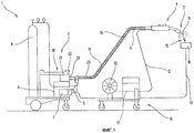
на фиг.1 - сварочный аппарат для осуществления способа электродуговой сварки;figure 1 - welding machine for implementing the method of electric arc welding;
на фиг.2 - электрическая схема сварочной цепи сварочного аппарата 1 в связи с изделием, подлежащим сварке;figure 2 - electrical diagram of the welding circuit of the
на фиг.3а, b - схематично представленная временная диаграмма сварочного напряжения для процесса дуговой сварки в определенный момент времени и другая соответственная диаграмма в другой более поздний момент времени процесса сварки;on figa, b is a schematic diagram of the time diagram of the welding voltage for the arc welding process at a certain point in time and another corresponding diagram at another later point in time of the welding process;
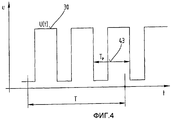
на фиг.4 - схематично представленная временная диаграмма сварочного напряжения U(t) для процесса дуговой сварки;figure 4 - schematically shows a timing diagram of the welding voltage U (t) for the arc welding process;
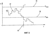
на фиг.5 - временная диаграмма частоты H(t) возникновения коротких замыканий согласно фиг.4;figure 5 is a timing chart of the frequency H (t) occurrence of short circuits according to figure 4;
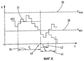
на фиг.6 - диаграмма частоты H(t) другого примера осуществления способа сварки;6 is a frequency diagram H (t) of another example embodiment of a welding method;
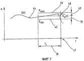
на фиг.7 - временная диаграмма мгновенного сопротивления R(t) электрической дуги;7 is a timing diagram of the instantaneous resistance R (t) of the electric arc;
на фиг.8 - временная диаграмма сварочного тока I(t) при процессе импульсной сварки;on Fig is a timing diagram of the welding current I (t) during the pulse welding process;
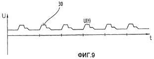
на фиг.9 - временная диаграмма сварочного напряжения U(t), соответствующая процессу импульсной сварки;figure 9 is a timing diagram of the welding voltage U (t) corresponding to the pulse welding process;
на фиг.10 - диаграмма изменяющейся во времени кривой мгновенного сопротивления R(t) электрической дуги;figure 10 is a diagram of a time-varying curve of the instantaneous resistance R (t) of an electric arc;
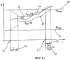
на фиг.11 - временная диаграмма мгновенного сопротивления R(t) электрической дуги с изменяющимися во времени верхней и нижней границами и неизменяющимися во времени верхней и нижней границами.11 is a timing diagram of the instantaneous resistance R (t) of an electric arc with time-varying upper and lower boundaries and time-unchanging upper and lower boundaries.
В качестве введения следует установить, что в различно описанных примерах выполнения одинаковые элементы снабжены одними и теми же ссылочными номерами или обозначениями, причем раскрытая информация, содержащаяся в описании, может быть перенесена на одинаковые элементы с одними и теми же ссылочными номерами или обозначениями. Кроме того, выбранные в описание сведения о положении, такие как, например, верхний (вверху), нижний (внизу), боковой (сбоку) и т.д., относятся к непосредственно описанной и представленной фигуре и при изменении положения должны переноситься на новое положение. Кроме того, отдельные признаки или комбинации признаков из показанных и описанных различных вариантов осуществления изобретения могут также, по сути, представлять собой самостоятельные технические решения согласно изобретению, имеющие изобретательский уровень.As an introduction, it should be established that in the variously described exemplary embodiments, the same elements are provided with the same reference numbers or symbols, and the disclosed information contained in the description can be transferred to the same elements with the same reference numbers or symbols. In addition, positional information selected in the description, such as, for example, top (top), bottom (bottom), side (side), etc., refers to the figure directly described and presented and, when changing position, should be transferred to a new position. In addition, individual features or combinations of features from the shown and described various embodiments of the invention can also, in fact, constitute independent technical solutions according to the invention having an inventive step.
На фиг.1 и 2 показана сварочная установка, в частности сварочный аппарат 1 для осуществления процесса или способа электродуговой сварки, такой как, например, МИГ/МАГ сварка (плавящимся электродом в инертном/активном газе) или импульсная сварка. Сварочный аппарат 1 содержит источник 2 тока с силовой частью 3 и устройством 4 управления. Устройство 4 управления связано с клапаном 5 управления. Клапан 5 управления расположен в линии 6 снабжения газом 7 между газовым накопителем 8 и сварочной горелкой 9. Что касается газа 7, то речь идет, в частности, о защитном газе, таком как, например, CO2, гелий, аргон и тому подобное.Figures 1 and 2 show a welding installation, in particular a
Далее, посредством устройства 4 управления может осуществляться управление подающим устройством 10 для сварочной проволоки 11. При этом сварочная проволока 11 подается по линии 13 снабжения от накопительного барабана 13 в область сварочной горелки 9. Само собой разумеется, подающее устройство 10 может быть, как это известно из уровня техники, также встроено в сварочный аппарат 1.Further, by means of the
По линии 14 снабжения от силовой части 3 источника 2 тока к сварочной горелке 9 и, соответственно, сварочной проволоке 11 подают ток для создания электрической дуги 15 между сварочной проволокой 11 и обрабатываемым изделием 16. При этом свариваемое изделие 16 посредством другой линии 17 снабжения также соединено со сварочным аппаратом 1 и, соответственно, с источником 2 тока, таким образом посредством электрической дуги 15 может быть создана замкнутая электрическая цепь.On the
Сварочный аппарат 1 может быть снабжен устройством 18 охлаждения, причем по контуру 19 охлаждения с промежуточным включением датчика 20 потока и, соответственно, гидравлического насоса к сварочной горелке 9 может подаваться жидкость из резервуара 21 для охлаждающего средства.The
Для установки (регулирования) различных режимов работы, в частности соответствующих параметров сварки, на сварочном аппарате 1 предусмотрено устройство 22 ввода и/или вывода. Режимы работы или, соответственно, параметры сварки, установленные посредством устройства 22 ввода и/или вывода, передаются далее к устройству 4 управления, посредством которого затем регулируются отдельные компоненты сварочной установки или сварочного аппарата 1.To install (control) various operating modes, in particular the corresponding welding parameters, an input and / or
Отдельные линии, соединяющие сварочный аппарат 1 со сварочной горелкой 9, расположены в шланговом пакете 23 протянутыми в нем или связанными в нем в пучки.Separate lines connecting the
На фиг.2 показана электрическая схема сварочной цепи или, соответственно, сварочного аппарата 1 в связи со свариваемым изделием 16.Figure 2 shows the electrical circuit of the welding circuit or, respectively, of the
Отдельные компоненты силовой части 3 или, соответственно, источника 2 тока, а также устройство 4 управления встроены в сварочный аппарат 1. Посредством линий 14, 17 снабжения источник 2 тока соединен со сварочной горелкой 9 и, соответственно, обрабатываемым изделием 16. С другой стороны устройство 4 управления соединено посредством линии 24 управления также с подающим устройством, и таким образом может осуществляться автоматизированное управление подающим устройством 10 или, соответственно, подачей сварочной проволоки 11. Посредством привода 25 и соединенных с ним подающих роликов 26, 27 может осуществляться управление скоростью «Vd» подачи сварочной проволоки 11.The individual components of the
При осуществлении способа согласно изобретению предусматривают контроль электрических параметров (величин) сварочной цепи. Для этого устройство 4 управления содержит измерительное устройство 28, с помощью которого могут быть замерены мгновенные значения сварочного тока I(t) 29 и сварочного напряжения U(t) 30. Измерительное устройство 28 соединено посредством измерительных линий 31, 32 с выходными клеммами 33, 34 источника 2 тока; таким образом может быть измерено напряжение UK(t) на клеммах. Пренебрегая сопротивлением или импедансом линий 14, 17 снабжения сварочной цепи, вместо сварочного напряжения U(t) может быть использовано напряжение UK(t) на клеммах, и тем самым не требуется проведение измерительных линий 31, 32 до сварочной горелки 9 и, соответственно, обрабатываемого изделия 16 (показано штрихованной линией). Однако в качестве альтернативы сварочное напряжение U(t) 30 может быть также замерено напрямую посредством замыкания контактов измерительных линий 31, 32 на сварочной горелке 9 и, соответственно, обрабатываемом (свариваемом) изделии 15.When implementing the method according to the invention provide for the control of electrical parameters (values) of the welding circuit. To this end, the
С помощью фиг.3 описывается первый пример осуществления способа согласно изобретению. При этом показана временная диаграмма (эпюра) сварочного напряжения U(t) 30 для нормального процесса электродуговой сварки, в то время как на фиг.4 и 5 описан процесс электродуговой сварки с так называемой короткой дугой.3, a first embodiment of a method according to the invention is described. In this case, a time diagram (diagram) of the welding voltage U (t) 30 for the normal process of electric arc welding is shown, while FIGS. 4 and 5 describe the process of electric arc welding with the so-called short arc.
В случае временной диаграммы сварочного процесса согласно фиг.3 описано сварочное напряжение 30 до момента времени, схематично показанного штрихпунктирной линией, в соответствии со значением параметра 100, измеренным в данный момент времени измерительным устройством 28. Далее, кривая сварочного напряжения 30, следующая непосредственно после данного момента времени, для лучшего понимания показана на диаграмме штриховой линией. В принципе, следует упомянуть, что определению «параметр 100» соответствует полученное измерительным устройством или расчетным путем значение одного или нескольких сварочных параметров, таких как сварочное напряжение, сварочный ток, сопротивление, мощность и т.д., и в качестве примера для рассматриваемого варианта осуществления изобретения на фиг.3 применяется сварочное напряжение 30.In the case of a timing diagram of the welding process according to FIG. 3,
При этом на обеих диаграммах согласно фиг.3 показан один и тот же сварочный процесс, однако в разный момент времени, т.е. сварочный процесс имел отличную протяженностью по времени, чем обозначено мгновенным параметром 100.At the same time, both diagrams according to Fig. 3 show the same welding process, however, at different times, i.e. the welding process had an excellent length in time than indicated by the instant parameter 100.
При способе согласно изобретению предусмотрено, что устанавливают первый временной интервал 101 и второй временной интервал 102, а также частоту 103 выборки, показанную схематично стрелками, для определения параметра 100, т.е. посредством устройства 4 управления при приведении сварочного аппарата 1 в действие устанавливают продолжительность интервалов 101 и 102, а также частоту 103 (дискретность) выборки, с которой должно осуществляться определение параметров 100. Кроме этого, данные могут сохраняться в запоминающем устройстве и/или устанавливаться или изменяться пользователем. При этом является существенным, что продолжительность временных интервалов 101 и 102 значительно отличается, причем первый временной интервал 101 длиннее второго временного интервала. При этом первый временной интервал может продолжаться, например, 0,5 секунд, а второй временной интервал 0,1 секунду. Частота 103 выборки может, например, составлять 20 кГц. Первый временной интервал имеет предпочтительно продолжительность от 0,3 до 1 секунд, а второй временной интервал от 0,05 до 0,3 секунд.In the method according to the invention, it is provided that a first time interval 101 and a second time interval 102, as well as a sampling frequency 103, shown schematically by arrows, are set to determine parameter 100, i.e. by means of the
Как только процесс сварки начался и соответствующая начальная фаза (период запуска) для стабилизации процесса завершилась, посредством устройства 4 управления или, соответственно, измерительным устройством 28 в каждый момент времени согласно частоте 103 выборки (стрелки на фиг.3) определяют значение параметра 100, т.е. по установленной частоте 103 выборки осуществляют постоянное определение параметра 100 и его сохранение (запоминание). Однако для управления сварочным процессом устройство 4 управления всегда учитывает лишь то сохраненное значение параметра 100 для дальнейшего расчета, которое имеет более раннее расположение по времени относительно мгновенного значения параметра 100 в пределах временных интервалов 101 и 102. Дополнительное, заранее определенное значение параметра 100, хотя и может быть сохранено, например, для проверки качества, однако не является необходимым для способа регулирования согласно изобретению. Таким образом получается, что временные интервалы 101 и 102 привязаны к мгновенному, т.е. текущему параметру 100, и что временные интервалы 101 и 102, или, соответственно, содержащиеся в них измеренные параметры 100, перемещаются во время процесса сварки вместе с мгновенным параметром 100. Это видно из обеих диаграмм, представленных на фиг.3, поскольку мгновенные параметры 100 показаны в различные моменты времени сварки, причем временные интервалы 101 и 102 перемещаются в соответствии с дальнейшим прохождением процесса сварки по времени вместе с ними. В результате этого расположенные во временных интервалах 101 и 102 значения параметра 100 или, соответственно, количество содержащихся в них значений постоянно изменяется, поскольку всегда добавляется самый новый параметр 100 и тем самым из временного интервала 101 и 102 выпадает самый старый параметр 100.As soon as the welding process has begun and the corresponding initial phase (start-up period) to stabilize the process is completed, by means of the
После того как, а именно после начала процесса сварки, начальная фаза заканчивается и, соответственно, определено большое количество отдельных значений параметра 100 для временного интервала 101 и 102, посредством устройства 4 управления по данным значениям параметра 100, лежащим в пределах временных интервалах 101 и 102, вычисляют первое среднее значение 106 для первого временного интервала 101 и второе среднее значение 107 для второго временного интервала 102. Затем на основе первого среднего значения 106 первого временного интервала 101 вычисляют верхнее и нижнее предельные значения 104 и 105. Второе среднее значение 107 второго временного интервала 102 используют в качестве контрольной величины, с которой сравнивают верхнее и нижнее предельные значения 104 и 105. При этом предпочтительно, если предельные значения 104 и 105 расположены по возможности близко к первому среднему значению 106, т.е. от среднего значения 106 берется 10% в сторону повышения и, соответственно, понижения, так что устанавливают как можно более узкую область допуска. При этом возможно, чтобы определение или расчет предельных значений 104 и 105 производился по-разному в зависимости от других установленных параметров сварки, например в зависимости от свариваемого материала, от сварочной проволоки и т.д.After, namely, after the start of the welding process, the initial phase ends and, accordingly, a large number of individual values of the parameter 100 are determined for the time interval 101 and 102, by means of the
За счет различной длины или, соответственно, длительности временных интервалов 101 и 102 они имеют различное количество значений параметра 100, так что образуются соответственно различные средние значения 106, 107. При этом также возможно, что длительность временного интервала 102 выбрана настолько короткой, что в нем находится только одно единственное значение параметра 100, так что регулирование осуществляется с помощью последнего полученного значения параметра 100, которое в то же самое время образует контрольную величину.Due to the different length or, accordingly, the duration of the time intervals 101 and 102, they have a different number of parameter values 100, so that different average values 106, 107 are formed, respectively. It is also possible that the duration of the time interval 102 is chosen so short that only one single value of parameter 100 is found, so that regulation is carried out using the last obtained value of parameter 100, which at the same time forms a control value.
Таким образом, посредством такого способа регулирования с помощью первого временного интервала 101, в котором содержится несколько замеренных значений одного или более параметров 100, достигают того, что предельные значения 104 и 105 для контроля характера кривой контролируемого параметра 100 могут находиться очень близко к данному параметру 100, т.е. соответствующему параметру сварки, и тем самым может устанавливаться очень быстрое изменение характера кривой параметра 100 (параметра сварки).Thus, by such a control method using the first time interval 101, which contains several measured values of one or more parameters 100, it is achieved that the limit values 104 and 105 for controlling the nature of the curve of the controlled parameter 100 can be very close to this parameter 100 , i.e. corresponding welding parameter, and thereby a very rapid change in the nature of the curve of parameter 100 (welding parameter) can be established.
Использование второго временного интервала 102 для сравнения параметра 100 с рассчитанным предельным параметром 101 и 102 имеет преимущество потому, что во время сварки часто случаются кратковременные изменения состояния процесса, такие как, например, из-за посторонних включений в обрабатываемом изделии 16 и т.д., которые вызывают кратковременное изменение параметра 100, однако не имеют значительного влияния на процесс. Т.е. если используется только последнее полученное значение параметра 100, то он изменяется часто и переходит в этом случае предельное значение 101 и 102, в результате чего устройство 4 управления запускает операцию, которая, собственно говоря, не являлась бы необходимой. Для того чтобы это не происходило постоянно, в регулировочный процесс вводится второй временной интервал 102 с существенно более короткой продолжительностью, так что, в свою очередь, может использоваться среднее значение 107 для сравнения с предельными значениями 101 и 102, и, таким образом, кратковременные, сильные изменения не имеют моментального влияния.Using the second time interval 102 to compare parameter 100 with the calculated limit parameter 101 and 102 is advantageous because short-time changes in the process state often occur during welding, such as, for example, due to foreign impurities in the
Также возможно, что в качестве эквивалентного варианта вместо первого и второго временных интервалов 101 и 102 применяется избирательное количество значений параметра 100, т.е., например, первое количество состоит из 1000 значений параметра 100, а второе количество состоит из 10 значений параметра 100, из которых потом образуются средние значения 106, 107. Это может быть образовано простым образом, например по типу сдвигового регистра, в котором всегда прибавляются последние полученные значения параметра 100, за счет чего лежащие по времени наиболее далеко позади значения параметра 100 выпадают. Также возможно, что такая процедура может осуществляться с помощью известного из уровня техники запоминающего устройства, так называемого устройства, работающего по принципу «First-In Last-Out» (первый принят - последний вышел).It is also possible that, as an equivalent option, instead of the first and second time intervals 101 and 102, a selective number of parameter values of 100 is used, i.e., for example, the first number consists of 1000 values of parameter 100, and the second number consists of 10 values of parameter 100, from which average values 106, 107 are then formed. This can be formed in a simple way, for example, according to the type of shift register, in which the last obtained values of parameter 100 are always added, due to which the most to the back of the parameter value 100 falls. It is also possible that such a procedure can be carried out using a memory device known from the prior art, a so-called device operating on the principle of “First-In Last-Out” (the first is accepted - the last is out).
Таким образом, при таком способе регулирования можно сказать, что из определенного количества полученных данных касательно сварочного процесса получают средние значения 106, 107, причем из первого среднего значения 106, полученного из значительно большего количества значений, рассчитывают предельные значения 104 и 105, которые лежат как можно более близко к первому среднему значению 106, после чего указанные предельные значения 104 и 105 сравнивают со вторым средним значением 107, полученным из значительно меньшего количества значений. При этом такое создание средних значений может осуществляться из самых различных параметров сварки, таких как, например, короткие замыкания, сварочный ток, сварочное напряжение, рассчитанное или замеренное напряжение, рассчитанная или замеренная мощность и т.д.Thus, with this control method, we can say that from a certain amount of data obtained regarding the welding process, average values 106, 107 are obtained, and from the first average value 106 obtained from a much larger number of values, the limit values 104 and 105 are calculated, which lie as can be closer to the first average value 106, after which the specified limit values 104 and 105 are compared with the second average value 107 obtained from a significantly smaller number of values. Moreover, such a creation of average values can be carried out from a variety of welding parameters, such as, for example, short circuits, welding current, welding voltage, calculated or measured voltage, calculated or measured power, etc.
Далее дается более подробное описание описанного ранее лишь схематично способа в виде примеров на следующих фигурах.The following is a more detailed description of the previously described only schematically method in the form of examples in the following figures.
С помощью фиг.4 и 5 дается описание другого варианта осуществления способа сварки согласно изобретению. На фиг.4 в виде временной диаграммы показана кривая сварочного напряжения U(t) 30 для процесса электродуговой сварки с так называемой короткой дугой. При таком виде сварки за счет расплавления сварочной проволоки 11 в электрической дуге 15 происходит образование жидкой металлической капли, которая при отделении от сварочной проволоки 11 кратковременно создает между сварочной проволокой 11 и обрабатываемым изделием 16, или, соответственно, ванной жидкого металла на обрабатываемом изделии, короткое электрическое замыкание, в результате чего сварочное напряжение U(t) 30 при коротком замыкании, т.е. на время короткого замыкания, сильно падает. Как только металлическая капля полностью отделится от сварочной проволоки 11 и соединится с обрабатываемым изделием 16, или, соответственно, со сварным швом, сварное напряжение U(t) 30 снова повышается. Таким образом получается периодичная последовательность низких и высоких значений сварочного напряжения U(t) 30 с показанным на фиг.4 упрощенно периодичным характером кривой сварочного напряжения U(t) 30. При этом короткие замыкания можно видеть по кривой сварочного напряжения U(t) 30 с низкими значениями. Стабильный ход процесса сварки имеет остающееся примерно одинаковым количество коротких замыканий в течение временного интервала T. Однако в реальных сварочных процессах указанное количество колеблется в зависимости от времени.Using FIGS. 4 and 5, another embodiment of a welding method according to the invention is described. In Fig. 4, a time diagram of a welding voltage curve U (t) 30 is shown for an electric arc welding process with a so-called short arc. In this type of welding, due to the melting of the
На фиг.5 показана временная диаграмма кривой частоты H(t) 37 возникновения коротких замыканий в течение временного интервала T согласно фиг.4.FIG. 5 is a timing chart of a frequency curve H (t) 37 of occurrence of short circuits during a time interval T of FIG. 4.
В устройстве 4 управления сварочного аппарата 1 непрерывно регистрируются мгновенные значения изменяемой во времени частоты H(t) 37 возникновения коротких замыканий, за счет чего может контролироваться сварочный процесс. Для этого в устройстве 4 управления, или в контрольном модуле, реализованном в нем согласно программному обеспечению, сохраняется минимальная частота Hmin 38 в качестве нижней границы и максимальная частота Hmax 39 в качестве верхней границы, а устройство 4 управления постоянно осуществляет сравнивание мгновенных частот H(t) 37 с указанными верхней и нижней границами. Значения для указанных границ, т.е. минимальная частота Hmin 38 и, соответственно, максимальная частота Hmax 39, могут быть выведены из эмпирических величин или пробных сварочных операций.In the
С помощью показанной на фиг.5 временной диаграммы кривой частоты H(t) 37 ход контроля процессом сварки посредством устройства 4 управления должен быть пояснен более подробно. Для временных значений, лежащих перед моментом 40 времени, значения частоты H(t) 37 находятся между минимальной частотой Hmin 38 и максимальной частотой Hmax 39, и сварочный процесс для временного интервала, лежащего до момента 40 времени, классифицируется как правильный или бесперебойный. В последней фазе указанного временного отрезка частота H(t) 37 еще больше уменьшается и, в конце концов, переходит в момент 40 времени значение минимальной частоты Hmin 38, и данное событие классифицируется устройством 4 управления как наличие сбоя (неисправности) в сварочном процессе, после чего устройство 4 управления формирует контрольный сигнал. Сбой, установленный устройством 4 управления в момент 40 времени, может состоять, например, в том, что скорость Vd подачи сварочной проволоки 11 слишком упала, т.е. она значительно не достигает своей заданной величины. Создаваемый устройством 4 управления контрольный сигнал может использоваться в качестве пускового сигнала для различных вызванных устройством 4 управления ответных мер. Инициированный контрольным сигналом, например, привод 25 подающего устройства 10 регулируется посредством устройства 4 управления таким образом, что скорость Vd подачи сварочной проволоки 11 увеличивается, так что частота H(t) 37 снова принимает значение, лежащее между минимальной частотой Hmin 38 и максимальной частотой Hmax 39. Однако другой причиной для снижения частоты H(t) 37 ниже минимальной частоты Hmin 38 может быть также то, что произошло заклинивание или блокирование сварочной проволоки 11 в сварочной горелке 9 или контактной трубе сварочной горелки 9, или так называемое обратное горение сварочной проволоки 11, что приводит к свариванию сварочной проволоки с контактной трубой сварочной горелки 9. Устройство 4 управления может быть запрограммировано таким образом, что на основании выданного контрольного сигнала сварочный процесс прерывается, во время чего сварочный ток I(t) 29 и, соответственно, сварочное напряжение U(t) 30 отключаются, а привод 25 подающего устройства 10 останавливается.Using the time diagram of the frequency curve H (t) 37 shown in FIG. 5, the progress of the welding process control by the
Конечно, может случиться так, что частота H(t) перейдет верхнюю границу значения максимальной частоты Hmax 39, что показано на фиг.5 штриховой линией. Тогда можно, например, путем увеличения скорости Vd подачи сварочной проволоки 11 за счет слишком большого превышения своего заданного значения настолько увеличить мгновенную частоту H(t) 37, что произойдет полное затухание электрической дуги 25 и создание продолжительного короткого замыкания между сварочной проволокой 11 и обрабатываемым изделием 16. Таким образом предусмотрено, что устройство 4 управления при превышении верхней границы, т.е. значения максимальной частоты Hmax 39, в свою очередь, выдает контрольный сигнал. Затем на основании данного контрольного сигнала устройство 4 управления регулирует привод 25 подающего устройства 10 таким образом, что скорость Vd подачи сварочной проволоки 11 понижается до своего заданного значения.Of course, it can happen that the frequency H (t) goes over the upper limit of the maximum
На фиг.6 на временной диаграмме кривой частоты H(t) 37 показан другой пример осуществления способа сварки.6, a timing diagram of a frequency curve H (t) 37 shows another example embodiment of a welding method.
В альтернативном варианте осуществления описанного способа может быть также предусмотрено, что верхнее и нижнее предельные значения для частоты H(d) 37, т.е. максимальные частоты Hmax(t) 39 и минимальные частоты Hmin(t) 38 образованы предельными значениями, изменяющимися во времени. Для этого по меньшей мере в течение заданного временного интервала TI 36 (соответствует первому временному интервалу 101) регистрируют и, соответственно, сохраняют в устройстве 4 управления значения контрольных величин, т.е. значения частоты H(t) 37. С использованием тех значений, которые лежат именно в данном временном интервале TI 36, сначала рассчитывают среднее значение (соответствует первому среднему значению 106 согласно фиг.3) контрольной величины и на основании его рассчитывают верхнее и нижнее предельные значения (соответствуют предельным значениям 104 и 105), т.е. устанавливают максимальную частоту Hmax(t) 39 и минимальную частоту Hmin(t) 38. В отличие от неизменяемых во времени предельных значений изменяемые по времени верхние и нижние предельные значения 104 и 105 для контрольной величины частоты H(t) 37 имеют то преимущество, что они могут быть использованы очень гибко, а область между предельными значениями 104 и 105 может быть выбрана очень узкой. Относительно среднего значения контрольной величины предельные значения 104 и 105 имеют разность, которая составляет только небольшую часть среднего значения контрольной величины. Для контроля сварочного процесса предусмотрено, что после превышения верхнего или после понижения нижнего предельных значений 104 и 105 посредством мгновенного значения частоты H(t) 37 устройством 4 управления выдается контрольный сигнал. Затем в зависимости от контрольного сигнала устройством 4 управления генерируется прерывание сварочного процесса или же сообщение о состоянии (режимах) сварочного процесса или, соответственно, отдельных компонентов сварочной установки. За счет этого особенно предпочтительным образом можно избежать повреждения сварочной установки из-за так называемого обратного сжигания сварочной проволоки. Для этого в зависимости от контрольного сигнала соответствующим образом изменяется регулирование скорости подачи подающего устройства 10 для сварочной проволоки 11. Для получения изменяющихся по времени верхнего и нижнего предельных значений 104 и 105 для контрольной величины осуществляют постоянный непрерывный во времени перерасчет как среднего значения контрольной величины, так и выведенных из него верхнего и нижнего предельных значений 104 и 105. Лежащий перед мгновенным значением контрольной величины временной интервал TI 36 (соответствует первому временному интервалу 101) образует таким образом временное окно для выбора тех значений контрольной величины, которые привлекаются для расчета или, соответственно, перерасчета верхних и нижних предельных значений 104 и 105. Таким образом, временной интервал TI 36 в некоторой мере перемещается во времени. При этом предпочтительно, если соответствующее расположение временного интервала TI 36 во времени выбирается непосредственно впереди идущим перед соответственно последним полученным значением контрольной величины.In an alternative embodiment of the described method, it may also be provided that the upper and lower limit values for the frequency H (d) 37, i.e. the maximum frequencies Hmax (t) 39 and the minimum frequencies Hmin (t) 38 are formed by limit values that vary with time. For this, at least for a given time interval, TI 36 (corresponds to the first time interval 101) is recorded and, accordingly, the values of control values are stored in the
Кроме этого, в устройстве 4 управления, помимо нижней и верхней границы для частоты H(t), запоминают также значение контрольного времени TK 41. Если частота H(t) 37 понижается ниже минимальной частоты Hmin 38 в момент 40 времени, устройство 4 управления начинает измерение времени TB 42 наблюдения, которое длится столько, сколько времени мгновенное значение частоты H(t) 37 находится ниже минимальной частоты Hmin 38. Пока указанное время TB 42 наблюдения меньше заранее установленного контрольного времени TK 41, сварочный процесс еще классифицируется устройством 4 управления как стабильный или правильный. Т.е. если значение мгновенной частоты H(t) 37 снова станет выше значения минимальной частоты Hmin 38 и, соответственно, будет меняться в области минимальной частоты Hmin 38 и максимальной частоты Hmax 38, устройство 4 управления не выдаст контрольного сигнала (показанная однородной кривая частоты H(t)). Напротив, если мгновенная частота H(t) 37 после понижения ниже минимальной частоты Hmin 38 в момент 40 времени в течение времени TB 42 наблюдения, которое длится дольше контрольного времени TK 41, остается ниже минимальной частоты Hmin 38, то устройством 4 управления выдается контрольный сигнал (показанная штриховой кривая частоты H(t)). Впоследствии на основании данного контрольного сигнала посредством устройства 4 управления принимаются различные меры. Ими могут быть, например, соответствующие ответные меры посредством регулирования подающего устройства 10, как было приведено ранее, а также регулирования других компонентов сварочного аппарата посредством устройства 4 управления, таких как, например, устройство 18 охлаждения, или же только инициирование сигнала тревоги, т.е. полной остановки сварочного процесса.In addition, in the
Далее с помощью фиг.4 может быть описан еще один альтернативный вариант осуществления способа сварки согласно изобретению с контролем сварочного процесса. При этом предусмотрено, что вместо частоты H(t) 37 в качестве контрольной величины используют период TP 43, соответствующий временному интервалу между двух следующих друг за другом коротких замыканий или, соответственно, минимумов на временной диаграмме сварочного напряжения U(t) 30. Так же как и временная кривая H(t) 37, посредством устройства 4 управления записывают временную кривую, или другими словами, изменения периода TP 43, и устройство 4 управления проводит непрерывное сравнивание с нижней и верхней границами для периода TP 43. Таким образом, при превышении максимального значения, или верхней границы периода TP 43, устройством 4 управления может быть также выдан контрольный сигнал. Превышение верхней границы периода 43 соответствует, в частности, понижению мгновенной частоты H(t) 37 ниже минимальной частоты Hmin 38, и в целом устройством 4 управления предусмотрены аналогичные меры по регулированию, какие были описаны ранее в отношении частоты H(t) 37.Further, with the help of FIG. 4, another alternative embodiment of the welding method according to the invention with monitoring of the welding process can be described. It is provided that instead of the frequency H (t) 37, the
При использовании периода TP 43 в качестве контрольной величины для контроля сварочного процесса в периодическом характере кривой сварочного напряжения U(t) 30 путем анализа постоянно записываемой кривой сварочного напряжения U(t) 30 определяют минимумы, т.е., в частности, происходящие короткие замыкания, на основании чего рассчитывают периоды TP 43 между соответственно двумя следующими друг за другом минимумами. На основании превышения верхнего или после понижения ниже нижнего предельного значения 104 и 105 для периода TP 43 устройство 4 управления выдает контрольный сигнал, после чего в зависимости от контрольного сигнала посредством устройства 4 управления сварочный процесс прерывается или генерируется сообщение о состоянии. Предпочтительно превышение верхнего предельного значения 104 или 105 для периода TP 43 является поводом для прерывания сварочного процесса, поскольку наиболее вероятной причиной этому является «обратное сжигание проволоки». Как ранее уже было описано в отношении частоты H(t) 37, здесь также возможно использование изменяемых во времени верхнего и нижнего предельных значения 104 и 105 для периода TP 43.When using the
При помощи фиг.7-10 описывается вариант осуществления способа сварки с использованием мгновенного сопротивления R(t) 44 электрической дуги 15, т.е. измеряют сварочное напряжение и сварочный ток и по ним рассчитывают сопротивление R(t) 44 в качестве параметра 100. На фиг.7 показана временная диаграмма кривой сопротивления R(t) 44, как оно получается путем вычисления согласно закону Ома из сварочного напряжения U(t) 30 и сварочного тока I(t) 29. Для контроля сварочного процесса в данном способе устройством 4 управления осуществляется постоянного сравнение мгновенного сопротивления R(t) 44 с минимальным сопротивлением Rmin 45 (соответствует нижнему предельному значению 105 для первого временного интервала 101) и максимальным сопротивлением Rmax 46 (соответствует верхнему предельному значению 104 для первого временного интервала 101). После превышения мгновенным сопротивлением R(t) 44 (соответствует среднему значению параметра сопротивления для второго временного интервала 102) максимального сопротивления Rmax 46 или, соответственно, его понижения ниже минимального сопротивления Rmin 45 устройством 4 управления, как уже было ранее описано, выдается контрольный сигнал.Using FIGS. 7-10, an embodiment of a welding method using the instantaneous resistance R (t) 44 of an
Согласно данному примеру осуществления значения минимального сопротивления Rmin 45 и максимального сопротивления Rmax 46 устанавливаются не на абсолютные, жестко заданные значения, а зависят от кривой зависимости сопротивления R(t) 44 от времени. Для этого в каждый мгновенный момент 47 времени рассчитывают среднее сопротивление RM(t) 48 по временному интервалу TI 36, непосредственно предшествующему мгновенному моменту 47 времени. За счет записи, т.е. сохранения, отдельных значений сопротивления R(t) 44 в устройстве 4 управления имеется, соответственно, определенное продолжительностью временного интервала TI 36 количество отдельных значений для расчета указанного среднего значения. Нижняя, а также верхняя граница для сопротивления R(t) 44 является таким образом также зависимой от времени, т.е. изменяемой во времени. Максимальное сопротивление Rmax(t) 46 определяется таким образом от сопротивления RM(t) 48 посредством прибавления верхней разности Reo 49 сопротивления, а минимальное сопротивление Rmin(t) 45 определяется от среднего сопротивления RM(t) 48 посредством вычитания нижней разности Reu 50 сопротивления. Таким образом, как и среднее сопротивление RM(t) 48, значения минимального сопротивления Rmin(t) 45 и максимального сопротивления Rmax 46 непрерывно регистрируются устройством 4 управления для контроля сварочного процесса, причем устройством 4 управления устанавливается, превысило ли верхнюю границу или опустилось ниже нижней границы мгновенное сопротивление R(t) 44. Если это произошло, устройством 4 управления может быть выдан контрольный сигнал, на основании которого дополнительные действия отдельных компонентов сварочного аппарата могут быть запущены соответствующими управляющими командами устройства 4 управления. В качестве примера это показано на фиг.7 посредством понижения ниже минимального сопротивления Rmin(t) 46 в момент 47 времени посредством показанной штриховой линией временной кривой сопротивления R(t) 44.According to this embodiment, the values of the
Использование описанных изменяемых во времени предельных значений 104 и 105 для нижней и верхней границ контрольной величины позволяет, с одной стороны, очень гибко применять способ, и, с другой стороны, очень быстро реагировать на внезапно возникшие изменения в сварочном процессе или во время эксплуатации сварочного аппарата. Именно за счет одновременного ведения во времени верхнего и нижнего предельных значений 104 и 105 в зависимости от средней контрольной величины становится возможным расположить их в очень узком диапазоне около мгновенного прохождения контрольной величины, т.е. мгновенного сопротивления R(t) 44 (ко второму временному интервалу 102). Разность предельных значений 104 и 105 к среднему значению может предпочтительным образом быть выбрана в пределах менее 1% от мгновенного сопротивления R(t) 44. При этом предусмотрено, что длительность временного интервала TI 36 (первого временного интервала 101) имеет значение менее одной секунды.Using the described time-varying limit values 104 and 105 for the lower and upper boundaries of the control value allows, on the one hand, the method to be used very flexibly and, on the other hand, to respond very quickly to sudden changes in the welding process or during operation of the welding machine . It is due to the simultaneous time management of the upper and lower limit values 104 and 105, depending on the average control value, that it becomes possible to arrange them in a very narrow range near the instantaneous passage of the control value, i.e. instantaneous resistance R (t) 44 (to the second time interval 102). The difference between the limiting values 104 and 105 to the average value can preferably be selected within less than 1% of the instantaneous resistance R (t) 44. It is hereby provided that the duration of the time interval TI 36 (first time interval 101) is less than one second.
Описанный здесь пример выполнения с использованием мгновенного сопротивления R(t) 44 в качестве контрольной величины для контроля сварочного процесса особенно подходит, например, для применения при сварке со струйным переносом металла через дугу или при импульсной сварке, а также при электродуговой сварке с управляемым возвратно-поступательным осциллирующим движением сварочной проволоки 11.The embodiment described here, using the instantaneous resistance R (t) 44 as a control value for controlling the welding process, is particularly suitable, for example, for use in welding with jet transfer of metal through an arc or in pulsed welding, as well as in electric arc welding with controlled reciprocating translational oscillating movement of the
На фиг.8 и 9 показана в качестве примера временная диаграмма сварочного тока I(t) 29 (фиг.8) и сварочного напряжения U(t)30 (фиг.9). При этом предпочтительно предусмотрено, что вместо контрольной величины сопротивления R(t) 44 используют среднее значение по меньшей мере за один период TP 43 импульса. Данное усреднение соответствует второму среднему значению 107 для второго временного интервала 102 согласно описанию к фиг.3. Преимуществом этого является то, что избегают чрезмерных колебаний во временной характеристике сопротивления R(t) 44 (фиг.7), поскольку для контроля сварочного процесса они являются малозначительными.Figures 8 and 9 show, by way of example, a timing diagram of the welding current I (t) 29 (Fig. 8) and the welding voltage U (t) 30 (Fig. 9). In this case, it is preferably provided that instead of the reference resistance value R (t) 44, an average value for at least one
Альтернативно этому можно для расчета сопротивления R(t) 44 также использовать, например, значения сварочного тока I(t) 29 или сварочного напряжения U(t) 30 из импульсной фазы, т.е. использовать соответственно максимальные значения кривых сварочного тока или сварочного напряжения.Alternatively, for calculating the resistance R (t) 44, one can also use, for example, the values of the welding current I (t) 29 or the welding voltage U (t) 30 from the pulse phase, i.e. use respectively the maximum values of the welding current or welding voltage curves.
С помощью фиг.10 далее поясняется еще один пример осуществления способа согласно изобретению с использованием сопротивления R(t) 44 в качестве контрольной величины для контроля сварочного процесса. В случае если мгновенное сопротивление R(t) 44 опускается ниже минимального сопротивления Rmin 45 в момент 47 времени, то устройство 4 управления начинает измерение времени TB 42 наблюдения. Это происходит, пока мгновенное сопротивление R(t) 44 находится ниже минимального сопротивления Rmin 45. Пока указанное время TB 42 наблюдения меньше заданного контрольного времени TK 41, сварочный процесс классифицируется устройством 4 управления как стабильный или нормальный. Если мгновенное сопротивление R(t) 44 возвращается в область между минимальным сопротивлением Rmin 45 и максимальным сопротивлением Rmax 46 до истечения контрольного времени TK 41, то контрольный сигнал не выдается устройством 4 управления. При этом в качестве нижней и верхней границ используют те значения минимального сопротивления Rmin(t) 45 и, соответственно, максимального сопротивления Rmax(t) 46, которые получились в момент 47 времени на основании среднего сопротивления RM(t) 48. В качестве альтернативы этому возможен также постоянный перерасчет среднего сопротивления RM(t) 48 также в течение контрольного времени TK 41 и, таким образом, соответствующее изменение нижней и верхней границы 45, 46.Using FIG. 10, another embodiment of the method according to the invention is further explained using resistance R (t) 44 as a control value for monitoring the welding process. If the instantaneous resistance R (t) 44 falls below the
Согласно описанному примеру осуществления изобретения предусмотрено, что устройство 4 управления запрограммировано таким образом, что в случае если мгновенное сопротивление R(t) 44 после понижения ниже минимального сопротивления Rmin 45 в момент 47 времени остается ниже минимального сопротивления Rmin 45 в течение времени TB 42 наблюдения, длящегося более контрольного времени TK 41, то устройством 4 управления выдается контрольный сигнал. В дальнейшем он используется для запуска сигнала тревоги или для автоматического прерывания сварочного процесса. Такой случай, когда нижняя граница или, соответственно, минимальное сопротивление Rmin 45 в течение времени TB 42 наблюдения, которое больше контрольного времени TK 41, показан на фиг.10 в качестве примера посредством штриховой кривой мгновенного сопротивления R(t) 44.According to the described embodiment of the invention, it is provided that the
Для расчета среднего сопротивления RM(t) 48 может быть также предусмотрено, что различные области во временном интервале TI 36 (соответствует первому временному интервалу 101) имеют различную степень важности, что, однако, также возможно для второго временного интервала 102. Так, например, области в начале временного интервала TI 36 за счет соответствующей степени важности могут вносить больший вклад в получение среднего значения, чем области, которые расположены ближе к концу временного интервала TI 36. Предпочтительными для продолжительности временного интервала TI 36 являются значения из области от 200 до 950 мс. В качестве значения контрольного времени TK 41 выбирается значение порядка 10 мс.To calculate the average resistance RM (t) 48, it can also be provided that different areas in the time interval TI 36 (corresponding to the first time interval 101) have different degrees of importance, which, however, is also possible for the second time interval 102. For example, areas at the beginning of the
На фиг.11 показан еще один вариант осуществления способа согласно изобретению с использованием сопротивления R(t) 44 в качестве контрольной величины для контроля сварочного процесса.11 shows another embodiment of the method according to the invention using the resistance R (t) 44 as a control value for monitoring the welding process.
На фиг.11 показана временная диаграмма кривой сопротивления R(t) 44 (соответствующее среднему значению для второго временного интервала 102), а также изменяющихся во времени верхней и нижней границ, т.е. минимального сопротивления Rmin(t) 45 и максимального сопротивления Rmax(t) 46 (в соответствии с первым временным интервалом 101 согласно фиг.3). При этом предусмотрено, что в устройстве 4 управления сохранено заранее определенное абсолютное минимальное сопротивление RAmin 51 и абсолютное минимальное сопротивление RAmax 52. Как видно из диаграммы на фиг.11, возможны относительно медленные изменения во времени сопротивления R(t) 44 или, соответственно, изменяемых во времени нижней и верхней границ, т.е. минимального сопротивления Rmin(t) 45 и, соответственно, максимального сопротивления Rmax(t) без распознавания устройством 4 управления сбоя. Для того чтобы функциональная надежность могла все же обеспечиваться и в таких случаях хода сварочного процесса, в частности могли снижаться повреждения сварочного аппарата 1, согласно данному примеру осуществления способа предусмотрены вышеуказанные абсолютные пороговые значения 51, 52.11 shows a time chart of the resistance curve R (t) 44 (corresponding to the average value for the second time interval 102), as well as the upper and lower boundaries that change in time, i.e. the minimum resistance Rmin (t) 45 and the maximum resistance Rmax (t) 46 (in accordance with the first time interval 101 according to FIG. 3). Moreover, it is provided that the predetermined absolute minimum resistance RAmin 51 and the absolute
Данные пороговые значения 51, 52, т.е. абсолютное максимальное сопротивление RAmax 52 и абсолютное минимальное RAmin 51 образуют, так сказать, большое поле допусков для мгновенного сопротивления R(t) 44, которое расположено исходя из определенной из базы данных рабочей точки вокруг нее. Таким образом, устройством 4 управления во время сварочного процесса могут быть обнаружены грубые ошибки. Данные абсолютные пороговые значения 51, 52 могут быть также, например, использованы для контроля в начальной фазе сварочного процесса, поскольку в начальной фазе можно ожидать высокую нестабильность сварочного процесса.These threshold values 51, 52, i.e. the absolute
Из представленной на фиг.11 диаграммы отчетливо видно, что разность между изменяющимися во времени верхними и нижними предельными значениями, т.е. максимальным сопротивлением Rmax(t) 46 и минимальным сопротивлением Rmin(t) 45 выбрана существенно меньшей, чем разность между соответствующими неизменяющимися во времени пороговыми значениями 51, 52, т.е. максимальным сопротивлением RAmax 52 и минимальным сопротивлением RAmin 51. Разность между изменяющимися во времени предельными значениями может, во всяком случае, составлять незначительную долю разности между неизменяющимися во времени пороговыми значениями 51, 52.From the diagram shown in FIG. 11, it is clearly seen that the difference between the upper and lower limit values that change in time, i.e. with the maximum resistance Rmax (t) 46 and the minimum resistance Rmin (t) 45 chosen significantly less than the difference between the corresponding time-invariant threshold values 51, 52, i.e.
Посредством устройства 4 управления сварочного аппарата происходит непрерывное сравнение значения сопротивления R(t) 44 (в соответствии со вторым временным интервалом 102) с минимальным сопротивлением RAmin 51 и максимальным сопротивлением RAmax 52. Для установления устройством 4 управления сбоя в первом варианте предусмотрено, что при превышении максимального сопротивления RAmax 52 в момент 53 времени устройством 4 управления выдается контрольный сигнал. В качестве реакции на данный контрольный сигнал предпочтительно предусмотрено, что устройством 4 управления осуществляется прерывание сварочного процесса.By means of the
В другом альтернативном варианте осуществления способа, однако, предусмотрено, что превышение максимального сопротивления RAmax 52 и понижение ниже минимального сопротивления RAmin 51 приводит не только к выпуску контрольного сигнала - он еще и сначала задерживается. Для этого в устройстве 4 управления сохраняют контрольное время TKA 54 для абсолютных границ. После превышения в момент 53 времени мгновенным сопротивлением максимального сопротивления RAmax 52 устройство 4 управление начинает измерение времени TBA 55 наблюдения, которое длится столько, сколько мгновенное сопротивление R(t) 44 находится выше максимального сопротивления RAmax 52 или ниже минимального сопротивления RAmin 51. Выдача или выпуск контрольного сигнала устройством 4 управления осуществляется тогда, когда указанное время TBA 55 наблюдения длится более заданного контрольного времени TKA 54.In another alternative embodiment of the method, however, it is provided that an excess of the
В течение начального или стартового интервала TS 56 с момента 57 времени начала сварочного процесса предусмотрено, что для контроля сварочного процесса устройством 4 управления используются только абсолютные границы минимального сопротивления RAmin 51 и максимального сопротивления RAmax 52 или, соответственно, пороговые значения 51, 52. Только вслед за начальным интервалом TS 56 переходят с помощью устройства 4 управления к контролю посредством установленных более узкими верхней и нижней границ 104 и 105, т.е. минимального сопротивления Rmin(t) 45 и максимального сопротивления Rmax(t) 46. В качестве альтернативы этому также возможно, что в течение начального интервала TS 56 используют постоянно сужающуюся область допуска (показан штрихпунктирной линией) для верхней и нижней границ сопротивления R(t) 44 при контроле сварочного процесса посредством устройства 4 управления.During the initial or starting
В качестве значения для контрольного времени TKA 54 предпочтительно используют значение порядка 10 мс, тогда как в качестве значения для продолжительности начального интервала TS 56 используют предел от 200 мс до 950 мс.A value of the order of 10 ms is preferably used as the value for the
Вследствие контрольного сигнала, выданного устройством 4 управления с применением способа согласно настоящему изобретению, возможно инициирование различных мер. Ими могут быть, как уже описано ранее, выпуск сигнала тревоги, влияние на изменение режима работы различных компонентов сварочного аппарата, прерывание сварочного процесса, а также выдача уведомления соответствующему обслуживающему персоналу о необходимости замены контактной трубы или дефектной сварочной горелки. В качестве фактора для выдачи контрольного сигнала могут быть различные причины. Помимо вышеназванных, это могут быть также загрязнения на обрабатываемом изделии 16, например, маслом или смазкой, а также отклонения в свойствах защитного газа 7.Due to the pilot signal issued by the
Для описания изобретения в качестве контрольной величины выше были использованы частота H(t) 37 и период TP 43 возникновения коротких замыканий, а также мгновенное значение сопротивления R(t) 44. Само собой разумеется, что в смысле настоящего изобретения в качестве контрольной величины можно также использовать и другие физические величины, например мощность электрической дуги. Для данных величин также возможно осуществлять регистрацию значений контрольной величины в течение временного интервала TI 36 или временных интервалов 101 и 102 и сохранение их в устройстве 4 управления для последующего расчета среднего значения контрольной величины из расположенных в указанном временном интервале значений и определения на основании него верхнего и нижнего предельных значений для контрольной величины. При этом осуществляют постоянный по времени пересчет среднего значения контрольной величины, а также верхнего и нижнего предельных значений 104 и 105, причем временной интервал 101 и 102, лежащий во времени перед мгновенным значением контрольной величины, перемещается вместе с ним во времени. Если мгновенное значение контрольной величины превышает верхнее предельное значение 104 или понижается ниже нижнего предельного значения 105, то устройством 4 управления выдается контрольный сигнал, в результате чего сварочный процесс может быть прерван или может быть выдано сообщение о состоянии различных компонентов сварочной установки.To describe the invention, the frequency H (t) 37 and the short-
Также возможно, что границы для порогового значения 51, 52 выводятся из последней операции сварки или что они рассчитываются из базы данных или в нее записываются, т.е. сохраняются.It is also possible that the boundaries for the
Кроме того, возможно, что они сохраняются из сохраненных параметров 100 сварочного напряжения и сварочного тока и за временные интервалы 101 и 102 среднее значение сопротивления или мощности и затем используются в качестве контрольной величины или параметра 100. Разумеется, также возможно, что по параметру 100 сварочного напряжения или сварочного тока постоянно сразу рассчитывают сопротивление или мощность и сохраняют его в качестве параметра 100 для временного интервала 101 или 102, после чего за период временных интервалов 101 или 102 образуют среднее значение. Т.е., или сразу, или за временной интервал 101 или 102 проводят пересчет второго сварочного параметра по параметру 100 для образования среднего значения.In addition, it is possible that they are stored from the stored welding voltage and welding current parameters 100 and for time intervals 101 and 102 the average value of resistance or power and then are used as a control value or parameter 100. Of course, it is also possible that welding parameter 100 voltage or welding current constantly immediately calculate the resistance or power and save it as parameter 100 for the time interval 101 or 102, after which for the period of time intervals 101 or 102 form the average its meaning. That is, either immediately or over a time interval of 101 or 102, the second welding parameter is recalculated according to parameter 100 to form an average value.
Также возможно, что в случае если среднее значение второго интервала 102 первый раз повысится или понизится относительно предельного значения 104 и 105, то начинается не отсчет контрольного времени 54 или времени 55 наблюдения, а включается счетчик, который считает «вверх-вниз», пока среднее значение превышает или понижается ниже предельного значения 104 или 105, причем при достижении определенного показания счетчика выдается контрольный сигнал. После этого возможно, что счетчик снова обнуляется. При этом также возможно, что в память вводят несколько показаний счетчика, так что в зависимости от показания счетчика посылаются различные контрольные сигналы.It is also possible that if the average value of the second interval 102 rises or decreases for the first time relative to the limit values 104 and 105, then the
Для того чтобы пользователь мог осуществлять все обычные операции со сварочным аппаратом 1, можно предусмотреть, чтобы устройство 4 управления при изменениях рабочей точки, в частности смены рабочего задания пользователем, во время сварочного процесса рассматривал это как новый запуск сварочного процесса или игнорировал в течение определенного времени параметры. Таким образом предотвращается то, что из-за соответствующего изменения пользователем превышение или понижение относительно предельных значений 104, 105 сразу становится активным, а только тогда, когда имеет место стабильный сварочный процесс.In order for the user to be able to carry out all the usual operations with the
Также возможно, что устройством 4 управления посредством внешнего сигнала следующие параметры в течение заданного промежутка времени или времени приложения внешнего сигнала или до следующего внешнего сигнала отфильтровываются и тем самым данные параметры 100 не используются для выведения среднего значения. Это является преимуществом, поскольку при автоматизированной сварке положение сварочной горелки часто меняется, так что получаются другие параметры. Это происходит, например, тогда, когда переходят из горизонтальной сварки в вертикальную сварку. Разумеется, также возможно, что устройством 4 управления при роботизированной сварке осуществляется контроль оси робота, после чего устройство 4 управления определяет, является ли целесообразным контроль сварочного процесса с помощью среднего значения согласно описанному способу регулирования или может ли он быть проведен.It is also possible that the
Предпочтительно предельные значения 104, 105 повышаются или понижаются устройством 4 управления для первого среднего значения первого временного интервала 101 при сварке с короткой дугой на 6%, при импульсной сварке на 2,5% и при сварке со струйным переносом металла через дугу на 2,0%. Продолжительность первого временного интервала 101 может составлять от 0,3 с до 1,0 с, в частности 0,5 с, тогда как продолжительность второго временного интервала 102 составляет от 0,05 с до 0,3 с, в частности 0,1 с.Preferably, the limit values 104, 105 increase or decrease by the
Все данные для области значения в настоящем описании должны пониматься таким образом, что они включают в себя всевозможные подобласти, например, данные от 1 до 10 должны пониматься таким образом, что все подобласти, от нижней границы 1 до верхней границы 10, заключены в них, т.е. все подобласти начинаются с нижней границы от 1 и более и заканчиваются у верхней границы 10 или ниже, например от 1 до 1,7, или от 3,2 до 8,1, или от 5,5 до 10.All data for the range of values in the present description should be understood in such a way that they include all kinds of subdomains, for example, data from 1 to 10 should be understood in such a way that all subdomains, from
В примерах выполнения показаны возможные варианты осуществления способа согласно изобретению, причем здесь следует отметить, что изобретение не ограничивается отдельно представленным вариантом его осуществления, а возможными являются различные комбинации отдельных вариантов осуществления месте друг с другом, и эти всевозможные варианты на основании знаний в области техники посредством настоящего изобретения берутся в основу знаний специалиста в области техники. Таким образом, все возможные варианты выполнения, которые возможны посредством комбинации отдельных частностей представленных и описанных вариантов выполнения, также охвачены объемом защиты.Examples of embodiments show possible embodiments of the method according to the invention, it should be noted here that the invention is not limited to a separately presented embodiment, but various combinations of individual embodiments are possible in place with each other, and these various options are based on knowledge in the field of technology through of the present invention are taken as the basis for knowledge of a specialist in the field of technology. Thus, all possible embodiments that are possible through a combination of the particular details of the presented and described embodiments are also covered by the scope of protection.
Для порядка следует в конце указать на то, что для более лучшего понимания конструкции сварочного аппарата 1 он и его составные части представлены частично не в масштабе и/или увеличенными, и/или уменьшенными.For ordering, it should be pointed out at the end that for a better understanding of the design of the
Задача, лежащая в основе самостоятельного изобретательского решения, может быть взята из данного описания.The task underlying the independent inventive solution can be taken from this description.
Прежде всего, отдельные представленные на фиг.1, 2, 3, 4, 5, 6, 7, 8, 9, 10 и 11 примеры выполнения образуют предмет самостоятельных технических решений согласно изобретению. Соответственные задачи и решения согласно изобретению можно взять из подробного описания данных фигур.First of all, the individual examples shown in figures 1, 2, 3, 4, 5, 6, 7, 8, 9, 10, and 11 form the subject of independent technical solutions according to the invention. Relevant tasks and solutions according to the invention can be taken from a detailed description of these figures.
Перечень позицийList of items
1 сварочный аппарат1 welding machine
2 источник тока2 current source
3 силовая часть3 power unit
4 устройство управления4 control device
5 клапан управления5 control valve
6 линия снабжения6 supply line
7 газ7 gas
8 газовый накопитель8 gas storage
9 сварочная горелка9 welding torch
10 подающее устройство10 feed device
11 сварочная проволока11 welding wire
12 линия снабжения12 supply line
13 накопительный барабан13 storage drum
14 линия снабжения14 supply line
15 электрическая дуга15 electric arc
16 обрабатываемое изделие16 workpiece
17 линия снабжения17 supply line
18 устройство охлаждения18 cooling device
19 контур охлаждения19 cooling circuit
20 датчик потока20 flow sensor
21 резервуар для охлаждающего средства21 coolant reservoir
22 устройство введения и/выведения данных22 data input / output device
23 шланговый пакет23 hose package
24 линия управления24 control line
25 привод25 drive
26 подающий ролик26 feed roller
27 подающий ролик27 feed roller
28 измерительное устройство28 measuring device
29 сварочный ток I(t)29 welding current I (t)
30 сварочное напряжение U(t)30 welding voltage U (t)
31 измерительная линия31 measuring lines
32 измерительная линия32 measuring line
33 выходная клемма33 output terminal
34 выходная клемма34 output terminal
35 напряжение между клеммами UK(t)35 voltage between UK (t) terminals
36 временной интервал TI36 time interval TI
37 частота H(t)37 frequency H (t)
38 минимальная частота Hmin38 minimum frequency Hmin
39 максимальная частота Hmax39 maximum frequency Hmax
40 момент времени40 point in time
41 контрольное время TK41 control time TK
42 время TB наблюдения42 TB observation time
43 период TP43 period TP
44 сопротивление R(t)44 resistance R (t)
45 минимальное сопротивление Rmin45 minimum resistance Rmin
46 максимальное сопротивление Rmax46 maximum resistance Rmax
47 момент времени47 point in time
48 среднее сопротивление RM(t)48 average resistance RM (t)
49 верхняя разность Reo сопротивления49 upper difference Reo resistance
50 нижняя разность Reu сопротивления50 lower difference reu resistance
51 пороговое значение51 threshold
52 пороговое значение52 threshold value
53 момент времени53 point in time
54 контрольное время ТКА54 control time TCA
55 время ТВА наблюдения55 TBA observation time
56 начальный интервал TS56 starting TS interval
57 момент начала57 point in time
100 параметр100 parameter
101 первый временной интервал101 first time interval
102 второй временной интервал102 second time interval
103 частота выборки103 sample rate
104 верхнее предельное значение104 upper limit value
105 нижнее предельное значение105 lower limit value
106 первое среднее значение106 first average
107 второе среднее значение107 second average
Claims (37)
Applications Claiming Priority (2)
| Application Number | Priority Date | Filing Date | Title |
|---|---|---|---|
| ATA1509/2006 | 2006-09-08 | ||
| AT0150906A AT504197B1 (en) | 2006-09-08 | 2006-09-08 | WELDING METHOD FOR CARRYING OUT A WELDING PROCESS |
Publications (2)
| Publication Number | Publication Date |
|---|---|
| RU2009113035A RU2009113035A (en) | 2010-10-20 |
| RU2431552C2 true RU2431552C2 (en) | 2011-10-20 |
Family
ID=38776299
Family Applications (1)
| Application Number | Title | Priority Date | Filing Date |
|---|---|---|---|
| RU2009113035/02A RU2431552C2 (en) | 2006-09-08 | 2007-09-03 | Method of welding control (versions) |
Country Status (8)
| Country | Link |
|---|---|
| US (1) | US8389897B2 (en) |
| EP (1) | EP2061620B1 (en) |
| JP (1) | JP2010502446A (en) |
| CN (1) | CN101616768B (en) |
| AT (1) | AT504197B1 (en) |
| BR (1) | BRPI0716634B1 (en) |
| RU (1) | RU2431552C2 (en) |
| WO (1) | WO2008028209A1 (en) |
Families Citing this family (84)
| Publication number | Priority date | Publication date | Assignee | Title |
|---|---|---|---|---|
| US9937577B2 (en) | 2006-12-20 | 2018-04-10 | Lincoln Global, Inc. | System for a welding sequencer |
| US10994358B2 (en) | 2006-12-20 | 2021-05-04 | Lincoln Global, Inc. | System and method for creating or modifying a welding sequence based on non-real world weld data |
| US9104195B2 (en) | 2006-12-20 | 2015-08-11 | Lincoln Global, Inc. | Welding job sequencer |
| US9330575B2 (en) | 2008-08-21 | 2016-05-03 | Lincoln Global, Inc. | Tablet-based welding simulator |
| US9483959B2 (en) | 2008-08-21 | 2016-11-01 | Lincoln Global, Inc. | Welding simulator |
| US9318026B2 (en) | 2008-08-21 | 2016-04-19 | Lincoln Global, Inc. | Systems and methods providing an enhanced user experience in a real-time simulated virtual reality welding environment |
| US9280913B2 (en) | 2009-07-10 | 2016-03-08 | Lincoln Global, Inc. | Systems and methods providing enhanced education and training in a virtual reality environment |
| US9196169B2 (en) | 2008-08-21 | 2015-11-24 | Lincoln Global, Inc. | Importing and analyzing external data using a virtual reality welding system |
| US8851896B2 (en) | 2008-08-21 | 2014-10-07 | Lincoln Global, Inc. | Virtual reality GTAW and pipe welding simulator and setup |
| US8274013B2 (en) | 2009-03-09 | 2012-09-25 | Lincoln Global, Inc. | System for tracking and analyzing welding activity |
| US10035209B2 (en) * | 2009-03-18 | 2018-07-31 | Lincoln Global, Inc. | Adaptive GMAW short circuit frequency control |
| US9221117B2 (en) | 2009-07-08 | 2015-12-29 | Lincoln Global, Inc. | System for characterizing manual welding operations |
| US9773429B2 (en) | 2009-07-08 | 2017-09-26 | Lincoln Global, Inc. | System and method for manual welder training |
| US9011154B2 (en) | 2009-07-10 | 2015-04-21 | Lincoln Global, Inc. | Virtual welding system |
| US10748447B2 (en) | 2013-05-24 | 2020-08-18 | Lincoln Global, Inc. | Systems and methods providing a computerized eyewear device to aid in welding |
| EP2272615B1 (en) * | 2009-07-10 | 2016-08-31 | Ewm Ag | Conditioning for a melting electrode for arc welding or soldering using a protective gas |
| US8569655B2 (en) | 2009-10-13 | 2013-10-29 | Lincoln Global, Inc. | Welding helmet with integral user interface |
| US8569646B2 (en) | 2009-11-13 | 2013-10-29 | Lincoln Global, Inc. | Systems, methods, and apparatuses for monitoring weld quality |
| US9468988B2 (en) | 2009-11-13 | 2016-10-18 | Lincoln Global, Inc. | Systems, methods, and apparatuses for monitoring weld quality |
| US20110155711A1 (en) * | 2009-12-31 | 2011-06-30 | Thomas Edward Doyle | Adaptive control of arc welding parameters |
| KR101038569B1 (en) * | 2010-07-05 | 2011-06-02 | 주식회사 유디엠텍 | Welding monitoring system and method |
| US10766089B2 (en) | 2010-07-14 | 2020-09-08 | Illinois Tool Works | Heat input control for welding systems |
| CA2821671C (en) | 2010-12-13 | 2018-01-09 | Edison Welding Institute, Inc. | Welding training system |
| JP5808947B2 (en) * | 2011-05-23 | 2015-11-10 | 株式会社ダイヘン | Constriction detection control method for consumable electrode arc welding |
| CA2841810A1 (en) * | 2011-07-08 | 2013-01-17 | Weldobot Ltd. | System and method for manual seam tracking during welding and welding assistance system |
| US20160093233A1 (en) | 2012-07-06 | 2016-03-31 | Lincoln Global, Inc. | System for characterizing manual welding operations on pipe and other curved structures |
| US9767712B2 (en) | 2012-07-10 | 2017-09-19 | Lincoln Global, Inc. | Virtual reality pipe welding simulator and setup |
| US9387550B2 (en) | 2012-09-14 | 2016-07-12 | Illinois Tool Works Inc. | Waveform compensation systems and methods for secondary weld component response |
| US10040143B2 (en) | 2012-12-12 | 2018-08-07 | Illinois Tool Works Inc. | Dabbing pulsed welding system and method |
| US10906114B2 (en) | 2012-12-21 | 2021-02-02 | Illinois Tool Works Inc. | System for arc welding with enhanced metal deposition |
| FI124470B (en) * | 2013-01-29 | 2014-09-15 | Kemppi Oy | IMPROVED CONTROL UNIT FOR A WELDING DEVICE |
| US9506958B2 (en) | 2013-01-31 | 2016-11-29 | Illinois Tool Works Inc. | Waveform compensation systems and methods for secondary weld component response |
| US9950383B2 (en) | 2013-02-05 | 2018-04-24 | Illinois Tool Works Inc. | Welding wire preheating system and method |
| US10835983B2 (en) | 2013-03-14 | 2020-11-17 | Illinois Tool Works Inc. | Electrode negative pulse welding system and method |
| WO2014140746A2 (en) * | 2013-03-14 | 2014-09-18 | Lincoln Global, Inc. | System and method of receiving or using data from external sources for a welding sequence |
| US9808879B2 (en) | 2013-04-12 | 2017-11-07 | Isawe, Llc | Welding diagnostic device for identifying metal transfer modes during a welding process and a method of identifying metal transfer modes of a welding process |
| AT513828B1 (en) | 2013-04-22 | 2014-08-15 | Fronius Int Gmbh | Method and apparatus for simulating an electrode welding process |
| US10930174B2 (en) | 2013-05-24 | 2021-02-23 | Lincoln Global, Inc. | Systems and methods providing a computerized eyewear device to aid in welding |
| US11045891B2 (en) | 2013-06-13 | 2021-06-29 | Illinois Tool Works Inc. | Systems and methods for anomalous cathode event control |
| US20150072323A1 (en) | 2013-09-11 | 2015-03-12 | Lincoln Global, Inc. | Learning management system for a real-time simulated virtual reality welding training environment |
| US10828728B2 (en) | 2013-09-26 | 2020-11-10 | Illinois Tool Works Inc. | Hotwire deposition material processing system and method |
| US10083627B2 (en) | 2013-11-05 | 2018-09-25 | Lincoln Global, Inc. | Virtual reality and real welding training system and method |
| US9836987B2 (en) | 2014-02-14 | 2017-12-05 | Lincoln Global, Inc. | Virtual reality pipe welding simulator and setup |
| WO2015185972A1 (en) | 2014-06-02 | 2015-12-10 | Lincoln Global, Inc. | System and method for manual welder training |
| US11154946B2 (en) | 2014-06-30 | 2021-10-26 | Illinois Tool Works Inc. | Systems and methods for the control of welding parameters |
| BR202014017803U2 (en) * | 2014-07-18 | 2015-02-10 | Sumig Solucoes Para Solda E Corte Ltda | SIGNALING ARRANGEMENT THROUGH VIBRATORY SYSTEM IN REAL-TIME WELDING MEASUREMENT MEASUREMENT AND ANALYSIS |
| US11198189B2 (en) | 2014-09-17 | 2021-12-14 | Illinois Tool Works Inc. | Electrode negative pulse welding system and method |
| US10239147B2 (en) * | 2014-10-16 | 2019-03-26 | Illinois Tool Works Inc. | Sensor-based power controls for a welding system |
| US11478870B2 (en) | 2014-11-26 | 2022-10-25 | Illinois Tool Works Inc. | Dabbing pulsed welding system and method |
| US10189106B2 (en) | 2014-12-11 | 2019-01-29 | Illinois Tool Works Inc. | Reduced energy welding system and method |
| US11370050B2 (en) | 2015-03-31 | 2022-06-28 | Illinois Tool Works Inc. | Controlled short circuit welding system and method |
| JP6636284B2 (en) * | 2015-08-21 | 2020-01-29 | 株式会社ダイヘン | Arc welding quality judgment system |
| JP6754952B2 (en) * | 2015-09-03 | 2020-09-16 | パナソニックIpマネジメント株式会社 | Arc welding method and arc welding equipment |
| US11285559B2 (en) | 2015-11-30 | 2022-03-29 | Illinois Tool Works Inc. | Welding system and method for shielded welding wires |
| US10610946B2 (en) | 2015-12-07 | 2020-04-07 | Illinois Tool Works, Inc. | Systems and methods for automated root pass welding |
| US10675699B2 (en) | 2015-12-10 | 2020-06-09 | Illinois Tool Works Inc. | Systems, methods, and apparatus to preheat welding wire |
| US10603735B2 (en) | 2016-08-16 | 2020-03-31 | Illinois Tool Works Inc. | Welding power supplies, wire feeders, and systems to compensate a weld voltage via communications over a weld circuit |
| US10773331B2 (en) | 2016-08-16 | 2020-09-15 | Illinois Tool Works Inc. | Welding power supplies, wire feeders, and systems to compensate a weld voltage via communications over a weld circuit |
| EP3319066A1 (en) | 2016-11-04 | 2018-05-09 | Lincoln Global, Inc. | Magnetic frequency selection for electromagnetic position tracking |
| US10913125B2 (en) | 2016-11-07 | 2021-02-09 | Lincoln Global, Inc. | Welding system providing visual and audio cues to a welding helmet with a display |
| US10878591B2 (en) | 2016-11-07 | 2020-12-29 | Lincoln Global, Inc. | Welding trainer utilizing a head up display to display simulated and real-world objects |
| US11660695B2 (en) | 2017-03-09 | 2023-05-30 | Illinois Tool Works Inc. | Welding power supplies, wire feeders, and systems to measure a weld cable voltage drop |
| US11027355B2 (en) * | 2017-03-09 | 2021-06-08 | Illinois Tool Works | Welding power supplies, wire feeders, and systems to measure a weld circuit resistance via communications over the weld circuit |
| US10766092B2 (en) | 2017-04-18 | 2020-09-08 | Illinois Tool Works Inc. | Systems, methods, and apparatus to provide preheat voltage feedback loss protection |
| US10870164B2 (en) | 2017-05-16 | 2020-12-22 | Illinois Tool Works Inc. | Systems, methods, and apparatus to preheat welding wire |
| US10997872B2 (en) | 2017-06-01 | 2021-05-04 | Lincoln Global, Inc. | Spring-loaded tip assembly to support simulated shielded metal arc welding |
| US11524354B2 (en) | 2017-06-09 | 2022-12-13 | Illinois Tool Works Inc. | Systems, methods, and apparatus to control weld current in a preheating system |
| CN111386167A (en) | 2017-06-09 | 2020-07-07 | 伊利诺斯工具制品有限公司 | A contact tip having a thread and a head to effect loosening by the thread, or a thread comprising a longitudinal slot for gas flow; welding torch with contact tip |
| WO2018227194A1 (en) | 2017-06-09 | 2018-12-13 | Illinois Tool Works Inc. | Welding assembly for a welding torch, with two contact tips and a cooling body to cool and conduct current |
| CA3066619C (en) | 2017-06-09 | 2022-07-19 | Illinois Tool Works Inc. | Welding torch with a first contact tip to preheat welding wire and a second contact tip |
| CA3066687C (en) | 2017-06-09 | 2022-08-02 | Illinois Tool Works Inc. | Welding torch, with two contact tips and a plurality of liquid cooling assemblies for conducting currents to the contact tips |
| US11020813B2 (en) | 2017-09-13 | 2021-06-01 | Illinois Tool Works Inc. | Systems, methods, and apparatus to reduce cast in a welding wire |
| US11475792B2 (en) | 2018-04-19 | 2022-10-18 | Lincoln Global, Inc. | Welding simulator with dual-user configuration |
| US11557223B2 (en) | 2018-04-19 | 2023-01-17 | Lincoln Global, Inc. | Modular and reconfigurable chassis for simulated welding training |
| WO2020047438A1 (en) | 2018-08-31 | 2020-03-05 | Illinois Tool Works Inc. | Submerged arc welding systems and submerged arc welding torches to resistively preheat electrode wire |
| US11014185B2 (en) | 2018-09-27 | 2021-05-25 | Illinois Tool Works Inc. | Systems, methods, and apparatus for control of wire preheating in welding-type systems |
| EP3898055A2 (en) | 2018-12-19 | 2021-10-27 | Illinois Tool Works, Inc. | Contact tip, wire preheating assembly, contact tip assembly and consumable electrode-fed welding type system |
| US11623292B2 (en) | 2019-03-29 | 2023-04-11 | Lincoln Global, Inc. | Real time resistance monitoring of an arc welding circuit |
| EP3722039A1 (en) * | 2019-04-10 | 2020-10-14 | FRONIUS INTERNATIONAL GmbH | Welding method and arrangement with measurement synchronisation |
| US20210129252A1 (en) * | 2019-11-01 | 2021-05-06 | Illinois Tool Works Inc. | Systems and methods to control welding-type power supplies using ac waveforms and/or dc pulse waveforms |
| US20210129251A1 (en) * | 2019-11-01 | 2021-05-06 | Illinois Tool Works Inc. | Systems and methods to control welding-type power supplies using ac waveforms and/or dc pulse waveforms |
| EP3822014A1 (en) * | 2019-11-18 | 2021-05-19 | FRONIUS INTERNATIONAL GmbH | Method for scanning the surface of metallic workpieces |
| US11772182B2 (en) | 2019-12-20 | 2023-10-03 | Illinois Tool Works Inc. | Systems and methods for gas control during welding wire pretreatments |
| CN115255576A (en) * | 2022-07-27 | 2022-11-01 | 深圳市爱达思技术有限公司 | Welding working point setting method, device, equipment and storage medium |
Family Cites Families (26)
| Publication number | Priority date | Publication date | Assignee | Title |
|---|---|---|---|---|
| US3555239A (en) * | 1966-11-16 | 1971-01-12 | William J Kerth | Welding machine with digital pulse control |
| US5061841A (en) * | 1982-10-22 | 1991-10-29 | The Ohio State University | Apparatus and methods for controlling a welding process |
| US4532404A (en) * | 1983-02-01 | 1985-07-30 | Canadian Patents And Development Limited | Real time control system and process for controlling predetermined operating characteristics of a welding mechanism |
| EP0248654B1 (en) * | 1986-06-04 | 1993-10-13 | Welding Industries Of Australia Proprietary Limited | Pulsed arc welding |
| SU1704985A1 (en) | 1990-04-13 | 1992-01-15 | Всесоюзный научно-исследовательский, проектно-конструкторский и технологический институт электросварочного оборудования | Method of controlling thyristors of serial inverter of contact welding current source |
| WO1991016168A1 (en) * | 1990-04-17 | 1991-10-31 | Daihen Corporation | Mag arc-welding method and welding apparatus |
| DE4203190C1 (en) | 1992-02-05 | 1993-05-13 | Fraunhofer-Gesellschaft Zur Foerderung Der Angewandten Forschung Ev, 8000 Muenchen, De | Regulation and quality assessing of welding esp. spot welding - has ultrasonic detecting probe attached to welding electrode to record noise emission level at weld location |
| US5278390A (en) * | 1993-03-18 | 1994-01-11 | The Lincoln Electric Company | System and method for controlling a welding process for an arc welder |
| US5571431A (en) * | 1995-03-31 | 1996-11-05 | Mk Products, Inc. | Method and apparatus for controlling and simultaneously displaying arc welding process parameters |
| EP0865858B1 (en) * | 1995-09-19 | 2004-02-18 | Kabushiki Kaisha Yaskawa Denki | Automatic welding condition setting device |
| FR2756036B1 (en) * | 1996-11-20 | 1999-01-08 | Dehon Sa Anciens Etablissement | METHOD FOR RE-TESTING A PACKAGING FILLED WITH AN ACTIVE FLUID AND A PROPELLANT AND APPARATUS FOR IMPLEMENTING THE METHOD |
| US5756967A (en) * | 1997-04-09 | 1998-05-26 | The United States Of America As Represented By The Secretary Of Commerce | Sensing ARC welding process characteristics for welding process control |
| RU2120843C1 (en) | 1997-07-31 | 1998-10-27 | Производственное объединение "Юргинский машиностроительный завод" | Electric arc welding method |
| JP3852635B2 (en) * | 1997-08-08 | 2006-12-06 | 株式会社安川電機 | Arc welding monitor |
| US6107601A (en) * | 1997-10-01 | 2000-08-22 | Matsushita Electric Industrial Co., Ltd. | Apparatus and method for controlling an arc welding robot |
| AT411880B (en) * | 1998-01-13 | 2004-07-26 | Fronius Int Gmbh | CONTROL DEVICE FOR A WELDING MACHINE |
| JP3813732B2 (en) * | 1998-04-07 | 2006-08-23 | 株式会社豊田自動織機 | Method and apparatus for controlling pulse arc welding |
| AT409239B (en) * | 1998-05-13 | 2002-06-25 | Fronius Schweissmasch | METHOD FOR CONTROLLING A WELDING MACHINE AND CONTROL DEVICE THEREFOR |
| JP2001162372A (en) | 1999-12-06 | 2001-06-19 | Hitachi Ltd | Pulse arc welding equipment |
| US6365874B1 (en) | 2000-05-22 | 2002-04-02 | Lincoln Global, Inc. | Power supply for electric arc welding |
| AT411878B (en) * | 2000-10-17 | 2004-07-26 | Fronius Schweissmasch Prod | METHOD FOR CONTROLLING AND / OR REGULATING A WELDING PROCESS |
| US6498321B1 (en) | 2001-04-09 | 2002-12-24 | Lincoln Global, Inc. | System and method for controlling an electric arc welder |
| US6472634B1 (en) | 2001-04-17 | 2002-10-29 | Lincoln Global, Inc. | Electric arc welding system |
| US6977357B2 (en) * | 2003-07-09 | 2005-12-20 | Lincoln Global, Inc. | Welding wire positioning system |
| US8124913B2 (en) * | 2003-10-23 | 2012-02-28 | Fronius International Gmbh | Method for controlling and/or adjusting a welding process and welding device for carrying out a welding process |
| JP4857534B2 (en) * | 2004-07-13 | 2012-01-18 | パナソニック株式会社 | Arc welding robot |
-
2006
- 2006-09-08 AT AT0150906A patent/AT504197B1/en not_active IP Right Cessation
-
2007
- 2007-09-03 JP JP2009526985A patent/JP2010502446A/en active Pending
- 2007-09-03 WO PCT/AT2007/000419 patent/WO2008028209A1/en active Application Filing
- 2007-09-03 BR BRPI0716634A patent/BRPI0716634B1/en not_active IP Right Cessation
- 2007-09-03 EP EP07800164.1A patent/EP2061620B1/en active Active
- 2007-09-03 US US12/310,873 patent/US8389897B2/en active Active
- 2007-09-03 RU RU2009113035/02A patent/RU2431552C2/en not_active IP Right Cessation
- 2007-09-03 CN CN2007800376450A patent/CN101616768B/en active Active
Also Published As
| Publication number | Publication date |
|---|---|
| CN101616768A (en) | 2009-12-30 |
| BRPI0716634B1 (en) | 2016-08-09 |
| CN101616768B (en) | 2011-10-26 |
| US20100133250A1 (en) | 2010-06-03 |
| JP2010502446A (en) | 2010-01-28 |
| AT504197B1 (en) | 2010-01-15 |
| EP2061620A1 (en) | 2009-05-27 |
| US8389897B2 (en) | 2013-03-05 |
| AT504197A1 (en) | 2008-03-15 |
| EP2061620B1 (en) | 2018-02-21 |
| RU2009113035A (en) | 2010-10-20 |
| WO2008028209A1 (en) | 2008-03-13 |
| BRPI0716634A2 (en) | 2013-09-24 |
Similar Documents
| Publication | Publication Date | Title |
|---|---|---|
| RU2431552C2 (en) | Method of welding control (versions) | |
| US11383317B2 (en) | Method and apparatus for welding with short clearing prediction | |
| US9833857B2 (en) | Method for teaching/testing a motion sequence of a welding robot, welding robot and control system for same | |
| US20060207979A1 (en) | Method and apparatus for advance warning and controlled shutdown in an arc processing system | |
| CA2465439C (en) | Method and apparatus for arc welding with wire heat control | |
| JP2008542027A (en) | Cold metal transfer welding method and welding equipment | |
| MX2014008132A (en) | Device for and methods of monitoring a spatter generating event during welding by analyzing spatter generating events. | |
| US20040182828A1 (en) | Process for short-time arc welding and short-time arc welding system | |
| JP2008542027A5 (en) | ||
| WO2014013322A2 (en) | Method and system to start and stop a hot wire system | |
| JP6219785B2 (en) | Wire electric discharge machine equipped with disconnection repair means | |
| JP4422729B2 (en) | How to control the welding process | |
| CN104768695A (en) | Method of monitoring the life of the contact tip in GMAW-pulse based on representative parameters | |
| US20120132632A1 (en) | Method for disconnecting a short circuit during short-arc welding and welding device for short-arc welding | |
| CN102601492A (en) | Arc-welding molten drop necking formation detection method and control method after necking formation | |
| CN112703077B (en) | Welding device and welding method with automatically regulated wire feed speed | |
| JP2916872B2 (en) | Method and apparatus for controlling welding wire position | |
| JP4112665B2 (en) | Defect cause removal method of stud welding | |
| US20220410300A1 (en) | Method and apparatus for welding a weld seam | |
| JP2014046316A (en) | Arc welding method, and arc welding apparatus | |
| JP3303527B2 (en) | Method and apparatus for detecting welding wire position | |
| US20230405702A1 (en) | Method for regulating or controlling the conveyance speed of a wire composed of consumable material during a laser soldering or laser welding method, and laser soldering or laser welding device for carrying out such a method | |
| CN115515743B (en) | Method for determining contact tube wear during robotic support welding method | |
| KR100568828B1 (en) | Arc welding method and arc welding apparatus | |
| JP2003326361A (en) | Method for discriminating arc start property |
Legal Events
| Date | Code | Title | Description |
|---|---|---|---|
| MM4A | The patent is invalid due to non-payment of fees |
Effective date: 20180904 |