RU2429795C2 - System for making individual orthodontic appliances, and appropriate processes - Google Patents
System for making individual orthodontic appliances, and appropriate processes Download PDFInfo
- Publication number
- RU2429795C2 RU2429795C2 RU2008130929/14A RU2008130929A RU2429795C2 RU 2429795 C2 RU2429795 C2 RU 2429795C2 RU 2008130929/14 A RU2008130929/14 A RU 2008130929/14A RU 2008130929 A RU2008130929 A RU 2008130929A RU 2429795 C2 RU2429795 C2 RU 2429795C2
- Authority
- RU
- Russia
- Prior art keywords
- bracket
- groove
- spark
- electrode
- cutting
- Prior art date
Links
Images


Classifications
-
- A—HUMAN NECESSITIES
- A61—MEDICAL OR VETERINARY SCIENCE; HYGIENE
- A61C—DENTISTRY; APPARATUS OR METHODS FOR ORAL OR DENTAL HYGIENE
- A61C7/00—Orthodontics, i.e. obtaining or maintaining the desired position of teeth, e.g. by straightening, evening, regulating, separating, or by correcting malocclusions
- A61C7/12—Brackets; Arch wires; Combinations thereof; Accessories therefor
- A61C7/14—Brackets; Fixing brackets to teeth
- A61C7/145—Lingual brackets
-
- B—PERFORMING OPERATIONS; TRANSPORTING
- B23—MACHINE TOOLS; METAL-WORKING NOT OTHERWISE PROVIDED FOR
- B23H—WORKING OF METAL BY THE ACTION OF A HIGH CONCENTRATION OF ELECTRIC CURRENT ON A WORKPIECE USING AN ELECTRODE WHICH TAKES THE PLACE OF A TOOL; SUCH WORKING COMBINED WITH OTHER FORMS OF WORKING OF METAL
- B23H1/00—Electrical discharge machining, i.e. removing metal with a series of rapidly recurring electrical discharges between an electrode and a workpiece in the presence of a fluid dielectric
-
- B—PERFORMING OPERATIONS; TRANSPORTING
- B23—MACHINE TOOLS; METAL-WORKING NOT OTHERWISE PROVIDED FOR
- B23H—WORKING OF METAL BY THE ACTION OF A HIGH CONCENTRATION OF ELECTRIC CURRENT ON A WORKPIECE USING AN ELECTRODE WHICH TAKES THE PLACE OF A TOOL; SUCH WORKING COMBINED WITH OTHER FORMS OF WORKING OF METAL
- B23H9/00—Machining specially adapted for treating particular metal objects or for obtaining special effects or results on metal objects
-
- B—PERFORMING OPERATIONS; TRANSPORTING
- B33—ADDITIVE MANUFACTURING TECHNOLOGY
- B33Y—ADDITIVE MANUFACTURING, i.e. MANUFACTURING OF THREE-DIMENSIONAL [3-D] OBJECTS BY ADDITIVE DEPOSITION, ADDITIVE AGGLOMERATION OR ADDITIVE LAYERING, e.g. BY 3-D PRINTING, STEREOLITHOGRAPHY OR SELECTIVE LASER SINTERING
- B33Y80/00—Products made by additive manufacturing
-
- Y—GENERAL TAGGING OF NEW TECHNOLOGICAL DEVELOPMENTS; GENERAL TAGGING OF CROSS-SECTIONAL TECHNOLOGIES SPANNING OVER SEVERAL SECTIONS OF THE IPC; TECHNICAL SUBJECTS COVERED BY FORMER USPC CROSS-REFERENCE ART COLLECTIONS [XRACs] AND DIGESTS
- Y10—TECHNICAL SUBJECTS COVERED BY FORMER USPC
- Y10T—TECHNICAL SUBJECTS COVERED BY FORMER US CLASSIFICATION
- Y10T29/00—Metal working
- Y10T29/49—Method of mechanical manufacture
- Y10T29/49567—Dental appliance making
- Y10T29/49568—Orthodontic device making
Abstract
Description
Настоящее изобретение относится главным образом к области ортодонтии и в особенности к изготовлению ортодонтических аппаратов. Настоящее изобретение также относится к системе, программному продукту и соответствующим способам проектирования и изготовления ортодонтических аппаратов, предназначенных для выпрямления зубов пациента, и к индивидуальным прецизионным брекетам, изготовленным в соответствии с этими способами.The present invention relates mainly to the field of orthodontics, and in particular to the manufacture of orthodontic appliances. The present invention also relates to a system, a software product and corresponding methods for designing and manufacturing orthodontic appliances for straightening a patient’s teeth, and to individual precision braces made in accordance with these methods.
Уровень техникиState of the art
Ортодонтическое лечение, применяющееся для выпрямления или выравнивания зубов пациента, известно уже сотни лет. Такое лечение обычно включало использование проволоки, крепящейся вокруг зубов пациента. Примерно в середине 1970-х годов, благодаря развитию технологии адгезивных материалов, предпочтение стало отдаваться клеящимся брекетам, накладываемым непосредственно на зубы, с эластичными проволочными стержнями прямоугольного сечения, пропущенными через пазы в брекетах. Такие брекеты обычно являются серийно производимыми изделиями. В большинстве случаев они адаптированы к определенным типам зубов, например - к верхним клыкам, но не к индивидуальным зубам отдельного пациента. Адаптация брекета к индивидуальному зубу обычно осуществляется путем заполнения промежутка между поверхностями зуба и брекета адгезивным материалом, чем обеспечивается связь брекета и зуба таким образом, что паз брекета, после того как зубы приходят в конечное положение, лежит в горизонтальной плоскости. Движущее усилие для приведения зубов в желаемое конечное положение создается ортодонтической проволочной дугой. Например, для лингвальных брекетов Томас Крикмор (Thomas Creekmore) разработал систему, имеющую вертикальные пазы. Такая система обеспечивает большее удобство при пропускании проволоки. Длинная сторона ортодонтической проволоки, таким образом, ориентируется вертикально.Orthodontic treatment, used to straighten or align the patient’s teeth, has been known for hundreds of years. Such treatment usually included the use of a wire attached around the patient's teeth. Around the mid-1970s, thanks to the development of adhesive materials technology, preference was given to adhesive braces placed directly on the teeth, with elastic wire rods of rectangular cross section passed through the grooves in the braces. Such braces are usually commercially available products. In most cases, they are adapted to certain types of teeth, for example, to the upper canines, but not to the individual teeth of an individual patient. Bracket adaptation to an individual tooth is usually carried out by filling the gap between the surfaces of the tooth and bracket with adhesive material, which ensures that the bracket and tooth are connected in such a way that the groove of the bracket after the teeth come to the final position lies in a horizontal plane. The driving force to bring the teeth to the desired final position is created by the orthodontic wire arc. For example, for lingual braces, Thomas Creekmore designed a system with vertical grooves. Such a system provides greater convenience when passing wire. The long side of the orthodontic wire is thus oriented vertically.
Проволока, применяемая при ортодонтическом лечении, в настоящее время также обычно является готовым изделием. Если ортодонт вынужден приспособить ее к индивидуальному пациенту, то обычно стараются достичь этого путем минимального числа модификаций. Согласно этому способу брекеты устроены таким образом, что в конце лечения, когда зубы выравниваются, предполагается, что пазы в брекетах расположены и ориентированы планарно. Это означает, что проволока, пассивно проходящая через пазы без приложения какого-либо усилия, будет планарной. Этот режим лечения известен как "прямая проволока". Чем дальше проволочная дуга расположена от поверхности зуба, тем труднее достигнуть точного конечного положения для каждого зуба. Ошибка всего в 10 градусов, например, создает крутящий момент при повороте вокруг оси проволоки, который вполне может привести к ошибке в вертикальном положении зуба свыше 1 мм. Таким образом, заявитель осознает необходимость использования прецизионных брекетов с пазами, расположенными насколько возможно ближе к поверхностям зубов, каковые брекеты, используемые вместе с ортодонтической проволочной дугой, рассчитанной на индивидуального пациента, позволят создать прецизионное взаимодействие проволока - паз брекета и тем самым минимизировать ошибку крутящего момента.The wire used in orthodontic treatment is now also usually a finished product. If the orthodontist is forced to adapt it to an individual patient, then they usually try to achieve this by a minimum number of modifications. According to this method, the braces are arranged in such a way that at the end of treatment, when the teeth are aligned, it is assumed that the grooves in the braces are planarly oriented. This means that the wire passively passing through the grooves without any force is planar. This treatment regimen is known as straight wire. The farther the wire arc is located from the tooth surface, the more difficult it is to achieve an exact end position for each tooth. An error of only 10 degrees, for example, creates a torque when turning around the axis of the wire, which may well lead to an error in the vertical position of the tooth over 1 mm. Thus, the applicant is aware of the need to use precision braces with grooves located as close as possible to the surfaces of the teeth, which braces used together with an orthodontic wire arch, designed for an individual patient, will allow to create a precision interaction wire - groove braces and thereby minimize torque error .
Еще одной проблемой ортодонтии является определение правильного положения брекетов. На момент установки ортодонтического аппарата зубы могут быть ориентированы весьма далеко от желаемого положения. Таким образом, задача установки брекетов, заключающаяся в том, чтобы планарная ортодонтическая проволочная дуга привела зубы в желаемое надлежащее положение, требует большого опыта и визуального воображения. В результате в конечном периоде лечения это приводит к большим затратам времени на проведение необходимых корректировок как положения брекетов, так и формы проволоки. Эта проблема может быть решена путем идеальной установки ортодонтического аппарата, чего добиваются либо виртуально путем использования данных трехмерного сканирования зубного аппарата, либо физически при помощи создания модели зубного аппарата путем его разбиения на отдельные зубы и установки зубов в парафиновой основе в идеальное положение. Например, Патент США (U.S. Patent No 6648640), принадлежащий Руберту и др. (Rubert et al.), озаглавленный «Интерактивная система ортодонтического лечения на основе внутриротового сканирования зубов», описывает подход с использованием готовых брекетов и индивидуально изготовленной проволочной дуги. Такая проволочная дуга может иметь сложные скруты и изгибы и, таким образом, не обязательно является плоской планарной проволокой. Указанный патент также описывает систему сканирования для создания виртуальной трехмерной модели зубного аппарата и интерактивную компьютеризованную систему планирования лечения, основанную на моделях сканированного зубного аппарата. Планирование лечения включает расположение виртуальных брекетов на виртуальных зубах и виртуальное приведение зубов в желаемое положение. Эти виртуальные процессы осуществляются оператором - медицинским работником, проводящим клиническую оценку предстоящего лечения. Трехмерная вертикальная модель зубного аппарата вместе с брекетами для зубов, нарушающих прикус, экспортируется в машину для быстрого изготовления прототипов, которая изготавливает как физическую модель зубного аппарата, так и соответствующие брекеты.Another problem with orthodontics is determining the correct position of the braces. At the time of installation of the orthodontic apparatus, the teeth can be oriented very far from the desired position. Thus, the task of installing braces, which is to planar orthodontic wire arc brought the teeth to the desired proper position, requires a lot of experience and visual imagination. As a result, in the final period of treatment, this leads to a large investment of time in making the necessary adjustments to both the position of the brackets and the shape of the wire. This problem can be solved by perfect installation of the orthodontic apparatus, which is achieved either virtually by using the data of three-dimensional scanning of the dental apparatus, or physically by creating a model of the dental apparatus by splitting it into individual teeth and setting the teeth in a paraffin base in an ideal position. For example, US Patent (U.S. Patent No. 6648640), owned by Rubert et al. (Rubert et al.), Entitled “Interactive Orthodontic Treatment System Based on Intraoral Dental Scan”, describes an approach using prefabricated braces and an individually made wire arc. Such a wire arc can have complex twists and bends and, thus, is not necessarily a planar planar wire. This patent also describes a scanning system for creating a virtual three-dimensional model of a dental apparatus and an interactive computerized treatment planning system based on models of a scanned dental apparatus. Treatment planning includes the placement of virtual braces on virtual teeth and virtual bringing teeth to the desired position. These virtual processes are carried out by the operator - a medical worker conducting a clinical assessment of the upcoming treatment. A three-dimensional vertical model of the dental apparatus, together with braces for teeth that violate the bite, is exported to a machine for the rapid manufacture of prototypes, which produces both a physical model of the dental apparatus and the corresponding braces.
Патент США №6776614, принадлежащий Вичмену и др. (Wiechmann et al.) и озаглавленный «Модульная система для индивидуальных ортодонтических аппаратов», описывает проволочный подход к ортодонтии на основании индивидуальных ортодонтических брекетов и индивидуальной ортодонтической проволочной дуги. Кроме того, этот патент описывает проектирование брекетов при помощи компьютера как комбинацию трехмерных виртуальных объектов, включая виртуальную подложку для крепления брекетов, и виртуального тела брекета, которое извлекается из библиотеки виртуальных тел брекетов. Виртуальные брекеты могут быть представлены в виде компьютерного файла, содержащего цифровые данные о форме, которые могут экспортироваться в машину для быстрого изготовления прототипа.US patent No. 6776614, owned by Wichman et al. (Wiechmann et al.) And entitled "Modular system for individual orthodontic appliances", describes a wire approach to orthodontics based on individual orthodontic braces and individual orthodontic wire arch. In addition, this patent describes the design of braces using a computer as a combination of three-dimensional virtual objects, including a virtual substrate for attaching brackets, and a virtual brace body that is extracted from the library of virtual braces. Virtual braces can be presented in the form of a computer file containing digital form data that can be exported to the machine for quick prototype manufacturing.
Последние тенденции в развитии ортодонтии включают использование технологий быстрого изготовления прототипов для формовки брекетов. Машины быстрого изготовления прототипов можно применять для создания моделей брекетов, которые используются как формы для изготовления брекетов. Обычно эти формы имеют полость, поверхность которой отвечает поверхности брекета, и канал для заливки материала брекета в форму. После затвердевания этого материала тот материал, который находился в канале, необходимо удалить. Если паз в брекете не изготовляется в процессе отливки брекета, то этот паз затем прорезается в теле брекета.Recent trends in the development of orthodontics include the use of rapid prototyping techniques for braces. Rapid prototyping machines can be used to create brace models that are used as forms for braces. Typically, these forms have a cavity, the surface of which corresponds to the surface of the bracket, and a channel for filling the material of the bracket into the form. After this material has hardened, the material that was in the channel must be removed. If the groove in the bracket is not made in the process of casting the bracket, then this groove is then cut into the body of the bracket.
Различные способы изготовления паза в брекете могут включать литье, сверление или пиление. Заявка WO 94/10935, принадлежащая Андрейко и др. (Andreiko et al.), озаглавленная «Способ и оборудование для формирования индивидуального ортодонтического аппарата», описывает формирование брекетов путем прорезания индивидуальных пазов в заготовках брекетов при сохранении углов наклона оснований брекетов, или, наоборот, путем наклона основ или подложек брекетов; или формирования основ брекетов либо в оконтуренном виде, для того чтобы они отвечали форме поверхности зуба, либо с заполнением связывающим агентом зазора между основанием брекета и поверхностью зуба. Андрейко и др. (Andreiko et al.) главным образом описывает механическое формирование брекета при помощи режущей пластины, но также указывает, без дальнейших уточнений, что для этого могут быть применены и другие технологии, такие как электроискровая обработка (обработка электрическим разрядом - искрой), фрезерование, литье или стереолитография.Various methods for making a groove in a bracket may include casting, drilling, or sawing. The application WO 94/10935, owned by Andreiko et al. (Andreiko et al.), Entitled “Method and equipment for forming an individual orthodontic apparatus”, describes the formation of braces by cutting individual grooves in the blanks of braces while maintaining the angle of inclination of the base of the braces, or vice versa , by tilting the braces bases or substrates; or the formation of the brace bases either in a contoured form so that they correspond to the shape of the tooth surface, or with the binding agent filling the gap between the bracket base and the tooth surface. Andreiko et al. (Andreiko et al.) Mainly describes the mechanical formation of a bracket using a cutting insert, but also indicates, without further elaboration, that other technologies can be applied for this, such as electric spark treatment (electric discharge treatment - spark) , milling, casting or stereolithography.
Эти процессы не содержат описания систем, инструментов или способов для создания высокоточных пазов брекетов, создания подреза в боковых стенках паза брекета, отделения высокоточной отливки брекета от литника или прорезки высокоточной трубы в теле брекета. Хотя желательность создания высокоточных брекетов была выражена Д.Вичменом (D.Wiechmann) в работе "Новая система брекетов для лингвального ортодонтического лечения. Часть 2: первые клинические опыты и дальнейшее развитие», журнал «J.Orofac. Orthop.» 2003, однако до сих пор не имеется признания необходимости создания системы, инструментария, программного продукта и способов формирования брекетных пазов повышенной точности или трубок, обладающих такими желательными качествами, при помощи технологии электроискровой обработки, например планарной обработанной поверхности с низкими допусками, позволяющей добиться точной подгонки примыкающей дуги.These processes do not contain descriptions of systems, tools, or methods for creating high-precision bracket grooves, creating an undercut in the side walls of a bracket groove, separating a high-precision casting of a bracket from a gate, or cutting a high-precision pipe in a bracket body. Although the desirability of creating high-precision braces was expressed by D. Wiechmann in “A New Brace System for Lingual Orthodontic Treatment. Part 2: The First Clinical Experiments and Further Development,” J.Orofac. Orthop. 2003, but before there is still no recognition of the need to create a system, instrumentation, software product and methods for forming bracket grooves of increased accuracy or tubes having such desirable qualities using electrospark processing technology, for example planar processing low tolerances, allowing precise fit of the adjacent arc.
Цель изобретенияThe purpose of the invention
Ввиду всего вышеизложенного целью настоящего изобретения является преодоление недостатков известных систем брекетов и способов их изготовления.In view of the foregoing, the aim of the present invention is to overcome the disadvantages of the known bracket systems and methods for their manufacture.
Общее описание изобретенияGeneral Description of the Invention
Настоящее изобретение достигает вышеуказанной цели путем создания системы, программного продукта и способа изготовления ортодонтических аппаратов, которые способны обеспечить повышенную точность при формировании прецизионных индивидуальных пазов в каждом теле брекета данного ортодонтического аппарата. Например, согласно реализациям настоящего изобретения можно создавать такие конфигурации паза в брекете, которые ранее было невозможно сформировать. Кроме того, согласно реализациям настоящего изобретения индивидуальная проволочная дуга и каждый из индивидуальных пазов могут формировать высокоточный интерфейс прилегания дуга-паз, который может существенно уменьшить или минимизировать ошибку крутящего момента. Проволочная дуга обычно имеет U-образную или арочную форму, и ее форма и поверхность отвечают внутренней поверхности линии зубов в полости рта. Авторами настоящего изобретения было обнаружено, что применение электроискровой обработки вместе с виртуальным проектированием брекетов для формирования паза в теле брекета позволяет достичь повышенной точности обработки и удалять литник. Более того, согласно реализациям настоящего изобретения электроискровая обработка в комбинации с виртуальным проектированием брекетов позволяет достичь повышенной точности и позволяет создать процесс изготовления, включающий эффективное удаление литника. Предпочтительно, чтобы литник удалялся одновременно с выполнением машинной обработки паза в брекете, например, процесс машинной обработки паза эффективно сочетается с удалением литника. Это достигается в реализациях изобретения, в которых литник или секция крепления, соответственно, прикреплен к секции тела брекета, находящегося в плоскости или примыкающего к плоскости, открытой поверхности брекетного паза, который будет подвергаться машинной обработке. Соответственно, обработка паза в брекете в сочетании с удалением материала, заполняющего брекетный паз, приводит к одновременному удалению литника или секции крепления, примыкающего к нему.The present invention achieves the above goal by creating a system, software product and method of manufacturing orthodontic appliances, which are able to provide increased accuracy in the formation of precision individual grooves in each bracket body of this orthodontic apparatus. For example, according to implementations of the present invention, it is possible to create groove configurations in the bracket that were previously impossible to form. In addition, according to implementations of the present invention, an individual wire arc and each of the individual grooves can form a high-precision interface for the fit of the arc-groove, which can significantly reduce or minimize torque error. The wire arc usually has a U-shaped or arched shape, and its shape and surface correspond to the inner surface of the line of teeth in the oral cavity. The inventors of the present invention have found that the use of electrospark processing together with the virtual design of braces to form a groove in the body of the bracket allows for increased processing accuracy and sprue removal. Moreover, according to the implementations of the present invention, the electric spark treatment in combination with the virtual design of the brackets allows to achieve increased accuracy and allows you to create a manufacturing process that includes the effective removal of the gate. It is preferable that the sprue be removed simultaneously with the machining of the groove in the bracket, for example, the process of machining the groove is effectively combined with the removal of the sprue. This is achieved in implementations of the invention in which the sprue or attachment section, respectively, is attached to a section of the bracket body located in the plane or adjacent to the plane, the open surface of the bracket groove that will be machined. Accordingly, the processing of the groove in the bracket in combination with the removal of material filling the bracket groove leads to the simultaneous removal of the sprue or mounting section adjacent to it.
Более подробно, в реализации настоящего изобретения система изготовления ортодонтического аппарата может включать компьютер для виртуального проектирования ортодонтического аппарата, каковой компьютер включает процессор, устройство памяти, соединенное с процессором, и программу проектирования ортодонтического аппарата, хранящуюся в памяти этого компьютера. Компьютерная программа проектирования ортодонтического аппарата может включать инструкции на выполнение операций на получение данных о зубном аппарате пациента, каковые данные обычно получаются при помощи различных способов, известных специалистам в этой области, и могут включать инструкции на выполнение операций на проектирование виртуального объемного представления ортодонтического аппарата, в котором определяются параметры виртуального проектирования, в ответ на получение данных о зубном аппарате пациента. Ортодонтический аппарат может включать проволочную дугу, которая, например, может быть изготовлена для индивидуального пациента, и набор прецизионных индивидуальных брекетов, каждый из которых включает тело брекета с лицевой поверхностью для крепления к зубу, подложку брекета, соединенную с телом брекета, и паз брекета. Соответственно, брекет включает тело брекета, имеющее паз брекета, и подложку брекета, имеющую поверхность крепления к зубу. В наиболее предпочтительной реализации брекет является цельным элементом, включающим тело брекета, паз брекета и подложку брекета.In more detail, in the implementation of the present invention, the orthodontic apparatus manufacturing system may include a computer for virtual designing of the orthodontic apparatus, which computer includes a processor, a memory device connected to the processor, and an orthodontic apparatus design program stored in the memory of this computer. A computer program for designing an orthodontic apparatus may include instructions for performing operations on obtaining data about a patient’s dental apparatus, which data are usually obtained using various methods known to those skilled in the art, and may include instructions for performing operations on designing a virtual three-dimensional representation of the orthodontic apparatus, which determines the parameters of virtual design, in response to receiving data about the patient’s dental apparatus. The orthodontic apparatus may include a wire arc, which, for example, can be made for an individual patient, and a set of precision individual braces, each of which includes a bracket body with a front surface for attachment to a tooth, a bracket substrate connected to the bracket body, and a bracket groove. Accordingly, the bracket includes a bracket body having a bracket groove and a bracket substrate having a tooth attachment surface. In a most preferred embodiment, the bracket is an integral element including the bracket body, the bracket groove and the bracket substrate.
Система может также включать аппарат для формовки, который может основываться на различных принципах, таких, например, как быстрое изготовление прототипов для создания формы, применяемой для формовки индивидуальных брекетов. Согласно реализации настоящего изобретения пресс-форма может конфигурироваться таким образом, чтобы одновременно изготовлять тело брекета и подложку брекета; при этом пресс-форма располагается таким образом, чтобы принять материал, из которого изготавливается брекет. Аппарат для изготовления пресс-форм также включает устройство для распределения материала в пресс-формы. Каждая пресс-форма в общем случае имеет полость для каждого брекета и для определения контура брекета, когда материал для изготовления брекета заливается в пресс-форму, и канал для определения контура литника при заполнении пресс-формы материалом для изготовления брекета. Каждое отлитое тело брекета может быть соединено с литником во время его удаления из пресс-формы. Предпочтительно, чтобы литник включал секцию крепления, которая могла бы быть расположена в принимающей секции системы для ориентирования брекета при его электроискровой обработке. Таким образом, секция крепления может применяться для ориентирования брекета при его машинной обработке независимо от данных о зубном аппарате пациента, включая, например, форму поверхности крепления к зубу, или, что более предпочтительно, в соответствии с данными о зубном аппарате пациента, например о поверхности крепления к зубу, и/или о наклоне паза брекета по направлению к поверхности крепления к зубу.The system may also include a molding apparatus that can be based on various principles, such as, for example, rapid prototyping to create the mold used to mold individual braces. According to an embodiment of the present invention, the mold may be configured to simultaneously manufacture a bracket body and a bracket substrate; wherein the mold is positioned so as to accept the material from which the bracket is made. The mold making apparatus also includes a device for distributing material into the molds. Each mold generally has a cavity for each bracket and for determining the contour of the bracket when the material for making the bracket is poured into the mold and a channel for determining the contour of the gate when filling the mold with the material for making the bracket. Each molded body of the bracket can be connected to the gate during its removal from the mold. It is preferable that the runner includes a fastening section, which could be located in the receiving section of the system for orienting the bracket during its electric spark processing. Thus, the attachment section can be used to orient the bracket during its machining irrespective of data on the patient’s dental apparatus, including, for example, the shape of the attachment surface to the tooth, or, more preferably, in accordance with the patient’s dental apparatus, for example, on the surface attachment to the tooth, and / or the inclination of the bracket groove in the direction of the surface of the attachment to the tooth.
Альтернативой для случая отливки тела брекета, имеющего литник, включающий секцию крепления, является случай, когда тело брекета может включать секцию крепления, независимую от литника. Кроме того, тело брекета может изготовляться при помощи иного технологического процесса, например путем создания его трехмерной формы при помощи машинной обработки или, что более предпочтительно, путем плавления предшествующего материала с дальнейшим приданием ему желаемой трехмерной формы. Последний способ может, например, включать применение лазерного луча для селективного плавления предшествующего материала по границам заданной модели тела брекета в условиях цифрового управления. Если тело брекета создается из металлического сплава, то предшествующий материал может включать частицы металлического сплава.An alternative to the case of casting a brace body having a sprue including a fastening section is a case where the brace body may include a fastening section independent of the sprue. In addition, the body of the bracket can be manufactured using another technological process, for example, by creating its three-dimensional shape using machine processing or, more preferably, by melting the preceding material with the subsequent giving it the desired three-dimensional shape. The latter method may, for example, include the use of a laser beam for the selective melting of the preceding material along the boundaries of a given model of the bracket body under digital control. If the brace body is created from a metal alloy, then the preceding material may include metal alloy particles.
Система может также включать компьютер для обработки данных, соединенный, например, с компьютером, использующимся для виртуального проектирования ортодонтического аппарата, через компьютерную сеть, и имеющий память, в которой хранится программа компьютеризированного изготовления. Программа компьютеризированного изготовления может включать инструкции на выполнение операций по электроискровой обработке для соответствующей машины для формирования паза брекета в ответ на данные виртуального проектирования ортодонтического аппарата.The system may also include a computer for processing data, connected, for example, to a computer used for virtual design of the orthodontic apparatus, through a computer network, and having a memory in which a computerized manufacturing program is stored. A computer-aided manufacturing program may include instructions for performing spark processing operations for a corresponding machine to form a bracket groove in response to virtual design data of the orthodontic apparatus.
Система также включает устройство электроискровой обработки материалов, подключенное к компьютеру для обработки данных, например, через компьютерную сеть, или иной канал передачи информации, известный специалистам в данной области. Устройство для электроискровой обработки материала может включать контроллер, имеющий память, обеспечивающую цифровое управление от компьютера. Контроллер может включать программу обмена данными, хранящуюся в его памяти, каковая программа может включать инструкции на выполнение операций по получению или импортированию управляющих команд для устройства электроискровой обработки материала. Контроллер также может включать программу обмена данными, которая может включать команды на получение управляющего сигнала, содержащего команды устройства электроискровой обработки материала, выданные в ответ на команды, полученные устройством электроискровой обработки материала.The system also includes an electrospark material processing device connected to a computer for processing data, for example, through a computer network, or another channel for transmitting information known to specialists in this field. A device for electrospark processing of material may include a controller having a memory providing digital control from a computer. The controller may include a data exchange program stored in its memory, which program may include instructions for performing operations on receiving or importing control commands for an electric spark material processing device. The controller may also include a data exchange program, which may include instructions for receiving a control signal comprising instructions of the electric spark processing device issued in response to commands received by the electric spark processing device.
Устройство электроискровой обработки материала может также включать узел электродов для электроискровой обработки материала, каковой узел может включать электрод. Электроды устройства электроискровой обработки материала, например, могут иметь форму двух видов, а именно передвижной проволочный искровой электрод, или передвижной проволочный электрод, или электрод объемного фрезерования. Устройство электроискровой обработки материала может включать по крайней мере одну секцию привода, адаптированную для позиционирования брекета в электрическом разряде при контакте с электродом для изготовления паза в брекете в ответ на управляющий сигнал в зависимости от типа изготовляемого брекета.A device for electric spark processing of material may also include an electrode assembly for electrospark processing of material, which assembly may include an electrode. The electrodes of the device for electric spark processing of material, for example, can take the form of two types, namely, a mobile wire spark electrode, or a mobile wire electrode, or a volume milling electrode. An electrospark material processing device may include at least one drive section adapted for positioning the bracket in an electrical discharge when in contact with the electrode to produce a groove in the bracket in response to a control signal depending on the type of bracket being manufactured.
Согласно реализации настоящего изобретения система для изготовления или образования ортодонтических аппаратов может включать процессор для данных цифрового управления, определяющий контроллер с памятью, в которой хранится управляющая программа. Управляющая программа может включать инструкции на выполнение операций по получению цифрового управляющего сигнала, содержащего команды управления устройством электроискровой обработки материала на формирование паза в теле брекета у ортодонтического аппарата, и на удаление литника, присоединенного к телу брекета. Система также может включать устройство электроискровой обработки материала, соединенное с контроллером. Устройство электроискровой обработки материала может иметь электродную сборку (узел), включающую электрод, и по крайней мере одну секцию привода, приспособленную для приведения тела брекета в электрический контакт с электродом для образования электрического разряда в ответ на цифровой сигнал управления на формирование паза в брекете и одновременное удаление литника с тела брекета во время проделывания паза брекета.According to an embodiment of the present invention, a system for manufacturing or forming orthodontic appliances may include a processor for digital control data defining a controller with a memory in which the control program is stored. The control program may include instructions for performing operations to obtain a digital control signal containing commands to control the device for electric spark material processing to form a groove in the brace body of the orthodontic apparatus, and to remove the gate attached to the brace body. The system may also include an electric spark material processing device connected to the controller. The device for electric spark processing of material may have an electrode assembly (assembly) including an electrode and at least one drive section adapted to bring the bracket body into electrical contact with the electrode to form an electric discharge in response to a digital control signal to form a groove in the bracket and simultaneously sprue removal from the bracket body during the making of the bracket groove.
Согласно реализации настоящего изобретения система для изготовления или образования ортодонтических аппаратов может включать контроллер с памятью, в которой хранится программа обмена данными, включающая инструкции на выполнение операций по получению управляющих команд устройства электроискровой обработки материала, в каковых командах описывается виртуальное трехмерное представление паза в теле брекета у ортодонтического аппарата, и хранится также управляющая программа, включающая инструкции на выполнение операций по получению управляющего сигнала, несущего управляющие команды устройства электроискровой обработки материала, выпущенные в ответ на управляющие команды для устройства электроискровой обработки материала. Система может также включать устройство электроискровой обработки материала, подключенное к контроллеру и имеющее электродный узел, включающий электрод с по меньшей мере одной секцией привода, адаптированной для позиционирования брекета в электрическом разряде при контакте с электродом для изготовления паза в брекете в ответ на управляющий сигнал согласно заданному профилю резки электрической искрой, например, для обеспечения наилучшего соответствия размерам заранее выбранной проволочной дуги. Это дает в особенности то преимущество, что позволяет достигать высокой точности интерфейса с проволочной дугой.According to an embodiment of the present invention, a system for manufacturing or forming orthodontic appliances may include a memory controller in which a data exchange program is stored, including instructions for executing operations for receiving control commands of an electric spark processing device, in which commands a virtual three-dimensional representation of a groove in a bracket body is described the orthodontic apparatus, and a control program is also stored, including instructions for performing operations to obtain from a control signal carrying control commands of the electric spark material processing device issued in response to control commands for the electric spark processing device. The system may also include an electric spark material processing device connected to the controller and having an electrode assembly including an electrode with at least one drive section adapted for positioning the bracket in an electric discharge when in contact with the electrode to produce a groove in the bracket in response to a control signal according to a predetermined an electric spark cutting profile, for example, to provide the best fit to the dimensions of a pre-selected wire arc. This gives in particular the advantage that allows you to achieve high precision interface with a wire arc.
Кроме того, реализации настоящего изобретения также включают способы изготовления ортодонтических аппаратов. Например, согласно реализации настоящего изобретения способ изготовления ортодонтических аппаратов включает этап выделения управляющего сигнала, несущего управляющие команды для устройства от виртуального объемного представления паза в теле брекета у ортодонтического аппарата. В целях этого описания, виртуальное объемное представление может ссылаться на массив данных, определяющий пространственное представление, например на размеры, положение контуров и/или точности и допуски для поверхностей. Управляющие команды для устройства, например, описывают операции по выполнению схемы резки электрической искрой по контуру брекетного паза, который задается индивидуально для обеспечения наилучшего соответствия размерностям заранее выбранной проволочной дуги, чем обеспечивается высокая точность подгонки интерфейса с проволочной дугой. Этот способ может также включать шаг по выполнению схемы резки электрической искрой в ответ на управляющий сигнал сформировать паз в брекете, например, путем управления аппаратом электроискровой резки и/или его секции привода, при помощи цифровых данных управляющего сигнала, действующих в качестве управляющего сигнала. Если тело брекета соединено с литником, то, например, способ может также включать шаг по выполнению схемы электроискровой резки, включая отрезку литника от тела брекета при формировании паза брекета. В случае незамкнутого паза в брекете паз может быть прорезан рядом с литником таким образом, чтобы удаление литника с тела брекета произошло одновременно с прорезкой паза. Согласно реализации настоящего изобретения поперечный промежуток, определяющий подрезку в пазе брекета, тоже может быть сформирован в теле брекета рядом с закрытым концом брекетного паза. Кроме того, где паз брекета имеет форму трубы, паз может быть сначала прорезан с применением первой схемы резки, и соответствующий литник, если он прикреплен, может быть отделен от тела брекета согласно второй схеме резки.In addition, implementations of the present invention also include methods for manufacturing orthodontic appliances. For example, according to an embodiment of the present invention, a method for manufacturing orthodontic appliances includes the step of extracting a control signal carrying control commands for the device from a virtual surround view of the groove in the bracket body of the orthodontic apparatus. For the purposes of this description, a virtual volumetric representation may refer to an array of data defining a spatial representation, for example, dimensions, position of contours and / or precision and tolerances for surfaces. The control commands for the device, for example, describe the operations for executing a circuit for cutting an electric spark along the contour of the bracket groove, which is set individually to ensure the best fit to the dimensions of a pre-selected wire arc, which ensures high accuracy of the interface with the wire arc fitting. This method may also include the step of executing the electric spark cutting circuit in response to the control signal to form a groove in the bracket, for example, by controlling the spark cutting apparatus and / or its drive section, using digital data of the control signal acting as the control signal. If the bracket body is connected to the gate, then, for example, the method may also include a step for performing an electric spark cutting scheme, including the sprue segment from the bracket body when forming the bracket groove. In the case of an open groove in the bracket, the groove can be cut next to the gate so that the gate is removed from the bracket body at the same time as the groove is cut. According to an embodiment of the present invention, a transverse gap defining an undercut in a bracket groove may also be formed in the bracket body near the closed end of the bracket groove. In addition, where the bracket groove is in the form of a pipe, the groove can be first cut using the first cutting pattern, and the corresponding gate, if attached, can be separated from the bracket body according to the second cutting pattern.
Согласно реализации настоящего изобретения способ изготовления ортодонтических аппаратов может включать шаг по получению управляющего сигнала, несущего команды по управлению устройством от данных виртуального пространственного представления паза в теле брекета у ортодонтического аппарата, описывающие операции по выполнению схемы электроискровой резки вдоль периметра брекетного паза и индивидуально подобранные для обеспечения подгонки к соответствующим размерам заранее выбранной проволочной дуги. Преимущество заключается в результате, включающем достижение повышенной точности интерфейса проволочной дуги и паза брекета, имеющего закрытый периметр, который образует брекетную трубку. Этот способ может также включать шаг по выполнению схемы электроискровой резки в ответ на управляющий сигнал, для создания брекетной трубки. Соответственно, преимуществом ортодонтического аппарата и способа его изготовления согласно настоящему изобретению является то, что по крайне мере одна из поверхностей паза брекета или трубки брекета, соответственно, или, что более предпочтительно, две противоположные стороны указанного паза или трубки, или, что еще более предпочтительно, две противоположные стороны, а также основание указанного паза или трубки, в обеих реализациях, то есть как для паза с открытым концом, так и для паза с закрытым концом, создаются таким образом, чтобы обеспечить высокоточное прилегание проволочной дуги, например с максимальными допусками 30 микрон или, более предпочтительно, максимум 20 микрон.According to the implementation of the present invention, a method of manufacturing orthodontic appliances may include the step of receiving a control signal carrying commands to control the device from data of a virtual spatial representation of the groove in the bracket body of the orthodontic apparatus, describing operations for performing an electric spark cutting circuit along the perimeter of the bracket groove and individually selected to provide fitting to the appropriate dimensions of a pre-selected wire arc. The advantage is the result, including the achievement of increased accuracy of the interface of the wire arc and the bracket groove having a closed perimeter that forms the bracket tube. This method may also include the step of executing a spark cutting circuit in response to a control signal, to create a bracket tube. Accordingly, an advantage of the orthodontic apparatus and the method of its manufacture according to the present invention is that at least one of the surfaces of the bracket groove or bracket tube, respectively, or, more preferably, the two opposite sides of said groove or tube, or, even more preferably , two opposite sides, as well as the base of the specified groove or tube, in both implementations, that is, for a groove with an open end, and for a groove with a closed end, are created so that sintered wire arc precision fit, e.g. with a maximum tolerance of 30 microns or more preferably up to 20 microns.
Согласно другой реализации настоящего изобретения способ изготовления ортодонтических аппаратов может включать шаг по получению управляющего сигнала, несущего команды по управлению устройством от виртуального пространственного представления (модели) паза в теле брекета у ортодонтического аппарата, описывающие операции по выполнению схемы электроискровой резки для образования паза в брекете. Паз в брекете, согласно этой реализации, имеет открытый конец и закрытый конец основания и две разнесенные боковые стороны, находящиеся между этими концами. Этот способ может также включать шаг по выполнению схемы электроискровой резки в ответ на управляющий сигнал. Контур электроискровой резки может протягиваться по периметру брекетного паза и может быть вытянут в поперечном направлении в теле брекета от одной из двух разнесенных сторон на основании паза брекета, тем самым определяя подрезку паза брекета.According to another implementation of the present invention, a method of manufacturing orthodontic appliances may include the step of obtaining a control signal carrying commands to control the device from a virtual spatial representation (model) of the groove in the bracket body of the orthodontic apparatus, describing operations for performing an electric spark cutting circuit to form a groove in the bracket. The groove in the bracket, according to this implementation, has an open end and a closed end of the base and two spaced apart sides located between these ends. This method may also include the step of performing an electric spark cutting circuit in response to a control signal. The spark cutting contour can extend along the perimeter of the bracket groove and can be stretched in the transverse direction in the bracket body from one of two spaced apart sides on the base of the bracket groove, thereby determining the trimming of the bracket groove.
Способ изготовления ортодонтического аппарата может включать шаги по получению управляющего сигнала, несущего команды для управления устройством, описывающие операции для выполнения схемы электроискровой резки для удаления литника с тела брекета ортодонтического аппарата и выполнения схемы электроискровой резки в ответ на управляющий сигнал.A method of manufacturing an orthodontic apparatus may include steps to obtain a control signal carrying commands for controlling the device, describing operations for performing an electric spark cutting circuit to remove the gate from the bracket body of the orthodontic apparatus and performing an electric spark cutting circuit in response to the control signal.
Преимуществом реализации настоящего изобретения является то, что они обеспечивают систему и способы изготовления высокоточных пазов в брекетах, создавая подрезку в боковых стенках пазов в брекетах, удаляя литник с тела брекета, созданного прецизионным литьем, и обеспечивая прорезку высокоточной трубки в теле брекета. Реализации настоящего изобретения обеспечивают систему изготовления по крайней мере одного элемента конструкции ортодонтического аппарата или его части, включая системы обработки данных, получающие управляющий сигнал, несущий команды для устройства машинной обработки от виртуального пространственного представления этого элемента конструкции, и систему изготовления, изготавливающую этот элемент конструкции и включающую электроискровую обработку, которая способна обеспечить уровень точности и эффективность, которая не может быть достигнута системами, использующими другие технологии машинной обработки материалов, нежели электроискровая обработка. Реализации настоящего изобретения относятся к системам и способам изготовления конструктивных элементов ортодонтических аппаратов и их частей с применением электроискровой обработки материалов, в случае реализации с проволочным электродом это может быть, например, система MITSUBISHI WIRE EDM SX 10.An advantage of the implementation of the present invention is that they provide a system and methods for manufacturing high-precision grooves in braces, creating an undercut in the side walls of grooves in braces, removing the gate from the body of the bracket created by precision casting, and allowing the cutting of a high-precision tube in the body of the bracket. Implementations of the present invention provide a manufacturing system for at least one structural member of an orthodontic apparatus or part thereof, including data processing systems receiving a control signal carrying instructions for a machining device from a virtual spatial representation of this structural member, and a manufacturing system manufacturing this structural member and including spark processing, which is capable of providing a level of accuracy and efficiency that cannot be achieved by systems using other technologies for machine processing of materials than electrospark processing. Implementations of the present invention relate to systems and methods for manufacturing structural elements of orthodontic appliances and their parts using electrospark processing of materials, in the case of implementation with a wire electrode, this can be, for example, the MITSUBISHI WIRE EDM SX 10 system.
Детальное описание изобретенияDETAILED DESCRIPTION OF THE INVENTION
Для того чтобы особенности и преимущества изобретения, а также другие его свойства, которые в дальнейшем проявятся, были поняты более детально, более подробное описание приведенного выше обобщенного изложения может быть дано в виде ссылок на приложенные чертежи, которые являются частью настоящей спецификации. Следует, однако, отметить, что эти чертежи иллюстрируют только различные реализации изобретения, и поэтому их не следует считать ограничивающими объем настоящего изобретения, поскольку оно может также включать и другие эффективные реализации.In order for the features and advantages of the invention, as well as its other properties, which will subsequently become apparent, to be understood in more detail, a more detailed description of the above generalized summary can be given in the form of links to the attached drawings, which are part of this specification. However, it should be noted that these drawings illustrate only various implementations of the invention, and therefore should not be considered as limiting the scope of the present invention, since it may also include other effective implementations.
Чертежи:Blueprints:
ФИГ.1: Блок-схема системы изготовления ортодонтических аппаратов согласно реализации настоящего изобретения.FIG. 1: Block diagram of a system for manufacturing orthodontic appliances according to an embodiment of the present invention.
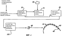
ФИГ.2: Блок-схема процесса изготовления ортодонтических аппаратов согласно реализации настоящего изобретения.FIG. 2: A flowchart of a manufacturing process of orthodontic appliances according to an embodiment of the present invention.
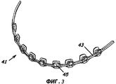
ФИГ.3: Перспективный вид ортодонтического аппарата согласно реализации настоящего изобретения.FIG. 3: A perspective view of an orthodontic apparatus according to an embodiment of the present invention.
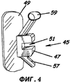
ФИГ.4: Перспективный вид брекета ортодонтического аппарата согласно реализации настоящего изобретения.FIG. 4: A perspective view of a bracket of an orthodontic apparatus according to an embodiment of the present invention.
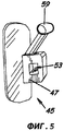
ФИГ.5: Перспективный вид брекета ортодонтического аппарата согласно реализации настоящего изобретения.FIG.5: A perspective view of the bracket of the orthodontic apparatus according to the implementation of the present invention.
ФИГ.6: Перспективный вид паза брекета ортодонтического аппарата согласно реализации настоящего изобретения.FIG.6: A perspective view of the bracket groove of the orthodontic apparatus according to the implementation of the present invention.
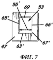
ФИГ.7: Перспективный вид паза брекета ортодонтического аппарата согласно реализации настоящего изобретения.FIG.7: A perspective view of a bracket groove of an orthodontic apparatus according to an embodiment of the present invention.
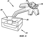
ФИГ.8: Перспективный вид формовочного аппарата согласно реализации настоящего изобретения.FIG. 8: A perspective view of a molding apparatus according to an embodiment of the present invention.
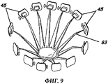
ФИГ.9: Перспективный вид литьевого дерева согласно реализации настоящего изобретения.FIG.9: A perspective view of a cast tree according to the implementation of the present invention.
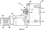
ФИГ.10: Перспективный вид электроискрового аппарата согласно реализации настоящего изобретения.10: A perspective view of an electric spark apparatus according to an embodiment of the present invention.
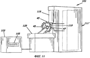
ФИГ.11: Перспективный вид электроискрового аппарата согласно реализации настоящего изобретения.11: A perspective view of an electric spark apparatus according to an embodiment of the present invention.
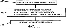
ФИГ.12: Блок-схема способа изготовления ортодонтического аппарата согласно реализации настоящего изобретения.12: A flowchart of a method for manufacturing an orthodontic apparatus according to an embodiment of the present invention.
ФИГ.13: Блок-схема способа изготовления ортодонтического аппарата согласно реализации настоящего изобретения.13: A flowchart of a method for manufacturing an orthodontic apparatus according to an embodiment of the present invention.
ФИГ.14: Перспективный вид брекета ортодонтического аппарата согласно реализации настоящего изобретения.FIG. 14: A perspective view of a bracket of an orthodontic apparatus according to an embodiment of the present invention.
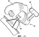
ФИГ.15-19: Перспективный вид части формовочного аппарата и отформованного брекета ортодонтического аппарата согласно реализации настоящего изобретения.15-19: A perspective view of a portion of a molding apparatus and a molded bracket of an orthodontic apparatus according to an embodiment of the present invention.
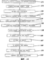
ФИГ.20: Блок-схема способа изготовления ортодонтического аппарата согласно реализации настоящего изобретения.20: A flowchart of a method for manufacturing an orthodontic apparatus according to an embodiment of the present invention.
ФИГ.21: Перспективный вид брекета ортодонтического аппарата с наложенной схемой резки паза согласно реализации настоящего изобретения.21: A perspective view of a bracket of an orthodontic apparatus with a superimposed groove cutting circuit according to an embodiment of the present invention.
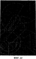
ФИГ.22: Схематический вид брекета ортодонтического аппарата с наложенной схемой резки паза согласно реализации настоящего изобретения.FIG. 22: Schematic view of a bracket of an orthodontic apparatus with a superimposed groove cutting circuit according to an embodiment of the present invention.
ФИГ.23: Последовательность кодов ASCI - команды на выполнение электроискровой резки паза, показанного на ФИГ.22, согласно реализации настоящего изобретения.FIG. 23: ASCI code sequence — instructions for performing spark cutting of a slot shown in FIG. 22, according to an embodiment of the present invention.
ФИГ.24: Блок-схема способа изготовления ортодонтического аппарата согласно реализации настоящего изобретения.24: A flow chart of a method for manufacturing an orthodontic apparatus according to an embodiment of the present invention.
ФИГ.25: Перспективный вид брекета ортодонтического аппарата с наложенной схемой резки паза согласно реализации настоящего изобретения.FIG. 25: A perspective view of a bracket of an orthodontic apparatus with a superimposed groove cutting circuit according to an embodiment of the present invention.
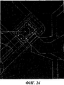
ФИГ.26: Схематический вид брекета ортодонтического аппарата с наложенной схемой резки паза согласно реализации настоящего изобретения.FIG. 26: Schematic view of a bracket of an orthodontic apparatus with a superimposed groove cutting circuit according to an embodiment of the present invention.
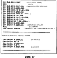
ФИГ.27: Последовательность кодов ASCII - команды на выполнение электроискровой резки паза, показанного на ФИГ.26, согласно реализации настоящего изобретения.FIG. 27: ASCII code sequence — instructions for performing spark cutting of a groove shown in FIG. 26, according to an embodiment of the present invention.
Настоящее изобретение будет описано более полно со ссылками на приложенные чертежи, иллюстрирующие реализации изобретения. Настоящее изобретение может иметь множество реализации, и его не следует считать сводящимся только к реализациям, содержащимся в настоящем описании. Цифрами обозначены соответствующие элементы. Одной и той же цифрой обозначается аналогичный элемент в различных реализациях.The present invention will be described more fully with reference to the accompanying drawings, illustrating implementations of the invention. The present invention may have many implementations, and should not be construed as being limited to the implementations contained in the present description. Numbers denote the corresponding elements. The same number denotes a similar element in various implementations.
Как показано на ФИГ.1-27, реализации настоящего изобретения успешно представляют новую систему, программный продукт, и способы для изготовления элементов ортодонтического аппарата или его частей с использованием электроискровой обработки материалов, и при осуществлении реализации, «резку» различных элементов ортодонтического аппарата, или придания им формы при помощи технологии обработки материала перемещающимся проволочным электродом. Понятие «CAD» включает, без ограничения, любую и все технологии автоматизированного проектирования. Понятие «САМ» включает, без ограничения, любую и все технологии автоматизированного изготовления. Понятие «CNC», или «машинное управление» включает, без ограничения, любую и все технологии цифрового компьютерного управления, относящиеся к производственному оборудованию и системам, включая, без ограничения, системы и устройства быстрого изготовления прототипов. Понятие «резка» включает осуществление электрической эрозии. Понятие «EDM», или «EDM-обработка», включает, без ограничения, любую и все технологии электроискровой обработки. Понятие «3D» обозначает трехмерные объекты. Слова, которые используются в настоящей спецификации для описания настоящего изобретения и различных его реализаций следует понимать не только по их основным значениям, но с включением специальных определений в структуре, материале и актах настоящей спецификации за пределами обычных значений этих слов.As shown in FIGS. 1-27, implementations of the present invention successfully present a new system, software product, and methods for manufacturing elements of an orthodontic apparatus or parts thereof using electric spark processing of materials, and when implementing, “cutting” various elements of an orthodontic apparatus, or shaping them using technology to process the material with a moving wire electrode. The term CAD includes, without limitation, any and all computer aided design technologies. The term "CAM" includes, without limitation, any and all automated manufacturing technologies. The concept of "CNC", or "machine control" includes, without limitation, any and all digital computer control technologies related to manufacturing equipment and systems, including, without limitation, systems and devices for rapid prototyping. The term “cutting” includes the implementation of electrical erosion. The term "EDM", or "EDM processing", includes, without limitation, any and all technologies of electric spark processing. The term “3D” refers to three-dimensional objects. Words that are used in this specification to describe the present invention and its various implementations should be understood not only by their basic meanings, but with the inclusion of special definitions in the structure, material and acts of this specification beyond the usual meanings of these words.
Как показано на ФИГ.1 и 2, реализация системы 30, предназначенной для фабрикации или изготовления ортодонтических аппаратов, может включать компьютер 31 для виртуального проектирования ортодонтических аппаратов, имеющий процессор 33, и память 35, подключенную к процессору 33, и программный продукт 37 для виртуального проектирования ортодонтических аппаратов, хранящийся в памяти 35. Программа 37 для виртуального проектирования ортодонтических аппаратов может включать инструкции на выполнение операций по получению данных о зубном аппарате пациента, полученные различными способами, известными специалистам в данной области, и может включать инструкции на выполнение операций по созданию виртуального пространственного представления ортодонтического аппарата 41, определяющего данные виртуального проектирования ортодонтического аппарата в ответ на полученные данные о зубном аппарате пациента.As shown in FIGS. 1 and 2, an implementation of a
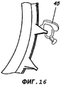
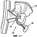
Как показано на ФИГ.4-7, ортодонтический аппарат 41 может включать индивидуально изготовленную проволочную дугу 43 и множество прецизионных индивидуально изготовленных брекетов 45, каждый из которых включает тело брекета 47, подложку брекета 49, соединенную с телом брекета 47, и паз брекета 51, 53, в теле брекета 47, с шириной паза брекета 55. Тело брекета 47 может также включать крыло брекета 57, крючок брекета 59 и прочие конструктивные элементы, известные специалистам в данной области. Открытый паз брекета 51 может включать конец открытой поверхности 61, конец закрытого основания 63 и две стороны 65 и 66, находящиеся между концами. Паз с открытым концом 51 (см. ФИГ.4 и 6) может также включать поперечный участок или участки, примыкающие к концу основания 63, и продолжающийся в тело брекета 47 от одной или обеих сторон 65 и 66, образуя подрез 67, имеющий ширину, превосходящую ширину паза 55. Часть тела брекета 47, примыкающая к открытому концу 61, может быть дугообразной или иметь более планарную форму. Стороны 65 и 66 и основание 63 паза брекета 51 могут иметь в целом планарную поверхность и, соответственно, могут быть определены как имеющие пространственный допуск менее 30 микрон и, предпочтительно, вплоть до 8 микрон, например вдоль ширины паза 55. Паз с закрытым концом 53 (см. ФИГ.5 и 7) может включать поверхность закрытого конца 69, но в остальном он подобен пазу с открытым концом 51. То есть паз с закрытым концом 53 также включает основу 63', две стороны 65' и 66', ширину 55' и может включать подрезку 67'. Аналогично трубообразный паз 53 можно определить как имеющий допуск менее 30 микрон и, предпочтительно, вплоть до 8 микрон вдоль ширины паза 55'.As shown in FIGS. 4-7, the
Как показано на ФИГ.8, система 30 может также включать формовочный аппарат 71, известный специалистам в этой области, который может применять различные технологии, такие как, например, быстрое изготовление прототипов для образования формы 73, применяющейся для формовки индивидуально изготовленных брекетов 45. Различные технологии быстрого изготовления прототипов, например, могут включать стереолитографию, изготовление ламинированных объектов, селективное лазерное спекание, моделирование наплавкой, выдержку твердеющего материала, трехмерную струйную печать и т.д. и т.п. Согласно реализации настоящего изобретения форма 73 конфигурируется таким образом, чтобы одновременно образовать тело брекета 47 и подложку брекета 49. Форма 73 устанавливается так, чтобы принять материал 75, из которого изготавливается брекет, а устройство распределения материала 77 служит для подачи материала 75, из которого изготавливается брекет, в форму 73. В реализации настоящего изобретения, как это, возможно, наилучшим образом описано в патенте США №6776614, принадлежащем Вичмену и др. (Wiechman et al.) и озаглавленном «Модульная система для индивидуальных ортодонтических аппаратов», включенном в настоящую заявку путем сноски на ее полноту, применяется компьютерное проектирование брекета 45, включая тело брекета 47 и подложку брекета 49, осуществляется по данным трехмерного сканирования оттиска зубов пациента, а технология быстрого изготовления прототипов применяется для изготовления моделей брекета 45 из парафина или смолы, каковые модели затем используются для изготовления форм 73 из, например, цемента, для изготовления брекетов 45. Каждая форма 73 обычно имеет полость 79 для каждого из брекетов 45 и для определения контуров тела брекета 47 и подложки брекета 49, когда материал для изготовления брекета 75 помещается в форму, и канал 81, определяющий контуры литника 83 (ФИГ.9) при наполнении формы материалом 75. Как, возможно, это лучше показано на ФИГ.14, каждое отформованное тело брекета 47 может быть соединено с литником 83 после извлечения из формы 73.As shown in FIG. 8,
Как показано на ФИГ.1 и 2, система 30 может также включать компьютер для обработки данных 91, соединенный, например, с компьютером 31, предназначенным для проектирования ортодонтического аппарата, через компьютерную сеть 93 и имеющий память 95 и программу компьютеризированного проектирования 97, хранящуюся в памяти 95. Программа компьютеризированного проектирования 97 может включать инструкции на выполнение операций по формированию команд управления устройством электроискровой обработки, читаемые этой машиной для выполнения операций по формированию паза брекета 51 и 53. Эти инструкции могут также включать инструкции на выполнение операций по одновременному отделению тела брекета 47 от секции крепления литника 83 при формировании паза брекета 51 и 53. Следует отметить, что, согласно реализации предыдущего изобретения, данные виртуального проектирования ортодонтического аппарата могут вводиться вручную в компьютер 91, предназначенный для обработки данных, или быть иным образом получены этим компьютером. Такой способ можно применять, когда конструктивный элемент, например ширина паза брекета 55 или 55', описывается ограниченным числом параметров. Если же конструктивный элемент является более сложным, то тогда более предпочтителен ввод данных виртуального проектирования с компьютера 31, предназначенного для проектирования. Следует отметить, что память 95, вместе с другим описанным устройством памяти, может включать энергозависимое и энергонезависимое устройство памяти, известно специалистам в данной области, включая, например, приводы RAM, ROM, магнитные или оптические диски и т.д. и т.п. Также следует отметить, что инструкции по управлению устройством электроискровой обработки, выпускаемые программой компьютеризованного изготовления, могут выдаваться в виде микрокодов, программ, процедур и текстов на алгоритмическом языке, образуя набор и наборы заказанных операций, управляющих и направляющих функционирование аппаратных систем. Согласно реализации настоящего изобретения эти инструкции специально рассчитаны на использование цифровым устройством управления.As shown in FIGS. 1 and 2, the
Как показано на ФИГ.1 и 2, система 30 также включает аппарат электроискровой обработки 101, соединенный с компьютером для обработки данных 91 через, например, компьютерную сеть 93, используя, например, последовательный порт связи RS-232-C или другие средства коммуникации, известные специалистам в этой области. Аппарат 101 для электроискровой обработки материала может включать контроллер 103, например блок управления машиной, имеющий память 105, каковой блок может обеспечивать цифровое управление машиной с компьютера. Контроллер 103 может также включать устройство или устройства пользовательского ввода, известные специалистам в этой области, и программу обмена данными 107, хранящуюся в памяти 105, каковая программа может включать инструкции на получение или импортирование формирования управляющего сигнала для устройства электроискровой обработки. Контроллер 103 может также включать управляющую программу 109, включающую инструкции на формирование управляющего сигнала, содержащего команды для устройства электроискровой обработки, в ответ на полученные управляющие инструкции электроискрового устройства. Следует отметить, что, согласно реализации настоящего изобретения, контроллер 103 может попеременно получать управляющие инструкции электроискрового устройства от компьютера обработки данных 91 через среду ручной передачи данных, например, при помощи носителя, читаемого на портативном компьютере.As shown in FIGS. 1 and 2, the
Как показано на ФИГ.10 и 11, аппарат для электроискровой обработки материалов 101 может также включать электроискровое устройство 111, 111', имеющее узел разрядных электродов 113, 115, включающий электрод 117, 119. Обычно источник напряжения постоянного тока и искровой контроллер, находящийся в электрическом подключении к источнику постоянного тока (не показан), обеспечивает создание высокочастотной пульсирующей волны, которая образует соответствующие высокочастотные серии электродуговых разрядов между электродами 117, 119 и частью тела брекета 47, примыкающей к электроду 117, 119. Электроды электроискрового устройства 111, 111', например, могут быть двух типов, а именно подвижный проволочный электроразрядный электрод или подвижный проволочный электрод 117 (ФИГ.10) или разрядный электрод объемного фрезерования 119 (ФИГ.11).As shown in FIGS. 10 and 11, the apparatus for electric spark processing of
Как показано на ФИГ.10, электродный узел 113 электроискрового устройства 111. использующий перемещающийся проволочный электрод 117, включает подающую катушку или шпульку 121, содержащую неиспользованную часть перемещающегося проволочного электрода 117 для обеспечения постоянного потока подачи перемещающегося проволочного электрода при выполнении схемы резки, и приемную катушку или шпульку 123, содержащую использованную часть перемещающегося проволочного электрода, на каковую приемную катушку 123 наматывается электрод, сматывающийся с катушки подачи 121 во время выполнения схемы резки при формировании паза брекета 51 и для обеспечения должного натяжения проволочного электрода 117. Между катушкой подачи 121 и приемной катушкой 123 находятся подающая 125 и приемная 127 направляющие проволоки. Проволочный электрод 117, постоянно подаваемый с катушки подачи 123 во время выполнения операций резки, удерживается между подающими и приемными направляющими 125, 127. Перемещающийся проволочный электрод 117 обычно использует воду в качестве своего диэлектрика, причем вода может подаваться через сопла (не показаны), находящиеся вплотную к телу брекета 47. Для увеличения скорости обработки можно выбрать отрицательную полярность электрода. Положительную полярность электрода можно выбрать для создания более ровной поверхности паза в брекете. Можно также использовать комбинацию двух полярностей, в зависимости от необходимости.As shown in FIG. 10, the
Согласно реализации настоящего изобретения электроискровое устройство 111 включает приводной стол 129 аппарата электроискровой обработки, как это будет понято специалистами в данной области, каковой стол приспособлен для перемещений в плоскости Х-У, например, используя устройство пошагового перемещения или электромоторы постоянного тока (не показаны), действующие в ответ на управляющий сигнал, предписывающий привести тело брекета 47 в электрический разрядный контакт с перемещающимся проволочным электродом 117, чтобы таким образом выполнить схему резки для создания паза 51, 53. Согласно другой реализации настоящего изобретения подающая и приемная направляющие 125, 127 перемещаются в ответ на управляющий сигнал в плоскости Х-У, например, используя устройство пошагового перемещения или электромоторы постоянного тока (не показаны), как это будет понято специалистами в данной области, для приведения перемещающегося проволочного электрода 117 в положение, необходимое для осуществления схемы резки. Согласно реализации настоящего изобретения направляющая подачи 125 и принимающая направляющая 127 могут, кроме того, быть расположены независимо, что позволит создавать различные геометрические формы с непараллельными и непланарными поверхностями. Следует отметить, что перемещающийся проволочный электрод 117 при помощи одной или обеих направляющих 125, 127 или при помощи приводного стола 129 может также одновременно отделить тело брекета 47 от литника 83 в ответ на управляющий сигнал.According to an embodiment of the present invention, the
Как показано на ФИГ.11, электродный узел 115 электроискрового устройства 111', использующего электроискровой электрод объемного фрезерования 119, может включать поршень (не показан) для протягивания электрода, примыкающего к телу брекета 45 при создании отверстия, образующего часть паза брекета 53. Следует отметить, что вместо специального электрода объемного фрезерования 119 можно применить часть перемещающегося проволочного электрода 117, отсоединенного от приемной катушки 125, благодаря чему он будет действовать как электрод объемного фрезерования. Следует отметить, что согласно реализациям настоящего изобретения другие способы изготовления, включающие, например, сверление стартерного отверстия сквозь тело брекета 47 или создание стартерного отверстия в теле брекета 47 как часть процесса его формовки, также относятся к составу настоящего изобретения. Независимо от способа, используемого для создания первоначального отверстия, после формирования первоначального отверстия в теле брекета 47 конец перемещающегося проволочного электрода 117 может быть подсоединен к приемной катушке 125 для функционирования, как это описано выше, для создания паза брекета 53 в форме трубки, как это описано ниже.As shown in FIG. 11, the
Как показано на ФИГ.1-27, реализации настоящего изобретения также включают способы изготовления ортодонтических аппаратов. Например, как показано на ФИГ. 12, согласно реализации настоящего изобретения способ изготовления ортодонтических аппаратов может включать получение данных о зубном аппарате пациента (блок 141), которые могут быть получены, например, путем обследования/диагностики аномалии прикуса при помощи процедур, известных специалистам в этой области, проектирование виртуального пространственного представления ортодонтического аппарата по данным о зубном аппарате пациента (блок 143) и затем изготовление ортодонтического аппарата (блок 145). Например, ортодонт или другой медицинский работник проводит обследование пациента в кабинете ортодонта для сбора данных, необходимых для определения состояния пациента, предписывает надлежащее лечение и определяет характеристики ортодонтического аппарата, который будет применяться для этого лечения. Физическая модель, включающая мандибулярную и максиллярную модели нижней и верхней челюсти пациента соответственно, могут быть сформированы при помощи физической формы, которая будет использоваться для построения виртуальной модели. Независимо от применяемого способа виртуальная модель вместе с предписанием в отношении лечения пациента, а также результат, который должен быть достигнут лечением, могут быть использованы для формирования данных по зубному аппарату пациента. Эти данные могут быть переданы на устройство проектирования и изготовления ортодонтического аппарата, где проектирование индивидуально изготовленного ортодонтического аппарата 41 может быть выполнено при помощи компьютера, например компьютера 31 для виртуального проектирования ортодонтических аппаратов, или при помощи рабочей станции, или при помощи иного процессора данных, известного специалистам в этой области, каковой процессор способен хранить трехмерную виртуальную модель зубного аппарата пациента и программное обеспечение планирования лечения или программный продукт для перемещения зубов в виртуальной модели для принятия решения об их окончательном положении.As shown in FIGS. 1-27, implementations of the present invention also include methods for manufacturing orthodontic appliances. For example, as shown in FIG. 12, according to an embodiment of the present invention, a method for manufacturing orthodontic appliances may include obtaining data on a patient’s dental apparatus (block 141), which can be obtained, for example, by examining / diagnosing malocclusion using procedures known to those skilled in the art, designing a virtual spatial representation orthodontic apparatus according to the patient’s dental apparatus (block 143) and then manufacturing the orthodontic apparatus (block 145). For example, an orthodontist or other medical professional examines a patient in the orthodontist’s office to collect the data necessary to determine the patient’s condition, prescribes appropriate treatment and determines the characteristics of the orthodontic appliance that will be used for this treatment. The physical model, including the mandibular and maxillary models of the lower and upper jaw of the patient, respectively, can be formed using the physical form that will be used to build the virtual model. Regardless of the method used, the virtual model along with the prescription regarding the treatment of the patient, as well as the result that must be achieved by the treatment, can be used to generate data on the patient’s dental apparatus. This data can be transferred to a device for designing and manufacturing an orthodontic apparatus, where the design of an individually manufactured
Ортодонтический аппарат 41 может включать индивидуально изготовленную проволочную дугу 43 и набор прецизионных индивидуально изготовленных брекетов 45, каждый из которых включает тело брекета 47, подложку брекета 49, соединенную с телом брекета 47, и паз брекета 51, 53 в теле брекета 47. Различные системы и способы формирования проволочной дуги, описанные, например, в патенте США №6928733, принадлежащем Рубберту и др. (Rubbert et al.) и озаглавленном "Способ и система для индивидуальной подгонки ортодонтической проволочной дуги», включенном в настоящее описание путем ссылки на его целостность, могут использоваться для формирования прецизионной проволочной дуги 43, которая будет вставляться в пазы брекета 51, 53, для формирования прецизионного интерфейса, которое может быть реализовано в ширине паза брекета при, например, комбинированном допуске, равном или меньшем двадцати микрон или вплоть до восьми микрон. Проволочная дуга 43 обычно изготавливается из нержавеющей стали, или на основе никель-титановых, титан-ниобиевых или титан-молибденовых сплавов, но может также быть изготовлена из различных иных материалов, известных специалистам в этой области. Брекеты 45 обычно изготавливаются из нержавеющих сталей, или титана, или титановых сплавов, однако готовые брекеты могут изготовляться из различных иных материалов, известных специалистам в этой области.The
Могут быть применены различные способы формирования виртуальной подложки брекета и тела брекета. Патент США №6776614, принадлежащий Вичмену и др. (Wiechmann et al.), озаглавленный «Модульная система для индивидуальных ортодонтических аппаратов», включенный в настоящее описание путем ссылки на его целостность, описывает способы проектирования виртуального пространственного представления ортодонтического аппарата 41, применяемые для изготовления брекетов 45, включая системы и способы проектирования индивидуально изготовленного ортодонтического брекета при помощи компьютера, имеющего доступ к библиотеке виртуальных описаний элементов брекетов. Например, согласно одному из этих способов геометрия подложки брекета может быть получена непосредственно из цифровых представлений зубов пациента, с тем чтобы изготовить клеящуюся подложку брекета 49, которая бы существенно отвечала форме поверхности зуба. Согласно другому способу, описанному Вичменом и др. (Wiechmann et al.), применяется программный алгоритм, который автоматически или полуавтоматически рассчитывает зону примыкания подложки брекета путем анализа кривизны поверхности зуба и определяет поверхность, которая достаточно велика для того, чтобы покрыть существенные элементы кривизны, что позволяет вручную осуществить надежное позиционирование брекета 45 на поверхности зуба. Такой алгоритм может, например, начинать работу с предварительно заданной величины подложки. Поверхность зуба, покрытая подложкой этой величины, образует виртуальный «бугор», имеющий по крайней мере одну приподнятую часть по отношению к остальной анатомии зуба, поскольку для установки брекета на зубе невозможно найти абсолютно плоскую поверхность. Объем этого выступа можно рассчитать при том условии, что края подложки соединены непрерывной поверхностью любым удобным образом. Чем меньше кривизна поверхности зуба, тем этот выступ более плоский и тем меньше его объем. Если объем этого «бугра» не превосходит заранее заданной величины, то подложка автоматически будет увеличена на заранее заданную величину, с той целью, что больший объем с большей вероятностью будет включать адекватные приподнятые элементы зуба. Затем объем рассчитывается снова. Такие циклы повторяются до тех пор, пока не будет достигнута минимальная величина объема для каждой подложки. Это только пример подхода к такому автоматизированному алгоритму. На основе принципов, содержащихся в этом подходе, можно выбрать большое количество других готовых алгоритмов.Various methods of forming a virtual bracket substrate and a bracket body can be applied. US patent No. 6776614, owned by Wichman et al. (Wiechmann et al.), Entitled "Modular system for individual orthodontic appliances", incorporated into this description by reference to its integrity, describes methods for designing a virtual spatial representation of an
Часть подложки брекета 49, не примыкающая непосредственно к зубу пациента, также можно спроектировать таким образом, чтобы она отвечала геометрии зуба пациента. Кроме того, также можно спроектировать брекетные тела 47 и скомбинировать их с брекетными подложками 49. Например, библиотека брекетных тел 47 создается заранее и хранится в компьютере, что позволяет выбирать из готовых вариантов, причем готовые брекетные тела 47 можно адаптировать к индивидуальному пациенту. Например, пазы брекета 51, 53 также можно спроектировать в соответствии с геометрией зубов пациента, пазы брекета 51, 53 могут быть как пазами с открытым концом 51, распространяющимися внутрь поверхности тела брекета, так и пазами с закрытым концом 53, образующими трубку, проходящую через тело брекета 47. Данный способ изготовления имеет то преимущество, что допуск вдоль ширины паза брекета 55 любого типа паза брекета 51 или 53, например, может быть меньше тридцати микрон и вплоть до восьми микрон, что соответствует расчетному углу поворота только лишь 0,7 градуса. Это обстоятельство может быть существенным улучшением предыдущего состояния данной техники, которая имеет более грубые допуски - около 40 микрон для пазов с открытым концом и от 40 до 100 микрон для пазов с закрытым концом. Такая точность обработки поверхности может в итоге привести к более предсказуемым конечным результатам лечения.A portion of the
Кроме того, прочие принадлежности, такие как крыло брекета 57 или крючок брекета 59, могут быть интегрированы в проект брекета. После того как трехмерные проекты подложки брекета 49, тела брекета 45 и прочих принадлежностей скомбинированы, процесс повторяется для каждого брекета 45, образующего ортодонтический аппарат.In addition, other accessories, such as
Как показано на ФИГ. 13, согласно реализации настоящего изобретения способ изготовления ортодонтического аппарата может включать различные технологии формовки, которые известны и понятны специалистам в этой области. То есть этот способ может включать литье, впрыскивание или иную подачу материала для изготовления брекета 75 в форму 73 (блок 151). Форма 73 (ФИГ. 8) может иметь полость 79 для каждого из брекетов 45, определяющую контур тела брекета 47 и подложки брекета 49, когда материал для изготовления брекета 75 помещается в нее. В форме 73 с каждой полостью 79 связан отдельный канал или литниковый ход 81, являющийся отдельным проводником для материала изготовления брекета 75, поступающего в полость 79. Каждый канал 81 определяет контур литника 83, заполненного материалом для изготовления брекета 75. Согласно реализации настоящего изобретения после затвердевания материала изготовления брекета 75 и после удаления брекетов 45 из формы 73 каждое отлитое тело брекета 47 остается связанным с литником 83 (см. ФИГ.9 и 14-19). Если литники 83 соединены вместе, то обычно говорят, что они образуют «литьевое дерево».As shown in FIG. 13, according to an embodiment of the present invention, a method for manufacturing an orthodontic apparatus may include various molding techniques that are known and understood by those skilled in the art. That is, this method may include casting, injecting, or otherwise feeding material to make the
Согласно реализации настоящего изобретения способ изготовления ортодонтического аппарата может включать применение технологий автоматизированной обработки материалов. То есть способ изготовления ортодонтического аппарата 41 может включать формирование управляющих инструкций для исполнительного устройства, например, используя компьютер для обработки данных, например компьютер для обработки данных 91, включая программное обеспечение, например программу для компьютеризированного изготовления 97 (ФИГ.1), которая описана выше и которая может использоваться для формулирования управляющих инструкций для исполнительного устройства от виртуального пространственного представления паза брекета 51, 53 в теле брекета 47 (блок 153). Инструкции для управления устройством описывают операции по выполнению схемы резки вдоль контура паза брекета 51, 53, каковая схема может задаваться индивидуально для обеспечения существенного совпадения с соответствующими размерами предварительно выбранной индивидуально изготовленной прецизионной проволочной дуги 43, для формирования, таким образом, прецизионного интерфейса с проволочной дугой 43. Управляющие инструкции для устройства могут подаваться как вручную, так и передаваться через компьютерную сеть на контроллер, например контроллер 103, устройства изготовления брекетов, например электроискрового устройства 111, 111' (блок 155). Управляющий сигнал, несущий управляющие инструкции для электроискрового устройства, формируется затем (блок 157) в ответ на полученные управляющие команды электроискрового устройства, например контроллером 103, содержащим управляющую программу 109. Схема электроискровой резки затем осуществляется в ответ на управляющие сигналы, и, таким образом, изготавливается паз брекета 51, 53 (блок 159).According to an embodiment of the present invention, a method for manufacturing an orthodontic apparatus may include the use of automated material processing technologies. That is, the manufacturing method of the
Как показано на ФИГ.20, согласно реализации настоящего изобретения, если паз брекета является пазом с открытым концом 51, способ изготовления ортодонтического аппарата 42 может включать выполнение схемы электроискровой резки электрической в ответ на управляющий сигнал на формирование паза брекета, как это показано на ФИГ.21 и 22. При конфигурации паза брекета с открытым концом паз брекета 51 имеет открытый конец 61, закрытый конец основания 63 и две противоположные стороны 65, 66, протянувшиеся между концом основания 63 и открытым концом 61, и, например, такой паз может быть прорезан параллельно внутренней поверхности зуба, с тем чтобы брекет был установлен на подложке брекета и/или выровнен в соответствии с общей ориентировкой подложки брекета 49. То есть паз брекета 51 может быть ориентирован существенно параллельно ориентировке поверхности зуба, или геометрии подложки брекета, или им обоим. Аналогично, согласно реализации настоящего изобретения, тело брекета 47 может иметь форму, существенно совпадающую с формой соответствующего зуба.As shown in FIG. 20, according to an embodiment of the present invention, if the bracket groove is an
Согласно реализации настоящего изобретения паз 51 «врезается» в тело брекета 47 при помощи электроискрового аппарата 101, включающего электроискровое устройство 111, оснащенное перемещающимся проволочным электродом 117 (см. ФИГ.10). Контроллер 103 электроискрового аппарата получает инструкции на управление устройством либо непосредственно от пользователя, либо через коммуникационную линию, подсоединенную к компьютеру обработки данных 91 или к системе, выдающей инструкции управления устройством, описывающие движения электрода 117 или брекетов 45 для формирования схемы электроискровой резки (блок 171). Например, компьютер обработки данных 91 может иметь программу компьютеризированного изготовления или код 97, которые могут получать входную информацию либо от компьютера 31 виртуального проектирования ортодонтического аппарата, включающего программу ортодонтического проектирования, либо от иного типа программы компьютеризированного проектирования, находящейся вместе с программой компьютеризированного изготовления в самом компьютере обработки данных 91. Согласно реализации настоящего изобретения программа компьютеризированного изготовления 97 может использоваться для формирования инструкций управления устройством, например программа уровня G-кода, такая как показано на ФИГ.23 (блок 173), как это могут понять специалисты в данной области. Как сказано выше, этот код может легко передаваться в контроллер 103 электроискрового аппарата для осуществления управления осуществлением схемы электроискровой резки (блок 175).According to the implementation of the present invention, the
После отливки брекеты 45 могут находиться в виде «литьевого дерева», будучи соединены литниками 83. После извлечения брекетов 45 из формы 73 каждый из брекетов 45 с соответствующим литником 83 помещаются на приводной стол электроискрового аппарата для прорезки паза в теле каждого брекета и для отделения брекета от литьевого дерева. После помещения литьевого дерева поблизости от электрода 117 (блок 177) может быть инициировано выполнение схемы электроискровой резки (блок 179). Выполнение схемы электроискровой резки может быть инициировано как вручную оператором электроискрового аппарата, так и автоматически при помощи датчиков, известных специалистам в данной области. Согласно реализации настоящего изобретения приводной стол 129 электроискрового аппарата, несущий литьевое дерево, может по отдельности помещать каждое тело брекета 47 в положение электроискрового контакта с перемещающимся проволочным электродом 117. Согласно другой реализации настоящего изобретения это осуществляется путем движения соответствующих направляющих 125, 127.After casting, braces 45 can be in the form of a “cast wood”, being connected by
После инициирования выполнения схемы электроискровой резки первый брекет 45 на литьевом дереве приводится в такое положение, чтобы первый брекет 45 пришел в надлежащее соприкосновение с перемещающимся проволочным электродом 117 в начальной точке, например - в начальной точке Р1, показанной на ФИГ.21 (блок 181), которая относится к нулевой точке программы аппарата 101, как это известно специалистам в данной области. Кроме того, подающая катушка 121, содержащая неиспользованные участки перемещающегося проволочного электрода 117, начинает непрерывную подачу перемещающегося проволочного электрода 117, а приемная катушка 123, содержащая использованные части перемещающегося проволочного электрода, начинает вбирать перемещающийся проволочный электрод 117, поступающий с катушки подачи 121. Через перемещающийся проволочный электрод 117 пропускают высокочастотный электрический ток, а диэлектрическая жидкость (не показана) подается таким образом, чтобы напряжение в зазоре между перемещающимся проволочным электродом 117 и телом брекета 47 ионизировало диэлектрическую жидкость, что позволит «искре» осуществлять процесс эрозии на теле брекета 47 для образования паза брекета 51.After initiating the execution of the spark cutting circuit, the
Согласно реализации настоящего изобретения в ответ на инструкции управления приводом приводной стол 129 и, соответственно, тело брекета 47 приводятся в положение для перемещения брекета 45 согласно первому участку L1 схемы резки, так чтобы перемещающийся проволочный электрод 1177 пришел в положение электрического контакта, но непосредственно не касался тела брекета 47. В точке Р1 электрод 117 приходит в электрический контакт с телом брекета 47, и начинается процесс эрозии (блок 183), плавления или испарения части поверхности брекета 45. Тело брекета 47 после этого перемещается по траектории L2 до достижения желаемой начальной точки Р2 первой стороны 65 паза брекета 51. Фактически эта начальная часть схемы резки, в особенности вторая ветвь L2, может продолжать схему резки вдоль части внешней поверхности тела брекета 47 существенно поперек первой стороне 65 и внутрь части литника 83.According to an embodiment of the present invention, in response to the drive control instructions, the drive table 129 and, accordingly, the
Тело брекета затем перемещается вдоль ветви L3 до достижения желаемой глубины внутри тела брекета 47, образуя длину первой стороны 65 (блок 185). Затем тело брекета 47 перемещается вдоль траектории L4 до достижения желаемой поперечной глубины в теле брекета 47, образуя поперечное протяжение в тело брекета от первой стороны. Затем тело брекета 47 перемещается обратно по траектории L4, а затем перемещается вдоль траектории L5 до достижения желаемой поперечной глубины в теле брекета 47, образуя основание паза брекета 63 и образуя поперечное протяжение в тело брекета от второй стороны 66 (блок 187). После этого тело брекета перемещается обратно по траектории L5 до достижения желательной начальной точки Р3 внутри тела брекета для того, чтобы начать формирование второй стороны 66. Поперечные протяжения, выходящие за первую и вторую стороны 65, 66, образуют подрезку 67 паза брекета (блок 189). Тело брекета 47 после этого перемещается вдоль траектории L6 до достижения конечной точки Р4 схемы резки брекетного паза, каковая точка обычно находится рядом с начальной точкой Р1 первой стороны 65, образуя длину второй стороны 66 (блок 191). Следует отметить, что первая и вторая стороны 65, 66, хотя они и показаны как параллельные, могут образовывать острый угол с основанием 63 брекетного паза 51, так что две разнесенные стороны 65, 66 сходятся в направлении от основания 63 брекетного паза к отверстию брекетного паза 61, или наоборот, в направлении от отверстия брекетного паза 61 к основанию 63 брекетного паза.The bracket body then moves along the branch L3 to achieve the desired depth inside the
Тело брекета 47 затем перемещается вдоль траектории L7 до начала литника 83, эффективно отделяя тело брекета 47 от литника 83 и, тем самым, от литьевого дерева (блок 193). Если конструкция тела брекета включает крыло брекета 57, такое как показано на ФИГ. 4 и 21, то тело брекета 47 перемещается дальше таким образом, чтобы схема резки была вдоль поверхности крыла брекета 57 со стороны паза, с тем чтобы образовать поверхности крыла брекета 57 со стороны паза, отделяя тело брекета 47 от литника 83. Следует отметить, что, как это описано выше, вместо перемещения тела брекета 47 предпочтительнее перемещать направляющие 125, 127, для того чтобы выполнить операции, как описанные выше, так и описанные ниже.The body of the
Как показано на ФИГ.24, согласно реализации настоящего изобретения, если паз брекета является пазом с закрытым концом 53, определяющим канал или трубку, проходящую через тело брекета 47, то способ изготовления ортодонтических аппаратов 41 может включать выполнение схемы электроискровой резки в ответ на управляющий сигнал сформировать паз брекета, как показано на ФИГ.25 и 26. При трубочной конфигурации паза брекета паз брекета 53 имеет закрытый периметр и располагается в теле брекета 47. Трубчатый паз брекета 53, подобно пазу брекета с открытым концом 51, может также, например, быть сформирован параллельно внутренней поверхности зуба, с тем чтобы тело брекета 47 располагалось на и/или в общей ориентации подложки брекета 49. То есть паз брекета 53 может быть ориентирован существенно параллельно ориентации поверхности зуба, геометрии подложки или им обеим. Аналогично тело брекета 47, несущее паз брекета 53, имеющий трубчатую форму, может также иметь форму, существенно отвечающую форме соответствующего зуба.As shown in FIG. 24, according to an embodiment of the present invention, if the bracket groove is a groove with a
Согласно реализации настоящего изобретения в ответ на управляющий сигнал выполняется первая схема электроискровой резки, что приводит к формированию брекетной трубки 53. Схема резки вытянута вдоль периметра брекетной трубы 53 и может быть отрегулирована, чтобы обеспечить существенное соответствие размерам заранее выбранной проволочной дуги, чтобы таким образом сформировать прецизионный интерфейс с проволочной дугой 43. Брекетная трубка 53 «вырезается» в теле брекета 47 при помощи, например, комбинации электрода объемного фрезерования 119 и перемещающегося проволочного электрода 117. Контроллер 103 электроискрового аппарата, как это описано выше, может получать инструкции для управления устройством, например такие, как показано на ФИГ.27, как непосредственно от пользователя, так и через коммуникационную линию, ведущую к компьютеру обработки данных 91 или системе, выдающей управляющие инструкции для устройства, описывающие движение электродов при выполнении схемы электроискровой резки (блок 201). Альтернативно начальное отверстие может быть выполнено другими средствами, известными специалистам в этой области. После помещения литьевого дерева (блок 203) может быть инициировано выполнение схемы электроискровой резки (блок 205) как вручную оператором электроискрового аппарата 101, так и автоматически при помощи датчиков, известных специалистам в этой области.According to an embodiment of the present invention, in response to a control signal, a first spark cutting circuit is performed, which results in the formation of the
После инициирования выполнения схемы электроискровой резки первый брекет 45 на литьевом дереве, сквозь который требуется прорезать трубку, помещается так, чтобы брекет был в надлежащем контакте с перемещающимся проволочным электродом 117 в начальной точке, например начальной точке ТР0, показанной на ФИГ. 25, которая может быть соотнесена с нулевой программной точкой электроискрового устройства 111'. Если стартерный канал не был изготовлен заранее (блок 207), то электрод объемного фрезерования 119 или отсоединенная часть перемещающегося проволочного электрода 117 может использоваться для формирования или углубления стартерного канала (блок 209). Через электроды 117, 119 пропускают высокочастотный электрический ток, а диэлектрическая жидкость подается таким образом, чтобы электрическое напряжение в зазоре между электродами 117, 119 и телом брекета 47 могло ионизировать диэлектрическую жидкость, чтобы осуществлять процесс эрозии на теле брекета для образования стартерного канала для брекетной трубки 53. После прорезки канала 130, чтобы создать пространство для нормального развертывания перемещающегося проволочного электрода 117, перемещающийся проволочный электрод 117 пропускается через канал 130 в начальной точке ТР0 (блок 211). Подающая катушка 121, содержащая неиспользованные участки перемещающегося проволочного электрода 117, начинает непрерывную подачу перемещающегося проволочного электрода 117, а приемная катушка 123, содержащая использованные части перемещающегося проволочного электрода, начинает вбирать перемещающийся проволочный электрод 117, поступающий с катушки подачи 121 со скоростью, заданной пользователем или определяющейся характером материала. Как это описано выше, также пропускают высокочастотный ток через перемещающийся проволочный электрод 117, а диэлектрическая жидкость подается для осуществления эрозионного процесса на теле брекета 47 для формирования трубки брекета.After initiating the execution of the spark cutting circuit, the
Согласно предпочтительной реализации настоящего изобретения в ответ на управляющие команды привода тело брекета перемещается вдоль первой траектории TL1 схемы резки и перемещающийся проволочный электрод 117 создает электрическую эрозию материала тела брекета до части желаемого периметра трубки брекета 53 (блок 213), например в начальной точке периметра ТР1. Тело брекета затем перемещается вдоль траектории TL2 до достижения желательной начальной точки ТР2 первой стороны 65'. После этого тело брекета 47 перемещается вдоль траектории TL3 до достижения желаемой длины брекетной трубки 53. Поле этого тело брекета 47 перемещается вдоль траектории TL4 до достижения желаемой ширины 55' паза брекета 53. После этого тело брекета 47 перемещается вдоль траектории TL5 до достижения желаемой длины второй стороны 66'. После этого тело брекета 47 перемещается до достижения стартовой точки ТР1 начального периметра, завершая тем самым периметр паза брекета 53 (блок 215). Перемещающийся проволочный электрод 117 после этого удаляется из трубки брекета 53 (блок 217). Следует отметить, что хотя первая и вторая стороны 65' и 66' показаны параллельными, на самом деле они могут образовывать острый угол с основанием паза брекета 63' в пазе брекета 5, так что две разнесенные стороны 65' и 66' могут сходиться как по направлению от основания паза брекета 63', так и по направлению к основанию паза брекета 63'. Далее, подобно пазу брекета с открытым концом 51, описанному выше, либо длина, либо ширина одной или более траекторий может быть увеличена таким образом, чтобы длина резки превосходила длину или ширину трубки брекета 53, тем самым образуя подрезку.According to a preferred embodiment of the present invention, in response to the drive control commands, the bracket body moves along the first path TL1 of the cutting circuit, and the moving
Согласно реализации настоящего изобретения в ответ на управляющий сигнал может быть выполнена вторая схема электроискровой резки для отделения тела брекета от литника 83 (см. ФИГ.25-27). После инициирования выполнения второй схемы электроискровой резки (блок 221) тело брекета снова устанавливается таким образом, чтобы брекет 45 находился в надлежащем контакте с перемещающимся проволочным электродом 117 (блок 223) в стартовой точке, например в стартовой точке S0, показанной на ФИГ.25. Тело брекета 47 после этого снова устанавливается в положение согласно первой траектории LP1 схемы резки. После этого тело брекета 47 перемещается вдоль траектории LP2 до литника 83, что приводит к отделению тела брекета 47 от литника 83 (блок 225) и от литьевого дерева.According to the implementation of the present invention, in response to the control signal, a second spark cutting circuit can be performed to separate the brace body from the gate 83 (see FIG. 25-27). After initiating the execution of the second spark cutting circuit (block 221), the bracket body is again set so that the
Важно отметить, что в то время как реализации настоящего изобретения были описаны в контексте полностью функциональной системы, специалисты в данной области поймут, что механизм настоящего изобретения и/или его аспекты пригодны для распределения в виде инструкций на носителях, читаемых компьютерами, во множестве различных форм для выполнения на процессоре, процессорах или подобных устройствах и что настоящее изобретение равным образом применимо независимо от конкретного типа используемого носителя или среды для передачи сигнала, для фактического осуществления распределения. Пример читаемых компьютером носителей и сред включают, без ограничения: энергонезависимую память, носители с «твердым кодом», такие как устройства памяти только для чтения (ROM), CD-ROM, и DVD-ROM, или стираемые и электрически программируемые устройства памяти только для чтения (EEPROM), или устройства памяти с возможностью записи, такие как гибкие диски, жесткие диски, CD-R/RW, DVD-RAM, DVD-R/RW, DVD+R/RW, флэш-карты и иные типы устройств памяти, а также устройства для передачи информации, такие как цифровые и аналоговые линии связи.It is important to note that while implementations of the present invention have been described in the context of a fully functional system, those skilled in the art will understand that the mechanism of the present invention and / or its aspects are suitable for distribution in the form of instructions on media readable by computers in many different forms for execution on a processor, processors, or similar devices, and that the present invention is equally applicable regardless of the particular type of carrier or medium used to transmit the signal, the actual implementation of the distribution. Examples of computer-readable media and media include, but are not limited to: non-volatile memory, “hard-code” media such as read-only memory (ROM), CD-ROM, and DVD-ROM devices, or erasable and electrically programmable memory devices only read-only (EEPROM), or writable memory devices such as floppy disks, hard drives, CD-R / RW, DVD-RAM, DVD-R / RW, DVD + R / RW, flash cards and other types of memory devices as well as devices for transmitting information, such as digital and analog communication lines.
Как показано на ФИГ.1-27, реализации настоящего изобретения включают носитель информации, читаемый компьютером, используемый для изготовления ортодонтических аппаратов. Например, согласно реализации настоящего изобретения имеется носитель информации, читаемый компьютером и содержащий набор инструкций, который, при выполнении их компьютером, заставляет компьютер выполнять операции по получению виртуального пространственного представления паза брекета 51, 53 в теле брекета 47 брекета 45 ортодонтического аппарата 41 и формировать управляющие инструкции для устройства в ответ на виртуальное пространственное представление паза брекета 51, 53 и/или данные, вводимые пользователем. Инструкции управления устройством включают команды на выполнение операций по выполнению схемы электроискровой резки вдоль периметра паза брекета 51, 53, с точностью, достаточной для обеспечения существенного примыкания к размерам заранее выбранной проволочной дуги 43 для формирования прецизионного интерфейса с проволочной дугой 43.As shown in FIGS. 1-27, implementations of the present invention include a computer readable storage medium used to make orthodontic appliances. For example, according to an embodiment of the present invention, there is an information medium readable by a computer and containing a set of instructions that, when executed by a computer, causes the computer to perform operations to obtain a virtual spatial representation of the
Более конкретно, для паза с открытым концом 51, как это, возможно, наилучшим образом показано на ФИГ.21, управляющие инструкции для устройства, например, могут включать команды на выполнение операций по нахождению и определению позиции тела брекета 47, определяющей положение стартовой точки схемы резки, для того чтобы начать электроискровую обработку, продолжая начальную часть схемы резки вдоль части внешней поверхности тела брекета, прилегающей к отверстию паза 51, вести резку вдоль траектории схемы, продолжающейся вглубь тела брекета 47 для того, чтобы образовать первую сторону 65 паза 51, вести резку вдоль траектории схемы, расположенной хотя бы отчасти поперек первой стороны 65, для того, чтобы сформировать основание брекета 63 и вести резку вдоль траектории к поверхности тела брекета 47 для формирования второй стороны 66 и окончательного формирования паза брекета 51. Эти инструкции могут также включать команды на выполнение операций по формированию поперечной резки вглубь тела брекета 47 от одной или обеих разнесенных сторон 65, 66, примыкающих к концу основания 63 паза брекета 51, чтобы тем самым сформировать подрезку паза брекета 67. Эти инструкции могут также включать команды на выполнение операций на продолжение части траектории резки вдоль поверхности крыла брекета 57 со стороны паза, с тем чтобы сформировать поверхность крыла брекета 57 со стороны паза. Предпочтительно согласно реализациям настоящего изобретения, чтобы схема резки выбиралась таким образом, чтобы завершение порезки паза брекета 51 или завершение прорезки поверхности крыла брекета 57 со стороны паза, если это применимо, сочеталось с отделением тела брекета 47 от литника 83.More specifically, for a groove with an
Для паза 53 с закрытым концом, как это, возможно, наилучшим образом показано на ФИГ.25, инструкции управления устройством, например, могут включать команды для нахождения или определения положения тела брекета 47, определяющие первую стартовую точку схемы резки для того, чтобы начать электроискровую обработку, и продолжающие начальную часть схемы резки до точки, примыкающей к внутреннему периметру паза брекета 53, и продолжающие схему резки вдоль внутреннего периметра паза брекета 53, чтобы таким образом завершить прорезку паза брекета 53. Инструкции могут также включать команды на выполнение операций по формированию поперечного продолжения резки вглубь тела брекет 47 от одной или обеих сторон 65', 66' паза брекета 53, с тем чтобы сформировать подрезку паза брекета. Следует отметить, что для тела брекета 47, не имеющего предварительно проделанного стартерного канала 130, эти инструкции могут также включать команды на формирование стартерного канала 130. Эти инструкции могут также включать команды на выполнение операций по нахождению или определению положения тела брекета 47, определяющего начальную точку второй схемы резки, с тем чтобы начать электроискровую обработку и продолжить резку второй схемы через литник 83, с тем чтобы отделить тело брекета 47 от литника 83.For the
Согласно реализациям настоящего изобретения имеется носитель данных, читаемый с помощью компьютера и содержащий набор инструкций, которые, будучи выполнены компьютером, заставляют компьютер выполнить операции по получению инструкций для управления электроискровым устройством, описывающих виртуальное пространственное представление паза брекета 51, 53 в теле брекета 47 брекета 45 ортодонтического аппарата 41, и сформировать управляющий сигнал, несущий управляющие инструкции для электроискрового устройства на выполнение вышеописанных операций.According to implementations of the present invention, there is a data medium readable by a computer and containing a set of instructions that, when executed by a computer, cause the computer to perform operations to obtain instructions for controlling an electric spark device describing a virtual spatial representation of the groove of the
Настоящее изобретение было описано весьма детально с отдельными ссылками на иллюстрированные реализации. Однако будет очевидно, что могут быть осуществлены различные модификации, замены и прочие изменения в рамках идеи и состава настоящего изобретения, как описано в спецификации выше. Например, брекет без паза был описан как изготовляемый при помощи литья в форму. Вышеизложенная спецификация может включать также и прочие способы изготовления брекета до его электроискровой обработки. Кроме того, например, паз брекета был описан как формируемый согласно инструкциям, управляющим устройством электроискровой резки. В альтернативной реализации настоящего изобретения способы обработки могут включать сверление, точение, фрезеровку, шлифовку, ультразвуковую обработку, резку водяной струей под давлением и иные технологии, известные специалистам в этой области, как поодиночке, так и в комбинации или в комбинации с электроискровой обработкой для осуществления вышеуказанной схемы обработки вдоль периметра паза брекета для создания индивидуально изготовленного паза брекета для обеспечения существенного согласования с размерами проволочной дуги.The present invention has been described in great detail with separate references to illustrated implementations. However, it will be apparent that various modifications, substitutions, and other changes may be made within the scope of the spirit and composition of the present invention, as described in the specification above. For example, a bracket without a groove has been described as being manufactured by injection molding. The above specification may also include other methods for manufacturing a bracket prior to electric spark treatment. In addition, for example, the bracket groove has been described as being formed according to the instructions controlling the spark cutting device. In an alternative implementation of the present invention, the processing methods may include drilling, turning, milling, grinding, ultrasonic processing, water jet cutting under pressure and other technologies known to specialists in this field, either individually or in combination or in combination with spark processing for the implementation the above processing pattern along the perimeter of the bracket groove to create an individually manufactured bracket groove to ensure substantial alignment with the dimensions of the wire arc.
Кроме того, несущественные изменения содержания настоящей заявки, которые заметны лицу с обычной квалификацией в данной области, известные сейчас или введенные позднее, безоговорочно рассматриваются как находящиеся в составе изобретения. Следовательно, очевидные замены, замеченные сейчас или позже лицом с обычной квалификацией в данной области, определяются как находящиеся в составе заявленных элементов. Кроме того, слова, используемые в настоящей спецификации для описания изобретения и различных его реализаций следует понимать не только по их основному обычному смыслу, но также включая их специальное определение в структуре настоящей спецификации, материала и актов, выходящее за пределы обычных значений.In addition, minor changes in the contents of this application, which are noticeable to a person with ordinary qualifications in this field, known now or introduced later, are unconditionally considered to be part of the invention. Consequently, obvious replacements noticed now or later by a person with ordinary qualifications in this field are defined as being part of the declared elements. In addition, the words used in this specification to describe the invention and its various implementations should be understood not only in their basic ordinary sense, but also including their special definition in the structure of this specification, material and acts, which goes beyond the usual meanings.
Соответственно, настоящее изобретение относится к устройству для изготовления ортодонтических аппаратов, каковое устройство включает компьютер для виртуального проектирования ортодонтического аппарата, включающий процессор и память, подключенную к процессору, программный продукт для проектирования ортодонтического аппарата, хранящийся в этой памяти и включающий инструкции на выполнение операций по получению данных о зубном аппарате пациента и создание виртуального пространственного представления ортодонтического аппарата, определяющего данные виртуального проектирования ортодонтического аппарата в ответ на полученные данные о зубном аппарате пациента, ортодонтический аппарат, включающий индивидуально изготовленную проволочную дугу и набор прецизионных индивидуально изготовленных брекетов, каждый из которых включает лицевую поверхность для крепления к зубу и брекетный паз; литьевой аппарат, служащий для изготовления каждого брекета, включая форму, служащую для получения материала изготовления брекета и распределительное устройство, служащее для подачи материала изготовления брекета в форму, форму с полостью для каждого из множества брекетов, определяющую периметр литника при наполнении формы материалом, каждый отлитый брекет, соединенный с литником после извлечения брекета из формы; компьютер для обработки данных, сообщающийся с компьютером для виртуального проектирования ортодонтического аппарата и имеющий память и программу компьютеризированного изготовления, хранящуюся в этой памяти, включающую инструкции на выполнение операций по формированию управляющих инструкций для электроискрового устройства, включая команды на выполнение операций по осуществлению схемы резки, описывающей виртуальное пространственное представление паза брекета в ответ на данные виртуального проектирования ортодонтического аппарата; и аппарат электроискровой обработки, сообщающийся с компьютером для обработки данных, и включающее контроллер, имеющий память и программу управления обменом данными, хранящуюся в памяти, включающую инструкции на выполнение операций по получению управляющих инструкций для электроискрового устройства, и управляющую программу, также хранящуюся в памяти и включающую инструкции по формированию управляющего сигнала, несущего инструкции по управлению электроискровым устройством в ответ на полученные инструкции по управлению электроискровым устройством, и электроискровое устройство, включающее блок электроискровых электродов, включающий электрод, и по крайней мере одну секцию привода, служащую для позиционирования каждого брекета в положение электроискрового контакта с электродом для формирования паза брекета и приспособленную для одновременного отделения брекета от литника при формировании паза брекета в ответ на управляющий сигнал.Accordingly, the present invention relates to a device for manufacturing orthodontic appliances, which device includes a computer for virtual designing of the orthodontic appliance, including a processor and a memory connected to the processor, a software product for designing an orthodontic appliance stored in this memory and including instructions for performing operations to obtain data on the patient’s dental apparatus and the creation of a virtual spatial representation of the orthodontic apparatus, opr fissioning virtual design data orthodontic appliance in response to the data obtained on the patient's dental apparatus orthodontic device including a wire arc individually manufactured and set precision individually fabricated brackets, each of which includes a front surface for attachment to a tooth and groove breketny; an injection apparatus for manufacturing each bracket, including a mold used to receive the bracket manufacturing material and a dispenser for feeding the bracket manufacturing material into the mold, a mold with a cavity for each of the plurality of brackets defining the perimeter of the gate when filling the mold with material, each cast a bracket connected to the gate after removing the bracket from the mold; a computer for processing data, communicating with a computer for virtual design of the orthodontic apparatus and having a memory and a computer-aided manufacturing program stored in this memory, including instructions for performing operations on generating control instructions for the spark device, including instructions for performing operations to implement the cutting circuit describing virtual spatial representation of the bracket groove in response to the virtual design data of the orthodontic appliance that; and an electrospark processing apparatus communicating with a computer for processing data, and including a controller having a memory and a data exchange control program stored in the memory, including instructions for performing operations to obtain control instructions for the electric spark device, and a control program also stored in the memory and including instructions for generating a control signal carrying instructions for controlling an electric spark device in response to received instructions for controlling an electric spark a device, and an electric spark device, including a block of spark electrodes, including an electrode, and at least one drive section, used to position each bracket in the position of spark contact with the electrode to form a bracket groove and adapted to simultaneously separate the bracket from the gate when forming the bracket groove in response to a control signal.
Предпочтительно, чтобы управляющие инструкции для электроискрового устройства включали команды на выполнение схемы электроискровой резки, протянувшейся вдоль периметра паза брекета.Preferably, the control instructions for the spark device include instructions for executing the spark cutting circuit extending along the perimeter of the bracket groove.
Далее, предпочтительно, чтобы паз брекета включал конец с открытой поверхностью и закрытый конец основания и две разнесенные стороны, протянувшиеся между этими концами, где начальная часть схемы резки протягивается вдоль части внешней поверхности брекета существенно поперек по крайней мере одной из сторон.Further, it is preferable that the bracket groove includes an end with an open surface and a closed end of the base and two spaced sides extending between these ends, where the initial part of the cutting pattern extends along part of the outer surface of the bracket substantially transverse to at least one of the sides.
Альтернативно паз брекета включает конец с открытой поверхностью и закрытый конец основания и две разнесенные стороны, протянувшиеся между этими концами, каковой брекет имеет крыло брекета с боковой поверхностью со стороны паза и где часть схемы резки протягивается вдоль боковой поверхности крыла брекета со стороны паза, тем самым образуя боковую поверхность крыла брекета со стороны паза.Alternatively, the bracket groove includes an end with an open surface and a closed end of the base and two spaced sides extending between these ends, which bracket has a bracket wing with a side surface on the groove side and where a part of the cutting pattern extends along the side surface of the bracket wing on the groove side, thereby forming the lateral surface of the bracket wing from the side of the groove.
Предпочтительно, чтобы паз брекета включал конец с открытой поверхностью и закрытый конец основания и две разнесенные стороны, протянувшиеся между этими концами, где схема резки включает поперечное продолжение, идущее в глубь брекета от одной из разнесенных сторон на конце основания паза брекета, тем самым образуя подрезку паза брекета.Preferably, the bracket groove includes an end with an open surface and a closed end of the base and two spaced sides extending between these ends, where the cutting pattern includes a transverse extension extending into the depth of the bracket from one of the spaced sides at the end of the base of the bracket groove, thereby forming an undercut bracket groove.
Паз брекета может включать открытый конец и отрытый конец основания и две разнесенные стороны, протянувшиеся между этими концами и разнесенные для того, чтобы образовать ширину паза брекета, где схема резки включает по крайней мере одно поперечное продолжение, идущее в глубь брекета от соответствующей по крайней мере одной из разнесенных сторон, примыкающей к основанию, тем самым образуя подрезку паза брекета, имеющую ширину подрезки, причем ширина подрезки превышает ширину паза.The bracket groove may include the open end and the open end of the base and two spaced apart sides extending between these ends and spaced apart to form the width of the bracket groove, where the cutting pattern includes at least one lateral extension extending into the depth of the bracket from the corresponding at least one of the spaced sides adjacent to the base, thereby forming an undercut of the bracket groove having a cropping width, the trimming width exceeding the groove width.
Управляющие инструкции для электроискрового устройства могут включать команды на выполнение операций по нахождению положения на брекете, определяющего стартовую точку схемы резки, для того чтобы начать электроискровую обработку.The control instructions for the spark device may include instructions for performing operations to find a position on the bracket defining the starting point of the cutting circuit in order to start spark processing.
Электрод может включать электроразрядный электрод типа перемещающейся проволоки, где блок электродов включает подающую катушку, содержащую неиспользованные части перемещающегося проволочного электрода для обеспечения непрерывной подачи при выполнении схемы резки, и приемную катушку, содержащую использованные части перемещающегося проволочного электрода, для собирания перемещающегося проволочного электрода, подаваемого с подающей катушки при выполнении схемы резки для формирования паза брекета, с тем чтобы обеспечить надлежащее натяжение перемещающегося проволочного электрода, чтобы тем самым обеспечить существенно планарную поверхность резки, где паз брекета и проволочная дуга образуют интерфейс «брекетный паз - проволочная дуга», когда проволочная дуга вставлена в паз брекета, и где интерфейс «брекетный паз - проволочная дуга» по крайней мере по одному измерению обеспечивает допуск, равный или меньший чем приблизительно 20 микрон (микрометров).The electrode may include a moving wire type electric discharge electrode, where the electrode block includes a feeding coil containing unused parts of the moving wire electrode to provide continuous feed during the cutting circuit, and a receiving coil containing used parts of the moving wire electrode to collect the moving wire electrode supplied from feed coil when executing the cutting pattern to form the bracket groove so as to ensure proper tension of the moving wire electrode to thereby provide a substantially planar cutting surface, where the bracket groove and the wire arc form the “bracket groove - wire arc” interface when the wire arc is inserted into the bracket groove, and where the “bracket groove - wire arc” interface is at least at least one measurement provides a tolerance equal to or less than approximately 20 microns (micrometers).
Альтернативно электрод включает электрод объемного фрезерования, где электродный блок включает штангу для выдвижения электрода в контакт с брекетом при выполнении схемы резки для формирования паза брекета и где паз брекета хотя бы по одному измерению имеет допуск менее 30 микрон.Alternatively, the electrode includes a volume milling electrode, where the electrode unit includes a rod for extending the electrode into contact with the bracket when performing the cutting pattern to form the bracket groove and where the bracket groove in at least one dimension has a tolerance of less than 30 microns.
Иными словами, система изготовления ортодонтических аппаратов включает процессор цифровых данных управления, определяющий контроллер, имеющий память, и управляющую программу, хранящуюся в памяти и включающую инструкции, которые, при их выполнении контроллером, заставляют контроллер выполнить операцию по формированию цифрового сигнала управления, несущего инструкции для электроискрового устройства сформировать паз брекета в брекете ортодонтического аппарата и отделить брекет от литника, соединенного с брекетом; и электроискровое устройство, подключенное к контроллеру и имеющее узел электроискровых электродов, включающий электрод, и имеющее по крайней мере одну секцию привода, предназначенную для приведения брекета в электрический разрядный контакт с электродом в ответ на цифровой сигнал управления для формирования паза брекета и отделения брекета от литника при формировании паза брекета. Соответственно, устройство включает контроллер, имеющий память, программу обмена данными, хранящуюся в памяти и включающую инструкции, которые, при их выполнении контроллером, заставляют контроллер выполнить операцию по получению инструкций для управления электроразрядным устройством, описывающих виртуальное пространственное представление паза брекета в брекете ортодонтического аппарата, и программу управления, также хранящуюся в памяти и включающую инструкции, которые, после их выполнения контроллером, заставляют контроллер выполнить операцию на формирование управляющего сигнала, несущего инструкции по управлению электроискровым устройством в ответ на инструкции по управлению электроискровым устройством; и электроискровое устройство, подключенное к контроллеру и имеющее узел (блок) электроискровых электродов, включающий электрод, и имеющее по крайней мере одну приводную секцию, предназначенную для приведения брекета в электроразрядный контакт с электродом в ответ на управляющий сигнал сформировать паз брекета согласно предварительно заданной схеме электроискровой резки, сформированной для обеспечения существенного соответствия размерам проволочной дуги, с тем чтобы обеспечить прецизионный интерфейс к проволочной дуге.In other words, the manufacturing system of orthodontic appliances includes a digital control data processor defining a controller having a memory and a control program stored in the memory and including instructions that, when executed by the controller, cause the controller to perform an operation to generate a digital control signal carrying instructions for electrospark device to form the groove of the bracket in the bracket of the orthodontic apparatus and separate the bracket from the gate, connected to the bracket; and an electrospark device connected to the controller and having an electrospark electrode assembly including an electrode and having at least one drive section for bringing the bracket into electrical discharge contact with the electrode in response to a digital control signal to form the bracket groove and separate the bracket from the gate when forming a bracket groove. Accordingly, the device includes a controller having a memory, a data exchange program stored in the memory and including instructions that, when executed by the controller, cause the controller to perform an operation to obtain instructions for controlling an electric-discharge device describing a virtual spatial representation of the bracket groove in the bracket of the orthodontic apparatus, and a control program also stored in memory and including instructions that, after being executed by the controller, force the controller to run thread forming operation on the control signal carrying instructions for managing the electric-device in response to instructions of the electric-device management; and an electrospark device connected to the controller and having a node (block) of electrospark electrodes, including an electrode, and having at least one drive section designed to bring the bracket into electrical discharge contact with the electrode in response to a control signal to form a bracket groove according to a predetermined electrospark pattern cutting formed to ensure substantial conformity to the size of the wire arc, so as to provide a precise interface to the wire arc.
Способ изготовления ортодонтических аппаратов согласно настоящему изобретению включает шаги по формированию управляющего сигнала, несущего управляющие инструкции для устройства от виртуального пространственного представления паза брекета в брекете ортодонтического аппарата, каковой сигнал описывает операции по выполнению схемы электрической резки, протянувшейся вдоль периметра паза брекета, каковая схема резки сконфигурирована для существенного обеспечения прилегания к соответствующим размерам проволочной дуги, с тем чтобы образовать прецизионный интерфейс с проволочной дугой; и выполнение схемы электрической резки в ответ на управляющий сигнал сформировать паз брекета. Предпочтительно, чтобы схема электроискровой резки выбиралась индивидуально для обеспечения надлежащего соответствия соответствующим размерам предварительно выбранной проволочной дуги.A method of manufacturing orthodontic appliances according to the present invention includes the steps of generating a control signal carrying control instructions for the device from a virtual spatial representation of the bracket groove in the bracket of the orthodontic apparatus, which signal describes operations to perform an electric cutting circuit extending along the perimeter of the bracket groove, which cutting circuit is configured to substantially ensure fit to the appropriate dimensions of the wire arc so that azovat precision interface with wire arc; and performing an electric cutting circuit in response to a control signal to form a bracket groove. Preferably, the spark cutting scheme is selected individually to ensure proper compliance with the appropriate dimensions of the pre-selected wire arc.
До выполнения схемы электрической резки брекет может быть соединенным с литником, и шаг по выполнению схемы электроискровой резки может включать отрезку брекета от литника существенно одновременно с формированием паза брекета.Before executing the electric cutting scheme, the bracket can be connected to the gate, and the step of implementing the spark cutting scheme can include the segment of the bracket from the gate substantially simultaneously with the formation of the bracket groove.
До выполнения схемы электрической резки брекет может быть соединенным с литником, который в свою очередь соединен с литьевым деревом, и шаг по выполнению схемы электроискровой резки может включать отрезку брекета от литьевого дерева.Before executing the electric cutting scheme, the bracket can be connected to the gate, which in turn is connected to the injection tree, and the step of implementing the electric spark cutting scheme can include a segment of the bracket from the injection tree.
Если паз брекета включает конец с открытой поверхностью и закрытый конец основания и две разнесенные стороны, протянувшиеся между этими концами, то шаг по выполнению схемы электроискровой резки может также включать шаг по формированию поперечного реза в глубь брекета от одной из разнесенных сторон, прилегающих к концу основания паза брекета, с тем чтобы образовать подрезку паза брекета.If the bracket groove includes an end with an open surface and a closed end of the base and two spaced sides extending between these ends, then the step of performing an electric spark cutting scheme may also include the step of forming a transverse cut into the depth of the bracket from one of the spaced sides adjacent to the end of the base bracket groove so as to form an undercut of the bracket groove.
Если паз брекета включает конец с открытой поверхностью и закрытый конец основания и две стороны, протянувшиеся между этими концами и разнесенные друг от друга, причем расстояние между сторонами определяет ширину паза брекета, то шаг по выполнению схемы электроискровой резки может также включать шаг по формированию поперечного реза в глубь брекета от одной из разнесенных сторон, прилегающих к концу основания паза брекета, с тем чтобы образовать подрезку паза брекета, имеющую ширину подрезки, с шириной подрезки, превосходящей ширину паза брекета.If the bracket groove includes an end with an open surface and a closed end of the base and two sides extending between these ends and spaced apart from each other, and the distance between the sides determines the width of the bracket groove, then the step of executing the spark cutting circuit may also include the step of forming a transverse cut deep into the bracket from one of the spaced sides adjacent to the end of the base of the bracket groove so as to form a trim groove of the bracket having a trim width with a trim width greater than the groove width bracket.
Если брекет включает крыло брекета, то шаг по выполнению схемы электроискровой резки может также включать шаг по формированию части схемы резки вдоль поверхности крыла брекета со стороны паза брекета, чтобы тем самым образовать поверхность крыла брекета со стороны паза брекета.If the bracket includes the bracket wing, then the step of executing the spark cutting circuit may also include the step of forming part of the cutting pattern along the surface of the bracket wing from the side of the bracket groove to thereby form the surface of the bracket wing from the side of the bracket groove.
Если паз брекета включает конец с открытой поверхностью и закрытый конец основания и две стороны, протянувшиеся между этими концами, то шаг по выполнению схемы электроискровой резки может также включать шаг по продолжению начальной части схемы резки вдоль части внешней поверхности брекета существенно поперек по крайней мере одной из этих сторон. Кроме того, шаг по выполнению схемы электроискровой резки может включать шаг по формированию острого угла между одной из этих сторон и основанием паза брекета, с тем чтобы две разнесенные стороны сходились по мере удаления от основания паза брекета.If the bracket groove includes an end with an open surface and a closed end of the base and two sides extending between these ends, then the step of executing the spark cutting scheme may also include the step of continuing the initial part of the cutting pattern along the part of the outer surface of the bracket substantially transverse to at least one of these parties. In addition, the step of implementing the spark cutting circuit may include the step of forming an acute angle between one of these sides and the base of the bracket groove so that the two spaced apart sides converge as the bracket groove moves away from the base.
Если паз брекета является трубкой, то схема электроискровой резки может быть первой схемой электроискровой резки, в которой до выполнения первой схемы электроискровой резки брекет соединен с литником и где способ также включает шаг по выполнению второй схемы электроискровой резки в ответ на управляющий сигнал отделить брекет от литника.If the bracket groove is a tube, the spark cutting circuit may be the first spark cutting circuit in which the bracket is connected to the gate before the first spark cutting circuit and where the method also includes the step of performing the second spark cutting circuit in response to the control signal to separate the bracket from the gate .
Предпочтительно, чтобы проволочная дуга была изготовленной индивидуально, и способ также включал шаг по формированию индивидуально-изготовленной проволочной дуги, предназначенной для пропускания через паз брекета для образования интерфейса «паз брекета - проволочная дуга», с колебаниями допуска хотя бы по одному измерению приблизительно от 20 микрон и меньше.Preferably, the wire arc was made individually, and the method also included the step of forming an individually-made wire arc designed to pass through the bracket groove to form the interface “bracket groove - wire arc”, with tolerance fluctuations of at least one measurement from about 20 microns and less.
Claims (26)
устройство включает компьютер, предназначенный для генерирования цифровых управляющих инструкций от данных, определяющих виртуальное пространственное представление отродонтического аппарата, отличающееся тем, что
устройство включает литьевой аппарат, включающий форму, предназначенную для приема материала, из которого изготавливается брекет, форма которого предназначена для формирования каждого тела брекета, и раздаточное устройство, предназначенное для подачи материала изготовления брекета в форму, причем форма имеет полость, отвечающую контуру каждого из брекетов и определяющую контуры литников для заполнения формы материалом изготовления брекетов, причем каждый литник включает секцию крепления, прикрепленную к секции тела брекета, находящегося в плоскости или примыкающего к плоскости открытой поверхности брекетного паза, который будет подвергаться машинной обработке.1. A device for the manufacture of orthodontic appliances having a wire arc and a set of braces, each of which has a surface for attachment to a tooth and a groove of the bracket, includes an apparatus for electrospark processing of materials, having an electrode block including an electrode and at least one drive section for for bringing each bracket body into electrical spark contact with the electrode to shape the bracket groove, which apparatus for electrospark processing of materials has means for obtaining control omand in the form of digital data, and
the device includes a computer designed to generate digital control instructions from data defining a virtual spatial representation of the otrodontic apparatus, characterized in that
the device includes an injection apparatus including a mold designed to receive the material from which the bracket is made, the shape of which is designed to form each bracket body, and a dispenser designed to feed the bracket manufacturing material into the mold, the mold having a cavity corresponding to the contour of each bracket and defining the contours of the sprues to fill the form with material for the manufacture of braces, each sprue includes a mounting section attached to the section of the body of the bracket, finding located in the plane or adjacent to the plane of the open surface of the bracket groove, which will be machined.
генерирование цифровых данных команд управляющего сигнала компьютером от данных, определяющих виртуальное пространственное представление ортодонтического аппарата,
отличающийся тем, что
секция крепления прикрепляется к секции тела брекета, находящегося в плоскости или примыкающего к плоскости открытой поверхности брекетного паза, который будет подвергаться машинной обработке,
формирование паза брекета, происходящее при помощи электроискровой резки при помощи аппарата электроискровой обработки материалов, включающего блок электроискровых электродов, включающий электрод,
включая приведение каждого тела брекета в электроискровой контакт с электродом при помощи по крайней мере одной секции привода, при этом аппарат электроискровой обработки материалов управляется сигналом, содержащим инструкции управления в виде цифровых данных.13. A method of manufacturing orthodontic appliances having a wire arc and a set of braces, each of which has a surface for attachment to a tooth and a bracket groove in the bracket body, the process includes the following steps:
the generation of digital data of the commands of the control signal by the computer from data defining a virtual spatial representation of the orthodontic apparatus,
characterized in that
the fastening section is attached to the section of the bracket body located in the plane or adjacent to the plane of the open surface of the bracket groove that will be machined,
the formation of the bracket groove occurring by means of spark cutting using an apparatus for electric spark processing of materials, including a block of electrospark electrodes, including an electrode,
including bringing each bracket body into electrical spark contact with the electrode using at least one drive section, wherein the electrical spark processing apparatus is controlled by a signal containing control instructions in the form of digital data.
Applications Claiming Priority (4)
| Application Number | Priority Date | Filing Date | Title |
|---|---|---|---|
| US76302206P | 2006-01-27 | 2006-01-27 | |
| US60/763,022 | 2006-01-27 | ||
| US11/583,103 US7751925B2 (en) | 2006-01-27 | 2006-10-18 | System to manufacture custom orthodontic appliances, program product, and related methods |
| US11/583.103 | 2006-10-18 |
Publications (2)
| Publication Number | Publication Date |
|---|---|
| RU2008130929A RU2008130929A (en) | 2010-03-10 |
| RU2429795C2 true RU2429795C2 (en) | 2011-09-27 |
Family
ID=37964358
Family Applications (1)
| Application Number | Title | Priority Date | Filing Date |
|---|---|---|---|
| RU2008130929/14A RU2429795C2 (en) | 2006-01-27 | 2007-01-29 | System for making individual orthodontic appliances, and appropriate processes |
Country Status (8)
| Country | Link |
|---|---|
| US (1) | US7751925B2 (en) |
| EP (1) | EP1976449B1 (en) |
| JP (1) | JP5543112B2 (en) |
| KR (1) | KR101287771B1 (en) |
| CN (1) | CN101374473B (en) |
| BR (1) | BRPI0706965B8 (en) |
| RU (1) | RU2429795C2 (en) |
| WO (1) | WO2007085656A1 (en) |
Cited By (4)
| Publication number | Priority date | Publication date | Assignee | Title |
|---|---|---|---|---|
| RU2536414C2 (en) * | 2010-04-28 | 2014-12-20 | Чэнхо ХУАН | Method and construct for modelling dental bracket |
| RU2572185C2 (en) * | 2013-11-15 | 2015-12-27 | Дмитрий Геннадиевич Корж | Lingual individual orthodontic appliance and method for orthodontic treatment taking into account temporomandibular joint parameters |
| RU2629800C2 (en) * | 2013-05-24 | 2017-09-04 | Дв Лингуаль Системс Гмбх | Method for manufacture of individual for bracket substitute for mandibulary orthopedic treatment |
| RU2664158C2 (en) * | 2013-06-14 | 2018-08-15 | Ормко Корпорейшн | Self-ligating orthodontic bracket with rotatable closure member |
Families Citing this family (33)
| Publication number | Priority date | Publication date | Assignee | Title |
|---|---|---|---|---|
| US9466151B2 (en) * | 2001-04-13 | 2016-10-11 | Orametrix, Inc. | Bracket-slot-to-wire play compensation archwire design |
| US6776614B2 (en) | 2002-02-13 | 2004-08-17 | Lingualcare, Inc. | Modular system for customized orthodontic appliances |
| US6928733B2 (en) | 2002-11-06 | 2005-08-16 | Lingualcare, Inc. | Method and system for customizing an orthodontic archwire |
| US7240528B2 (en) * | 2004-11-22 | 2007-07-10 | Lingualcare, Inc. | Method and device for shaping an orthodontic archwire |
| JP5662681B2 (en) * | 2006-10-16 | 2015-02-04 | ジャック キース ヒリアード | Orthodontic appliance manufacturing system using CNC milling machine |
| US7950131B2 (en) * | 2006-12-19 | 2011-05-31 | Jack Keith Hilliard | Robotic system for forming features in orthodontic aligners |
| DE102007014088A1 (en) * | 2007-03-21 | 2008-09-25 | Dreve Prodimed Gmbh | Method for the generative production of individual, dental forms for articulators |
| US20080254403A1 (en) * | 2007-04-10 | 2008-10-16 | Jack Keith Hilliard | System for cnc-machining fixtures to set orthodontic archwires |
| EP2328506B1 (en) | 2008-07-30 | 2018-11-28 | 3M Innovative Properties Company | Low profile self-ligating orthodontic appliance with clip |
| US20100092907A1 (en) * | 2008-10-10 | 2010-04-15 | Align Technology, Inc. | Method And System For Deriving A Common Coordinate System For Virtual Orthodontic Brackets |
| US8083522B2 (en) * | 2008-10-29 | 2011-12-27 | Inpronto Inc. | Method for tooth implants |
| US20100105011A1 (en) * | 2008-10-29 | 2010-04-29 | Inpronto Inc. | System, Method And Apparatus For Tooth Implant Planning And Tooth Implant Kits |
| US8257080B2 (en) * | 2009-05-05 | 2012-09-04 | 3M Innovative Properties Company | Low profile orthodontic bite corrector |
| CN101991465B (en) * | 2010-09-10 | 2012-09-26 | 广州瑞通生物科技有限公司 | Manufacturing method of positioning tray and bracket with positioning hook used for manufacturing positioning tray |
| DE102011003895A1 (en) * | 2011-02-09 | 2012-08-09 | Hoang Viet-Ha Julius Vu | Orthodontic component with a slot and associated component holding device |
| DE102011003892A1 (en) * | 2011-02-09 | 2012-08-09 | Hoang Viet-Ha Julius Vu | Method for producing at least one patient-specific, modularly constructed bracket and associated bracket |
| CN102274080A (en) * | 2011-04-28 | 2011-12-14 | 李强 | Tail-end protecting device of fixed appliance |
| US9427291B2 (en) | 2012-10-30 | 2016-08-30 | University Of Southern California | Orthodontic appliance with snap fitted, non-sliding archwire |
| FR3002431B1 (en) * | 2013-02-23 | 2017-12-29 | Robert Duchateau | VESTIBULAR ORTHODONTIC DEVICE |
| EP2967759A4 (en) | 2013-03-15 | 2016-11-09 | 3M Innovative Properties Co | Self-ligating orthodontic appliance |
| KR101489384B1 (en) * | 2013-06-20 | 2015-02-04 | 이종호 | Lingual orthodontic bracket and the bracket for the personalized production method |
| EP2881075A1 (en) * | 2013-12-06 | 2015-06-10 | 3M Innovative Properties Company | A method of making customized orthodontic brackets |
| US10098709B1 (en) | 2014-06-24 | 2018-10-16 | Ormco Corporation | Constrained optimization of orthodontic bracket placement and archwire smoothing |
| US20170224444A1 (en) * | 2015-04-06 | 2017-08-10 | Smarter Alloys Inc. | Systems and methods for orthodontic archwires for malocclusions |
| WO2016178813A1 (en) * | 2015-05-04 | 2016-11-10 | Premier Orthodontic Designs, Lllp | Orthodontic bracket |
| WO2017132080A1 (en) * | 2016-01-29 | 2017-08-03 | 3M Innovative Properties Company | An orthodontic bracket and a method of making an orthodontic bracket |
| CN105769357B (en) * | 2016-02-04 | 2017-01-11 | 北京正齐口腔医疗技术有限公司 | Generation method and device of transfer tray |
| US10828133B2 (en) | 2016-12-02 | 2020-11-10 | Swift Health Systems Inc. | Indirect orthodontic bonding systems and methods for bracket placement |
| EP3559809A1 (en) * | 2016-12-20 | 2019-10-30 | Koninklijke Philips N.V. | Method of providing fabrication environment |
| CN115024842A (en) | 2017-01-31 | 2022-09-09 | 斯威夫特健康系统有限公司 | Mixed orthodontic arch wire |
| US11612458B1 (en) | 2017-03-31 | 2023-03-28 | Swift Health Systems Inc. | Method of tongue preconditioning in preparation for lingual orthodontic treatment |
| EP3612129B1 (en) | 2017-04-21 | 2023-10-11 | Swift Health Systems Inc. | Indirect bonding tray having several handles |
| US10278794B1 (en) | 2018-09-28 | 2019-05-07 | 3D Med Ag | Systems and methods for making orthodontic brackets |
Family Cites Families (71)
| Publication number | Priority date | Publication date | Assignee | Title |
|---|---|---|---|---|
| US1103606A (en) * | 1913-10-23 | 1914-07-14 | Christoph F Montag | Orthodontia-pliers. |
| US1163196A (en) * | 1915-03-20 | 1915-12-07 | Edward H Angle | Dental pliers. |
| US2566414A (en) * | 1948-07-03 | 1951-09-04 | Wesley J Henry | Method of forming orthodontic arches |
| US3738005A (en) * | 1972-03-22 | 1973-06-12 | M Cohen | Method and apparatus for applying orthodontic brackets and the like |
| US3922787A (en) * | 1974-05-07 | 1975-12-02 | Kenneth J Fischer | Plastic orthodontic bracket |
| US3936939A (en) * | 1974-06-28 | 1976-02-10 | Faunce Frank R | Veneer supported orthodontic appliance |
| JPS5358191A (en) | 1976-11-05 | 1978-05-25 | Osamu Yoshii | Method of producing dental correction treating instrument using silicon resin material |
| US4386908A (en) | 1976-11-15 | 1983-06-07 | Kurz Craven H | Lingual orthodontic appliance system for the mandibular arch |
| US4184259A (en) * | 1977-06-13 | 1980-01-22 | Sosnay Alan J | Orthodontic tool for placing twists in arch wires |
| US4243386A (en) * | 1978-03-16 | 1981-01-06 | Gac International, Inc. | Orthodontic appliance |
| US4219617A (en) * | 1978-08-09 | 1980-08-26 | Melvin Wallshein | Ceramic orthodontic bracket |
| US4284405A (en) * | 1979-11-30 | 1981-08-18 | Dellinger Eugene L | Orthodontic appliance method of treatment and manufacture |
| US4337037A (en) | 1980-02-11 | 1982-06-29 | Kurz Craven H | Fixed lingual orthodontic appliance for the maxillary arch |
| JPS5982013U (en) * | 1982-11-25 | 1984-06-02 | 藤田 欣也 | orthodontic appliance |
| US4470809A (en) * | 1983-06-06 | 1984-09-11 | Klepacki Frank H | Orthodontic appliance |
| DE3415006A1 (en) * | 1984-04-19 | 1985-11-07 | Helge Dr. 8000 München Fischer-Brandies | DENTAL PROCESS AND DEVICE FOR BENDING AND TURNING A WIRE PIECE |
| US4838786A (en) * | 1987-05-06 | 1989-06-13 | Manufacturers Hanover Trust Company | Orthodontic bracket |
| US4799882A (en) * | 1987-11-17 | 1989-01-24 | Tp Orthodontics, Inc. | Edgewise bracket |
| US5295886A (en) * | 1988-09-26 | 1994-03-22 | Wildman Alexander J | Orthodontic archwire shaping method and archwire-segment forming templates |
| US5011405A (en) | 1989-01-24 | 1991-04-30 | Dolphin Imaging Systems | Method for determining orthodontic bracket placement |
| JPH03208522A (en) * | 1989-10-27 | 1991-09-11 | Mitsubishi Electric Corp | Wire-cut electric discharge machining device |
| US5139419A (en) * | 1990-01-19 | 1992-08-18 | Ormco Corporation | Method of forming an orthodontic brace |
| US5431562A (en) * | 1990-01-19 | 1995-07-11 | Ormco Corporation | Method and apparatus for designing and forming a custom orthodontic appliance and for the straightening of teeth therewith |
| US5447432A (en) * | 1990-01-19 | 1995-09-05 | Ormco Corporation | Custom orthodontic archwire forming method and apparatus |
| US5533895A (en) | 1990-01-19 | 1996-07-09 | Ormco Corporation | Orthodontic appliance and group standardized brackets therefor and methods of making, assembling and using appliance to straighten teeth |
| US5454717A (en) * | 1990-01-19 | 1995-10-03 | Ormco Corporation | Custom orthodontic brackets and bracket forming method and apparatus |
| US5368478A (en) * | 1990-01-19 | 1994-11-29 | Ormco Corporation | Method for forming jigs for custom placement of orthodontic appliances on teeth |
| US5248257A (en) * | 1990-12-13 | 1993-09-28 | Cannon James L | Orthodontic bracket system |
| JPH06210530A (en) * | 1991-12-26 | 1994-08-02 | I N R Kenkyusho:Kk | Composite machining device for machining medical material |
| JPH0655391A (en) * | 1992-08-04 | 1994-03-01 | I N R Kenkyusho:Kk | Composite machining device for medical material |
| US5456600A (en) * | 1992-11-09 | 1995-10-10 | Ormco Corporation | Coordinated orthodontic archwires and method of making same |
| WO1994010935A1 (en) * | 1992-11-09 | 1994-05-26 | Ormco Corporation | Custom orthodontic appliance forming method and apparatus |
| US5386908A (en) * | 1993-03-25 | 1995-02-07 | United States Surgical Corporation | Package for endoscopic suture system |
| US5374187A (en) * | 1993-11-02 | 1994-12-20 | Vashi; Nikhil S. | Orthodontic appliance |
| US5553895A (en) * | 1995-05-03 | 1996-09-10 | Aeroquip Corporation | Coupling assembly |
| DE19547690C2 (en) * | 1995-12-20 | 1997-12-18 | Geyer Medizin Und Fertigungste | Process for the thermal treatment of a plastically deformable workpiece and device for such a thermal treatment |
| US5736015A (en) * | 1996-09-06 | 1998-04-07 | Pilot Industries, Inc. | Electrical discharge machining apparatus |
| US5879158A (en) * | 1997-05-20 | 1999-03-09 | Doyle; Walter A. | Orthodontic bracketing system and method therefor |
| US5975893A (en) * | 1997-06-20 | 1999-11-02 | Align Technology, Inc. | Method and system for incrementally moving teeth |
| US5931667A (en) * | 1997-07-14 | 1999-08-03 | Papandreas; Samuel G. | Orthodontic apparatus and method |
| IL122807A0 (en) * | 1997-12-30 | 1998-08-16 | Cadent Ltd | Virtual orthodontic treatment |
| JPH11226033A (en) | 1998-02-19 | 1999-08-24 | Kiyoujin Takemoto | Orthodontic device |
| FR2778330B1 (en) * | 1998-05-05 | 2000-11-17 | Jean Jacques Aknin | APPARATUS FOR ORTHODONTIC TREATMENT |
| US6322728B1 (en) * | 1998-07-10 | 2001-11-27 | Jeneric/Pentron, Inc. | Mass production of dental restorations by solid free-form fabrication methods |
| US6227850B1 (en) * | 1999-05-13 | 2001-05-08 | Align Technology, Inc. | Teeth viewing system |
| WO2000033759A1 (en) * | 1998-12-04 | 2000-06-15 | Align Technology, Inc. | Reconfigurable dental model system for fabrication of dental appliances |
| US6431870B1 (en) * | 1999-11-30 | 2002-08-13 | Ora Metrix, Inc. | Method and apparatus for generating a desired three-dimensional digital model of an orthodontic structure |
| WO2001011969A1 (en) | 1999-08-13 | 2001-02-22 | Novozymes A/S | ENZYMATIC METHOD FOR KILLING OR INHIBITING MICROBIAL CELLS AT HIGH pH |
| US6471512B1 (en) * | 1999-11-30 | 2002-10-29 | Ora Metrix, Inc. | Method and apparatus for determining and monitoring orthodontic treatment |
| US6318995B1 (en) * | 2000-04-19 | 2001-11-20 | Drametrix, Inc. | Method and apparatus for bonding a bracket to a tooth |
| US6250918B1 (en) * | 1999-11-30 | 2001-06-26 | Orametrix, Inc. | Method and apparatus for simulating tooth movement for an orthodontic patient |
| US6648640B2 (en) * | 1999-11-30 | 2003-11-18 | Ora Metrix, Inc. | Interactive orthodontic care system based on intra-oral scanning of teeth |
| US6464496B1 (en) * | 1999-11-30 | 2002-10-15 | Orametrix, Inc. | Method and apparatus for determining and monitoring orthodontic treatment |
| US6350120B1 (en) * | 1999-11-30 | 2002-02-26 | Orametrix, Inc. | Method and apparatus for designing an orthodontic apparatus to provide tooth movement |
| US6632089B2 (en) * | 1999-11-30 | 2003-10-14 | Orametrix, Inc. | Orthodontic treatment planning with user-specified simulation of tooth movement |
| US6315553B1 (en) * | 1999-11-30 | 2001-11-13 | Orametrix, Inc. | Method and apparatus for site treatment of an orthodontic patient |
| AU2607301A (en) | 1999-12-29 | 2001-07-09 | Ormco Corporation | Custom orthodontic appliance forming method and apparatus |
| US6293791B1 (en) * | 2000-03-09 | 2001-09-25 | Albert Einstein Healthcare Network | Z-bend orthodontic instrument and method |
| EP2258303B1 (en) | 2000-04-19 | 2013-09-18 | OraMetrix, Inc. | System for creating an individual three-dimensional virtual tooth model |
| US6612143B1 (en) * | 2001-04-13 | 2003-09-02 | Orametrix, Inc. | Robot and method for bending orthodontic archwires and other medical devices |
| US6776614B2 (en) * | 2002-02-13 | 2004-08-17 | Lingualcare, Inc. | Modular system for customized orthodontic appliances |
| US7155373B2 (en) * | 2002-02-22 | 2006-12-26 | 3M Innovative Properties Company | Selection of orthodontic brackets |
| AU2003245363A1 (en) * | 2002-05-31 | 2003-12-19 | Ormco Corporation | Providing custom orthodontic treament with appliance components from inventory |
| US20040072120A1 (en) | 2002-06-12 | 2004-04-15 | Lauren Mark D. | Mass-customized wire forming system |
| US6685468B1 (en) | 2002-08-21 | 2004-02-03 | Tp Orthodontics, Inc. | Bondable orthodontic appliance with a polymer resin bonding base |
| US6928733B2 (en) * | 2002-11-06 | 2005-08-16 | Lingualcare, Inc. | Method and system for customizing an orthodontic archwire |
| US6988889B2 (en) * | 2003-03-04 | 2006-01-24 | Norbert Abels | Custom-fitted orthodontic bracket manufactured by computerized and selective removal of portions of a bracket |
| US7188421B2 (en) * | 2003-05-02 | 2007-03-13 | 3M Innovative Properties Company | Orthodontic appliances having a contoured bonding surface |
| US7335024B2 (en) * | 2005-02-03 | 2008-02-26 | Align Technology, Inc. | Methods for producing non-interfering tooth models |
| US7240528B2 (en) * | 2004-11-22 | 2007-07-10 | Lingualcare, Inc. | Method and device for shaping an orthodontic archwire |
| US20060127834A1 (en) * | 2004-12-09 | 2006-06-15 | 3M Innovative Properties Company | Orthodontic kits and methods |
-
2006
- 2006-10-18 US US11/583,103 patent/US7751925B2/en active Active
-
2007
- 2007-01-29 CN CN2007800036092A patent/CN101374473B/en not_active Expired - Fee Related
- 2007-01-29 KR KR1020087019930A patent/KR101287771B1/en active IP Right Grant
- 2007-01-29 RU RU2008130929/14A patent/RU2429795C2/en active
- 2007-01-29 JP JP2008551804A patent/JP5543112B2/en active Active
- 2007-01-29 WO PCT/EP2007/050847 patent/WO2007085656A1/en active Application Filing
- 2007-01-29 EP EP07704201.8A patent/EP1976449B1/en active Active
- 2007-01-29 BR BRPI0706965A patent/BRPI0706965B8/en not_active IP Right Cessation
Non-Patent Citations (1)
| Title |
|---|
| КУРЛЯНДСКИЙ Ю.В. ОРТОПЕДИЧЕСКАЯ СТОМАТОЛОГИЯ. - М.: МЕДИЦИНА, 1969, С.94, РИС.45. * |
Cited By (4)
| Publication number | Priority date | Publication date | Assignee | Title |
|---|---|---|---|---|
| RU2536414C2 (en) * | 2010-04-28 | 2014-12-20 | Чэнхо ХУАН | Method and construct for modelling dental bracket |
| RU2629800C2 (en) * | 2013-05-24 | 2017-09-04 | Дв Лингуаль Системс Гмбх | Method for manufacture of individual for bracket substitute for mandibulary orthopedic treatment |
| RU2664158C2 (en) * | 2013-06-14 | 2018-08-15 | Ормко Корпорейшн | Self-ligating orthodontic bracket with rotatable closure member |
| RU2572185C2 (en) * | 2013-11-15 | 2015-12-27 | Дмитрий Геннадиевич Корж | Lingual individual orthodontic appliance and method for orthodontic treatment taking into account temporomandibular joint parameters |
Also Published As
| Publication number | Publication date |
|---|---|
| KR20080092960A (en) | 2008-10-16 |
| US20070178423A1 (en) | 2007-08-02 |
| EP1976449A1 (en) | 2008-10-08 |
| JP2009524462A (en) | 2009-07-02 |
| CN101374473A (en) | 2009-02-25 |
| RU2008130929A (en) | 2010-03-10 |
| KR101287771B1 (en) | 2013-07-19 |
| US7751925B2 (en) | 2010-07-06 |
| BRPI0706965A2 (en) | 2011-04-12 |
| BRPI0706965B8 (en) | 2021-06-22 |
| JP5543112B2 (en) | 2014-07-09 |
| BRPI0706965B1 (en) | 2019-01-22 |
| EP1976449B1 (en) | 2017-11-15 |
| WO2007085656A1 (en) | 2007-08-02 |
| CN101374473B (en) | 2012-07-04 |
Similar Documents
| Publication | Publication Date | Title |
|---|---|---|
| RU2429795C2 (en) | System for making individual orthodontic appliances, and appropriate processes | |
| US11865653B2 (en) | Method for producing a dentist tool | |
| US6928733B2 (en) | Method and system for customizing an orthodontic archwire | |
| KR100647356B1 (en) | Modular system for customized orthodontic appliances | |
| EP1474062B1 (en) | Computer-implemented method for removing gingiva from a model of a tooth | |
| US6846179B2 (en) | Custom orthodontic appliance forming method and apparatus | |
| US7040896B2 (en) | Systems and methods for removing gingiva from computer tooth models | |
| CN113677503A (en) | Support for3D printing appliances/oral pieces of various structures | |
| AU2010209671B2 (en) | Method for producing a dentist tool | |
| JP6186410B2 (en) | Method for manufacturing orthodontic appliance | |
| AU2019201385B2 (en) | A dentist tool | |
| US11826213B2 (en) | Method for producing a guide rail for machining prosthetic teeth | |
| WO2023085967A1 (en) | Systems and methods for generating stages for orthodontic treatment |