RU2426232C2 - System, apparatus, and method for asymmetrical beam-forming with equal-power transmission - Google Patents
System, apparatus, and method for asymmetrical beam-forming with equal-power transmission Download PDFInfo
- Publication number
- RU2426232C2 RU2426232C2 RU2008137643/09A RU2008137643A RU2426232C2 RU 2426232 C2 RU2426232 C2 RU 2426232C2 RU 2008137643/09 A RU2008137643/09 A RU 2008137643/09A RU 2008137643 A RU2008137643 A RU 2008137643A RU 2426232 C2 RU2426232 C2 RU 2426232C2
- Authority
- RU
- Russia
- Prior art keywords
- matrix
- channel
- power
- forming
- transmitter
- Prior art date
Links
Images
Classifications
-
- H—ELECTRICITY
- H04—ELECTRIC COMMUNICATION TECHNIQUE
- H04L—TRANSMISSION OF DIGITAL INFORMATION, e.g. TELEGRAPHIC COMMUNICATION
- H04L27/00—Modulated-carrier systems
- H04L27/26—Systems using multi-frequency codes
-
- H—ELECTRICITY
- H01—ELECTRIC ELEMENTS
- H01Q—ANTENNAS, i.e. RADIO AERIALS
- H01Q3/00—Arrangements for changing or varying the orientation or the shape of the directional pattern of the waves radiated from an antenna or antenna system
- H01Q3/26—Arrangements for changing or varying the orientation or the shape of the directional pattern of the waves radiated from an antenna or antenna system varying the relative phase or relative amplitude of energisation between two or more active radiating elements; varying the distribution of energy across a radiating aperture
-
- H—ELECTRICITY
- H04—ELECTRIC COMMUNICATION TECHNIQUE
- H04B—TRANSMISSION
- H04B7/00—Radio transmission systems, i.e. using radiation field
- H04B7/02—Diversity systems; Multi-antenna system, i.e. transmission or reception using multiple antennas
-
- H—ELECTRICITY
- H04—ELECTRIC COMMUNICATION TECHNIQUE
- H04B—TRANSMISSION
- H04B7/00—Radio transmission systems, i.e. using radiation field
- H04B7/02—Diversity systems; Multi-antenna system, i.e. transmission or reception using multiple antennas
- H04B7/04—Diversity systems; Multi-antenna system, i.e. transmission or reception using multiple antennas using two or more spaced independent antennas
- H04B7/06—Diversity systems; Multi-antenna system, i.e. transmission or reception using multiple antennas using two or more spaced independent antennas at the transmitting station
- H04B7/0613—Diversity systems; Multi-antenna system, i.e. transmission or reception using multiple antennas using two or more spaced independent antennas at the transmitting station using simultaneous transmission
- H04B7/0615—Diversity systems; Multi-antenna system, i.e. transmission or reception using multiple antennas using two or more spaced independent antennas at the transmitting station using simultaneous transmission of weighted versions of same signal
- H04B7/0617—Diversity systems; Multi-antenna system, i.e. transmission or reception using multiple antennas using two or more spaced independent antennas at the transmitting station using simultaneous transmission of weighted versions of same signal for beam forming
-
- H—ELECTRICITY
- H04—ELECTRIC COMMUNICATION TECHNIQUE
- H04B—TRANSMISSION
- H04B7/00—Radio transmission systems, i.e. using radiation field
- H04B7/02—Diversity systems; Multi-antenna system, i.e. transmission or reception using multiple antennas
- H04B7/04—Diversity systems; Multi-antenna system, i.e. transmission or reception using multiple antennas using two or more spaced independent antennas
- H04B7/08—Diversity systems; Multi-antenna system, i.e. transmission or reception using multiple antennas using two or more spaced independent antennas at the receiving station
- H04B7/0837—Diversity systems; Multi-antenna system, i.e. transmission or reception using multiple antennas using two or more spaced independent antennas at the receiving station using pre-detection combining
- H04B7/0842—Weighted combining
-
- H—ELECTRICITY
- H04—ELECTRIC COMMUNICATION TECHNIQUE
- H04W—WIRELESS COMMUNICATION NETWORKS
- H04W52/00—Power management, e.g. TPC [Transmission Power Control], power saving or power classes
- H04W52/04—TPC
- H04W52/38—TPC being performed in particular situations
- H04W52/42—TPC being performed in particular situations in systems with time, space, frequency or polarisation diversity
-
- H—ELECTRICITY
- H04—ELECTRIC COMMUNICATION TECHNIQUE
- H04B—TRANSMISSION
- H04B7/00—Radio transmission systems, i.e. using radiation field
- H04B7/02—Diversity systems; Multi-antenna system, i.e. transmission or reception using multiple antennas
- H04B7/04—Diversity systems; Multi-antenna system, i.e. transmission or reception using multiple antennas using two or more spaced independent antennas
- H04B7/06—Diversity systems; Multi-antenna system, i.e. transmission or reception using multiple antennas using two or more spaced independent antennas at the transmitting station
- H04B7/0613—Diversity systems; Multi-antenna system, i.e. transmission or reception using multiple antennas using two or more spaced independent antennas at the transmitting station using simultaneous transmission
- H04B7/0615—Diversity systems; Multi-antenna system, i.e. transmission or reception using multiple antennas using two or more spaced independent antennas at the transmitting station using simultaneous transmission of weighted versions of same signal
- H04B7/0619—Diversity systems; Multi-antenna system, i.e. transmission or reception using multiple antennas using two or more spaced independent antennas at the transmitting station using simultaneous transmission of weighted versions of same signal using feedback from receiving side
- H04B7/0621—Feedback content
- H04B7/0634—Antenna weights or vector/matrix coefficients
Abstract
Description
Настоящее изобретение относится к асимметричному диаграммообразованию в беспроводных сетях, такому, при котором мощность передачи на всех антеннах является одной и той же.The present invention relates to asymmetric patterning in wireless networks, such that the transmit power on all antennas is the same.
Диаграммообразование с использованием разложения по особым значениям (SVD) канальной матрицы является хорошо известным способом улучшения характеристик в случаях, когда имеется множество антенн. Когда количество передающих и приемных антенн является одним и тем же, диаграммообразующая матрица является такой, что передаваемая мощность от любой антенны одна и та же. Однако во многих случаях количество (N T) передающих антенн больше, чем количество (N R) приемных антенн. В такой ситуации использование только одного подмножества собственных векторов, соответствующих наибольшим особым значениям, приводит к неодинаковой мощности передачи на антеннах. Поскольку пиковая мощность большей части передающих цепей является ограниченной, эта ситуация является нежелательной.Charting using the SVD of a channel matrix is a well-known way to improve performance when there are multiple antennas. When the number of transmitting and receiving antennas is the same, the beam-forming matrix is such that the transmitted power from any antenna is the same. However, in many cases, the number ( N T ) of transmitting antennas is greater than the number ( N R ) of receiving antennas. In such a situation, the use of only one subset of eigenvectors corresponding to the largest special values leads to unequal transmit power on the antennas. Since the peak power of most transmission circuits is limited, this situation is undesirable.
Настоящим изобретением предоставляются несколько осуществлений способов реализации диаграммообразования, такого, что в асимметричной системе мощность передачи на всех антеннах является одной и той же.The present invention provides several implementations of the methods for implementing beamforming, such that in an asymmetric system, the transmit power on all antennas is the same.
Диаграммообразование от множества передающих антенн к множеству приемных антенн является хорошо известным способом получения разнесения каналов. Известно, что, когда количество (N T) передающих антенн равно количеству (N R) приемных антенн, использование собственных векторов канальной матрицы для диаграммообразования является оптимальной стратегией. В асимметричной ситуации (N T>N R) обычно используемым способом является отбор собственных векторов, соответствующих наибольшим собственным значениям, в качестве диаграммообразующих векторов. Проблема, связанная с этим способом, заключается в том, что он приводит к неравной мощности передачи от каждой антенны. Это является проблемой, поскольку в большинстве случаев пиковая мощность радиочастотных цепей является ограниченной.Charting from multiple transmit antennas to multiple receive antennas is a well-known way to obtain channel diversity. It is known that when the number ( N T ) of transmitting antennas is equal to the number ( N R ) of receiving antennas, using the channel matrix eigenvectors for beamforming is an optimal strategy. In an asymmetric situation ( N T > N R ), the most commonly used method is the selection of eigenvectors corresponding to the largest eigenvalues as diagram-forming vectors. The problem with this method is that it leads to unequal transmission power from each antenna. This is a problem, since in most cases the peak power of the RF circuits is limited.
А именно, когда множество радиочастотных входных каскадов используется в передатчике с множеством антенн, хорошей идеей является передача каждой цепью одной и той же мощности. Это объясняется тем, что пиковая мощность большинства радиочастотных усилителей является ограниченной, и, следовательно, нелегко повышать мощность одной цепи при снижении мощности другой, чтобы сохранять суммарную мощность передачи неизменной. Это особенно касается систем мультиплексирования с ортогональным частотным разделением, в которых сигнал, как и следовало ожидать, имеет большое отношение пикового значения к среднему, а радиочастотные усилители имеют потери мощности, необходимые для сохранения их работы в линейной области.Namely, when multiple RF input stages are used in a transmitter with multiple antennas, it is a good idea to transmit the same power to each circuit. This is because the peak power of most RF amplifiers is limited, and therefore it is not easy to increase the power of one circuit while lowering the power of the other in order to keep the total transmit power unchanged. This is especially true for orthogonal frequency division multiplexing systems, in which the signal, as one would expect, has a large peak-to-average ratio, and RF amplifiers have the power losses necessary to maintain their operation in the linear region.
В наиболее часто используемых способах диаграммообразования, когда передающих антенн больше, чем приемных антенн, существует неравная передача мощности на передающие цепочки. Проблема одинаковой передачи мощности разрешена для случая единственного (N T×1) потока передачи данных, см. Mukkavilli K.K., Sabharwal A., Erkip E., and Aazhang B., “On beamforming with finite rate feedback in multiple-antenna systems”, IEEE Trans. Inform. Theory, vol.49, № 10, pp.2562-2579, Oct. 2003, и Love D.J., and Heath R.W., Jr., “Grassmanian beamforming for multiple-input multiple-output wireless systems”, IEEE Trans. Inform. Theory, vol.49, № 10, pp.2735-2747, Oct. 2003.In the most commonly used methods of beamforming, when there are more transmitting antennas than receiving antennas, there is an unequal transfer of power to the transmitting chains. The problem of equal power transfer is resolved for the case of a single ( N T × 1) data stream, see Mukkavilli KK, Sabharwal A., Erkip E., and Aazhang B., “On beamforming with finite rate feedback in multiple-antenna systems”, IEEE Trans. Inform. Theory, vol. 49, No. 10, pp. 2562-2579, Oct. 2003, and Love DJ, and Heath RW, Jr., “Grassmanian beamforming for multiple-input multiple-output wireless systems”, IEEE Trans. Inform. Theory, vol. 49, No. 10, pp. 2735-2747, Oct. 2003.
Однако проблема не разрешена для более чем одного потока передачи данных.However, the problem is not resolved for more than one data stream.
Настоящим изобретением предоставляются несколько осуществлений для асимметричного диаграммообразования, в которых гарантируется одна и та же мощность передачи на каждой антенне без заметного ухудшения характеристик. Кроме того, предоставляется метод выбора меньшего количества диаграммообразующих векторов по сравнению с количеством частотных бинов (элементов разрешения) в системе мультиплексирования с ортогональным частотным разделением (OFDM). Этот последний метод является полезным в осуществлении, в котором векторы предоставляются по обратной связи вместо предположения о том, что передатчик имеет информацию о каналах и может вычислить векторы.The present invention provides several implementations for asymmetric shaping, which guarantee the same transmit power on each antenna without noticeable performance degradation. In addition, a method is provided for selecting a smaller number of beamforming vectors compared to the number of frequency bins (resolution elements) in an orthogonal frequency division multiplexing (OFDM) system. This latter method is useful in an implementation in which vectors are provided in feedback instead of assuming that the transmitter has channel information and can compute the vectors.
Предпочтительные осуществления предоставляют методы, к которым относятся:Preferred implementations provide methods that include:
Метод 1: нормирование с полным перебором;Method 1: rationing with exhaustive search;
Метод 2: квантование только по значениям ±1±j;Method 2: quantization only by values ± 1 ± j ;
Метод 3: оптимизация, основанная на внешней вероятности;Method 3: optimization based on external probability;
Метод 4: гибридная оптимизация; иMethod 4: hybrid optimization; and
Метод 5: оптимизация в частотной области.Method 5: optimization in the frequency domain.
Настоящее изобретение применимо к системам с разомкнутым и замкнутым контурами, а именно в первом случае имеется передатчик, в котором существует информация о канале, оценивается Q и используется один из упомянутых выше методов для корректировки Q, а во втором случае имеется приемник, в котором осуществляются эти действия.The present invention is applicable to open-loop and closed-loop systems, namely, in the first case, there is a transmitter in which channel information exists, Q is estimated , and one of the methods mentioned above is used to correct Q , and in the second case, there is a receiver in which these actions.
На чертежах:In the drawings:
фиг.1 - иллюстрация асимметричной системы связи с каналом обратной связи;figure 1 - illustration of an asymmetric communication system with a feedback channel;
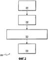
фиг.2 - иллюстрация способа определения диаграммообразующей матрицы для асимметричной системы связи с замкнутым контуром согласно настоящему изобретению;2 is an illustration of a method for determining a beam-forming matrix for an asymmetric closed loop communication system according to the present invention;
фиг.3 - иллюстрация устройства с замкнутым контуром, предназначенного для определения и подачи обратно диаграммообразующей матрицы, имеющей одинаковую мощность в асимметричной системе связи;figure 3 is an illustration of a device with a closed loop, designed to determine and feed back the beam-forming matrix having the same power in an asymmetric communication system;
фиг.4 - иллюстрация асимметричной системы связи с замкнутым контуром, модифицированной в соответствии с настоящим изобретением; и4 is an illustration of an asymmetric closed loop communication system modified in accordance with the present invention; and
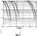
фиг.5 - иллюстрация характеристик различных методов квантования.5 is an illustration of the characteristics of various quantization methods.
В нижеследующем подробном описании делаются ссылки на сопровождающие чертежи, на которых только для примера показаны конкретные осуществления с замкнутым контуром, в которых изобретение может быть применено. Специалисту в данной области техники должно быть понятно, что они являются только примерами и не предполагаются ограничивающими настоящее изобретение в любом смысле, например, местоположение и структура отдельных элементов, раскрытых в настоящей заявке, могут быть изменены без отступления от сущности и объема изобретения, изложенных в прилагаемой формуле изобретения. То есть, подробное описание не должно использоваться ни в каком ограничивающем смысле, а объем настоящего изобретения определяется только прилагаемой формулой изобретения и эквивалентами ее, например, в передатчике может оцениваться и корректироваться Q. На чертежах одинаковые позиции везде относятся к одним и тем же или подобным функциональным элементам.In the following detailed description, reference is made to the accompanying drawings, in which, by way of example only, specific embodiments with a closed loop are shown in which the invention can be applied. A person skilled in the art should understand that they are only examples and are not intended to limit the present invention in any sense, for example, the location and structure of the individual elements disclosed in this application can be changed without departing from the essence and scope of the invention set forth in the attached claims. That is, the detailed description should not be used in any limiting sense, and the scope of the present invention is determined only by the attached claims and its equivalents, for example, Q can be estimated and adjusted in the transmitter. In the drawings, the same reference numbers everywhere refer to the same or similar functional elements.
Настоящее изобретение предоставляет ряд способов низкой сложности для получения преимущества пространственного разнесения, обеспечиваемого образованием диаграмм направленности множества передающих антенн и комбинированием множества приемных антенн. Для всех способов диаграммообразования согласно предпочтительным осуществлениям настоящего изобретения в передатчике требуется информация о канале.The present invention provides a number of low complexity methods to take advantage of spatial diversity provided by beamforming multiple transmit antennas and combining multiple receive antennas. For all beamforming methods according to preferred embodiments of the present invention, channel information is required in the transmitter.
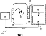
На фиг.1 показан замкнутый контур, содержащий две беспроводные станции 101, 105, которые могут быть частью беспроводной локальной сети, включающей в себя мобильные станции (портативный компьютер, персональный цифровой ассистент), и могут быть точками доступа для таких беспроводных локальных сетей. Беспроводные станции 101, 105 могут быть частью глобальной беспроводной сети и персональных беспроводных сетей. Эти станции 101, 105 могут удовлетворять требованиям стандарта беспроводной связи, такого как IEEE 802.11, или любого другого стандарта, который удовлетворяет его требованиям частично или полностью. Однако каждая из беспроводных станций 101, 105 имеет множество антенн, и в настоящем изобретении их количество предполагается асимметричным.Figure 1 shows a closed loop containing two
Имея систему диаграммообразования для множества передающих антенн и комбинирования множества приемных антенн (с разомкнутым или замкнутым контуром), при наличии N T передающих антенн и N R приемных антенн, предположим, что имеются N R передаваемых потоков данных и что диаграммообразующая матрица определена как Q. В таком случае модель сигнала имеет видHaving a beam forming system for multiple transmit antennas and combining multiple receive antennas (open or closed loop), with N T transmit antennas and N R receive antennas, suppose that there are N R transmitted data streams and that the beam-forming matrix is defined as Q. In this case, the signal model has the form
r =HQx + n , r = HQ x + n ,
где n является вектором шума, принимаемый вектор r представляет собой (N R×1)-вектор, канальная матрица Н (103) представляет собой матрицу размера (N R×N T), диаграммообразующая матрица Q представляет собой матрицу размера (N T×N R) и x является (N R×1)-вектором. Канал Н предполагается полностью известным. Передаваемый вектор представляет собой y =Qx , и он является (N T×1)-вектором. В системе OFDM упомянутая выше модель сигнала повторяется для каждого частотного бина. В частотно-избирательном канале H и Q являются различными для каждого частотного бина.where n is a noise vector, the received vector r is an ( N R × 1) -vector, the channel matrix H (103) is a size matrix ( N R × N T ), the beam-forming matrix Q is a size matrix ( N T × N R ) and x is an ( N R × 1) -vector. Channel H is assumed to be fully known. The transmitted vector is y = Q x , and it is an ( N T × 1) -vector. In the OFDM system, the above signal model is repeated for each frequency bin. In the frequency selective channel, H and Q are different for each frequency bin.
На фиг.1 показана система 100 с замкнутым контуром, и для уменьшения сложности декодирования информация о текущем состоянии канала передается между станциями 101 и 105. Каждая из станций 101 и 105 включает в себя множество антенн, соответственно N T (102i) и N R (104j), и совместно с ними образует систему 100. Полоса частот связи, используемая для этого, называется «полосой частот обратной связи» и подается обратно с приемника 105 к передатчику 101 по каналу 107 обратной связи после получения оценки канальным устройством 106 оценивания, которое представляет информацию о текущем состоянии канала с помощью диаграммообразующей матрицы Q, которая в некоторых предпочтительных осуществлениях определяется с использованием разложения по особым значениям. В передатчике 101 диаграммообразующая матрица Q используется для передачи каждого исходящего сигнала во множество пространственных каналов.1 shows a closed
Если матрица собственных векторов Р данной матрицы А не является квадратной матрицей (например, матрица ![]()
![]()
Пусть H=USV H будет разложением по особым значениям канальной матрицы Н. В таком случае оптимальным выбором для Q является Q=[ V 1 V 2 … V R], где V i является i-м столбцом матрицы V. Требование, заключающееся в том, что передаваемая мощность от каждой антенны должна быть одинаковой, трансформируется в ограничивающее условие, заключающееся в том, что каждая строка диаграммообразующей матрицы Q имеет одну и ту же мощность. Поскольку собственные векторы V i являются ортонормированными, когда R=T, то каждый из элементов передаваемого вектора y имеет одну и ту же передаваемую мощность. Однако, когда R<T, это больше не является справедливым.Let H = USV H be an expansion in the special values of the channel matrix H. In this case, the optimal choice for Q is Q = [ V 1 V 2 ... V R ], where V i is the ith column of the matrix V. The requirement that the transmitted power from each antenna should be the same is transformed into the limiting condition that each row of the matrix- forming matrix Q has the same power. Since the eigenvectors V i are orthonormal when R = T , then each of the elements of the transmitted vector y has the same transmitted power. However, when R <T, this is no longer true.
На фиг.2 показан способ 200 в соответствии с настоящим изобретением. На этапе 201 оценивают канал Н. В предпочтительном осуществлении предусматривают модифицированное устройство 300 оценивания канала/выравнивания мощности/[обратной связи]. Однако, когда для передатчика не требуется обратной связи, предусматривают только модифицированное устройство оценивания канала/выравнивания мощности. В любом случае в устройство включают память 301 и на этапе 201 в нем сохраняют Н (301.1). На этапе 202 определяют, как описано выше, диаграммообразующую матрицу Q (301.2) и сохраняют в памяти 301. Затем на этапе 203 диаграммообразующую матрицу Q (301.2) корректируют, используя один из нижеследующих методов, каждый из которых входит в состав отдельного предпочтительного осуществления настоящего изобретения, для уверенности в том, что передаваемый вектор будет иметь одинаковые компоненты мощности. Скорректированную диаграммообразующую матрицу 301.3 сохраняют в памяти 301 устройства 300.2 shows a
Метод 1: нормирование с полным перебором.Method 1: rationing with exhaustive search.
Начинают с Q=[ V 1 V 2 … V R]. Затем нормируют каждую строку Q, чтобы иметь единичную мощность. Результирующей диаграммообразующей матрицей гарантируются компоненты y с одинаковой мощностью.Start with Q = [ V 1 V 2 ... V R ]. Then each line Q is normalized to have unit power. The resulting diagram-forming matrix guarantees components y with the same power.
Метод 2: квантование только по значениям ±1±j.Method 2: quantization only by values ± 1 ± j .
И опять, как определено выше, начинают с Q. В таком случае Q1=sign[Re(Q)+jsign(Im(Q)] является диаграммообразующей матрицей, которая не только имеет компоненты с одинаковой мощностью, но, поскольку каждая компонента может иметь только 1 из 4 значений, результатом будет меньшее количество бит, используемых для обратной связи.And again, as defined above, start with Q. In this case, Q 1 = sign [Re ( Q ) + j sign (Im ( Q )] is a diagram-forming matrix that not only has components with the same power, but since each component can have only 1 of 4 values, the result will be less number of bits used for feedback.
Метод 3: оптимизация, основанная на внешней вероятности.Method 3: optimization based on external probability.
Упомянутые выше методы получения диаграммообразующей матрицы со строками одинаковой мощности не включают в себя никакого критерия оптимальности. Начнем с предположения, что каждым элементом Q является ±1±j. В таком случае критерием для выбора Q является максимизация |det(HQ)|. Поскольку имеются ![]()
![]()
Метод 4: гибридная оптимизация.Method 4: Hybrid Optimization.
В упомянутом выше методе 3 необходима оптимизация по большому числу возможностей. Дальнейшее упрощение заключается в использовании метода 2 для первого вектора, то есть в квантовании первого вектора матрицы SVD, и затем использовании метода 3 для определения других векторов. В случае 4×2 для этого требуется выполнение SVD с последующей оптимизацией по 9 возможным выборам.In the method 3 mentioned above, optimization over a large number of possibilities is necessary. A further simplification is to use method 2 for the first vector, that is, to quantize the first vector of the SVD matrix, and then use method 3 to determine other vectors. In the case of 4 × 2, this requires the implementation of SVD with subsequent optimization over 9 possible selections.
Метод 5: оптимизация в частотной области.Method 5: optimization in the frequency domain.
Если единственную диаграммообразующую матрицу выбирают для частотных бинов p каналов, то критерием оптимизации является выбор такого Q, которое максимизирует ![]()
![]()
На фиг.2 иллюстрируется способ определения диаграммообразующей матрицы Q в случае замкнутого контура, который включает в себя приемник 105 и подачу Q обратно на передатчик 101. На этапе 201 с помощью приемника оценивают состояние канала при матрице Н. Затем на этапе 202 на основании Н оценивают (как описывалось выше) диаграммообразующую матрицу Q. На этапе 203 любой из методов 1-5 настоящего изобретения используют для корректировки матрицы Q так, чтобы компоненты имели одинаковую мощность, и на этапе 204 скорректированную диаграммообразующую матрицу подают обратно на передатчик.Figure 2 illustrates a method for determining a beam-forming matrix Q in the case of a closed loop, which includes a
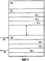
На фиг.3 показано устройство 300 согласно настоящему изобретению, предназначенное для оценивания канала и осуществления обратной связи 300 при замкнутом контуре, включающее в себя память 301 для сохранения матрицы Н состояния канала и относящихся к ней данных, 301.1, и первоначальной диаграммообразующей матрицы и относящихся к ней данных, 301.2, и корректировки диаграммообразующей матрицы и относящихся к ней данных, 310.2, в соответствии с настоящим изобретением. Устройство 300 также включает в себя компонент 302 выравнивателя мощности, который получает принимаемые сигналы 303 для канала Н и включает в себя модуль 302.1 оценивания канала для формирования на основании оценки канальной матрицы Н и сохранения ее в памяти 301 в качестве матрицы состояния канала/данных, 301.1. Компонент 302 выравнивателя мощности также включает в себя модуль 302.2 корректировки диаграммообразующей матрицы, который формирует исходную диаграммообразующую матрицу, после чего корректирует 203 исходную диаграммообразующую матрицу в соответствии с заранее выбираемым одним из методов 1-5 настоящего изобретения и сохраняет скорректированную матрицу Q и относящиеся к ней данные в памяти 301 в качестве скорректированной диаграммообразующей матрицы/данных 301.3. Наконец, компонент выравнивателя мощности включает в себя модуль 302.3 обратной связи, который подает скорректированную диаграммообразующую матрицу Q обратно в качестве сигналов 304 обратной связи по каналу 107 обратной связи к передатчику 101.FIG. 3 shows a
На фиг.4 показана асимметричная система 400 связи с замкнутым контуром, которая включает в себя по меньшей мере один передатчик 101 и приемник 105, модифицированный для сопряжения с устройством 300 оценивания канала/обратной связи, сконфигурированным в соответствии с настоящим изобретением, и получающий принимаемые сигналы 303 с передатчика 101, относящиеся к состоянию Н (103) канала. Устройство 300 оценивания канала/обратной связи оценивает канал, формирует и сохраняет канальную матрицу Н и относящиеся к ней данные в памяти 301.1, формирует и сохраняет исходную диаграммообразующую матрицу, получаемую на основании матрицы Н, в памяти 301.2, и корректирует 203 исходную диаграммообразующую матрицу в соответствии с заранее выбираемым одним из методов 1-5 настоящего изобретения, и сохраняет скорректированную диаграммообразующую матрицу Q в памяти 301.3. Наконец, с устройства 300 оценивания канала/обратной связи скорректированная диаграммообразующая матрица Q (304) подается (204) обратно к передатчику 101 по каналу 107 обратной связи. Как указывалось выше, система 400 связи может удовлетворять полностью или частично любому стандарту связи, такому как IEEE 802.11, и может быть частью беспроводной сети связи любого вида. Настоящее изобретение предназначено для применения во всех асимметричных беспроводных сетях/системах связи.4 shows an asymmetric closed
На фиг.5 показаны характеристики различных методов квантования системы 4×2 в частотно-избирательную систему с использованием кодовой модуляции с чередованием битов. Можно видеть, что особенно при более высоких скоростях (относительная скорость 5,6; 64-точечная квадратурная амплитудная модуляция) характеристики методов очень немного ухудшаются по сравнению с оптимальным диаграммообразованием с неравной мощностью передачи.Figure 5 shows the characteristics of various methods for quantizing a 4 × 2 system into a frequency selective system using bit-interleaved code modulation. It can be seen that, especially at higher speeds (relative speed 5.6; 64-point quadrature amplitude amplitude modulation), the characteristics of the methods deteriorate very slightly compared to optimal beam formation with unequal transmit power.
Хотя настоящее изобретения было описано применительно к определенным осуществлениям, а именно для замкнутых контуров, предполагается, что специалист в данной области техники представляет себе, что модификации и варианты могут быть сделаны без отступления от сущности и объема настоящего изобретения, содержащихся в прилагаемой формуле изобретения. В частности, передатчик может получать информацию из канала и осуществлять способ без необходимости какой-либо обратной связи с приемника.Although the present invention has been described with reference to certain implementations, namely for closed loops, it is assumed that one skilled in the art will recognize that modifications and variations can be made without departing from the spirit and scope of the present invention contained in the appended claims. In particular, the transmitter can receive information from the channel and implement the method without the need for any feedback from the receiver.
Claims (16)
предоставляют систему (400) беспроводной связи, имеющую NT передающих антенн (102i) и NR приемных антенн (104j), NT>NR>0;
корректируют диаграммообразующую матрицу Q (301.2) предварительно выбираемым методом так, чтобы каждая строка Q имела одну и ту же мощность; и
передают с помощью передатчика (101) вектор в качестве NR потоков данных по каналу Н (103), используя скорректированную диаграммообразующую матрицу (301.3), при этом передаваемые NR потоков данных имеют одинаковую мощность.1. A method of transmitting an asymmetric pattern-forming vector over a wireless channel H (103), comprising the steps of:
provide a wireless communication system (400) having N T transmit antennas (102 i ) and N R receive antennas (104 j ), N T > N R >0;
correct the beam-forming matrix Q (301.2) by a preselected method so that each row Q has the same power; and
transmit using the transmitter (101) the vector as N R data streams on the channel H (103) using the corrected matrix-forming matrix (301.3), while the transmitted N R data streams have the same power.
оценивают канал Н в приемнике (105);
выполняют этап корректировки в приемнике (300); и
подают (107) скорректированную диаграммообразующую матрицу обратно в передатчик (101).4. The method according to claim 3, in which the adjustment step further comprises stages in which:
evaluate channel H at the receiver (105);
performing an adjustment step at the receiver (300); and
feed (107) the corrected beam-forming matrix back to the transmitter (101).
память (301) для сохранения в ней информации (301.1-301.3) для выравнивания диаграммообразующей мощности; и
компонент (302) выравнивателя мощности для получения принимаемых сигналов (303), оценивания на основании них информации для выравнивания диаграммообразующей мощности передачи в NR потоках данных в соответствии с предварительно выбираемым методом выравнивания и сохранения ее (301.1-301.3) в упомянутой памяти.6. A beam-forming device (300) for a multi-antenna system having N T transmit antennas and N R receive antennas, wherein N T > N R > 0, comprising:
a memory (301) for storing information in it (301.1-301.3) for aligning the beam-forming power; and
a power equalizer component (302) for receiving received signals (303), evaluating information based thereon for aligning the beam-forming transmit power in N R data streams in accordance with a previously selected alignment method and storing it (301.1-301.3) in said memory.
память (301) содержит информацию (301.1) о состоянии канала, информацию (301.2) о диаграммообразовании и информацию (301.3) о скорректированном диаграммообразовании; и
компонент (302) выравнивателя мощности содержит модуль (302.1) оценивания канала для оценивания и сохранения в упомянутой памяти информации (301.1) о состоянии канала, модуль (302.2) корректировки диаграммообразующей матрицы для определения и сохранения в упомянутой памяти информации (301.2) о диаграммообразовании и корректировки и сохранения в упомянутой памяти информации (301.3) о скорректированном диаграммообразовании, предназначенной для выравнивания мощности передачи NR потоков данных.8. The device according to claim 7, in which:
the memory (301) contains information (301.1) about the state of the channel, information (301.2) about the chart formation and information (301.3) about the adjusted chart formation; and
the power equalizer component (302) contains a channel estimation module (302.1) for estimating and storing channel state information (301.1) in the mentioned memory, a beam-forming matrix adjustment module (302.2) for determining and storing in the mentioned memory information (301.2) about the waveform formation and correction and storing in said memory information (301.3) about the corrected diagramming intended to equalize the transmit power N R data streams.
по меньшей мере один приемник (105), включающий в себя NR (104j) приемных антенн, NT>NR≥1 (400);
по меньшей мере один передатчик (101), включающий в себя NT передающих антенн (102i), для диаграммообразующей передачи NR потоков данных к упомянутым NR (104j) приемным антеннам; и
по меньшей мере одно устройство (300) оценивания канала/выравнивания мощности для получения в соответствии с предварительно выбираемым методом выравнивания скорректированной диаграммообразующей матрицы, используемой по меньшей мере одним передатчиком (101), для выравнивания диаграммообразующей мощности передачи в упомянутых передаваемых NR потоках данных и сохранения (301.3) ее в памяти (301).10. The system (400) for the formation of multiple transmitting antennas and combining multiple receiving antennas, containing:
at least one receiver (105) including N R (104 j ) receiving antennas, N T > N R ≥1 (400);
at least one transmitter (101) including N T transmit antennas (102 i ) for diagrammatically transmitting N R data streams to said N R (104 j ) receive antennas; and
at least one channel estimator / power equalization device (300) for obtaining, in accordance with a preselected alignment method, the corrected beamforming matrix used by at least one transmitter (101) to align the beamforming transmit power in said N R transmitted data streams and store (301.3) her in memory (301).
NT передающих антенн (102i) для диаграммообразующей передачи вектора по каналу NR потоков данных к NR (104j) приемным антеннам, при этом NT>NR>0;
компонент (302) выравнивателя мощности определяет оценку канала и диаграммообразующую матрицу и на основании этого корректирует диаграммообразующую матрицу для выравнивания диаграммообразующей мощности передачи в NR потоках данных в соответствии с методом выравнивания с полным перебором; и
передатчик, который использует скорректированную диаграммообразующую матрицу для передачи вектора в виде NR потоков данных, имеющих одинаковую мощность.14. A beam-forming transmitter comprising:
N T transmit antennas (102 i ) for the beam-forming vector transmission on the channel N R data streams to N R (104 j ) receive antennas, with N T > N R >0;
the power equalizer component (302) determines the channel estimate and the beam-forming matrix and, on the basis of this, corrects the beam-forming matrix to align the beam-forming transmit power in N R data streams in accordance with the exhaustive matching method; and
a transmitter that uses a corrected beam-forming matrix to transmit a vector in the form of N R data streams having the same power.
NR приемных антенн (104j) для получения и комбинирования из них передачи с осуществленным диаграммообразованием вектора передатчиком (101), имеющим NT (102i) передающих антенн, по каналу NR потоков данных, при этом NT>NR>0; и
устройство (300) оценивания канала/выравнивания мощности/обратной связи для обеспечения в соответствии с предварительно выбираемым методом выравнивания скорректированной диаграммообразующей матрицы, подаваемой обратно, для использования передатчиком (101) с целью выравнивания диаграммообразующей мощности передачи в упомянутых передаваемых NR потоках данных.15. A combinational receiving device, comprising:
N R receive antennas (104 j ) for receiving and combining transmission from them with a vector diagram by a transmitter (101) having N T (102 i ) transmit antennas over a channel N R data streams, with N T > N R >0; and
a channel estimator / power equalization / feedback device (300) for providing, in accordance with a preselected alignment method, a corrected beamforming matrix fed back for use by a transmitter (101) to align beamforming transmit power in said N R transmitted data streams.
Applications Claiming Priority (4)
| Application Number | Priority Date | Filing Date | Title |
|---|---|---|---|
| US77558906P | 2006-02-22 | 2006-02-22 | |
| US60/775,589 | 2006-02-22 | ||
| US80947406P | 2006-05-30 | 2006-05-30 | |
| US60/809,474 | 2006-05-30 |
Publications (2)
| Publication Number | Publication Date |
|---|---|
| RU2008137643A RU2008137643A (en) | 2010-03-27 |
| RU2426232C2 true RU2426232C2 (en) | 2011-08-10 |
Family
ID=38137586
Family Applications (1)
| Application Number | Title | Priority Date | Filing Date |
|---|---|---|---|
| RU2008137643/09A RU2426232C2 (en) | 2006-02-22 | 2007-02-20 | System, apparatus, and method for asymmetrical beam-forming with equal-power transmission |
Country Status (12)
| Country | Link |
|---|---|
| US (1) | US8190211B2 (en) |
| EP (1) | EP1989791B1 (en) |
| JP (1) | JP5210178B2 (en) |
| KR (1) | KR101443569B1 (en) |
| AR (1) | AR059861A1 (en) |
| AU (1) | AU2007219200B2 (en) |
| BR (1) | BRPI0707993B1 (en) |
| CA (1) | CA2642893C (en) |
| MY (1) | MY153443A (en) |
| RU (1) | RU2426232C2 (en) |
| TW (1) | TWI433484B (en) |
| WO (1) | WO2007096820A1 (en) |
Families Citing this family (19)
| Publication number | Priority date | Publication date | Assignee | Title |
|---|---|---|---|---|
| US8130864B1 (en) | 2007-04-03 | 2012-03-06 | Marvell International Ltd. | System and method of beamforming with reduced feedback |
| US8165543B2 (en) * | 2007-04-25 | 2012-04-24 | Marvell World Trade Ltd. | Power amplifier adjustment for transmit beamforming in multi-antenna wireless systems |
| KR101520667B1 (en) | 2007-09-10 | 2015-05-18 | 엘지전자 주식회사 | Allocation method of pilot subcarriers in mimo system |
| WO2009084877A1 (en) * | 2007-12-28 | 2009-07-09 | Samsung Electronics Co., Ltd. | Method and apparatus for transmitting/receiving downlink data in wireless communication network |
| JP5463620B2 (en) | 2008-02-26 | 2014-04-09 | 日産自動車株式会社 | Control device for shift-by-wire failure of vehicles with automatic transmission |
| US8582672B2 (en) | 2009-02-12 | 2013-11-12 | Futurewei Technologies, Inc. | System and method for wireless communications using spatial multiplexing with incomplete channel information |
| US8644368B1 (en) | 2009-09-23 | 2014-02-04 | Marvell International Ltd. | Transparent implicit beamforming in a communication system |
| US9276722B2 (en) * | 2010-05-05 | 2016-03-01 | Qualcomm Incorporated | Expanded search space for R-PDCCH in LTE-A |
| US9071286B2 (en) * | 2011-05-26 | 2015-06-30 | Cohere Technologies, Inc. | Modulation and equalization in an orthonormal time-frequency shifting communications system |
| US8917787B2 (en) * | 2011-03-22 | 2014-12-23 | Hitachi, Ltd. | Systems and methods for creating a downlink precode for communication system with per-antenna power constraints |
| WO2012138971A2 (en) * | 2011-04-06 | 2012-10-11 | Sejent Corporation | Measuring instantaneous bit rate in a network connection |
| US9485714B2 (en) | 2011-11-09 | 2016-11-01 | Agency For Science, Technology And Research | Addressing multiple communication terminals in a wireless communication network |
| KR101284935B1 (en) | 2012-06-20 | 2013-07-10 | 한국과학기술원 | Outage-based robust beam design method for mimo interference channel with channel uncertainty |
| US9661579B1 (en) | 2013-05-03 | 2017-05-23 | Marvell International Ltd. | Per-tone power control in OFDM |
| US9843097B1 (en) | 2013-07-08 | 2017-12-12 | Marvell International Ltd. | MIMO implicit beamforming techniques |
| US9281884B2 (en) * | 2014-04-07 | 2016-03-08 | Imagination Technologies, Llc | Reordering of a beamforming matrix |
| CN105429686B (en) * | 2015-11-05 | 2018-10-12 | 江苏中兴微通信息科技有限公司 | The molding transmitting device of the asymmetric mixed-beam of divergence type and method |
| CN105306125B (en) * | 2015-11-16 | 2018-10-16 | 江苏中兴微通信息科技有限公司 | Asymmetric shared mixed-beam is molded R-T unit |
| US11228987B2 (en) * | 2020-04-09 | 2022-01-18 | Motorola Mobility Llc | Method and wireless communication device for sharing a total power budget between at least two transmitters |
Family Cites Families (7)
| Publication number | Priority date | Publication date | Assignee | Title |
|---|---|---|---|---|
| US8634481B1 (en) * | 2000-11-16 | 2014-01-21 | Alcatel Lucent | Feedback technique for wireless systems with multiple transmit and receive antennas |
| US7813440B2 (en) | 2003-01-31 | 2010-10-12 | Ntt Docomo, Inc. | Multiple-output multiple-input (MIMO) communication system, MIMO receiver and MIMO receiving method |
| JP4413540B2 (en) * | 2003-01-31 | 2010-02-10 | 株式会社エヌ・ティ・ティ・ドコモ | Multi-input multi-output propagation path signal transmission apparatus and receiving station |
| US7680461B2 (en) | 2003-11-05 | 2010-03-16 | Sony Corporation | Wireless communications system, wireless communications method, and wireless communications apparatus |
| JP4039413B2 (en) * | 2003-11-05 | 2008-01-30 | ソニー株式会社 | Wireless communication system, wireless communication method, and wireless communication apparatus |
| US7362822B2 (en) * | 2004-09-08 | 2008-04-22 | Intel Corporation | Recursive reduction of channel state feedback |
| US7539253B2 (en) | 2004-09-10 | 2009-05-26 | Intel Corporation | Interpolation in channel state feedback |
-
2007
- 2007-02-16 TW TW096106241A patent/TWI433484B/en active
- 2007-02-20 WO PCT/IB2007/050546 patent/WO2007096820A1/en active Application Filing
- 2007-02-20 BR BRPI0707993-1A patent/BRPI0707993B1/en active IP Right Grant
- 2007-02-20 KR KR1020087020245A patent/KR101443569B1/en active IP Right Grant
- 2007-02-20 JP JP2008555922A patent/JP5210178B2/en active Active
- 2007-02-20 MY MYPI20083213A patent/MY153443A/en unknown
- 2007-02-20 US US12/280,002 patent/US8190211B2/en active Active
- 2007-02-20 AR ARP070100708A patent/AR059861A1/en active IP Right Grant
- 2007-02-20 AU AU2007219200A patent/AU2007219200B2/en active Active
- 2007-02-20 RU RU2008137643/09A patent/RU2426232C2/en active
- 2007-02-20 CA CA2642893A patent/CA2642893C/en active Active
- 2007-02-20 EP EP07705922.8A patent/EP1989791B1/en active Active
Also Published As
| Publication number | Publication date |
|---|---|
| AR059861A1 (en) | 2008-05-07 |
| KR101443569B1 (en) | 2014-09-23 |
| EP1989791A1 (en) | 2008-11-12 |
| TW200742310A (en) | 2007-11-01 |
| CA2642893C (en) | 2015-06-23 |
| AU2007219200A1 (en) | 2007-08-30 |
| AU2007219200B2 (en) | 2011-02-17 |
| JP5210178B2 (en) | 2013-06-12 |
| BRPI0707993B1 (en) | 2020-02-18 |
| EP1989791B1 (en) | 2016-08-24 |
| MY153443A (en) | 2015-02-13 |
| JP2009527973A (en) | 2009-07-30 |
| US20090221241A1 (en) | 2009-09-03 |
| US8190211B2 (en) | 2012-05-29 |
| WO2007096820A1 (en) | 2007-08-30 |
| BRPI0707993A2 (en) | 2011-05-17 |
| CA2642893A1 (en) | 2007-08-30 |
| TWI433484B (en) | 2014-04-01 |
| RU2008137643A (en) | 2010-03-27 |
| KR20080098037A (en) | 2008-11-06 |
Similar Documents
| Publication | Publication Date | Title |
|---|---|---|
| RU2426232C2 (en) | System, apparatus, and method for asymmetrical beam-forming with equal-power transmission | |
| US10693535B2 (en) | Precoding in high-order MIMO | |
| US9344166B2 (en) | Methods and apparatus in a MIMO telecommunications system | |
| US9054754B2 (en) | Method and apparatus for acquiring a precoding matrix indicator and a precoding matrix | |
| US7872963B2 (en) | MIMO-OFDM system using eigenbeamforming method | |
| US7194237B2 (en) | System and method for multiple-input multiple-output (MIMO) radio communication | |
| US7542454B2 (en) | MIMO channel feedback protocols | |
| US20130040705A1 (en) | Method of Precoding with a Codebook for a Wireless System | |
| US9712215B1 (en) | System and method of beamforming with reduced feedback | |
| CN101682475B (en) | Method and apparatus for controlling multi-antenna transmission in a wireless communication network | |
| WO2017021774A2 (en) | Method and apparatus for hybrid beamforming | |
| US8649455B2 (en) | Multiple input multiple output communication system and communication method of adaptably transforming codebook | |
| CN101626265A (en) | Method for realizing downlink beam forming in wireless communication system | |
| US11258498B2 (en) | Hybrid beamforming in communication systems | |
| US8175633B2 (en) | Wireless communication apparatus, system, method, and program | |
| Bereyhi et al. | PAPR-limited precoding in massive MIMO systems with reflect-and transmit-array antennas | |
| CN101390302B (en) | System, apparatus, and method for asymmetrical beamforming with equal-power transmissions | |
| WO2021052820A1 (en) | Method and system for optimal spatial multiplexing in wireless communications systems using su-mimo techniques | |
| JP4105175B2 (en) | Wireless communication apparatus and method | |
| MX2008010756A (en) | System, apparatus, and method for asymmetrical beamforming with equal-power transmissions | |
| KR100983797B1 (en) | Apparatus and method for controlling transmission signal in multiple input single output system | |
| Zhu et al. | A Partial MRT Algorithm for Closed-Loop Spatial Multiplexing Systems with Transmit Antenna Selection |