RU2412056C2 - Laminate, method and device to produce it, and geofabric substitute - Google Patents
Laminate, method and device to produce it, and geofabric substitute Download PDFInfo
- Publication number
- RU2412056C2 RU2412056C2 RU2006128984/05A RU2006128984A RU2412056C2 RU 2412056 C2 RU2412056 C2 RU 2412056C2 RU 2006128984/05 A RU2006128984/05 A RU 2006128984/05A RU 2006128984 A RU2006128984 A RU 2006128984A RU 2412056 C2 RU2412056 C2 RU 2412056C2
- Authority
- RU
- Russia
- Prior art keywords
- layer
- corrugated
- laminate
- roll
- corrugation
- Prior art date
Links
Images


Classifications
-
- B—PERFORMING OPERATIONS; TRANSPORTING
- B32—LAYERED PRODUCTS
- B32B—LAYERED PRODUCTS, i.e. PRODUCTS BUILT-UP OF STRATA OF FLAT OR NON-FLAT, e.g. CELLULAR OR HONEYCOMB, FORM
- B32B3/00—Layered products comprising a layer with external or internal discontinuities or unevennesses, or a layer of non-planar form; Layered products having particular features of form
- B32B3/26—Layered products comprising a layer with external or internal discontinuities or unevennesses, or a layer of non-planar form; Layered products having particular features of form characterised by a particular shape of the outline of the cross-section of a continuous layer; characterised by a layer with cavities or internal voids ; characterised by an apertured layer
- B32B3/28—Layered products comprising a layer with external or internal discontinuities or unevennesses, or a layer of non-planar form; Layered products having particular features of form characterised by a particular shape of the outline of the cross-section of a continuous layer; characterised by a layer with cavities or internal voids ; characterised by an apertured layer characterised by a layer comprising a deformed thin sheet, i.e. the layer having its entire thickness deformed out of the plane, e.g. corrugated, crumpled
-
- B—PERFORMING OPERATIONS; TRANSPORTING
- B32—LAYERED PRODUCTS
- B32B—LAYERED PRODUCTS, i.e. PRODUCTS BUILT-UP OF STRATA OF FLAT OR NON-FLAT, e.g. CELLULAR OR HONEYCOMB, FORM
- B32B27/00—Layered products comprising a layer of synthetic resin
- B32B27/06—Layered products comprising a layer of synthetic resin as the main or only constituent of a layer, which is next to another layer of the same or of a different material
- B32B27/08—Layered products comprising a layer of synthetic resin as the main or only constituent of a layer, which is next to another layer of the same or of a different material of synthetic resin
-
- B—PERFORMING OPERATIONS; TRANSPORTING
- B32—LAYERED PRODUCTS
- B32B—LAYERED PRODUCTS, i.e. PRODUCTS BUILT-UP OF STRATA OF FLAT OR NON-FLAT, e.g. CELLULAR OR HONEYCOMB, FORM
- B32B27/00—Layered products comprising a layer of synthetic resin
-
- B—PERFORMING OPERATIONS; TRANSPORTING
- B32—LAYERED PRODUCTS
- B32B—LAYERED PRODUCTS, i.e. PRODUCTS BUILT-UP OF STRATA OF FLAT OR NON-FLAT, e.g. CELLULAR OR HONEYCOMB, FORM
- B32B27/00—Layered products comprising a layer of synthetic resin
- B32B27/18—Layered products comprising a layer of synthetic resin characterised by the use of special additives
- B32B27/20—Layered products comprising a layer of synthetic resin characterised by the use of special additives using fillers, pigments, thixotroping agents
-
- B—PERFORMING OPERATIONS; TRANSPORTING
- B32—LAYERED PRODUCTS
- B32B—LAYERED PRODUCTS, i.e. PRODUCTS BUILT-UP OF STRATA OF FLAT OR NON-FLAT, e.g. CELLULAR OR HONEYCOMB, FORM
- B32B27/00—Layered products comprising a layer of synthetic resin
- B32B27/32—Layered products comprising a layer of synthetic resin comprising polyolefins
-
- B—PERFORMING OPERATIONS; TRANSPORTING
- B32—LAYERED PRODUCTS
- B32B—LAYERED PRODUCTS, i.e. PRODUCTS BUILT-UP OF STRATA OF FLAT OR NON-FLAT, e.g. CELLULAR OR HONEYCOMB, FORM
- B32B37/00—Methods or apparatus for laminating, e.g. by curing or by ultrasonic bonding
- B32B37/0076—Methods or apparatus for laminating, e.g. by curing or by ultrasonic bonding characterised in that the layers are not bonded on the totality of their surfaces
-
- B—PERFORMING OPERATIONS; TRANSPORTING
- B32—LAYERED PRODUCTS
- B32B—LAYERED PRODUCTS, i.e. PRODUCTS BUILT-UP OF STRATA OF FLAT OR NON-FLAT, e.g. CELLULAR OR HONEYCOMB, FORM
- B32B7/00—Layered products characterised by the relation between layers; Layered products characterised by the relative orientation of features between layers, or by the relative values of a measurable parameter between layers, i.e. products comprising layers having different physical, chemical or physicochemical properties; Layered products characterised by the interconnection of layers
- B32B7/04—Interconnection of layers
- B32B7/12—Interconnection of layers using interposed adhesives or interposed materials with bonding properties
-
- B—PERFORMING OPERATIONS; TRANSPORTING
- B65—CONVEYING; PACKING; STORING; HANDLING THIN OR FILAMENTARY MATERIAL
- B65D—CONTAINERS FOR STORAGE OR TRANSPORT OF ARTICLES OR MATERIALS, e.g. BAGS, BARRELS, BOTTLES, BOXES, CANS, CARTONS, CRATES, DRUMS, JARS, TANKS, HOPPERS, FORWARDING CONTAINERS; ACCESSORIES, CLOSURES, OR FITTINGS THEREFOR; PACKAGING ELEMENTS; PACKAGES
- B65D65/00—Wrappers or flexible covers; Packaging materials of special type or form
- B65D65/38—Packaging materials of special type or form
- B65D65/40—Applications of laminates for particular packaging purposes
- B65D65/403—Applications of laminates for particular packaging purposes with at least one corrugated layer
-
- B—PERFORMING OPERATIONS; TRANSPORTING
- B32—LAYERED PRODUCTS
- B32B—LAYERED PRODUCTS, i.e. PRODUCTS BUILT-UP OF STRATA OF FLAT OR NON-FLAT, e.g. CELLULAR OR HONEYCOMB, FORM
- B32B2250/00—Layers arrangement
- B32B2250/24—All layers being polymeric
- B32B2250/242—All polymers belonging to those covered by group B32B27/32
-
- B—PERFORMING OPERATIONS; TRANSPORTING
- B32—LAYERED PRODUCTS
- B32B—LAYERED PRODUCTS, i.e. PRODUCTS BUILT-UP OF STRATA OF FLAT OR NON-FLAT, e.g. CELLULAR OR HONEYCOMB, FORM
- B32B2274/00—Thermoplastic elastomer material
-
- B—PERFORMING OPERATIONS; TRANSPORTING
- B32—LAYERED PRODUCTS
- B32B—LAYERED PRODUCTS, i.e. PRODUCTS BUILT-UP OF STRATA OF FLAT OR NON-FLAT, e.g. CELLULAR OR HONEYCOMB, FORM
- B32B2307/00—Properties of the layers or laminate
- B32B2307/30—Properties of the layers or laminate having particular thermal properties
- B32B2307/31—Heat sealable
-
- B—PERFORMING OPERATIONS; TRANSPORTING
- B32—LAYERED PRODUCTS
- B32B—LAYERED PRODUCTS, i.e. PRODUCTS BUILT-UP OF STRATA OF FLAT OR NON-FLAT, e.g. CELLULAR OR HONEYCOMB, FORM
- B32B2307/00—Properties of the layers or laminate
- B32B2307/40—Properties of the layers or laminate having particular optical properties
- B32B2307/402—Coloured
- B32B2307/4023—Coloured on the layer surface, e.g. ink
-
- B—PERFORMING OPERATIONS; TRANSPORTING
- B32—LAYERED PRODUCTS
- B32B—LAYERED PRODUCTS, i.e. PRODUCTS BUILT-UP OF STRATA OF FLAT OR NON-FLAT, e.g. CELLULAR OR HONEYCOMB, FORM
- B32B2307/00—Properties of the layers or laminate
- B32B2307/50—Properties of the layers or laminate having particular mechanical properties
- B32B2307/51—Elastic
-
- B—PERFORMING OPERATIONS; TRANSPORTING
- B32—LAYERED PRODUCTS
- B32B—LAYERED PRODUCTS, i.e. PRODUCTS BUILT-UP OF STRATA OF FLAT OR NON-FLAT, e.g. CELLULAR OR HONEYCOMB, FORM
- B32B2307/00—Properties of the layers or laminate
- B32B2307/50—Properties of the layers or laminate having particular mechanical properties
- B32B2307/514—Oriented
- B32B2307/516—Oriented mono-axially
-
- B—PERFORMING OPERATIONS; TRANSPORTING
- B32—LAYERED PRODUCTS
- B32B—LAYERED PRODUCTS, i.e. PRODUCTS BUILT-UP OF STRATA OF FLAT OR NON-FLAT, e.g. CELLULAR OR HONEYCOMB, FORM
- B32B2307/00—Properties of the layers or laminate
- B32B2307/50—Properties of the layers or laminate having particular mechanical properties
- B32B2307/514—Oriented
- B32B2307/518—Oriented bi-axially
-
- B—PERFORMING OPERATIONS; TRANSPORTING
- B32—LAYERED PRODUCTS
- B32B—LAYERED PRODUCTS, i.e. PRODUCTS BUILT-UP OF STRATA OF FLAT OR NON-FLAT, e.g. CELLULAR OR HONEYCOMB, FORM
- B32B2307/00—Properties of the layers or laminate
- B32B2307/50—Properties of the layers or laminate having particular mechanical properties
- B32B2307/538—Roughness
-
- B—PERFORMING OPERATIONS; TRANSPORTING
- B32—LAYERED PRODUCTS
- B32B—LAYERED PRODUCTS, i.e. PRODUCTS BUILT-UP OF STRATA OF FLAT OR NON-FLAT, e.g. CELLULAR OR HONEYCOMB, FORM
- B32B2307/00—Properties of the layers or laminate
- B32B2307/50—Properties of the layers or laminate having particular mechanical properties
- B32B2307/54—Yield strength; Tensile strength
-
- B—PERFORMING OPERATIONS; TRANSPORTING
- B32—LAYERED PRODUCTS
- B32B—LAYERED PRODUCTS, i.e. PRODUCTS BUILT-UP OF STRATA OF FLAT OR NON-FLAT, e.g. CELLULAR OR HONEYCOMB, FORM
- B32B2307/00—Properties of the layers or laminate
- B32B2307/70—Other properties
- B32B2307/712—Weather resistant
-
- B—PERFORMING OPERATIONS; TRANSPORTING
- B32—LAYERED PRODUCTS
- B32B—LAYERED PRODUCTS, i.e. PRODUCTS BUILT-UP OF STRATA OF FLAT OR NON-FLAT, e.g. CELLULAR OR HONEYCOMB, FORM
- B32B2307/00—Properties of the layers or laminate
- B32B2307/70—Other properties
- B32B2307/714—Inert, i.e. inert to chemical degradation, corrosion
- B32B2307/7145—Rot proof, resistant to bacteria, mildew, mould, fungi
-
- B—PERFORMING OPERATIONS; TRANSPORTING
- B32—LAYERED PRODUCTS
- B32B—LAYERED PRODUCTS, i.e. PRODUCTS BUILT-UP OF STRATA OF FLAT OR NON-FLAT, e.g. CELLULAR OR HONEYCOMB, FORM
- B32B2307/00—Properties of the layers or laminate
- B32B2307/70—Other properties
- B32B2307/724—Permeability to gases, adsorption
-
- B—PERFORMING OPERATIONS; TRANSPORTING
- B32—LAYERED PRODUCTS
- B32B—LAYERED PRODUCTS, i.e. PRODUCTS BUILT-UP OF STRATA OF FLAT OR NON-FLAT, e.g. CELLULAR OR HONEYCOMB, FORM
- B32B2307/00—Properties of the layers or laminate
- B32B2307/70—Other properties
- B32B2307/74—Oxygen absorber
-
- B—PERFORMING OPERATIONS; TRANSPORTING
- B32—LAYERED PRODUCTS
- B32B—LAYERED PRODUCTS, i.e. PRODUCTS BUILT-UP OF STRATA OF FLAT OR NON-FLAT, e.g. CELLULAR OR HONEYCOMB, FORM
- B32B2439/00—Containers; Receptacles
- B32B2439/40—Closed containers
- B32B2439/46—Bags
-
- B—PERFORMING OPERATIONS; TRANSPORTING
- B32—LAYERED PRODUCTS
- B32B—LAYERED PRODUCTS, i.e. PRODUCTS BUILT-UP OF STRATA OF FLAT OR NON-FLAT, e.g. CELLULAR OR HONEYCOMB, FORM
- B32B2553/00—Packaging equipment or accessories not otherwise provided for
- B32B2553/02—Shock absorbing
- B32B2553/026—Bubble films
-
- Y—GENERAL TAGGING OF NEW TECHNOLOGICAL DEVELOPMENTS; GENERAL TAGGING OF CROSS-SECTIONAL TECHNOLOGIES SPANNING OVER SEVERAL SECTIONS OF THE IPC; TECHNICAL SUBJECTS COVERED BY FORMER USPC CROSS-REFERENCE ART COLLECTIONS [XRACs] AND DIGESTS
- Y10—TECHNICAL SUBJECTS COVERED BY FORMER USPC
- Y10T—TECHNICAL SUBJECTS COVERED BY FORMER US CLASSIFICATION
- Y10T156/00—Adhesive bonding and miscellaneous chemical manufacture
- Y10T156/10—Methods of surface bonding and/or assembly therefor
- Y10T156/1002—Methods of surface bonding and/or assembly therefor with permanent bending or reshaping or surface deformation of self sustaining lamina
- Y10T156/1007—Running or continuous length work
- Y10T156/1016—Transverse corrugating
- Y10T156/102—Transverse corrugating with deformation or cutting of corrugated lamina
-
- Y—GENERAL TAGGING OF NEW TECHNOLOGICAL DEVELOPMENTS; GENERAL TAGGING OF CROSS-SECTIONAL TECHNOLOGIES SPANNING OVER SEVERAL SECTIONS OF THE IPC; TECHNICAL SUBJECTS COVERED BY FORMER USPC CROSS-REFERENCE ART COLLECTIONS [XRACs] AND DIGESTS
- Y10—TECHNICAL SUBJECTS COVERED BY FORMER USPC
- Y10T—TECHNICAL SUBJECTS COVERED BY FORMER US CLASSIFICATION
- Y10T156/00—Adhesive bonding and miscellaneous chemical manufacture
- Y10T156/10—Methods of surface bonding and/or assembly therefor
- Y10T156/1002—Methods of surface bonding and/or assembly therefor with permanent bending or reshaping or surface deformation of self sustaining lamina
- Y10T156/1025—Methods of surface bonding and/or assembly therefor with permanent bending or reshaping or surface deformation of self sustaining lamina to form undulated to corrugated sheet and securing to base with parts of shaped areas out of contact
-
- Y—GENERAL TAGGING OF NEW TECHNOLOGICAL DEVELOPMENTS; GENERAL TAGGING OF CROSS-SECTIONAL TECHNOLOGIES SPANNING OVER SEVERAL SECTIONS OF THE IPC; TECHNICAL SUBJECTS COVERED BY FORMER USPC CROSS-REFERENCE ART COLLECTIONS [XRACs] AND DIGESTS
- Y10—TECHNICAL SUBJECTS COVERED BY FORMER USPC
- Y10T—TECHNICAL SUBJECTS COVERED BY FORMER US CLASSIFICATION
- Y10T156/00—Adhesive bonding and miscellaneous chemical manufacture
- Y10T156/17—Surface bonding means and/or assemblymeans with work feeding or handling means
- Y10T156/1702—For plural parts or plural areas of single part
- Y10T156/1744—Means bringing discrete articles into assembled relationship
-
- Y—GENERAL TAGGING OF NEW TECHNOLOGICAL DEVELOPMENTS; GENERAL TAGGING OF CROSS-SECTIONAL TECHNOLOGIES SPANNING OVER SEVERAL SECTIONS OF THE IPC; TECHNICAL SUBJECTS COVERED BY FORMER USPC CROSS-REFERENCE ART COLLECTIONS [XRACs] AND DIGESTS
- Y10—TECHNICAL SUBJECTS COVERED BY FORMER USPC
- Y10T—TECHNICAL SUBJECTS COVERED BY FORMER US CLASSIFICATION
- Y10T428/00—Stock material or miscellaneous articles
- Y10T428/13—Hollow or container type article [e.g., tube, vase, etc.]
- Y10T428/1334—Nonself-supporting tubular film or bag [e.g., pouch, envelope, packet, etc.]
-
- Y—GENERAL TAGGING OF NEW TECHNOLOGICAL DEVELOPMENTS; GENERAL TAGGING OF CROSS-SECTIONAL TECHNOLOGIES SPANNING OVER SEVERAL SECTIONS OF THE IPC; TECHNICAL SUBJECTS COVERED BY FORMER USPC CROSS-REFERENCE ART COLLECTIONS [XRACs] AND DIGESTS
- Y10—TECHNICAL SUBJECTS COVERED BY FORMER USPC
- Y10T—TECHNICAL SUBJECTS COVERED BY FORMER US CLASSIFICATION
- Y10T428/00—Stock material or miscellaneous articles
- Y10T428/13—Hollow or container type article [e.g., tube, vase, etc.]
- Y10T428/1352—Polymer or resin containing [i.e., natural or synthetic]
-
- Y—GENERAL TAGGING OF NEW TECHNOLOGICAL DEVELOPMENTS; GENERAL TAGGING OF CROSS-SECTIONAL TECHNOLOGIES SPANNING OVER SEVERAL SECTIONS OF THE IPC; TECHNICAL SUBJECTS COVERED BY FORMER USPC CROSS-REFERENCE ART COLLECTIONS [XRACs] AND DIGESTS
- Y10—TECHNICAL SUBJECTS COVERED BY FORMER USPC
- Y10T—TECHNICAL SUBJECTS COVERED BY FORMER US CLASSIFICATION
- Y10T428/00—Stock material or miscellaneous articles
- Y10T428/24—Structurally defined web or sheet [e.g., overall dimension, etc.]
- Y10T428/24479—Structurally defined web or sheet [e.g., overall dimension, etc.] including variation in thickness
- Y10T428/24562—Interlaminar spaces
-
- Y—GENERAL TAGGING OF NEW TECHNOLOGICAL DEVELOPMENTS; GENERAL TAGGING OF CROSS-SECTIONAL TECHNOLOGIES SPANNING OVER SEVERAL SECTIONS OF THE IPC; TECHNICAL SUBJECTS COVERED BY FORMER USPC CROSS-REFERENCE ART COLLECTIONS [XRACs] AND DIGESTS
- Y10—TECHNICAL SUBJECTS COVERED BY FORMER USPC
- Y10T—TECHNICAL SUBJECTS COVERED BY FORMER US CLASSIFICATION
- Y10T428/00—Stock material or miscellaneous articles
- Y10T428/24—Structurally defined web or sheet [e.g., overall dimension, etc.]
- Y10T428/24479—Structurally defined web or sheet [e.g., overall dimension, etc.] including variation in thickness
- Y10T428/24612—Composite web or sheet
-
- Y—GENERAL TAGGING OF NEW TECHNOLOGICAL DEVELOPMENTS; GENERAL TAGGING OF CROSS-SECTIONAL TECHNOLOGIES SPANNING OVER SEVERAL SECTIONS OF THE IPC; TECHNICAL SUBJECTS COVERED BY FORMER USPC CROSS-REFERENCE ART COLLECTIONS [XRACs] AND DIGESTS
- Y10—TECHNICAL SUBJECTS COVERED BY FORMER USPC
- Y10T—TECHNICAL SUBJECTS COVERED BY FORMER US CLASSIFICATION
- Y10T428/00—Stock material or miscellaneous articles
- Y10T428/24—Structurally defined web or sheet [e.g., overall dimension, etc.]
- Y10T428/24628—Nonplanar uniform thickness material
- Y10T428/24669—Aligned or parallel nonplanarities
- Y10T428/24694—Parallel corrugations
-
- Y—GENERAL TAGGING OF NEW TECHNOLOGICAL DEVELOPMENTS; GENERAL TAGGING OF CROSS-SECTIONAL TECHNOLOGIES SPANNING OVER SEVERAL SECTIONS OF THE IPC; TECHNICAL SUBJECTS COVERED BY FORMER USPC CROSS-REFERENCE ART COLLECTIONS [XRACs] AND DIGESTS
- Y10—TECHNICAL SUBJECTS COVERED BY FORMER USPC
- Y10T—TECHNICAL SUBJECTS COVERED BY FORMER US CLASSIFICATION
- Y10T428/00—Stock material or miscellaneous articles
- Y10T428/24—Structurally defined web or sheet [e.g., overall dimension, etc.]
- Y10T428/24942—Structurally defined web or sheet [e.g., overall dimension, etc.] including components having same physical characteristic in differing degree
Abstract
Description
Настоящее изобретение относится к гибким ламинатам из пленок на основе термопластичных полимерных материалов для таких областей применения, где требуются относительно высокие показатели предела текучести и предела прочности при растяжении, способу и устройству для их получения.The present invention relates to flexible laminates made of films based on thermoplastic polymeric materials for such applications where relatively high yield strength and tensile strength are required, a method and apparatus for their production.
Примерами таких областей применения являются следующие: брезенты, обкладки водоемов, заменители геотканей, погодозащитные ламинаты, пленки для теплиц, промышленные мешки, упаковочные мешки и самостоящие сумки.Examples of such applications are: tarpaulins, lining for ponds, substitutes for geotextiles, weatherproof laminates, films for greenhouses, industrial bags, packaging bags and stand-alone bags.
Исходя из экономических соображений, существует растущая потребность в снижении толщины или веса квадратного метра гибкой пленки, изготовленной из термопластичного полимерного материала. Пределы частично определяются требуемыми прочностными свойствами, а частично - требуемой самонесущей способностью, т.е. жесткостью на изгиб. Эти требования в основном были удовлетворены отдельными разработками термопластичных полимерных композиций и, что касается прочности, также биаксиальной ориентацией или поперечным ламинированием пленок, каждая их которых имеет ориентацию по существу по одной оси или несбалансированную ориентацию по двум осям.For economic reasons, there is a growing need to reduce the thickness or weight per square meter of a flexible film made of a thermoplastic polymer material. The limits are partially determined by the required strength properties, and partially by the required self-supporting ability, i.e. bending rigidity. These requirements were mainly satisfied by individual developments of thermoplastic polymer compositions and, with regard to strength, also by biaxial orientation or transverse lamination of films, each of which has a substantially one axis orientation or an unbalanced two axis orientation.
С точки зрения прочности при такой ориентации и/или при осуществлении процессов поперечного ламинирования можно достичь существенных экономических выгод.From the point of view of strength with this orientation and / or in the implementation of the processes of transverse lamination can achieve significant economic benefits.
Так, например, промышленный мешок, изготовленный из экструдированной полиэтиленовой пленки наилучших целесообразных типов и предназначенный для упаковки 25 кг полиэтиленовых гранул, обычно должен иметь толщину 0,12-0,15 мм для того, чтобы удовлетворить стандартным требованиям по прочности, тогда как эту толщину можно снизить примерно до 0,07 мм за счет использования оптимально ориентированной и поперечной ламинированной пленки из полиэтилена. Однако, когда такое поперечное ламинирование осуществляют известным образом, только немного доступных типов машин для производства мешков из пленки и несколько типов машин для наполнения мешков могут работать адекватно с пленкой, которая является такой тонкой, как папиросная бумага.So, for example, an industrial bag made of extruded plastic film of the best suitable types and designed to pack 25 kg of polyethylene granules should usually have a thickness of 0.12-0.15 mm in order to meet standard strength requirements, while this thickness can be reduced to approximately 0.07 mm by using an optimally oriented and transverse laminated polyethylene film. However, when such transverse lamination is carried out in a known manner, only a few types of film bag making machines available and several types of bag filling machines can work adequately with a film that is as thin as tissue paper.
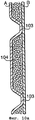
Поперечный ламинат, который помимо улучшенных прочностных свойств, достигнутых ориентированием и поперечным ламинированием, а также за счет его геометрической структуры, показывающий существенные улучшения в этом отношении, описан в более раннем патенте на имя заявителя ЕР-А-0624126. A transverse laminate, which in addition to the improved strength properties achieved by orientation and transverse lamination, as well as due to its geometric structure, showing significant improvements in this regard, is described in an earlier patent in the name of the applicant EP-A-0624126.
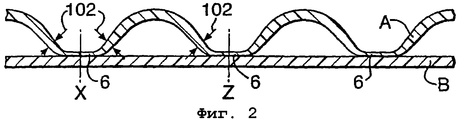
Этот поперечный ламинат слегка волновой конфигурации, в котором материал изогнутых вершин на одной или обеих сторонах ламината толще, чем везде, а материал между этими утолщенными изогнутыми вершинами обычно выпрямлен (см. фиг. 1 и 2 указанных патентных публикаций). Структура формируется при вытягивании между несколькими рядами рифленых валков в специальных условиях. Такая вытяжка также придает пленке ориентацию в поперечном направлении. Раскрытые величины шага гофров конечных продуктов составляют от 2,2 до 3,1 мм.This transverse laminate has a slightly wave configuration in which the material of the curved peaks on one or both sides of the laminate is thicker than everywhere, and the material between these thickened curved peaks is usually straightened (see Figs. 1 and 2 of these patent publications). The structure is formed by stretching between several rows of corrugated rolls in special conditions. This hood also gives the film an orientation in the transverse direction. The disclosed pitch values of the corrugations of the final products range from 2.2 to 3.1 mm.
Поперечные ламинаты согласно указанному патенту получают в промышленности с 1995 г. для изготовления промышленных мешков из комбинации высокомолекулярного полиэтилена высокой плотности (HMWHDPE) и линейного полиэтилена низкой плотности (LLDPE) с весом пленки примерно 90 гм-2, а слегка рифленая конфигурация в сочетании с утолщенными вершинами придает жесткость в одном направлении пленки, которая оказалась очень важной для эксплуатационных параметров машин для изготовления мешков из такой относительно тонкой пленки. Однако пленка с весом 70 гм-2, которая удовлетворяет требованиям по прочности, не подходит для работы на такой машине.Cross laminates according to this patent have been obtained in industry since 1995 for the manufacture of industrial bags from a combination of high molecular weight high density polyethylene (HMWHDPE) and linear low density polyethylene (LLDPE) with a film weight of about 90 gm -2 , and a slightly corrugated configuration in combination with thickened the vertices gives rigidity in one direction of the film, which turned out to be very important for the operational parameters of machines for making bags from such a relatively thin film. However, a film with a weight of 70 gm -2 , which meets the strength requirements, is not suitable for working on such a machine.
Кроме того, рифленый характер поверхности пленки делает невозможным нанесение особенно мелкой печати (что часто требуется) и также в некоторой степени снижает трение между наполненными мешками в штабеле, когда слои этого штабеля обычно укладывают из таких мешков крест-накрест.In addition, the corrugated nature of the film surface makes it impossible to apply particularly small prints (which is often required) and also to some extent reduces friction between filled bags in a stack when layers of this stack are usually stacked cross-wise from such bags.
Другим примером является сельскохозяйственный брезент (например, для защиты посевов), изготовленный из поперечного ламината ориентированных полиэтиленовых пленок весом 70 гм-2, который будет являться полноценной заменой брезенту 100 гм-2, изготовленному из тканой ленты с экструзионным покрытием, если принимают во внимание только объективные критерии. Однако, в действительности средний потребитель сельскохозяйственных брезентов делает свой выбор, в значительной степени руководствуясь легкостью обращения и внешневидовыми свойствами, и отклонит 70 гм-2 брезент вследствие его тонины, считая, что ему не хватает материала.Another example is an agricultural tarpaulin (for example, to protect crops) made of a transverse laminate of oriented polyethylene films weighing 70 gm -2 , which will be a full replacement for a
Безусловно, жесткость всегда можно увеличить целесообразным введением наполнителя (и настоящее изобретение рассматривает это как дополнительный вариант), но всегда это будет в большей или меньшей степени за счет сопротивления проколу и сопротивления разрастанию раздира, особенно под воздействием ударных нагрузок.Of course, stiffness can always be increased by the appropriate introduction of a filler (and the present invention considers this as an additional option), but it will always be more or less due to puncture resistance and resistance to tear growth, especially under the influence of shock loads.
Целью настоящего изобретения является добавить "ощущение материла" и увеличить жесткость ламинатов из пленок, по меньшей мере, в одном направлении без ухудшения восприятия ламината как двумерной структуры и, кроме того, без заметного уменьшения сопротивления проколу и сопротивления разрастанию раздира, а при желании также обеспечив хорошие печатные свойства, по меньшей мере, по одной стороне ламината.The aim of the present invention is to add a “feeling of the material” and increase the rigidity of the laminates from the films in at least one direction without compromising the perception of the laminate as a two-dimensional structure and, in addition, without noticeably reducing puncture resistance and tear growth resistance, and, if desired, also providing good printability on at least one side of the laminate.
Основная идея, лежащая в основе настоящего изобретения, заключается в том, что к ламинатам из термопластичных пленок применяют принцип рифленого картона, но таким образом, что гофрированная структура оказывается чрезвычайно тонкой ("мини-гофрированной"), так что получают ламинат, который, несмотря на структурно повышенную жесткость (по меньшей мере, в одном направлении), может удовлетворить вышеупомянутым условиям. The basic idea underlying the present invention is that the principle of corrugated cardboard is applied to thermoplastic film laminates, but in such a way that the corrugated structure is extremely thin (“mini-corrugated”), so that a laminate is obtained which, despite structurally increased rigidity (in at least one direction), can satisfy the above conditions.
Само по себе применение принципа рифленого картона к термопластичной пленке не является новым, но самая тонкая гофрированная структура, которая была раскрыта в патентной литературе, а именно в патенте США 4132581, столбец 6, строка 66, составляет 50 +/- 3 гофров на фут, что соответствует ширине шага гофра примерно 6,0 мм. Также вызывает сильные сомнения тот факт, что ширина шага меньше этой может быть достигнута способом, раскрытым в указанном патенте, в котором первый процесс связывания происходит при использовании ряда множества уплотнительных пальцев, расположенных и прикрепленных к транспортерной ленте.The application of the principle of corrugated cardboard to a thermoplastic film is not new in itself, but the thinnest corrugated structure that has been disclosed in the patent literature, namely in US Pat. No. 4,132,581,
Уплотнительные пальцы расположены в направлении, поперечном направлению перемещения (направлении машины), так что гофрирование также становится перпендикулярным этому направлению.The sealing fingers are located in a direction transverse to the direction of movement (machine direction), so that the corrugation also becomes perpendicular to this direction.
Указано, что применение способа указанного патента США относится к производству картона, и толщина указанного гофрированного слоя составляет примерно 0,004-0,025 дюймов (0,10-0,625 мм). В примере она составляет 0,018 дюймов (0,45 мм). Другими патентами, относящимися к использованию принципа гофрированного картона к термопластичной пленке для получения панелей или картона, являются следующие: патент США 3682736, патент США 3833440, патент США 3837973, Европейский патент 0325780 и WO 94/05498.It is indicated that the application of the method of said US patent relates to the manufacture of cardboard, and the thickness of said corrugated layer is about 0.004-0.025 inches (0.10-0.625 mm). In the example, it is 0.018 inches (0.45 mm). Other patents related to the use of the principle of corrugated board for thermoplastic film to produce panels or paperboard are as follows: US Pat. No. 3,682,736, US Pat. No. 3,833,440, US Pat.
Патентная выкладка Японии Hei 02-052732 раскрывает ламинаты, состоящие из гофрированной термопластичной пленки, соединенной с плоской термопластичной пленкой, которая своей другой стороной прикреплена к бумаге. (Бумага и плоский лист сначала соединяют вместе, а затем добавляют гофрированную пленку.) Гофры, которые в этом случае также являются перпендикулярными к направлению машины, расплющивают и адгезионно закрывают через определенные промежутки, так что образуется большое число наполненных воздухом полостей. Указанная область использования этого продукта - амортизационный материал, звукоизоляционный материал, тепло- и влагоизолирующий материал и декоративный стеновой материал. Толщины гофрированного листа и плоского листа не указаны, также не указан шаг гофра и длина полостей, но упоминается о том, что размеры могут быть подобраны в зависимости от области применения ламината. Однако следует понимать, что в любом случае шаг не будет меньше, чем самый малый из упомянутых в вышеуказанном патенте США 4132581 (т.е. примерно 6 мм). Одной из причин такого положения является то, что это не является преимущественным для указанных целей, за исключением декоративных, тогда как другой причиной является то, что раскрытое в патенте устройство не сможет работать при самом малом шаге (т.е. самом малом шаге зубцов шестеренчатых валков), за исключением изготовления чрезвычайно неглубокого и, в частности, бесполезного гофрирования. Это происходит вследствие того факта, что термопластичная пленка является эластичной и не является постоянно формуемой при температуре окружающей среды, что, как пояснено на чертежах, использовано в указанном способе. Если шаг зубцов мал на шестеренчатых валках, на которых осуществляют гофрирование и ламинирование, гофрированная пленка будет "выпрыгивать" из канавок на формующем и ламинирующем валке в процессе ее прохождения из места, где происходит формование гофров, в место, где происходит связывание. В этой патентной выкладке не упоминается ни о каких средствах для удерживания гофров в форме в канавках валка.Japan Patent Application Hei 02-052732 discloses laminates consisting of a corrugated thermoplastic film connected to a flat thermoplastic film that is attached to the paper with its other side. (The paper and the flat sheet are first joined together and then the corrugated film is added.) The corrugations, which in this case are also perpendicular to the direction of the machine, are flattened and adhesive closed at regular intervals, so that a large number of air-filled cavities are formed. The indicated area of use of this product is cushioning material, soundproofing material, heat and moisture insulating material and decorative wall material. The thicknesses of the corrugated sheet and the flat sheet are not indicated, nor is the step of the corrugation and the length of the cavities, but it is mentioned that the dimensions can be selected depending on the application of the laminate. However, it should be understood that in any case, the pitch will not be less than the smallest of those mentioned in the aforementioned US Pat. No. 4,132,581 (i.e., approximately 6 mm). One of the reasons for this situation is that it is not preferable for these purposes, with the exception of decorative ones, while another reason is that the device disclosed in the patent cannot work at the smallest step (i.e. the smallest step of gear teeth rolls), except for the manufacture of extremely shallow and, in particular, useless corrugation. This is due to the fact that the thermoplastic film is flexible and is not continuously moldable at ambient temperature, which, as explained in the drawings, is used in this method. If the pitch of the teeth is small on the gear rolls on which the corrugation and lamination are carried out, the corrugated film will “jump out” of the grooves on the forming and laminating roll during its passage from the place where the corrugations are formed to the place where the bonding takes place. This patent disclosure does not mention any means for holding the corrugations in shape in the grooves of the roll.
На традиционной гофрировочной машине для производства гофрированного картона имеются дорожки или щиток, чтобы поддерживать гофрированную бумагу в канавках. При температуре окружающей среды это позволяет обеспечить более легкое постоянное формование бумаги.A traditional corrugated machine for producing corrugated board has tracks or a flap to support the corrugated paper in the grooves. At ambient temperature, this allows easier continuous paper shaping.
Аналогичные дорожки или щитки на немодифицированной форме не могут быть использованы для термопластичной пленки в производственных условиях, поскольку трение о дорожку или щиток быстро создаст затор за счет нагревания полимера.Similar tracks or flaps on an unmodified form cannot be used for a thermoplastic film in a production environment, since friction against a track or flap will quickly create a blockage due to heating of the polymer.
Усовершенствованный, не создающий трения путь удерживания гофров бумаги в канавках валков известен из патента США 6139938, а именно путем поддерживания регулируемого вакуума внутри канавок (смотри фиг. 9 и 10 и столбец 7, строки 25-34). Этот патент США полностью относится к гофрированным бумажным ламинатам, имеющим особенно малый шаг гофра, тогда как о производстве гофрированных структур из термопластичных пленок не упоминается. Однако усовершенствованный способ удерживания гофров будет в действительности также применим, в зависимости от толщины пленки, к тонким гофрам термопластичной пленки. Это было установлено в связи с разработкой настоящего изобретения. Однако, как отмечено выше, в патентной выкладке Японии не раскрыты никакие средства для удерживания гофров в форме в канавках.An improved, non-friction path for holding paper corrugations in roll grooves is known from US Pat. This US patent relates fully to corrugated paper laminates having a particularly small corrugation pitch, while no production of corrugated structures from thermoplastic films is mentioned. However, an improved method for holding corrugations will in fact also apply, depending on the thickness of the film, to thin corrugations of a thermoplastic film. This has been established in connection with the development of the present invention. However, as noted above, Japan does not disclose any means to hold the corrugations in shape in the grooves.
Разработка особенно тонкой гофрированной структуры, "мини-гофров", что является целью настоящего изобретения, сделала возможным применить принцип гофрированного картона к совершенно другим областям использования, таким как области использования, упомянутые в самом начале данного описания.The development of a particularly thin corrugated structure, “mini-corrugations”, which is the purpose of the present invention, has made it possible to apply the principle of corrugated board to completely different areas of use, such as the areas of use mentioned at the very beginning of this description.
Это включает разработку новых типов оборудования на основе рифленых валков с очень малым шагом зубцов. Как будет ясно из примера, шаг 2-слойного "мини-гофрированного" ламината весом 90 гм-2 (каждый слой примерно 45 гм-2) в действительности удалось снизить до 1,0 мм за счет применения способа, который может быть осуществлен промышленно, а после усадки плоского слоя в поперечном направлении относительно гофров его удалось довести даже до 0,8 мм. Особенно за счет дополнительного использования усадки его вероятно можно еще более снизить, например, примерно до 0,5 мм. Упомянутая величина 2 × 45 гм-2 соответствует средней толщине примерно 0,074 мм (2 × 0,037 мм), если ламинат расплющить.This includes the development of new types of equipment based on corrugated rolls with a very small tooth pitch. As will be clear from the example, the step of a 2-layer “mini-corrugated” laminate weighing 90 gm -2 (each layer is approximately 45 gm -2 ) was actually reduced to 1.0 mm by applying a method that can be carried out industrially, and after shrinkage of the flat layer in the transverse direction relative to the corrugations, it was possible to bring it even up to 0.8 mm. Especially due to the additional use of shrinkage, it can probably be further reduced, for example, to about 0.5 mm. The mentioned value of 2 × 45 gm -2 corresponds to an average thickness of about 0.074 mm (2 × 0.037 mm) if the laminate is flattened.
Изобретение не ограничивается толщиной расплющенного листа примерно этой величины, но также включает, вообще говоря, мини-гофрированные ламинаты средней толщины в компактной форме, которая составляет примерно 0,3 мм или ниже. Толщину, близкую 0,03 мм или даже ниже, можно создать для специальных целей.The invention is not limited to a thickness of a flattened sheet of about this size, but also includes, generally speaking, mini-corrugated laminates of medium thickness in a compact form that is about 0.3 mm or lower. Thickness close to 0.03 mm or even lower can be created for special purposes.
Изобретение также не ограничивается использованием поперечных ламинатов ориентированных пленок. Для различных целей требуются различные комбинации прочностных свойств. Как известно, поперечные ламинаты могут быть получены при использовании целесообразных комбинаций нескольких категорий прочностных свойств, но для многих целей могут быть предпочтительны ламинаты с другими типами прочности, когда также принимается во внимание стоимость производственного процесса, и настоящее изобретение также может быть применено к таким ламинатам с другой прочностью, как дополнительно будет описано ниже по тексту.The invention is also not limited to the use of transverse laminates of oriented films. For various purposes, various combinations of strength properties are required. It is known that transverse laminates can be obtained using appropriate combinations of several categories of strength properties, but for many purposes laminates with other types of strength may be preferred when the cost of the manufacturing process is also taken into account, and the present invention can also be applied to such laminates with other strength, as will be further described below.
При таком малом шаге гофра, как 3 мм или меньше, ламинат теряет свой характер картонного материала и приобретает вид, способность к манипулированию и складыванию, аналогичные гибкой пленке (смотри пример). Он также приобретает улучшенное сопротивление к проколу, по сравнению с ламинатами, изготовленными из аналогичных слоев, но с большим шагом, поскольку в последнем случае существует высокая тенденция к разрыву слоев по отдельности вместо совместного их вклада в увеличение показателя сопротивления проколу.With such a small step of the corrugation as 3 mm or less, the laminate loses its character as a cardboard material and acquires the appearance, ability to manipulate and fold, similar to a flexible film (see example). It also acquires improved puncture resistance compared to laminates made from similar layers, but with a large step, since in the latter case there is a high tendency to tear layers separately instead of their joint contribution to an increase in puncture resistance.
"Мини-гофрированный" ламинат также обладает тем преимуществом, что на его плоскую сторону можно нанести тонкую печать и крупнозернистую печать на гофрированную сторону.The “mini-corrugated" laminate also has the advantage that a thin print and a coarse-grained print on the corrugated side can be applied to its flat side.
По сравнению с негофрированными ламинатами того же состава и того же веса на квадратный метр он дает значительно большее ощущение наличия материала вследствие повышенной жесткости в одном направлении и вследствие повышенного объема.Compared with non-corrugated laminates of the same composition and the same weight per square meter, it gives a significantly greater feeling of the presence of material due to increased stiffness in one direction and due to the increased volume.
Хорошо известно, что в случае поперечных ламинатов слабое связывание между слоями, сильное связывание или линейное связывание обеспечивает значительно лучшее сопротивление разрастанию раздира, поскольку это позволяет раздиру происходить в различных направлениях в различных слоях. Поэтому влияние надреза снижается. Если поперечный ламинат с одним гофрированным слоем будет линейно соединен, он покажет улучшенные показатели сопротивления разрастания раздира, независимо от того, каков шаг гофра короткий или длинный, однако "мини-гофрирование" останавливает раздир после очень короткого момента разрастания, что безусловно весьма преимущественно в большинстве случаев.It is well known that in the case of transverse laminates, weak bonding between layers, strong bonding or linear bonding provides significantly better resistance to tear growth, since this allows tearing to occur in different directions in different layers. Therefore, the effect of the notch is reduced. If the transverse laminate with one corrugated layer is linearly connected, it will show improved tear resistance indicators, regardless of whether the corrugation pitch is short or long, but “mini-corrugation” stops the tear after a very short moment of growth, which is certainly very predominant in most cases.
В целях упорядочения следует упомянуть, что в литературе уже описаны "мини-гофрированные" ламинаты, однако это ламинаты, у которых, по меньшей мере, гофрированный слой состоит из материала, который не является термопластичной пленкой или сборкой из термопластичных пленок.In order to streamline, it should be mentioned that “mini-corrugated” laminates have already been described in the literature, however, these are laminates in which at least the corrugated layer consists of a material that is not a thermoplastic film or an assembly of thermoplastic films.
Таким образом, патент США 6139938, упомянутый выше, имеет своей целью 3-слойный бумажный ламинат с гофрированным бумажным листом в середине и плоскими бумажными листами с каждой стороны, как нормальный гофрированный картон, однако, как заявлено, содержащий 500-600 гофров на метр, соответствующих шагу гофра 1,67-2,00 мм. Эта указанная цель состоит в улучшении печатных свойств.Thus, US Pat. No. 6,139,938, mentioned above, aims at a 3-ply paper laminate with a corrugated paper sheet in the middle and flat paper sheets on each side, like normal corrugated cardboard, however, as claimed, containing 500-600 corrugations per meter. Corresponding to the corrugation pitch 1.67-2.00 mm. This stated goal is to improve printability.
Патентная публикация Японии № 07-251004 относится к поглощающему продукту, в котором плоский лист из термопластичного синтетического волокна термически соединяют с гофрированным листом, состоящим в основном из волокон активированного углерода. Ширина шага гофра составляет 2,5-20 мм.Japan Patent Publication No. 07-251004 relates to an absorbent product in which a thermoplastic synthetic fiber flat sheet is thermally bonded to a corrugated sheet consisting mainly of activated carbon fibers. The corrugation pitch is 2.5-20 mm.
Патентная публикация Японии № 08-299385 относится к поглощающему ламинату, включающему гофрированную нетканую ткань, соединенную с одной стороны с плоским листом или пленкой, которой может быть термопластичная пленка. Между этими двумя слоями помещен водопоглощающий материал. Заявленная ширина шага гофра составляет 3-50 мм, и указано, что для поглощающего материала не будет достаточно места, если он составит меньшую величину. Продукт предназначен для пеленок и аналогичных изделий.Japanese Patent Publication No. 08-299385 relates to an absorbent laminate comprising a corrugated non-woven fabric bonded on one side to a flat sheet or film, which may be a thermoplastic film. A water-absorbing material is placed between these two layers. The declared corrugation pitch width is 3-50 mm, and it is indicated that there will not be enough space for the absorbing material if it is a smaller amount. The product is intended for diapers and similar products.
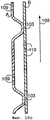
Более четко сформулированное настоящее изобретение относится к ламинату, включающему, по меньшей мере, слой (А), образованный одной или множеством пленок, и другой, образованный одной или множеством пленок слой (В), которые оба содержат в основном термопластичный полимерный материал, причем, по меньшей мере, слой А содержит ориентированный холодным способом материал, в котором А имеет волновую гофрированную конфигурацию, а В не является гофрированным, и В с первой стороны адгезионно соединен в зонах связывания с вершинами гофров на первой стороне А. Предпочтительной особенностью ламината является то, что ширина шага гофра этой конфигурации не превышает 3 мм. Данный аспект заявлен в основном патенте (ЕР 1399315), из которого выделена настоящая заявка. Использование материала холодной ориентации в А важно с точки зрения прочности продукта. Кроме того, обычно важно, чтобы адгезионное связывание было установлено через слой ламинирования так, чтобы можно было бы избежать плавления основных частей А и В в процессе ламинирования. Согласно изобретению А имеет зоны, ослабленные в твердом состоянии и вытянутые параллельно направлению гофрирования таким образом, чтобы каждая зона связывания была расположена в основном внутри одной из ослабленных зон. Эти зоны ослабления будут далее называться как "первые ослабленные зоны", поскольку могут быть также дополнительные ослабленные зоны, но это будет рассмотрено далее.A more clearly articulated present invention relates to a laminate comprising at least a layer (A) formed by one or a plurality of films, and another, a layer (B) formed by one or a plurality of films, which both comprise a substantially thermoplastic polymer material, wherein at least layer A contains a cold-oriented material in which A has a wave corrugated configuration and B is not corrugated, and B is adhesively bonded on the first side in the bonding zones to the corrugation vertices on the first thoron laminate A. A preferred feature is that the width of the corrugation pitch of this configuration does not exceed 3 mm. This aspect is claimed in the main patent (EP 1399315) from which the present application is singled out. The use of cold orientation material in A is important in terms of product strength. In addition, it is usually important that adhesive bonding is established through the lamination layer so that melting of the main parts A and B during the lamination can be avoided. According to the invention, A has zones that are weakened in the solid state and elongated parallel to the corrugation direction so that each binding zone is located mainly inside one of the weakened zones. These weakening zones will hereinafter be referred to as the “first weakened zones”, since there may also be additional weakened zones, but this will be discussed later.
В этой связи существенное ослабление А в несвязанных зонах по сравнению с толщиной А в связанных зонах будет безусловно иметь отрицательное влияние на величину сопротивления изгибу в жестком направлении (но так обычно легче сделать гофрированный ламинат). В отличие от этого сопротивление изгибу увеличивается в зависимости от средней толщины слоя А, когда каждая зона связывания попадает в основном внутрь одной из этих ослабленных зон. Ослабленные зоны также ускоряют процесс производства, как будет пояснено далее. Следует отметить, что ослабление растяжением в расплавленном состоянии снижает предел прочности при растяжении, в то время как ослабление растяжением в твердом состоянии увеличивает предел прочности при растяжении в направлении, в котором это растяжение имеет место.In this regard, a significant weakening of A in unbound zones compared to thickness A in bound zones will certainly have a negative effect on the amount of bending resistance in the hard direction (but it is usually easier to make a corrugated laminate). In contrast, bending resistance increases depending on the average thickness of layer A, when each binding zone falls mainly inside one of these weakened zones. Weakened zones also accelerate the production process, as will be explained later. It should be noted that tensile weakening in the molten state decreases tensile strength, while solid tensile weakening increases tensile strength in the direction in which this stretching takes place.
I здесь идентифицирует ламинат, включающий слои А и В, причем каждый "слой" может состоять из одной или более "пленок", обычно экструдированных пленок, и каждая экструдированная пленка может и обычно будет состоять из нескольких коэкструдированных "слоев". Таким образом, "слой ламинирования", через который происходит связывание, обычно будет представлять коэкструдированный слой, однако это может быть и тонкая пленка, нанесенная традиционным способом экструзионного ламинирования.I here identifies a laminate comprising layers A and B, wherein each “layer” may consist of one or more “films”, typically extruded films, and each extruded film may and usually will consist of several coextruded “layers”. Thus, the “lamination layer” through which the bonding takes place will usually be a coextruded layer, however, it may also be a thin film deposited by a conventional extrusion lamination process.
Хотя в качестве целесообразной величины, отличающей продукт согласно изобретению от гофрированного картонного материала, выбрана величина верхнего предела шага гофра 3 мм, но обычно лучше поддерживать шаг гофра в пределах 2,5 мм, предпочтительно - 2 мм и более предпочтительно - 1,5 мм. Как уже упомянуто и показано в примере, можно реализовать величину шага 1,0 мм, а при использовании усадки после ламинирования - даже 0,8 мм.Although the upper limit value of the corrugation pitch is 3 mm, it is generally preferred to keep the corrugation pitch within 2.5 mm, preferably 2 mm, and more preferably 1.5 mm, as the appropriate value for distinguishing the product according to the invention from the corrugated cardboard material. As already mentioned and shown in the example, it is possible to realize a step size of 1.0 mm, and when using shrinkage after lamination, even 0.8 mm.
Как явствует из вступительной части, использование настоящего изобретения предназначено главным образом для регулирования прочности пленки. Это необязательно означает хорошую прочность во всех направлениях; в отличие от этого, существуют случаи, например, в строительных мешках, когда основное внимание должно быть направлено на прочность в одном направлении, в сочетании с определенным сопротивлением проколу и разрастанию раздира. Как пример, обычный промышленный мешок из пленки толщиной 0,160 мм, изготовленный из смеси 90% LDPE и 10% LLDPE, обычно будет показывать в продольном направлении силу текучести 20 Нсм-1, т.е. напряжение текучести 12,5 МПа, а в поперечном направлении показывает силу текучести 16 Нсм-1, т.е. напряжение при текучести 10,0 МПа.As appears from the introduction, the use of the present invention is intended primarily to control film strength. This does not necessarily mean good strength in all directions; in contrast, there are cases, for example, in construction bags, where the main focus should be on strength in one direction, in combination with a certain resistance to puncture and tear growth. As an example, a typical industrial bag made of 0.160 mm film made from a mixture of 90% LDPE and 10% LLDPE will usually show a yield strength of 20 Ncm -1 in the longitudinal direction, i.e. yield strength 12.5 MPa, and in the transverse direction shows a yield strength of 16 Ncm -1 , i.e. yield stress 10.0 MPa.
Материал из поперечно ламинированной пленки средней толщиной 0,086 мм для термосварных мешков, разработанный изобретателем настоящего изобретения и производимый в соответствии с вышеуказанным Европейским патентом № 0624126, показывает в своем самом прочном направлении силу текучести 20 Нсм-1, т.е. 23 МПа, и в своем самом слабом направлении - силу текучести 17 Нсм-1, т.е. напряжение при текучести 20 МПа.The material from a transversely laminated film with an average thickness of 0.086 mm for heat sealing bags, developed by the inventor of the present invention and produced in accordance with the aforementioned European Patent No. 0624126, shows in its strongest direction a yield strength of 20 Ncm -1 , i.e. 23 MPa, and in its weakest direction - yield strength 17 Ncm -1 , i.e. yield stress 20 MPa.
Поскольку настоящее изобретение в принципе относится к гибким ламинатам для областей использования, где требуется относительно высокая прочность, хотя основное внимание в изобретении делается на жесткость, ощущение и внешний вид, напряжение при текучести ламината в его самом прочном направлении обычно будет составлять не менее 15 МПа, предпочтительно не менее 25 МПа. Соответственно, предел прочности при растяжении составляет примерно удвоенные указанные величины или больше. Здесь площадь поперечного сечения в мм2 основана только на твердом материале, не включая площади, занимаемой воздухом, и она составляет среднюю величину, принимая во внимание, что слой А может иметь ослабленные зоны.Since the present invention basically relates to flexible laminates for applications where relatively high strength is required, although the invention focuses on stiffness, sensation and appearance, the yield stress of a laminate in its strongest direction will usually be at least 15 MPa, preferably not less than 25 MPa. Accordingly, the tensile strength is approximately double the indicated values or more. Here, the cross-sectional area in mm 2 is based only on solid material, not including the area occupied by air, and it is an average value, taking into account that layer A may have weakened zones.
Упомянутое здесь напряжение при текучести относится к испытаниям на растяжение при скорости растяжения 500% в минуту. Их определяют по кривым нагрузка/удлинение. Эти кривые начинаются с линейной части согласно закону Гука, а затем начинают отклоняться от линейности, хотя деформация остается эластичной. В принципе напряжением при текучести должно быть напряжение, при котором деформация становится постоянной, но эту критическую величину, которая зависит от скорости, практически невозможно определить. Путь, которым на практике обычно определяют предел текучести при растяжении, а также считают его определенным в соответствии с настоящим изобретением, следующий:The yield stress mentioned here refers to tensile tests at a tensile speed of 500% per minute. They are determined by the load / elongation curves. These curves start from the linear part according to Hooke's law, and then begin to deviate from linearity, although the deformation remains elastic. In principle, the yield stress should be the stress at which the deformation becomes constant, but this critical value, which depends on the speed, is almost impossible to determine. The way in which the tensile yield strength is usually determined in practice, and also considered to be defined in accordance with the present invention, is as follows:
В случае, когда напряжение достигает относительного максимума, затем остается постоянным или снижается под действием сохраняющегося удлинения, затем вновь увеличивается до тех пор, пока не наступает разрыв, относительный максимум напряжения считают пределом текучести при растяжении. Образец также может разорваться в этой точке, тогда предел текучести при растяжении равен относительному напряжению при растяжении. Однако, если напряжение продолжает увеличиваться под действием удлинения, но со значительно меньшим увеличением напряжения на один процент удлинения, то кривую нагрузка/удлинение после течения, и после того, как она практически превращается в прямую линию, экстраполируют назад до пересечения с линией, которая представляет часть кривой растяжения, соответствующей закону Гука. Напряжение в точке пересечения двух линий определяют как предел текучести при растяжении.In the case when the stress reaches a relative maximum, then remains constant or decreases under the influence of the remaining elongation, then increases again until a break occurs, the relative maximum stress is considered the tensile strength. The sample can also burst at this point, then the yield strength under tension is equal to the relative tensile stress. However, if the stress continues to increase under the influence of elongation, but with a much smaller increase in stress by one percent elongation, then the load / elongation curve after flow, and after it practically turns into a straight line, is extrapolated back to the intersection with the line that represents part of the tensile curve corresponding to Hooke's law. The stress at the intersection of two lines is defined as the tensile strength.
Один из вариантов осуществления настоящего изобретения отличается тем, что слой А по выбору полимерного материала, по введенному наполнителю или по ориентации, в пределах несвязанных зон показывает среднее напряжение при течении параллельно направлению гофрирования, которое, когда его определяют, как пояснено выше, составляет не менее 30 Нмм-2 (площадь поперечного сечения только слоя А), предпочтительно - не менее 50 Нмм-2 и более предпочтительно - не менее 75 Нмм-2.One of the embodiments of the present invention is characterized in that layer A, according to the choice of a polymeric material, according to the introduced filler or by orientation, within unconnected zones, shows the average stress when flowing parallel to the corrugation direction, which, when determined, as explained above, is not less than 30 Nmm -2 (cross-sectional area of layer A only), preferably not less than 50 Nmm -2 and more preferably not less than 75 Nmm -2 .
Как уже упоминалось, А предпочтительно ослаблен в твердом состоянии в зонах ("первых ослабленных зонах") и каждая зона связывания расположена главным образом внутри первой ослабленной зоны. Эти зоны следует рассматривать как определяемые положениями, в которых толщина А составляет среднюю величину между самой низкой толщиной А внутри первой ослабленной зоны и самой высокой толщиной А внутри соседней несвязанной зоны.As already mentioned, A is preferably weakened in the solid state in the zones ("first weakened zones") and each binding zone is located mainly inside the first weakened zone. These zones should be considered as determined by the provisions in which the thickness A is the average value between the lowest thickness A inside the first weakened zone and the highest thickness A inside the adjacent unbound zone.
Другой важный вариант осуществления настоящего изобретения отличается тем, что А внутри каждой несвязанной зоны и вне первой ослабленной зоны, если такая зона существует (определяется, как описано выше), молекулярно ориентирована главным образом в направлении, параллельном направлению гофрирования или направлению, близкому к последнему, как установлено испытаниями на усадку. Такие испытания осуществляют обычным способом. В этой связи компонент ориентации в А, перпендикулярный направлению гофров, не будет вносить вклада в величину напряжения при течении ни в каком направлении, но скажется на некоторых других прочностных свойствах. Another important embodiment of the present invention is characterized in that A inside each unbound zone and outside the first weakened zone, if such a zone exists (defined as described above), is molecularly oriented mainly in a direction parallel to the corrugation direction or close to the last, as established by shrink tests. Such tests are carried out in the usual way. In this regard, the orientation component in A, perpendicular to the direction of the corrugations, will not contribute to the magnitude of the stress during flow in any direction, but will affect some other strength properties.
Предпочтительное ограничение растяжения каждой первой ослабленной зоны - предпочтительное с точки зрения жесткости в одном направлении - определено в пункте 2 формулы изобретения, а предпочтительные толщины этих зон определены в пункте 4 формулы изобретения.The preferred limitation of the stretching of each first weakened zone — preferred in terms of stiffness in one direction — is defined in
Дополнительно к первым ослабленным зонам может оказаться весьма преимущественным иметь вторую ослабленную в твердом состоянии зону (далее по тексту называемую второй ослабленной зоной) между каждой парой соседних первых ослабленных зон. Эти вторые ослабленные зоны должны быть уже, чем первые ослабленные зоны - предпочтительно как можно более узкие, но также ослабленные, так что толщина А в зоне должна быть возможно более малой - и быть расположены на вершинах гофров А на стороне, противоположной связанным зонам. Они действуют как "шарниры", и если они сделаны узкими и достаточно глубокими, они улучшают жесткость, поскольку поперечное сечение А становится зигзагообразным вместо того, чтобы быть равномерно волновым (как описано далее в связи с фигурой 3) и поэтому А и В образуют треугольные структуры. Они также значительно ускоряют производственный процесс, что пояснено ниже.In addition to the first weakened zones, it may be very advantageous to have a second solid-weakened zone (hereinafter referred to as the second weakened zone) between each pair of adjacent first weakened zones. These second weakened zones should be narrower than the first weakened zones - preferably as narrow as possible, but also weakened so that the thickness A in the zone should be as small as possible - and should be located on the tops of the corrugations A on the side opposite to the connected zones. They act as “hinges,” and if they are made narrow and deep enough, they improve rigidity since the cross section A becomes zigzag instead of being uniformly wave (as described further in connection with figure 3) and therefore A and B form triangular structure. They also significantly speed up the production process, as explained below.
Помимо усовершенствований жесткости, вызванных первой и второй ослабленными зонами (усовершенствования усматриваются относительно средней толщины А), каждый набор зон также обычно улучшает сопротивление воздействию ударных нагрузок, т.е. они обычно улучшают ударопрочность, сопротивление проколу при ударе и сопротивление разрастанию раздира при ударе. Это обусловлено тем, что начинается растяжение (или дальнейшее растяжение, если А уже растянута) и это растяжение обычно имеет тенденцию к росту под действием ударных нагрузок, при этом первая и вторая ослабленные зоны действуют как амортизаторы удара.In addition to the stiffness improvements caused by the first and second weakened zones (improvements are seen with respect to the average thickness A), each set of zones also usually improves resistance to impact loads, i.e. they usually improve impact resistance, puncture resistance upon impact, and tear growth resistance upon impact. This is because stretching begins (or further stretching if A is already stretched) and this stretching usually tends to increase under the influence of shock loads, while the first and second weakened zones act as shock absorbers.
Обычно величина шага каждого гофра, включая соседнюю зону связывания, не должна превышать самую большую толщину А внутри гофра в 50 раз, предпочтительно - не более чем в 40 раз и более предпочтительно - не более чем в 30 раз указанной толщины. Как пример, если самая большая толщина А составляет 0,037 мм, как в рабочем примере, представленном ниже, упомянутые величины соответствуют величинам шагов гофров 1,85; 1,48 и 1,11 мм соответственно.Typically, the pitch of each corrugation, including the adjacent bonding zone, should not exceed the largest thickness A inside the corrugation by 50 times, preferably not more than 40 times, and more preferably not more than 30 times the specified thickness. As an example, if the largest thickness A is 0.037 mm, as in the working example below, the mentioned values correspond to the corrugation pitch values of 1.85; 1.48 and 1.11 mm, respectively.
Для того чтобы "объединить" слои друг с другом удобным образом в целях упрочнения, ширина каждой зоны связывания обычно должна быть не менее чем 15%, предпочтительно - не менее чем 20% и более предпочтительно - не менее чем 30% величины шага гофра, а для того, чтобы достичь значительного эффекта гофрирования, ширина каждой несвязанной зоны А, измеренная между двумя соседними связанными зонами вдоль ее изогнутой поверхности, предпочтительно должна быть не менее чем на 10%, предпочтительно - не менее чем на 20% длиннее, чем соответствующее линейное расстояние. Это является мерой глубины гофров. In order to “combine” the layers with each other in a convenient way for hardening, the width of each bonding zone should usually be at least 15%, preferably at least 20% and more preferably at least 30% of the corrugation pitch, and in order to achieve a significant corrugation effect, the width of each unbound zone A, measured between two adjacent connected zones along its curved surface, should preferably be at least 10%, preferably at least 20% longer than the corresponding linear dimension standing. This is a measure of the depth of the corrugations.
Для многих целей, например, когда требуется повышенная жесткость против изгиба во всех направлениях, может быть использована негофрированная однослойная или многослойная пленка С на другой стороне А, которая расположена напротив В, как определено в пункте 17 формулы изобретения.For many purposes, for example, when increased rigidity against bending in all directions is required, a non-corrugated single-layer or multilayer film C on the other side A, which is opposite B, as defined in paragraph 17 of the claims, can be used.
Гофрированная наружная поверхность на мешке имеет, как отмечено выше, недостаток, а именно в связи с нанесением печати и штабелирования наполненных мешков. Однако есть изделия, в которых специальная шероховатость гофрированной поверхности может быть весьма преимущественной при использовании, например в матах. Для таких изделий может оказаться преимущественным иметь одно- или многослойные слои (А) и (D), ламинированные к двум противоположным сторонам негофрированной одно- или многослойной пленки (В), как определено в пункте 18 формулы изобретения.The corrugated outer surface of the bag has, as noted above, a drawback, namely in connection with printing and stacking of the filled bags. However, there are products in which the special roughness of the corrugated surface can be very advantageous when used, for example, in mats. For such products, it may be advantageous to have single or multi-layer layers (A) and (D) laminated to two opposite sides of a non-corrugated single or multi-layer film (B), as defined in claim 18.
Пленки А, В, С и D обычно будут состоять из полиолефина и их обычно будут получать способом, который включает экструзию. Как правило, это будет процесс коэкструзии, с помощью которого ламинированные слои и необязательно термосварные слои соединяют с основным телом пленки.Films A, B, C, and D will typically consist of a polyolefin and will typically be prepared by a process that involves extrusion. Typically, this will be a co-extrusion process by which laminated layers and optionally heat-sealed layers are connected to the main body of the film.
По меньшей мере, некоторые из гофров можно расплющить через расположенные продольно промежутки и предпочтительно соединить по всей ширине каждого гофра с расплющенными участками с образованием из гофров ряда узких, закрытых, продольных карманов. Предпочтительно расплющенные участки ряда расположенных рядом гофров или всех гофров образуют серии линий, расположенных в направлении, обратном продольному направлению гофров. Это может создать внешний вид гофрированному ламинату и ощущение большей схожести с текстилем, почти впечатление тканой структуры, и может обеспечить большую гибкость в направлении, которое в противоположность является жестким, без потери ощущения объема и материла. Расплющивание также может быть использовано для создания предпочтительных участков для изгиба.At least some of the corrugations can be flattened out at longitudinally spaced intervals and it is preferable to connect across the entire width of each corrugation with flattened sections to form a series of narrow, closed, longitudinal pockets from the corrugations. Preferably, the flattened portions of a series of adjacent corrugations or all corrugations form a series of lines located in a direction opposite to the longitudinal direction of the corrugations. This can create the appearance of a corrugated laminate and a feeling of greater similarity with textiles, almost the impression of a woven structure, and can provide greater flexibility in the direction that, in contrast, is tough, without losing the sense of volume and material. Flattening can also be used to create preferred sections for bending.
Дальнейшее описание различных вариантов осуществления изобретения в части продукта и конкретных областей использования будет дано после описания способа.Further description of the various embodiments of the invention in terms of the product and specific areas of use will be given after the description of the method.
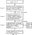
В соответствии с представленной выше характеристикой ламината согласно настоящему изобретению способ получения, который происходит при использовании рифленого валка для формования гофров, а также при использовании рифленого валка для ламинирования под действием тепла и давления (которым в некоторых случаях может быть тот же рифленый валок), отличается тем, что перед процессом связывания А находится в твердом состоянии, растянутый в узких зонах с образованием первых ослабленных зон, расположенных параллельно выбранному направлению гофрирования, причем вытяжка по существу перпендикулярна этому направлению и осуществляется между рядом рифленых валков, отличных от рифленого валка для ламинирования, причем рифленый валок для ламинирования скоординирован с набором рифленых валков для вытяжки таким образом, что каждая зона связывания становится по существу расположенной внутри первой ослабленной зоны. Для предпочтительного ламината, в котором шаг гофра составляет не более 3 мм, деление на валке, который обеспечивает ламинирование, составляет не более 3 мм. Новый способ согласно изобретению представляет собой способ, определенный в пункте 36 формулы изобретения. Новое устройство, подходящее для осуществления способа, представляет собой устройство, определенное в пункте 60 формулы изобретения.In accordance with the above characteristic of the laminate according to the present invention, the production method that occurs when using a corrugated roll for forming corrugations, and also when using a corrugated roll for lamination under the influence of heat and pressure (which in some cases may be the same corrugated roll), the fact that before the binding process A is in a solid state, stretched in narrow zones with the formation of the first weakened zones parallel to the chosen direction of th friction, and the drawing is essentially perpendicular to this direction and is carried out between a number of corrugated rolls other than a corrugated roll for lamination, and the corrugated roll for lamination is coordinated with a set of corrugated rolls for drawing so that each bonding zone becomes essentially located inside the first weakened zone . For a preferred laminate in which the corrugation pitch is not more than 3 mm, the division on the roll that provides lamination is not more than 3 mm. The new method according to the invention is the method defined in paragraph 36 of the claims. A new device suitable for implementing the method is the device defined in paragraph 60 of the claims.
В основном патенте, из которого выделена настоящая заявка, заявлены способы и устройства для получения ламината с шагом гофра менее чем 3 мм, причем первые ослабленные зоны являются предпочтительными, а не существенными признаками этих объектов согласно основному патенту. Описание указанного патента включено сюда в том виде, как оно было подано.In the main patent from which the present application is isolated, methods and devices for producing a laminate with a corrugation pitch of less than 3 mm are claimed, the first weakened zones being preferred rather than essential features of these objects according to the main patent. A description of the said patent is included here in the form in which it was filed.
Устройство может быть адаптировано либо к производству гофров перпендикулярно направлению машины, как в обычном производстве гофрированных ламинатов, либо по существу параллельно направлению машины. Это будет определено ниже.The device can be adapted either to the production of corrugations perpendicular to the direction of the machine, as in the usual production of corrugated laminates, or essentially parallel to the direction of the machine. This will be defined below.
Обычно связывание осуществляют через слой ламинирования (полученный методом ламинирования коэкструзией или экструзией) для того, чтобы избежать ослабления.Typically, bonding is carried out through a lamination layer (obtained by lamination by coextrusion or extrusion) in order to avoid weakening.
"Вторые ослабленные зоны", которые описаны выше при описании продукта, могут быть получены растяжением между дополнительным рядом рифленых валков, целесообразно координированных с рифлеными валками, с помощью которых получают первые ослабленные зоны. The "second weakened zones", which are described above in the description of the product, can be obtained by stretching between an additional row of corrugated rolls, which are expediently coordinated with the corrugated rolls, with which the first weakened zones are obtained.
Преимущества первых и вторых ослабленных зон в связи со свойствами продукта уже пояснены. Для осуществления способа первые ослабленные линии позволяют увеличить скорость и поэтому улучшить технико-экономические показатели, поскольку зоны в слое А, которые подлежат связыванию, получаются тоньше и поэтому требуют меньшего времени нагрева в процессе приложения тепла перед связыванием. Кроме того, первые ослабленные зоны и, в частности, комбинация первой и второй ослабленных зон может значительно улучшить способ, действуя как "шарниры" в слое А. В устройстве того типа, в котором рифленый валок для ламинирования имеет канавки, которые обычно параллельны его осям, такие "шарниры" позволяют направить даже относительно тяжелый А-слой в тонкие канавки. В устройстве такого типа, в котором канавки являются круговыми или спиральными, но в любом случае приблизительно перпендикулярными оси валка, "шарниры" помогают держать слой А "в треке" в процессе его прохождения от рифленого валка к рифленому валку, другими словами, "шарниры" помогают координировать действие рифленого валка для ламинирования с действием предшествующего ряда или рядов рифленых валков, которые образуют гофр при одновременном поперечном растяжении.The advantages of the first and second weakened zones in connection with the properties of the product have already been explained. To implement the method, the first weakened lines allow to increase the speed and therefore improve technical and economic indicators, since the zones in layer A that are to be bonded are thinner and therefore require less heating time during the application of heat before bonding. In addition, the first weakened zones and, in particular, the combination of the first and second weakened zones can significantly improve the method by acting as “hinges” in layer A. In a device of the type in which the corrugated roll for lamination has grooves that are usually parallel to its axes , such “hinges” even direct a relatively heavy A-layer into thin grooves. In a device of this type in which the grooves are circular or spiral, but in any case approximately perpendicular to the axis of the roll, the “hinges” help to keep layer A “in the track” as it passes from the corrugated roll to the corrugated roll, in other words, “hinges” help coordinate the action of the corrugated roll for lamination with the action of the previous row or rows of corrugated rolls that form corrugations with simultaneous transverse stretching.
Хотя с точки зрения нормального использования изобретения важно, чтобы в таких областях применения, как гибкая пленка, деление на рифленом валке, который осуществляет ламинирование по вершинам гофра, было не более чем 3 мм, обычно рекомендуют устанавливать его не более чем 2,5 мм, предпочтительно - не более чем 2,0 мм и более предпочтительно - не более чем 1,5 мм.Although from the point of view of the normal use of the invention it is important that in applications such as flexible film, the division on the corrugated roll, which laminates along the corrugation tops, is no more than 3 mm, it is usually recommended to install it no more than 2.5 mm, preferably not more than 2.0 mm and more preferably not more than 1.5 mm.
Пленка или пленки, используемые для слоя А, предпочтительно перед формированием рифленой конфигурации и перед получением первой и второй ослабленных зон (если такие зоны формируются), ориентируют в одном или обоих направлениях, причем образующееся основное направление ориентации находится в направлении, которое выбрано как направление гофрирования. Это можно осуществить с помощью сильной ориентации из расплава или предпочтительно альтернативно или дополнительно, известными методами растяжения, осуществляемыми в твердом состоянии. Если способ предназначен для получения гофров по существу параллельно направлению машины, то это будет обычно продольным процессом ориентации, что упрощает ситуацию, а если способ предназначен для получения гофров по существу перпендикулярно направлению машины, то это будет процесс поперечной ориентации, который значительно сложнее осуществить, и он обычно требует дорогостоящего оборудования. Отмечено, что ни одна из двух ближайших ссылок, т.е. патент США 4132581 и патентная заявка Японии Hei 02-052732, не содержит раскрытия изобретения, которое бы указывало, что слой А должен быть ориентирован в направлении, по существу параллельном гофрам. В этих двух публикациях гофры образуются в поперечном направлении, и поэтому возникла мысль, что было бы естественно упомянуть здесь об использовании поперечно ориентированной пленки, поскольку без осуществления специальных стадий пленку нельзя сформовать таким образом ни экструзией, ни методом литья.The film or films used for layer A, preferably before forming a corrugated configuration and before receiving the first and second weakened zones (if such zones are formed), are oriented in one or both directions, and the resulting main orientation direction is in a direction that is selected as the corrugation direction . This can be done using strong melt orientation, or preferably alternatively or additionally, by known solid stretching methods. If the method is intended to obtain corrugations essentially parallel to the direction of the machine, then this will usually be a longitudinal orientation process, which simplifies the situation, and if the method is intended to obtain corrugations essentially perpendicular to the direction of the machine, it will be a process of lateral orientation, which is much more difficult to implement, and it usually requires expensive equipment. It is noted that none of the two nearest links, i.e. US patent 4132581 and Japanese patent application Hei 02-052732, does not contain a disclosure of the invention, which would indicate that the layer And should be oriented in a direction essentially parallel to the corrugation. In these two publications, the corrugations are formed in the transverse direction, and therefore the idea arose that it would be natural to mention here the use of a transversely oriented film, since without special steps the film cannot be formed in this way either by extrusion or by casting.
В связи с рассмотрением продукта, уже описано, что дополнительный негофрированный слой (С), образованный одной пленкой или множеством пленок из термопластичного полимерного материала одновременно с или после связывания В с А, может быть адгезионно соединен с вершинами гофров А на второй стороне А. Другая ценная возможность заключается в том, что путем, аналогичным формованию и применению А, получают второй слой (D), образованный одной или множеством пленок и имеющий волновую конфигурацию гофра с величиной шага предпочтительно не более 3 мм, а вершины гофров на одной стороне D ламинируют со второй стороной В одновременно с или после ламинирования В с А.In connection with the consideration of the product, it has already been described that an additional non-corrugated layer (C) formed by one film or a plurality of films of a thermoplastic polymer material simultaneously with or after binding B to A can be adhesively bonded to the corrugation tops A on the second side A. Another a valuable opportunity lies in the fact that in a manner analogous to the molding and application of A, a second layer (D) is formed, formed by one or a plurality of films and having a wave configuration of a corrugation with a step size of preferably not more than 3 mm, and the corrugation tops on one side D are laminated with the second side B simultaneously with or after lamination B with A.
В большинстве областей применения изобретения слои, образованные одной или множеством пленок, должны состоять в основном из полиолефина и должны быть получены способом, предусматривающим применение экструзии. Кроме того, пленки, составляющие слои, должны быть изготовлены обычно коэкструзией, при которой коэкструдируемые поверхностные слои позволяют осуществить ламинирование без какого-либо плавления основного тела пленок.In most applications of the invention, the layers formed by one or a plurality of films should consist mainly of a polyolefin and should be obtained by a method involving the use of extrusion. In addition, the films constituting the layers should usually be made by coextrusion, in which coextruded surface layers allow lamination without any melting of the main body of the films.
Как видно из описания продукта, некоторые гофры, по меньшей мере, могут быть расплющены после ламинирования. Это делается через интервалы, предпочтительно под действием тепла и давления, достаточных для связывания всех пленок друг с другом в ламинат, так что гофры с соседним пленочным материалом образуют тонкие продолговатые карманы, закрытые с каждого конца. Расплющивание может быть осуществлено с помощью прутков или выступов, продольное направление которых расположено поперечно направлению гофров и каждый из которых покрывает ряд гофров, необязательно по полной ширине ламината.As can be seen from the product description, some corrugations, at least, can be flattened after lamination. This is done at intervals, preferably under the influence of heat and pressure, sufficient to bind all the films to each other in the laminate, so that the corrugations with the adjacent film material form thin elongated pockets closed at each end. Flattening can be carried out using rods or protrusions, the longitudinal direction of which is transverse to the direction of the corrugations and each of which covers a number of corrugations, not necessarily the full width of the laminate.
Целесообразно четкое образование первых ослабленных зон может быть осуществлено, по меньшей мере, частично созданием на вершинах зубцов на рифленом растягивающем валке, предназначенном для получения полос, с температурой, которая выше, чем температура вершин зубцов на другом рифленом растягивающем валке, и/или созданием на вершинах зубцов на рифленом растягивающем валке, предназначенном для получения полос, с радиусом кривизны меньше, чем радиус кривизны вершин зубцов на совмещающем рифленом растягивающем валке. Преимущественная ориентация главным образом в направлении, почти параллельном гофрированию, и/или высокий коэффициент эластичности (В) слоя А также являются эффективными средствами для получения первых ослабленных зон с четкими границами.It is advisable that the first weakened zones are clearly formed, at least partially, by creating on the tops of the teeth on a corrugated tensile roll intended to produce strips with a temperature that is higher than the temperature of the tips of the teeth on another corrugated stretching roller, and / or by creating the tops of the teeth on a corrugated tensile roll designed to produce strips with a radius of curvature less than the radius of curvature of the tops of the teeth on a combining corrugated tensile roll. The predominant orientation mainly in the direction almost parallel to the corrugation and / or the high coefficient of elasticity (B) of layer A are also effective means for obtaining the first weakened zones with clear boundaries.
Хороший путь получения более тонкого гофрирования, чем это можно сделать чисто механическими средствами, заключается в использовании усадки. Перед ламинированием слой В ориентируют по существу перпендикулярно направлению, которое становится направлением гофрирования, и после ламинирования В подвергают усадке в направлении, по существу перпендикулярном направлению гофрирования.A good way to obtain finer corrugation than can be done by purely mechanical means is to use shrinkage. Before lamination, the layer B is oriented essentially perpendicular to the direction that becomes the corrugation direction, and after lamination B is subjected to shrinkage in the direction essentially perpendicular to the corrugation direction.
Как уже указывалось, волновая гофрированная структура может быть получена в различных направлениях. Так, она может быть образована главным образом в продольном направлении А в процессе по существу поперечного ориентирования при пропускании А через ряд приводных взаимозацепляющихся рифленых валков, причем канавки валков расположены по кругу или по спирали и образуют угол, по меньшей мере, 60°С с осями валков. С практической точки зрения наиболее целесообразно делать этот угол примерно 900 или, по меньшей мере, близким к нему. Это можно осуществить так, что А будет перемещаться непосредственно от выхода с одного из рифленых взаимозацепляющихся валков, которые образуют рифление на А, к рифленому ламинирующему валку, причем эти два рифленых валка расположены в непосредственной близости друг к другу, имеют одинаковый шаг зубцов и совместно подогнаны в осевом направлении. Шаг в этом случае должен быть измерен при рабочей температуре (температуре ориентации на соответствующем валке).As already indicated, the corrugated wave structure can be obtained in various directions. Thus, it can be formed mainly in the longitudinal direction A in the process of essentially transverse orientation while passing A through a series of drive interlocking corrugated rolls, the grooves of the rolls being arranged in a circle or in a spiral and form an angle of at least 60 ° C with axes rolls. From a practical point of view, it is most advisable to make this angle approximately 90 0 or, at least, close to it. This can be done so that A will move directly from the exit from one of the grooved interlocking rolls that form a groove on A to the grooved laminating roll, and these two grooved rolls are located in close proximity to each other, have the same tooth pitch and are jointly adjusted in the axial direction. The step in this case should be measured at the operating temperature (orientation temperature on the corresponding roll).
Альтернативно А может перемещаться от своего выхода от одного из рифленых растягивающих валков, который образует рифление на А, к рифленому ламинирующему валку через один или серию обогреваемых, рифленых транспортирующих валков. Рифленые валки в этом ряду начинаются с рифленых растягивающих валков и заканчиваются рифленым ламинирующим валком, и каждый из них расположен в непосредственной близости к своему соседу или соседям. Каждый из рифленых валков в этом ряду имеет одинаковый шаг (измеренный при рабочей температуре соответствующего валка), а положение их осей регулируется друг относительно друга (см. фиг. 7 и 8 и пример).Alternatively, A can move from its outlet from one of the corrugated tensile rolls, which forms corrugation on A, to the corrugated laminating roll through one or a series of heated, corrugated conveying rollers. Corrugated rolls in this series begin with corrugated tensile rolls and end with a corrugated laminating roll, and each of them is located in close proximity to its neighbor or neighbors. Each of the grooved rolls in this row has the same pitch (measured at the operating temperature of the corresponding roll), and the position of their axes is adjusted relative to each other (see Figs. 7 and 8 and an example).
Когда гофрирование осуществляют в продольном направлении с помощью валков с круговыми канавками, ширина слоя А, измеренная как прямое, линейное расстояние, будет оставаться величиной постоянной от своего входа во время процесса ламинирования, за исключением отклонений в очень узких районах кромки, которую срезают. Поэтому отношение между реальной шириной слоя А, измеренной вдоль его растянутой волновой конфигурации, и линейная ширина слоя А, которая такая же, как и ширина В, равно отношению поперечного растяжения и связано со снижением толщины в ослабленных зонах.When the corrugation is carried out in the longitudinal direction by means of rolls with circular grooves, the width of the layer A, measured as a direct, linear distance, will remain constant from its input during the lamination process, except for deviations in very narrow regions of the edge to be cut. Therefore, the relationship between the real width of layer A, measured along its extended wave configuration, and the linear width of layer A, which is the same as width B, is equal to the ratio of transverse tension and is associated with a decrease in thickness in weakened zones.
Однако, как уже отмечено, гофры также могут быть получены в четко поперечном направлении. В этом варианте осуществления изобретения угол величиной примерно 30° между канавками и осями валка является вероятно максимальным, что практически возможно, но легче всего работать с канавками, которые параллельны осям валка.However, as already noted, the corrugations can also be obtained in a clearly transverse direction. In this embodiment, an angle of about 30 ° between the grooves and the roll axes is probably the maximum, which is practically possible, but easiest to work with grooves that are parallel to the roll axes.
Вариант осуществления изобретения с канавками, параллельными осям валка, дополнительно определен в пунктах 48, 49, 50 и 51 формулы изобретения. В качестве средств для удерживания А в гофрированной форме в канавках от момента образования гофров до связывания, которое выполнено с возможностью избегания фрикционного трения по А, могут быть использованы устройства для отсоса через каналы из внутренней части рифленого валка - способ, который, как указано, известен для получения гофрированного картона - или это может быть использование дорожек или экранов, взятых из конструкций, используемых в производстве гофрированного картона, с воздушной смазкой. Это означает, что дорожки и экраны снабжены тонкими каналами или предпочтительно часть каждой дорожки или экрана изготовлена из пористого спеченного металла, а сжатый воздух продувают через каналы и поры с образованием воздушной пленки, по которой может течь рифленый слой.An embodiment of the invention with grooves parallel to the axis of the roll is further defined in paragraphs 48, 49, 50 and 51 of the claims. As means for holding A in corrugated form in the grooves from the moment of forming the corrugations to the bond, which is configured to avoid frictional friction along A, devices for suction through channels from the inside of the corrugated roll can be used — a method which, as indicated, is known for corrugated board - or it can be the use of tracks or screens taken from structures used in the manufacture of corrugated board with air lubrication. This means that the tracks and screens are provided with thin channels or preferably a part of each track or screen is made of porous sintered metal, and compressed air is blown through the channels and pores to form an air film through which the corrugated layer can flow.
Средства для тонкого регулирования, упомянутые в пунктах 50 и 51, аналогичны регистрационным средствам в многоцветной печатной технологии.The fine-tuning tools mentioned in paragraphs 50 and 51 are similar to registration tools in multi-color printing technology.
В следующих разделах будут описаны различные выборы ориентации и/или эластичности в различных слоях, специальное использование каналов или карманов, образованных гофрами, и конкретные конечные области использования продукта согласно настоящему изобретению.In the following sections, various choices of orientation and / or elasticity in different layers, the special use of the channels or pockets formed by the corrugations, and the specific end uses of the product according to the present invention will be described.
Уже упоминалось, что в важном варианте осуществления продукта согласно изобретению слой А внутри каждой несвязанной зоны и вне первой ослабленной зоны, если такая зона существует, молекулярно ориентирован главным образом в направлении, параллельном направлению гофров или направлению, близком к последнему.It has already been mentioned that in an important embodiment of the product according to the invention, layer A inside each unbound zone and outside the first weakened zone, if such a zone exists, is molecularly oriented mainly in a direction parallel to the corrugation direction or a direction close to the last.
Со слоем А, ориентированном таким образом, существуют различные предпочтительные опции для слоя В, в зависимости от областей применения ламината. Одной очень важной опцией является то, что В также молекулярно ориентирован и ориентация В внутри каждой несвязанной зоны в направлении, перпендикулярном направлению гофров, выше, чем средняя ориентация А в том же направлении внутри несвязанной зоны. Два указанные компонента ориентации в этом случае также определяются испытаниями на усадку.With layer A oriented in this way, there are various preferred options for layer B, depending on the application of the laminate. One very important option is that B is also molecularly oriented and the orientation of B inside each unbound zone in a direction perpendicular to the direction of the corrugations is higher than the average orientation of A in the same direction inside the unbound zone. The two indicated orientation components in this case are also determined by shrink tests.
Это необязательно означает, что слой В должен иметь свой самый сильный компонент ориентации в поперечном направлении, другими словами, ламинат необязательно должен быть поперечным ламинатом. Таким образом, слой В может просто представлять собой высоко раздутую пленку, которая благодаря высокому коэффициенту раздува приобрела относительно высокую поперечную ориентацию в расплаве. Вариант осуществления дополнительно охарактеризован в пункте 7.This does not necessarily mean that layer B must have its strongest transverse orientation component, in other words, the laminate does not have to be a transverse laminate. Thus, layer B can simply be a highly swollen film, which, due to the high blow-up coefficient, has acquired a relatively high lateral orientation in the melt. An implementation option is further described in
Как упомянуто, существуют случаи, например в производстве мешков, когда существует необходимость в высоком напряжении текучести только в одном направлении, но в сочетании с высоким сопротивлением проколу. Ламинат согласно пункту 13 или пункту 14 предназначен для этой цели.As mentioned, there are cases, for example in the manufacture of bags, where there is a need for high yield stress in only one direction, but in combination with high puncture resistance. Laminate according to
Как видно из вышеизложенного, настоящее изобретение очень целесообразно для использования в связи с поперечными ламинатами, т.е. ламинат тогда включает, по меньшей мере, две пленки, каждая из которых имеет основное направление ориентации и которые ламинированы так, что указанные два направления пересекают друг друга. Различные пути осуществления этого аспекта изобретения сформулированы в пунктах на продукт с 23 по 26, из которых также становится ясен способ получения.As can be seen from the foregoing, the present invention is very suitable for use in connection with transverse laminates, i.e. the laminate then includes at least two films, each of which has a main orientation direction and which are laminated so that these two directions intersect each other. Various ways of implementing this aspect of the invention are set forth in paragraphs 23 through 26 on the product, from which the preparation method also becomes clear.
Целесообразные способы и устройства для поперечного ламинирования могут быть реализованы объединением информации из вышеупомянутого Европейского патента 0624126, главным образом, из введения, с информацией из более раннего патента Великобритании на имя автора изобретения 1526722. Таким образом, что касается фиг. 4 настоящего изобретения, каждый слой В и С может представлять пленки, включая ламинаты, которые имеют основное направление ориентации, причем основное направление ориентации В проходит крест-накрест с основным направлением ориентации С. Одно из этих направлений может быть параллельно направлению машины (технологического процесса), другое - перпендикулярно ему, или оба могут образовывать угол больше 0° и меньше 90°, предпочтительно - между 20° и 70° и более предпочтительно - в интервале 25°-65° с направлением машины. В таком варианте осуществления изобретения гофрированный А придает ламинату жесткость к изгибу, но в то же время, поскольку он создает "нарушенное" связывание между В и С, он также важен для обеспечения сопротивления разрастанию раздира. Известно, например, из вышеуказанного патента Великобритании 1526722, что превосходное сопротивление разрастанию раздира, которое может быть достигнуто поперечным ламинированием, зависит от наличия прочности связывания, которая не слишком высока, поскольку раздиру нужно дать возможность расти в различных направлениях в различных слоях поперечного ламината. Поскольку, с другой стороны, поперечный ламинат не должен быть подвержен случайному деламинированию в процессе эксплуатации, как для случая, описанного в указанном патенте, может быть использована комбинация сильного связывания в отдельных местах или линиях и слабое связывание по всей остальной площади. Однако "нарушенное" связывание поперечно ламинированных В и С через гофрированный А может обеспечить лучшую комбинацию высокого сопротивления разрастанию раздира и адекватной прочности связи, особенно когда коэффициент эластичности Е пленки А ниже, чем коэффициент Е для обеих В и С, предпочтительно, по меньшей мере, в 1,5 раза и более предпочтительно - по меньшей мере, в 2 раза. Кроме того, гофры могут быть расплющены через промежутки и связаны поперек друг друга по всей ширине с образованием гофра из ряда узких закрытых карманов. Цели такого расплющивания рассмотрены выше.Suitable methods and devices for transverse lamination can be implemented by combining the information from the aforementioned European Patent 0624126, mainly from the introduction, with the information from an earlier UK patent in the name of the inventor 1526722. Thus, with respect to FIG. 4 of the present invention, each layer B and C can represent films, including laminates, which have a main orientation direction, and the main orientation direction B runs crosswise with the main orientation direction C. One of these directions can be parallel to the direction of the machine (process) , the other is perpendicular to it, or both can form an angle of more than 0 ° and less than 90 °, preferably between 20 ° and 70 ° and more preferably in the range of 25 ° -65 ° with the direction of the machine. In such an embodiment, corrugated A gives the laminate bending rigidity, but at the same time, since it creates a “broken” bond between B and C, it is also important to provide resistance to tear growth. It is known, for example, from the aforementioned British Patent 1526722 that the excellent tear growth resistance that can be achieved by transverse lamination depends on the presence of bonding strength, which is not too high since the tear must be allowed to grow in different directions in different layers of the transverse laminate. Since, on the other hand, the transverse laminate should not be subject to accidental delamination during operation, as for the case described in this patent, a combination of strong binding in individual places or lines and weak binding over the rest of the area can be used. However, “broken” bonding of the transversely laminated B and C through corrugated A can provide a better combination of high tear resistance and adequate bond strength, especially when the elasticity coefficient E of film A is lower than the coefficient E for both B and C, preferably at least 1.5 times and more preferably at least 2 times. In addition, the corrugations can be flattened through the gaps and connected across each other over the entire width with the formation of the corrugation from a number of narrow closed pockets. The objectives of this flattening are discussed above.
В вышеприведенном описании упоминается "основное направление ориентирования" в пленках В и С. Если каждый из слоев В и С представляет монопленку, обычно с коэкструдированными поверхностными слоями, это может быть ориентация в одном направлении или неравномерная ориентация в двух направлениях. Однако каждая из пленок В и С также может представлять собой поперечный ламинат, обычно 2-слойные поперечные ламинаты.In the above description, a “main orientation direction” is mentioned in films B and C. If each of layers B and C is a monofilm, usually with coextruded surface layers, this may be orientation in one direction or uneven orientation in two directions. However, each of the films B and C may also be a transverse laminate, usually 2-layer transverse laminates.
Чтобы пояснить это, В может, например, состоять из двух слоев одинакового состава, одинаковой толщины и одинаковой степени ориентации, но один ориентирован под углом 30°, а другой - под углом -30° к направлению машины. Это приведет к основному направлению ориентации, следующему за направлением машины. Аналогично С может состоять из двух одинаковых слоев, одного, ориентированного при +60°, а другого - при -60°. Тогда результирующее направление ориентации будет перпендикулярно направлению машины. To clarify this, B can, for example, consist of two layers of the same composition, the same thickness and the same degree of orientation, but one is oriented at an angle of 30 °, and the other at an angle of -30 ° to the direction of the machine. This will lead to the main orientation direction following the direction of the machine. Similarly, C can consist of two identical layers, one oriented at + 60 °, and the other at -60 °. Then the resulting orientation direction will be perpendicular to the direction of the machine.
Одноосевая или несбалансированная ориентация в пленке может быть достигнута при использовании спирального нарезания трубчатой пленки с основным продольным направлением, как раскрыто в Европейском патенте 0624126 и патенте Великобритании 1526722 (оба упомянутые выше) и как более подробно раскрыто в Европейском патенте 0426702. Последний также раскрывает способ получения одноосевой или сильно несбалансированной ориентации из расплава, которая перпендикулярна направлению машины, а именно скручиванием трубчатой пленки, выходящей из экструзионной головки, с последующим спиральным разрезанием под расчетным углом. Другой вариант осуществления аспекта поперечного ламинирования согласно настоящему изобретению определен в пункте 22 формулы изобретения. Выражение "образующееся основное направление ориентации" имеет то же значение, что пояснено выше. A uniaxial or unbalanced orientation in the film can be achieved by using spiral cutting of a tubular film with a main longitudinal direction, as disclosed in European Patent 0624126 and British Patent 1526722 (both mentioned above) and as disclosed in more detail in European Patent 0426702. The latter also discloses a method for producing uniaxial or highly unbalanced orientation from the melt, which is perpendicular to the direction of the machine, namely by twisting the tubular film emerging from the extrusion th head, followed by spiral cutting at a design angle. Another embodiment of the transverse lamination aspect of the present invention is defined in claim 22. The expression "forming the main direction of orientation" has the same meaning as explained above.
Если этот ламинат предполагается использовать в производстве мешков с термосваркой по существу перпендикулярно направлению гофров, и если такие термозапаянные полости могут подвергаться воздействию высоких сил ударного отслаивания, тогда ламинат должен быть предпочтительно получен, как указано в пункте 61 формулы изобретения. Гофрированная более мягкая пленка А может затем образовать внутреннюю сторону для термозаплавленной полости, а более жесткая гладкая пленка В может образовать наружную сторону мешка.If this laminate is intended to be used in the manufacture of heat-sealed bags substantially perpendicular to the direction of the corrugations, and if such heat-sealed cavities can be subjected to high impact peeling forces, then the laminate should preferably be obtained as indicated in paragraph 61 of the claims. The corrugated softer film A can then form the inside for the thermally melted cavity, and the stiffer smooth film B can form the outside of the bag.
Другой аспект изобретения ("аспект инкапсулирования/создания системы каналов") включает ряд вариантов осуществления изобретения, которые для различных практических целей предусматривают использование внутренних полостей в ламинате, необязательно в комбинации с целесообразными перфорациями, либо для помещения в систему каналов потока жидкости или воздуха, либо для инкапсулирования материала наполнителя в измельченной, волокнообразной, филаментарной или жидкой форме. Последний может быть, например, консервантом для изделий, упакованных в гибкий ламинат. Эти различные варианты осуществления изобретения сформулированы в пунктах формулы изобретения на продукт с 28 по 33. Способ получения этих продуктов сформулирован в пунктах с 44 по 47 формулы изобретения, а устройство, пригодное для осуществления способа, определено в пунктах 78 и 79 формулы изобретения.Another aspect of the invention (the "encapsulation / channeling system aspect") includes a number of embodiments of the invention which, for various practical purposes, involve using internal cavities in a laminate, optionally in combination with appropriate perforations, either to place a fluid or air flow in the duct system, or for encapsulating the filler material in powdered, fibrous, filamentous or liquid form. The latter may be, for example, a preservative for products packaged in a flexible laminate. These various embodiments of the invention are set forth in the claims 28 to 33. The process for preparing these products is set forth in claims 44 to 47, and a device suitable for carrying out the process is defined in paragraphs 78 and 79 of the claims.
Вариант осуществления настоящего изобретения, в котором тонкие канальцы или "карманы" использованы для "заполнения консервантами, имеет очевидные преимущества по сравнению с обычным способом смешения таких агентов с экструдируемыми в пленку полимерами. Одно преимущество заключается в том, что концентрация консерванта может быть значительно выше, другое заключается в том, что консервант не нуждается в том, чтобы выдерживать температуру экструзии. Консервант может реализовать цель быть доставленным только за счет миграции, или если агент является твердым, он может постепенно испаряться и диффундировать через достаточно тонкие перфорации или поры.An embodiment of the present invention in which thin tubules or “pockets” are used to “fill with preservatives has obvious advantages over the conventional method of blending such agents with film extrudable polymers. One advantage is that the concentration of preservative can be significantly higher. the other is that the preservative does not need to withstand the extrusion temperature.The preservative can only achieve the goal of being delivered through migration, or if the agent t is solid, it can gradually evaporate and diffuse through fairly thin perforations or pores.
Также принято, чтобы консерванты содержались в небольших мешочках, которые помещают внутрь упаковки. По сравнению с этим способом защиты настоящее изобретение обладает тем преимуществом, что консервант может быть распределен практически гомогенно по всей площади упаковочного материала.It is also accepted that preservatives are contained in small bags that are placed inside the package. Compared to this protection method, the present invention has the advantage that the preservative can be distributed almost homogeneously over the entire area of the packaging material.
Фильтровальный материал, сформулированный в пункте 31 формулы изобретения, обладает множеством потенциальных областей использования, например, как геоткань (пункт 32 и 33 формулы изобретения), но также, например, для обработки воды в химической промышленности и в противогазах.The filter material formulated in paragraph 31 of the claims has many potential uses, for example, as geotextile (paragraphs 32 and 33 of the claims), but also, for example, for water treatment in the chemical industry and gas masks.
Другими важными областями применения настоящего изобретения являются мешки и самостоящие сумки. Эти объекты раскрыты в основном патенте ЕР 1399315.Other important applications of the present invention are bags and stand-alone bags. These objects are disclosed in the main patent EP 1399315.
Для всех областей использования настоящего изобретения может быть реализована очень интересная и износостойкая печать, когда перед ламинированием на поверхность А и/или В, которая должна стать внутренней стороной ламината, наносят печать. Процесс печати совмещен с операцией гофрообразования и ламинирования, так что печать ограничивается обычно несвязанными зонами. Эта долговечная печать может образовывать текст, декоративный орнамент или просто линии, которые подчеркивают гофрирование, или текстилеподобный внешний вид ламината. Специальные декоративные эффекты могут быть достигнуты, если печать обеспечивает металлический внешний вид или эффект перламутра.For all areas of use of the present invention, a very interesting and wear-resistant print can be realized when a print is applied to the surface A and / or B, which should become the inside of the laminate, before lamination. The printing process is combined with the operation of corrugation and lamination, so that printing is limited to usually unconnected areas. This durable print can form text, a decorative ornament, or simply lines that emphasize corrugation, or a textile-like appearance of a laminate. Special decorative effects can be achieved if the print provides a metallic appearance or a mother of pearl effect.
Далее изобретение будет пояснено более подробно со ссылками на чертежи.The invention will now be explained in more detail with reference to the drawings.
Фиг. 1, 2, 3, 4 и 5 представляют поперечные сечения четырех различных структур ламината согласно изобретению, включающие мини-гофрированный слой А или слои А и D и прямой слой В, или слои В и С. Гофры в каждой из этих структур могут располагаться продольно или поперечно по отношению к направлению машины (обработки) гофрировочной и ламинирующей машин.FIG. 1, 2, 3, 4, and 5 are cross-sections of four different laminate structures according to the invention, including a mini-corrugated layer A or layers A and D and a straight layer B or layers B and C. The corrugations in each of these structures can be arranged longitudinally or transverse to the direction of the machine (processing) corrugating and laminating machines.
Фиг. 6 представляет увеличенную деталь по фиг. 1, чтобы проиллюстрировать, как эти слои сами по себе могут быть ламинатами пленок и как эти пленки могут быть многослойными, как в случае их получения коэкструзией, причем это осуществляют, чтобы ускорить связывание и ламинирование.FIG. 6 is an enlarged detail of FIG. 1 to illustrate how these layers themselves can be laminates of films and how these films can be multilayer, as in the case of coextrusion, this being done to speed up bonding and lamination.
Фиг. 7 представляет принципиальную схему, представляющую стадии от формирования мини-гофров в А до ламинирования А с В в производстве продукта, показанного на фиг. 2, причем различные стадии представлены поперечными сечениями пленок А и В и поперечными сечениями вдоль осей валков для показа поверхностей валков.FIG. 7 is a schematic diagram representing steps from forming mini-corrugations in A to laminating A with B in the production of the product shown in FIG. 2, the various stages being represented by cross-sections of films A and B and cross-sections along the axis of the rolls to show the surfaces of the rolls.
На фиг. 8 представлена схема технологической линии, соответствующая фиг. 7 с добавлением устройства для ламинирования гладкой пленки С с А, противоположной В.In FIG. 8 is a process line diagram corresponding to FIG. 7 with the addition of a device for laminating a smooth film C with A opposite to B.
На фиг. 9а, 9b и 9с представлены схемы, иллюстрирующие поперечный ламинат, полученный, как указано в пункте 22 формулы изобретения.In FIG. 9a, 9b and 9c are diagrams illustrating a transverse laminate obtained as indicated in paragraph 22 of the claims.
На фиг. 10а, b и с представлены разрезы, параллельные гофрам и проходящие через середину несвязанной зоны, которые показывают применимость изобретения в тех областях, когда каналы или карманы, образованные между слоем А и слоем В, используются как мини-контейнеры или для помещения в систему каналов потока воздуха или воды, а именно на фиг. 10b - для фильтрования и на фиг. 10с - для защиты от погодных условий.In FIG. 10a, b and c show sections parallel to the corrugation and passing through the middle of the unbound zone, which show the applicability of the invention in those areas where the channels or pockets formed between layer A and layer B are used as mini-containers or to be placed in a system of flow channels air or water, namely in FIG. 10b for filtering and in FIG. 10s - for protection against weather conditions.
На фиг. 11 показана модификация узла ламинирования по фиг. 8, к которому добавлены наполняющие устройства для заполнения измельченным материалом гофров перед ламинированием и добавлено запаивающее оборудование для формования поперечных запаянных полос после ламинирования, обеспечивая таким образом образование закрытых карманов, которые служат "мини-контейнерами" для измельченного материала.In FIG. 11 shows a modification of the lamination assembly of FIG. 8, to which filling devices are added for filling corrugated material with crushed material before lamination, and sealing equipment for forming transverse sealed strips after lamination is added, thereby providing the formation of closed pockets that serve as “mini-containers” for crushed material.
Фиг. 12 представляет собой схему технологического процесса получения ламината с поперечным гофрированием и с "первой" и "второй" ослабленными зонами (как эти выражения пояснены выше).FIG. 12 is a flow diagram of a laminate with transverse corrugation and with “first” and “second” weakened zones (as these expressions are explained above).
Фиг. 13 показывает деталь рифленого ламинирующего валка для формирования поперечного гофрирования, причем воздушный жиклер использован для того, чтобы направить слой в канавки, а вакуум использован, чтобы удержать его в них.FIG. 13 shows a detail of a corrugated laminating roll for forming a transverse corrugation, the air nozzle being used to guide the layer into the grooves and the vacuum used to hold it in them.
Что касается фиг. 1-5, то для ясности следует отметить, что шаг, упоминаемый выше и в формуле изобретения, представляет расстояние по прямой линии от оси х до оси z. Это расстояние предпочтительно составляет 3 мм или меньше, и как явствует из примера, есть возможность уменьшить его до 0,8 мм, что, однако, необязательно является характерным нижним пределом, который может быть достигнут и реализован. Следует отметить, что согласно патенту США 5441691 (Dorbin и другие) изготавливают рифленую пленку (а не термосвязанные ламинаты), имеющую по существу круговую форму выступов, с расстоянием от центра до центра, которое может быть меньше, чем эти 0,8 мм, однако выступы в этом патенте являются значительно более тонкими, чем основное тело пленки.With reference to FIG. 1-5, it should be noted for clarity that the step mentioned above and in the claims represents the distance in a straight line from the x axis to the z axis. This distance is preferably 3 mm or less, and as is clear from the example, it is possible to reduce it to 0.8 mm, which, however, is not necessarily a characteristic lower limit that can be achieved and realized. It should be noted that, according to US Pat. the protrusions in this patent are significantly thinner than the main body of the film.
На фиг. 1 толщина слоя А по существу одна и та же по всему слою. В случае поперечного гофрирования этого можно достигнуть способом, показанным на фиг. 12 (без предшествующего формования ослабленных зон), однако существует предел, который имеет важное практическое значение, того, насколько малым может быть шаг, рассматриваемый относительно толщины слоя А.In FIG. 1, the thickness of layer A is essentially the same throughout the layer. In the case of transverse corrugation, this can be achieved by the method shown in FIG. 12 (without preceding the formation of weakened zones), however, there is a limit, which is of great practical importance, to how small the step considered relative to the thickness of layer A.
В том случае, когда гофры выполнены параллельно направлению машины, формирование гофров и ламинирование предпочтительно осуществляют обычно, как показано на фиг. 8. Это означает, что всегда будет поперечная вытяжка между взаимозацепляюмищися рифлеными валками, а степень гофрирования будет соответствовать степени вытяжки. Когда пленку вытягивают между очень тонкими рифлеными валками, будет наблюдаться сильная тенденция к локализации вытяжки полностью или преимущественно на или вблизи вершины канавок. Этого можно избежать, но с большим трудом, за счет использования пленки, которая в предшествующем процессе подвергалась поперечной вытяжке, и подачи пленки в валок при температуре, которая выше, чем температура валка.In the case where the corrugations are made parallel to the direction of the machine, the formation of corrugations and lamination are preferably carried out usually, as shown in FIG. 8. This means that there will always be a transverse stretch between the interlocking corrugated rolls, and the degree of corrugation will correspond to the degree of stretching. When the film is pulled between very thin corrugated rolls, there will be a strong tendency to localize the stretch completely or predominantly at or near the top of the grooves. This can be avoided, but with great difficulty, through the use of a film, which in the previous process was subjected to transverse stretching, and feeding the film into the roll at a temperature that is higher than the temperature of the roll.
Однако в ламинатных структурах, показанных на фиг. 2-5, различия в толщине, обусловленные вытяжкой рифленым валком, использованы таким образом, что обычно составляют преимущество для свойств продукта. Путем точного совмещения между рифлеными валками для вытяжки, рифленым валком для ламинирования и рифленым транспортирующим валком подгоняют расположение каждой зоны связывания главным образом внутри ослабленной зоны. Как видно из фиг. 3, может быть две совокупности ослабленных зон для каждой зоны связывания, а именно совокупность (6) более широких зон ("первых ослабленных зон"), внутрь которых попадают зоны связывания, и совокупность более коротких зон (101), последние относят ко "вторым ослабленным зонам".However, in the laminate structures shown in FIG. 2-5, differences in thickness due to drawing by a corrugated roll are used in such a way that usually constitute an advantage for the properties of the product. By precisely aligning the corrugated rolls for drawing, the corrugated roll for laminating and the corrugated conveying roller, the arrangement of each bonding zone is predominantly located inside the weakened zone. As can be seen from FIG. 3, there can be two sets of weakened zones for each binding zone, namely, the set (6) of wider zones (the "first weakened zones") into which the binding zones fall, and the set of shorter zones (101), the latter are referred to as the "second weakened areas. "
Ослабляя слой А в основании, где он связывается со слоем В, минимизируют толщину А в месте положения, где его вклад в жесткость жесткого направления в любом случае является незначительным. Введением узких "вторых ослабленных зон", которые действуют как "шарниры", поперечное сечение делают почти треугольным, как показано на фиг. 3. Это означает, что жесткость дополнительно улучшается. Эти ослабленные зоны также способствуют тому, что материал под действием ударных нагрузок скорее растягивается, чем разрывается.By loosening layer A at the base where it binds to layer B, the thickness of A is minimized at the position where its contribution to the rigidity of the hard direction is negligible in any case. By introducing narrow “second weakened zones” that act as “hinges”, the cross section is made almost triangular, as shown in FIG. 3. This means that the stiffness is further improved. These weakened zones also contribute to the fact that the material under the influence of shock loads rather stretches than tears.
Чтобы пояснить концепции, отметим, что каждая первая ослабленная зона (6) по определению ограничивается положениями (102), где толщина слоя А (или слоя D), как показано стрелками, является средней между самой малой величиной в этой зоне и самой большой толщиной в соседней несвязанной зоне.To clarify the concepts, we note that each first weakened zone (6) is by definition limited by provisions (102), where the thickness of layer A (or layer D), as shown by arrows, is the average between the smallest value in this zone and the largest thickness in neighboring unconnected zone.
Структуры с "первыми ослабленными зонами", как показано на фиг. 2-5, и структуры с обеими "первыми и вторыми ослабленными зонами", как показано на фиг. 3, также могут быть получены на оборудовании для поперечного гофрирования. Это будет рассмотрено далее.Structures with “first weakened zones” as shown in FIG. 2-5, and structures with both “first and second weakened zones”, as shown in FIG. 3 can also be obtained on transverse corrugation equipment. This will be discussed later.
На фиг. 6 оба слоя А и В сами по себе являются ламинатами, например поперечными ламинатами, как в пункте 22 формулы изобретения, и каждая пленка, из которой получены слои, является коэкструдированной. Поэтому каждый слой А и В получен ламинированием ("преламинированием") перед ламинированием слоя А к слою В. Слой (1) является основным слоем в каждой из двух коэкструдированных пленок, которые образуют А, а слой (2) представляет собой основной слой в двух коэкструдированных пленках, которые образуют слой В. Слои (1) и (2) могут, например, состоять из полиэтилена высокой плотности (предпочтительно HMWHDPE), изо- или синдиотактического полипропилена (РР) или смесей одного из этих полимеров с более гибким полимером, например, в случае HMWHDPE - c LLDPE. Если жесткость является наиболее предпочтительным свойством мини-гофрированного ламината, может быть выбран простой HMWHDPE или простой РР, но если более важную роль играют показатели свойств на раздир и прокол и/или важны показатели свойств на термосварку, то более целесообразными могут быть упомянутые смеси.In FIG. 6, both layers A and B are themselves laminates, for example transverse laminates, as in paragraph 22 of the claims, and each film from which the layers are obtained is coextruded. Therefore, each layer A and B is obtained by laminating (“prelaminating”) before laminating layer A to layer B. Layer (1) is the main layer in each of the two coextruded films that form A, and layer (2) is the main layer in two coextruded films that form layer B. Layers (1) and (2) can, for example, consist of high density polyethylene (preferably HMWHDPE), iso- or syndiotactic polypropylene (PP), or mixtures of one of these polymers with a more flexible polymer, for example , in the case of HMWHDPE - with LLDPE. If stiffness is the most preferred property of a mini-corrugated laminate, simple HMWHDPE or simple PP can be chosen, but if tear and puncture properties are more important and / or heat seal properties are important, then these mixtures may be more appropriate.
Слои (3) представляют коэкструдированные поверхностные слои, которые предназначены улучшить термосварные свойства конечного мини-гофрированного ламината и/или модифицировать его фрикционные свойства. Слои (4) представляют собой коэкструдированные поверхностные слои ("слои ламинирования") двух назначений: а)ускорить преламинирование и b)регулировать прочность связи (в поперечных ламинатах связывание не должно быть слишком прочным, в противном случае, ухудшается прочность к разрастанию раздира).Layers (3) are coextruded surface layers that are designed to improve the heat-sealing properties of the final mini-corrugated laminate and / or modify its frictional properties. Layers (4) are coextruded surface layers (“lamination layers”) for two purposes: a) accelerate prelamination and b) adjust the bond strength (in transverse laminates, the bond should not be too strong, otherwise, tear growth resistance worsens).
Аналогично этому, слои (5) представляют собой коэкструдированные поверхностные слои для ускорения ламинирования полного слоя А к полному слою В и регулирования прочности связывания между А и В.Similarly, layers (5) are coextruded surface layers to accelerate the lamination of the complete layer A to the complete layer B and to control the bond strength between A and B.
Что касается фиг. 7 и фиг. 8, структура, представленная на фиг. 2, может быть образована при пропускании пленки (А) сначала через рифленый валок предварительного нагрева (6а), который нагревает ее только вдоль линий, которые станут ослабленными, затем через рифленые растягивающие валки (7) и (8), далее через рифленый транспортирующий и гофростабилизирующий валок (9), и наконец - через рифленый ламинирующий валок (10) и противовалки (11) с резиновым покрытием, тогда как пленка (В) проходит через гладкие валки (12) и (11). Канавки на всех валках являются круговыми, так что гофры образуются в направлении машины. Если В ориентирована в поперечном направлении и поэтому обладает тенденцией к поперечной усадке, валки (12) и (11) предпочтительно снабжены устройствами, например ремнями, для удерживания кромки (не показаны). Все эти валки являются валками с регулированием температуры, причем температуру валков (9), (10), (11) и (12) устанавливают на температуру ламинирования, валки (6а) и (8) находятся при несколько более низкой температуре и валок (7) - при температуре примерно 20 или 30°С. (Могут быть установлены дополнительные валки для предварительного разогрева В.) Путем выбора целесообразных коэкструдированных поверхностных слоев - см. (5) на фиг. 6 - температуру ламинирования поддерживают значительно ниже диапазона плавления основных слоев в (А) и (В). Температура в зонах (6) в (А) в процессе поперечной вытяжки между валками (7) и (8) предпочтительно ниже, например в интервале примерно 50-70°С, а температура остальной части (А) - значительно ниже, например примерно комнатная температура, как это видно из упомянутых температур валков. Если основные слои в (А) и (В) состоят из простого HDPE или смеси HDPE и LLDPE, температуру ламинирования предпочтительно выбирают в интервале между примерно 80 и примерно 110°С, а коэкструдированные слои ламинирования, которые могут состоять из целесообразного простого или смешанного сополимера этилена, выбирают так, чтобы осуществить ламинирование при этой температуре.With reference to FIG. 7 and FIG. 8, the structure shown in FIG. 2, can be formed by passing the film (A) first through the corrugated preheating roll (6a), which heats it only along the lines that become weakened, then through the corrugated stretching rollers (7) and (8), then through the corrugated conveying and corrugated stabilizing roll (9), and finally through a corrugated laminating roll (10) and rubber rollers (11), while the film (B) passes through smooth rolls (12) and (11). The grooves on all the rolls are circular, so that the corrugations are formed in the direction of the machine. If B is oriented in the transverse direction and therefore has a tendency to lateral shrinkage, the rolls (12) and (11) are preferably provided with devices, for example belts, for holding the edges (not shown). All these rolls are temperature-controlled rolls, and the temperature of the rolls (9), (10), (11) and (12) is set to the lamination temperature, the rolls (6a) and (8) are at a slightly lower temperature and the roll (7 ) - at a temperature of about 20 or 30 ° C. (Additional rolls for preheating B. may be installed.) By selecting appropriate coextruded surface layers - see (5) in FIG. 6 - the lamination temperature is maintained significantly below the melting range of the main layers in (A) and (B). The temperature in zones (6) in (A) during the transverse drawing between the rollers (7) and (8) is preferably lower, for example in the range of about 50-70 ° C, and the temperature of the rest of (A) is much lower, for example about room temperature temperature, as can be seen from the aforementioned roll temperatures. If the base layers in (A) and (B) are composed of simple HDPE or a mixture of HDPE and LLDPE, the lamination temperature is preferably selected in the range between about 80 and about 110 ° C, and coextruded lamination layers, which may consist of a suitable simple or mixed copolymer ethylene, chosen so as to carry out lamination at this temperature.
Вершины зубцов на валке (8) имеют очень небольшой радиус кривизны, например примерно 0,05 мм, или чрезвычайно узкое плато. Вершины зубцов на валке 6а, который предназначен для предварительного нагрева, могут быть, в зависимости от пленки, аналогичными или несколько более скругленными или с несколько более широким плато. Вершины зубцов на валках (7) и (9) имеют больший радиус кривизны или более широкое плато, чтобы избежать поперечной вытяжки на этих вершинах зубцов. Целесообразные значения величин для размеров канавок упомянуты ниже в примере.The tops of the teeth on the roll (8) have a very small radius of curvature, for example about 0.05 mm, or an extremely narrow plateau. The tops of the teeth on the
Различные температуры на различных рифленых валках вызывают различное тепловое расширение по сравнению с состоянием, когда все они имеют комнатную температуру, и это должно приниматься во внимание при конструировании рифленых валков, поскольку они должны точно подходить друг к другу в процессе работы. (Нагревание на 10°С сегмента стального валка длиной 10 см вызывает расширение примерно на 0,011 мм этого сегмента.) Здесь вновь дана ссылка на пример.Different temperatures on different corrugated rolls cause different thermal expansion compared to the state where they all have room temperature, and this should be taken into account when designing corrugated rolls, since they must be precisely matched to each other during operation. (Heating at 10 ° C of a 10-cm-long steel roll segment causes an expansion of approximately 0.011 mm of this segment.) Here, reference is again given to an example.
Валки (7), (8) и (10) являются приводными, а валки (6а), (9), (11) и (12) могут быть прижимными.The rollers (7), (8) and (10) are driven, and the rollers (6a), (9), (11) and (12) can be clamped.
Как будет понятно, ослабление А в зонах (6) имеет место почти полностью за счет поперечной ориентации при температуре значительно ниже интервала плавления основного тела А. Это ослабление поэтому не вызывает никакого существенного уменьшения прочности в поперечном направлении А, а наоборот, оно будет обычно вызывать увеличение этой прочности. После поперечной вытяжки на вершинах зубцов валка (8) ширина "первых ослабленных зон" (6) предпочтительно не должна превышать (как правило, на палец) половины величины шага гофра, но степень вытяжки обычно должна быть такой высокой, какая может быть практически получена, тогда как степень поперечной вытяжки между "первыми ослабленными зонами" обычно должна быть такой низкой, какая может быть практически получена, с таким желаемым результатом, что слой А в несвязанных зонах становится таким толстым, каким позволяет быть выбранный вес квадратного метра А, а гофры становятся такими высокими, как только возможно.As it will be understood, the attenuation of A in zones (6) takes place almost entirely due to the transverse orientation at a temperature well below the melting range of the main body A. This attenuation therefore does not cause any significant decrease in strength in the transverse direction A, but on the contrary, it will usually cause increase in this strength. After transverse drawing at the tops of the roll teeth (8), the width of the “first weakened zones” (6) should preferably not exceed (usually a finger) half the value of the corrugation pitch, but the degree of drawing should usually be as high as can be practically obtained, whereas the degree of transverse stretching between the "first weakened zones" should usually be as low as can be practically obtained, with such a desired result that layer A in unbound zones becomes as thick as the selected square weight allows meters of A and the flutes become as high as possible.
Практический путь достижения того, что первые ослабленные зоны и зоны связывания соответствуют почти одной равной ширине, заключается в следующем: относительно плоские вершины зубцов на ламинирующем валке (10) выполняют несколько более широкими, чем выбранная ширина первых ослабленных зон, и температуру и скорости подгоняют таким образом, чтобы первые ослабленные зоны (6) нагревались до температуры, при которой материал будет ламинироваться с В, тогда как более толстый А-слой между зонами (6) не достигнет температуры, при которой происходит ламинирование.The practical way to achieve that the first weakened and bonding zones correspond to almost the same equal width is as follows: the relatively flat tips of the teeth on the laminating roll (10) are somewhat wider than the selected width of the first weakened zones, and the temperature and speeds are adjusted to such so that the first weakened zones (6) are heated to a temperature at which the material will be laminated with B, while the thicker A-layer between zones (6) does not reach the temperature at which lamination.
Использование продольно ориентированного А-слоя, как в пункте 6 формулы изобретения, придаст А способность "образовывать шейку" и образовывать тонкие продольные линии, когда А вытягивают в поперечном направлении. Поэтому продольно ориентированный А-слой увеличит возможность достижения четкой разницы между сильно ослабленными зонами (6) и неослабленным слоем А между этими зонами.The use of a longitudinally oriented A-layer, as in
Теоретически всегда будет иметь место некоторое ослабление также и В-слоя в зонах связывания, поскольку связывание происходит под давлением, но это ослабление не имеет положительного влияния и предпочтительно не должно превышать 20%. Вследствие наличия слоев ламинирования (смотри (5) на фиг. 6) такое ослабление В-слоя может быть ничтожно малым.Theoretically, there will always be some weakening of the B-layer in the binding zones as well, since the binding occurs under pressure, but this weakening does not have a positive effect and preferably should not exceed 20%. Due to the presence of lamination layers (see (5) in Fig. 6), such a weakening of the B-layer can be negligible.
На фиг. 8 мини-гофрированный ламинат, выходящий с ламинирующих валков 10 и 11, обозначен (В/А). На этой фигуре он поступает обычным образом на ламинирование с негофрированной, одно- или многослойной пленкой С, выходящей с гладкого стального валка (13). Ламинирование протекает между гладкими стальными валками (14) и (15), из которых, по меньшей мере, валок (14) нагрет до удобной для ламинирования температуры и является приводным. Гофрированная пленка А нагрета до температуры ламинирования, по меньшей мере, ее свободные вершины гофров, с помощью горячего воздуха из жиклера (16). Валки (14) и (15) находятся друг от друга на расстоянии, которое достаточно мало, чтобы протекало ламинирование, но достаточно велико, чтобы избежать чрезмерного расплющивания, например, в интервале между 0,2 и 0,6 мм. Когда А, В и С представляют собой очень тонкие пленки, например каждая толщиной в интервале 0,03-0,10 мм (для А это относится к негофрированной форме), такое традиционное ламинирование было бы очень трудно осуществить вследствие расплющивания гофрированной пленки А, но поскольку гофры оказываются уплотненными за счет связывания с пленкой В, то ламинирование А к С не представляет никаких трудностей.In FIG. 8, a mini-corrugated laminate exiting from the laminating rolls 10 and 11 is indicated (B / A). In this figure, he arrives in the usual way for lamination with a non-corrugated, single or multilayer film C, coming out of a smooth steel roll (13). Lamination takes place between smooth steel rolls (14) and (15), of which at least the roll (14) is heated to a temperature suitable for lamination and is driven. The corrugated film A is heated to the lamination temperature, at least its free corrugated peaks, using hot air from the nozzle (16). The rollers (14) and (15) are located at a distance from each other that is small enough to allow lamination, but large enough to avoid excessive flattening, for example, in the interval between 0.2 and 0.6 mm. When A, B and C are very thin films, for example each with a thickness in the range of 0.03-0.10 mm (for A this refers to the non-corrugated form), such traditional lamination would be very difficult to carry out due to the flattening of the corrugated film A, but since the corrugations are compacted by binding to the film B, the lamination of A to C does not present any difficulties.
Ламинат, выходящий с ламинирующих валков (14) и (15), обозначен В/А/С. Его охлаждают, например, воздухом (не показано), и он может быть намотан или свободно сложен, поскольку обычно представляют собой достаточно гибкий материал, хотя и гофрированный, или его можно непосредственно разрезать на отрезки нужной длины.Laminate exiting from the laminating rolls (14) and (15) is designated B / A / C. It is cooled, for example, with air (not shown), and it can be wound or loosely folded, since it is usually a fairly flexible material, although corrugated, or it can be directly cut into pieces of the desired length.
Один из вариантов получения ламината, показанного на фиг. 5, состоит в том, что получают ламинт А/В, показанный на фиг. 2, ламинируя его через валки (11) и (10) с гофрированным слоем D, выходящим с валка (9). Это требует точной приводки валков, на которых получают ламинат А/В, и валка (1). Альтернативно, В может состоять, например, из двух пленок В1 и В2. Затем двумя взаимно независимыми способами получают ламинат А/В1 и ламинат D/В2, и эти два ламината соединяют вместе с В1 напротив В2 способом экструзионного ламинирования.One embodiment of the laminate shown in FIG. 5 consists in obtaining the A / B laminat shown in FIG. 2, laminating it through rolls (11) and (10) with a corrugated layer D exiting roll (9). This requires accurate registration of the rolls on which the A / B laminate is obtained, and the roll (1). Alternatively, B may consist, for example, of two films B1 and B2. Then, in two mutually independent ways, the A / B1 laminate and the D / B2 laminate are obtained, and these two laminates are joined together with B1 opposite to B2 by an extrusion lamination method.
С некоторыми модификациями линия, показанная на фиг. 7 и 8, также может быть использована для получения ламината по фиг. 3, который имеет "вторые ослабленные зоны". Для этой цели валок (6а) должен иметь тот же профиль поверхности и ту же низкую температуру, что и валок (7), и этому должно предшествовать незначительное зацепление с валком с таким же профилем поверхности, что и валок (8), причем валок должен иметь ту же повышенную температуру, что и валок (8).With some modifications, the line shown in FIG. 7 and 8 can also be used to produce the laminate of FIG. 3, which has “second weakened zones”. For this purpose, the roll (6a) should have the same surface profile and the same low temperature as the roll (7), and this should be preceded by slight engagement with the roll with the same surface profile as the roll (8), and the roll should have the same elevated temperature as the roll (8).
В мини-гофрированном "мультипоперечном ламинате", показанном на фиг. 9а, 9b и 9c, две коэкструдированные пленки (1а) и (1b), из которых получают А методом "преламинирования", ориентируют в направлениях крест-накрест, которые образуют угол меньше чем 45°, с продольным направлением (направлением гофров), что показано стрелками (1аа) и (1bb). Это дает результирующее основное направление ориентации для А параллельно направлению гофров, обозначенному стрелкой А'. Аналогично этому, две коэкструдированные пленки (2а) и (2b), из которых методом "преламинирования" получают В, ориентируют в направления крест-накрест, которые образуют угол больше 45° с направлением гофров, что показано стрелками (2аа) и (2bb). Это дает результирующее основное направление ориентации В перпендикулярно направлению гофров, обозначенному стрелкой B'.In the mini-corrugated “multi-transverse laminate” shown in FIG. 9a, 9b and 9c, the two coextruded films (1a) and (1b), from which A is obtained by the "prelamination" method, are oriented in cross-wise directions, which form an angle of less than 45 °, with a longitudinal direction (corrugation direction), which shown by arrows (1aa) and (1bb). This gives the resulting main orientation direction for A parallel to the corrugation direction indicated by arrow A '. Similarly, the two coextruded films (2a) and (2b), from which B is obtained by "prelamination", are oriented in a criss-cross direction, which form an angle greater than 45 ° with the corrugation direction, as shown by arrows (2aa) and (2bb) . This gives the resulting main direction of orientation B perpendicular to the direction of the corrugations indicated by arrow B '.
На фиг. 10а, где, как уже упоминалось, показан продольный разрез гофров в слое А, последний расплющен и приплавлен к слою В через промежутки (103) с образованием карманов или "мини-контейнеров", и эти мини-контейнеры заполнены измельченным веществом (104), целью которых является использование ламината, например, для защиты материала, упакованного или завернутого в него. Одним из многих вариантов это может быть акцептор кислорода. Для усиления действия вещества гофры могут быть снабжены мелкой перфорацией со стороны упакованного продукта. Веществом также может быть, например, такой замедляющий горение материал, как CaCl2 в виде кристаллогидрата или просто мелкий песок для увеличения объемной плотности ламината.In FIG. 10a, where, as already mentioned, a longitudinal section of the corrugations in the layer A is shown, the latter is flattened and melted to the layer B through the gaps (103) with the formation of pockets or "mini-containers", and these mini-containers are filled with crushed substance (104), the purpose of which is to use a laminate, for example, to protect material packaged or wrapped in it. One of many options is an oxygen acceptor. To enhance the action of the substance, the corrugations can be provided with fine perforation from the side of the packaged product. The substance may also be, for example, a flame retardant material such as CaCl 2 in the form of crystalline hydrate or simply fine sand to increase the bulk density of the laminate.
На фиг. 11, которая будет рассмотрена ниже, показано, как измельченное вещество может быть подано в гофры слоя А перед его ламинированием со слоем В, и как гофры могут быть закрыты в карманы поперечным запаиванием после ламинирования, без существенного загрязнения этих поперечных спаев.In FIG. 11, which will be discussed below, it is shown how the crushed material can be fed into the corrugations of layer A before lamination with layer B, and how the corrugations can be closed into pockets by transverse sealing after lamination, without substantially contaminating these transverse junctions.
Ламинат между гофрированной термопластичной пленкой и негофрированной термопластичной пленкой с материалом наполнителя между ними известен из патентной публикации Японии № 07-276547 (Hino Masahito). Однако, в этом случае материал наполнителя представляет собой непрерывный пористый лист (для абсорбции), который проходит от гофра к гофру без перерывов, так что нет прямого связывания между гофрированной и негофрированной пленками. Одну из термопластичных пленок сначала непосредственно экструдируют на этот пористый (например, образованный волокнами) лист, затем двум вместе придают гофрированную форму между рифлеными валками, пока термопластичная пленка находится в расплавленном состоянии, и окончательно, вторую термопластичную пленку экструдируют непосредственно на этот гофрированный узел, чтобы соединить его с пористым листом. Таким образом, необходимое связывание должно быть очень слабым, а механические свойства должны полностью отличаться от свойств продукта согласно настоящему изобретению. Шаг гофра не указан.A laminate between a corrugated thermoplastic film and a non-corrugated thermoplastic film with a filler material between them is known from Japanese Patent Publication No. 07-276547 (Hino Masahito). However, in this case, the filler material is a continuous porous sheet (for absorption) that extends from the corrugation to the corrugation without interruptions, so that there is no direct binding between the corrugated and non-corrugated films. One of the thermoplastic films is first directly extruded onto this porous (e.g. formed by fibers) sheet, then the two are corrugated together between the corrugated rolls while the thermoplastic film is in the molten state, and finally, the second thermoplastic film is extruded directly onto this corrugated assembly so that connect it with a porous sheet. Thus, the necessary binding must be very weak, and the mechanical properties must be completely different from the properties of the product according to the present invention. Corrugation pitch is not specified.
В техническом фильтровальном материале для жидких и газообразных потоков, показанном на фиг. 10b, в каждый гофр вставлена прядь - в связи с описанием фиг. 11 будет объяснено, как это осуществляется - и обе стороны каждого канала, образованного гофрированным слоем А и негофрированным слоем В, снабжены рядом перфораций, (106) в слое А и (107) в слое В. Эти ряды смещены друг относительно друга, как показано, так что жидкость или газ, проходящие с одной стороны ламината на другую, принудительно проходят через канал расстояние, соответствующее величине смещения. Прилегание пряди к каналу может быть улучшено усадкой А и/или В после процесса ламинирования.In the technical filter media for liquid and gaseous flows shown in FIG. 10b, a strand is inserted into each corrugation - in connection with the description of FIG. 11, it will be explained how this is done — and both sides of each channel formed by the corrugated layer A and the non-corrugated layer B are provided with a number of perforations, (106) in layer A and (107) in layer B. These rows are offset from each other, as shown so that the liquid or gas passing from one side of the laminate to the other forcibly passes through the channel a distance corresponding to the amount of displacement. The fit of the strand to the channel can be improved by shrinkage A and / or B after the lamination process.
Карманная структура, показанная на фиг. 10а, также может быть использована для фильтровальных целей, если слой А и слой В снабжены смещенными друг относительно друга отверстиями. Тогда измельченное вещество (104) может, например, состоять из активированного угля или ионообменной смолы, или для простого фильтрования - простого песка. В этом случае стягивание проходов методом усадки может быть благоприятным и даже существенным. The pocket structure shown in FIG. 10a can also be used for filtering purposes if layer A and layer B are provided with openings offset from one another. Then the crushed substance (104) can, for example, consist of activated carbon or ion-exchange resin, or for simple filtering - simple sand. In this case, the contraction of the passages by the shrink method can be favorable and even substantial.
Практическими примерами использования таких фильтровальных материалов являются системы фильтрации воздуха, включающие абсорбцию ядовитых веществ, и ионообменные процессы. В обоих случаях ламинат может иметь форму длинного полотна, которое медленно перемещается поперечно потоку, который через него проходит. Practical examples of the use of such filter materials are air filtration systems, including the absorption of toxic substances, and ion-exchange processes. In both cases, the laminate may be in the form of a long web that slowly moves transversely to the flow that passes through it.
Другим практическим использованием является использование в качестве заменителя геотканей, например, для конструкций дорожных покрытий. Такие ткани должны обладать водопроницаемостью, но должны удерживать даже мелкие частицы. Ламинат согласно настоящему изобретению, например, наполненный мелким песком в карманах, является целесообразным для этих целей.Another practical use is the use as a substitute for geofabrics, for example, for pavement structures. Such fabrics should be water-permeable, but even small particles should be retained. The laminate according to the present invention, for example, filled with fine sand in pockets, is suitable for these purposes.
Для таких фильтровальных целей часто требуется высокое сопротивление проколу, и тогда ламинат предпочтительно будет включать ориентированные, поперечно ламинированные пленки.For such filtering purposes, high puncture resistance is often required, and then the laminate will preferably include oriented, transversely laminated films.
Для фильтровальных целей условие, согласно которому величина шага гофра не должна превышать 3 мм, часто является менее важным, поскольку внешневидовые свойства и способность материала к обработке могут не быть основными параметрами, как в случае ламинатов для использования в обычных брезентах.For filtering purposes, the condition that the corrugation pitch should not exceed 3 mm is often less important, because the appearance and processing ability of the material may not be the main parameters, as in the case of laminates for use in conventional tarpaulins.
Ламинат для защиты от погодных условий, показанный на фиг. 10с, например, для плащей, также имеет карманную структуру, при которой слой А припаивают к слою В поперечными спайками в положениях (103), но в карманах отсутствует измельченное вещество. Как и в ламинате для фильтрования, каждая линия карманов снабжена перфорациями, расположенными со смещением, здесь показанным в виде групп перфораций (109) в А и аналогичных групп (110) в В, и эти группы смещены друг относительно друга. На этой схеме предполагается, что слой А расположен со стороны дождя, и человек, животное или предмет, который должен быть защищен ламинатом, находится со стороны слоя В. (Может быть другой круговой путь.) Также предполагается, что направление, показанное стрелкой (108), идет вверх. Поскольку перфорации (109) находятся на дне карманов, и вследствие действия сил тяжести только донная часть карманов может быть заполнена дождевой водой, тогда как в принципе никакая вода не достигнет перфораций (110). С другой стороны, существуют свободные каналы для воздуха и испарения между группами отверстий (109) и (110). Кроме того, в этом продукте величина шага гофра может несколько превышать 3 мм.The weather protection laminate shown in FIG. 10c, for example, for raincoats, also has a pocket structure, in which layer A is soldered to layer B by transverse adhesions at positions (103), but there is no ground substance in the pockets. As in the filter laminate, each line of pockets is provided with perforations located with an offset shown here as perforation groups (109) in A and similar groups (110) in B, and these groups are offset from each other. In this diagram, it is assumed that layer A is located on the side of the rain, and the person, animal or object to be protected by the laminate is located on the side of layer B. (There may be a different circular path.) It is also assumed that the direction shown by the arrow (108 ), go up. Since the perforations (109) are at the bottom of the pockets, and due to gravity only the bottom part of the pockets can be filled with rainwater, while in principle no water will reach the perforations (110). On the other hand, there are free channels for air and evaporation between the groups of holes (109) and (110). In addition, the corrugation pitch in this product may slightly exceed 3 mm.
Модификация технологической линии по фиг. 8, показанная на фиг. 11, предназначена для заполнения измельченным веществом (104) каналов, образованных между А и В. Заполнение показано здесь очень схематично. Порошок (104) поступает из бункера (111) и подается с помощью регулируемого вибратора (не показан). Он падает на гофрированный слой А с верхней стороны рифленого ламинирующего валка (10). Через равные промежутки времени бункер (111) наполняют порошком (104). Средства для осуществления этой операции не показаны. Безусловно, могут быть выбраны другие традиционные системы для подачи порошка (104) на слой А на валке (10).The modification of the production line of FIG. 8 shown in FIG. 11 is intended for filling with the ground substance (104) of channels formed between A and B. The filling is shown here very schematically. Powder (104) comes from the hopper (111) and is supplied using an adjustable vibrator (not shown). It falls on the corrugated layer A from the upper side of the corrugated laminating roll (10). At regular intervals, the hopper (111) is filled with powder (104). Means for carrying out this operation are not shown. Of course, other conventional systems for feeding the powder (104) to the layer A on the roll (10) can be selected.
Валок (10) вибрирует (средства для этого не показаны), так что порошок перемещается из более высоких зон, т.е. тех, которые становятся связанными зонами, когда А встречается с В в зазоре между (10) и (11), в более низкие зоны, которые становятся "каналами". The roller (10) vibrates (the means for this are not shown), so that the powder moves from higher zones, i.e. those that become connected zones when A meets B in the gap between (10) and (11), into the lower zones, which become “channels”.
Выходя с ламинирующих валков (10) и (11), ламинат А+В- с порошком (104) в каналах перемещается по направлению к обжимному валку (113) - его поверхность не показана подробно на чертежах - и его гуммированному противовалку (114), которые вместе обеспечивают расплющивание и закрытие каналов за счет создания поперечных спаек. Валок (113) вибрирует для того, чтобы удалить порошок с областей расположения каналов, которые расплющиваются и спаиваются.Leaving the laminating rolls (10) and (11), the A + B- laminate with powder (104) in the channels moves towards the crimping roll (113) - its surface is not shown in detail in the drawings - and its gummed backing roll (114), which together provide flattening and closing of the channels by creating transverse adhesions. The roller (113) vibrates in order to remove the powder from the areas of the channels, which are flattened and soldered.
Оба валка (113) и (114) нагреты до температуры, необходимой для запаивания, а поскольку ламинат при вхождении в эти валки находится примерно при температуре, целесообразной для термического запаивания вследствие действия предшествующего температурного режима, этот второй процесс термического запаивания не может вызвать замедления всего процесса.Both rolls (113) and (114) are heated to the temperature necessary for sealing, and since the laminate entering these rolls is approximately at a temperature suitable for thermal sealing due to the previous temperature regime, this second thermal sealing process cannot slow down process.
Слой А и/или слой В могут быть перфорированы с помощью штырьковых валков, устанавливаемых после валков (10)/(11) и перед или после пары валков (113)/(114). В том случае, когда необходимо сделать ряды взаимносмещенных перфораций (см. фиг. 10b и с), штырьковые валки для слоя А и слоя В должны быть целесообразно скоординированы, и в случае, когда перфорации должны иметь фиксированное расположение по отношению к поперечным спайкам (см. фиг. 10с), штырьковые валки должны быть скоординированы с валком 113.Layer A and / or layer B can be perforated using pin rolls installed after the rolls (10) / (11) and before or after a pair of rolls (113) / (114). In the case where it is necessary to make rows of mutually displaced perforations (see Fig. 10b and c), the pin rolls for layer A and layer B should be reasonably coordinated, and in the case where the perforations should have a fixed arrangement with respect to transverse commissures (see Fig. 10c), the pin rolls must be coordinated with the
Чтобы получить продукт, показанный на фиг. 10а, валки (113) и (114) исключают из технологической линии или выключают, а вместо подачи порошка на слой А в этом месте укладывают пряди в каждый гофр. Каждую прядь снимают с отдельной бобины.In order to obtain the product shown in FIG. 10a, rolls (113) and (114) are excluded from the production line or turned off, and instead of feeding powder to layer A, strands are placed in each corrugation in this place. Each strand is removed from a separate bobbin.
На какой-то стадии после валков (10)/(11) слой А и/или слой В могут быть подвергнуты поперечной усадке. Если это осуществляют только со слоем А, то достаточно нагреть сторону слоя А ламината до соответствующей температуры с помощью горячего воздуха или на одном или нескольких горячих валках. Если в процесс усадки должен быть включен слой В, то может оказаться необходимым поддерживать ламинат на кромках в момент его усадки. Это может быть осуществлено с помощью обычной рамы для растягивания и ориентирования пленки, но последнюю следует установить работать в "обратном" режиме, чтобы ширина постепенно снижалась, а не увеличивалась.At some stage after the rolls (10) / (11), layer A and / or layer B can be subjected to transverse shrinkage. If this is done only with layer A, then it is enough to heat the side of layer A of the laminate to the appropriate temperature using hot air or on one or more hot rolls. If layer B is to be included in the shrinkage process, it may be necessary to maintain the laminate at the edges at the time of shrinkage. This can be done using a conventional frame for stretching and orienting the film, but the latter should be set to work in the "reverse" mode, so that the width gradually decreases rather than increases.
Способы, применимые для получения карманов из гофров, наполнения гофров этим порошком и создания целесообразных перфораций, пояснены в связи с рассмотрением продольно гофрированного ламината. Аналогичные способы могут быть применены и к поперечно гофрированному ламинату (общий способ получения такого ламината показан на фиг. 12), и в этом случае закрытие каналов с образованием карманов может происходить при использовании круговых или спиральных рифленых валков. Однако, считается практически невозможным уложить прядь в поперечные гофры с промышленно приемлемыми скоростями.The methods applicable to making pockets from corrugations, filling corrugations with this powder and creating suitable perforations are explained in connection with a consideration of a longitudinally corrugated laminate. Similar methods can be applied to a transversely corrugated laminate (the general method for producing such a laminate is shown in Fig. 12), in which case the closure of the channels with the formation of pockets can occur using circular or spiral corrugated rolls. However, it is considered almost impossible to lay the strand in the transverse corrugations at industrially acceptable speeds.
Способ получения поперечно гофрированного ламината, который показан на технологической схеме по фиг. 12, по существу аналогичен способу, который описан при рассмотрении фиг. 7 и 8, а профили рифленых валков также могут быть по существу аналогичными, за исключением того, что для способа по фиг. 12 канавки располагаются вдоль оси, а для способа по фиг. 7 и 8 они расположены по кругу.A method for producing a transversely corrugated laminate, which is shown in the flow chart of FIG. 12 is substantially similar to the method described in connection with FIG. 7 and 8, and the profiles of the corrugated rolls can also be substantially similar, except that for the method of FIG. 12, the grooves are located along the axis, and for the method of FIG. 7 and 8 they are arranged in a circle.
Стадия 1: Слой А вытягивают в продольном направлении в очень узких зонах, расположенных на вершинах зубцов горячего валка, который имеет профиль, аналогичный профилю валка (8). Рифленый противовалок, который является холодным, имеет такой же профиль, что и валок (7). Stage 1: Layer A is stretched in the longitudinal direction in very narrow zones located on the tops of the teeth of the hot roll, which has a profile similar to the profile of the roll (8). A corrugated counter roll, which is cold, has the same profile as the roll (7).
Стадия 2: Теплые, вытянутые "вторые ослабленные зоны" охлаждают на холодном рифленом валке, который также имеет профиль, аналогичный профилю валка (7), а затем формируют "первые ослабленные зоны" между "вторыми", слой А продольно растягивают между этим холодным валком и теплым рифленым валком, который также имеет профиль, аналогичный профилю валка (8). Вытяжка локализована на вершинах зубцов этого валка. Аналогично приводке в технологии печати, стадию 2 приводят в соответствие со стадией 1 при использовании устройства, которое оптически определяет зоны вытяжки. Stage 2: Warm, elongated “second weakened zones” are cooled on a cold corrugated roll, which also has a profile similar to that of the roll (7), and then “first weakened zones” are formed between the “second” ones, layer A is longitudinally stretched between this cold roll and a warm corrugated roll, which also has a profile similar to that of the roll (8). The hood is localized on the tops of the teeth of this roll. Similar to register in printing technology,
Стадия 3: Гофры сначала формируют в канавках горячего валка с профилем, аналогичным профилю валка (10), например, при использовании сжатого воздуха, и удерживают в канавках, например, при использовании вакуума, все операции осуществляют так, как описано при рассмотрении фиг. 13, и слой А затем ламинируют со слоем В между вершинами зубцов этого рифленого валка и покрытого резиной противовалка, который также нагрет. Слой В предварительно нагревают. Stage 3: Corrugations are first formed in the grooves of the hot roll with a profile similar to the profile of the roll (10), for example, using compressed air, and held in the grooves, for example, using vacuum, all operations are carried out as described in connection with FIG. 13, and layer A is then laminated with a layer B between the tips of the teeth of this corrugated roll and the rubber coated backing roll, which is also heated. Layer B is preheated.
Как пояснено далее по тексту, могут быть осуществлены различные процессы пост-обработки.As explained hereinafter, various post-processing processes can be carried out.
На фиг. 13 слой А, который первый снабжают очень узкими поперечными "вторыми ослабленными зонами" (101), а затем несколько более широкими, также поперечными "первыми ослабленными зонами" (6), направляют в канавки (115) обогреваемого ламинирующего валка с помощью сжатого воздуха из ряда жиклеров, из которых показан один (116). С помощью средств совмещения, работающих на принципе оптического распознавания зон (6) или (101), устанавливают, чтобы первые ослабленные зоны (6) покрывали вершины зубцов (118) рифленого валка. Два ряда ослабленных зон действуют как шарниры, так что даже достаточно тяжелый слой А можно перегнуть и сформировать гофры. Последние удерживают по форме в канавках с помощью вакуума, создаваемого в каналах (117) с внутренней стороны валка. Таким образом слой А перемещается в гофрированной форме к зазору (не показанному) между рифленым валком и покрытым резиной противовалком, где протекает процесс ламинирования. Вакуум в канавках регулируют таким образом, чтобы слой А прочно удерживался, когда это необходимо, или мог быть освобожден в случае необходимости. Внутри рифленого валка также может быть установлен регулировочный клапан, исключающий действие вакуума при сбросе.In FIG. 13, layer A, which is first supplied with very narrow transverse "second weakened zones" (101), and then somewhat wider, also transverse "first weakened zones" (6), is directed into the grooves (115) of the heated laminating roll using compressed air from a number of jets, of which one is shown (116). Using the combination means, operating on the principle of optical recognition of zones (6) or (101), it is established that the first weakened zones (6) cover the tops of the teeth (118) of the corrugated roll. Two rows of weakened zones act as hinges, so that even a sufficiently heavy layer A can be bent and corrugations form. The latter are kept in shape in the grooves using a vacuum created in the channels (117) from the inside of the roll. Thus, layer A moves in corrugated form to a gap (not shown) between the corrugated roll and the rubber coated back roll, where the lamination process takes place. The vacuum in the grooves is adjusted so that layer A is firmly held when necessary, or could be released if necessary. An adjustment valve can also be installed inside the corrugated roll to prevent the vacuum from being released.
ПримерExample
2-слойный ламинат, состоящий из гофрированного слоя А и негофрированного слоя В, где А ориентирован в продольном направлении, а В - в поперечном, получают на пилотной установке, сконструированной так, как показано на фиг. 7 и 8, но заканчивающей работу после завершения ламинирования А и В. Оба слоя состоят из одной коэкструдированной пленки холодной вытяжки толщиной 0,037 мм из HDPE с тонким слоем с одной стороны, состоящим из сополимера этилена, имеющего интервал плавления между 95-105°С. В технологическом процессе его используют как слой ламинирования. Холодную вытяжку осуществляют при температуре, близкой к комнатной, при отношении вытяжки примерно 3:1 с последующей теплостабилизацией, причем все процессы осуществляют традиционными средствами на пленке, имеющей плоскую трубчатую форму. Трубу продольно разрезают с получением слоя А.A 2-ply laminate consisting of a corrugated layer A and a non-corrugated layer B, where A is oriented in the longitudinal direction and B in the transverse direction, is obtained in a pilot plant constructed as shown in FIG. 7 and 8, but finishing after lamination A and B. Both layers consist of one coextruded cold-drawn film of 0.037 mm thick HDPE with a thin layer on one side consisting of an ethylene copolymer having a melting range between 95-105 ° C. In the technological process it is used as a lamination layer. Cold drawing is carried out at a temperature close to room temperature, with a drawing ratio of about 3: 1, followed by heat stabilization, all processes being carried out by conventional means on a film having a flat tubular shape. The pipe is cut longitudinally to obtain layer A.
Способы непрерывного получения поперечно ориентированной пленки хорошо известны и упомянуты выше, но для данного изобретения имелись практические сложности при получении такой пленки, производимой по спецификациям согласно изобретению, и поэтому короткомерные слои из пленки А склеивали вместе кромка к кромке с помощью адгезива, чувствительного к давлению, с образованием поперечно ориентированного полотна.Methods for continuously producing a transversely oriented film are well known and mentioned above, but for the present invention there were practical difficulties in obtaining such a film produced according to the specifications according to the invention, and therefore, short-sized layers of film A were glued together edge to edge using pressure sensitive adhesive, with the formation of a transversely oriented web.
Все рифленые валки имели шаг 1,100 мм при температуре, при которой они реально используются, но вследствие большой разницы в температуре в процессе вытяжки/ламинирования тепловое расширение пришлось принять во внимание, когда эти валки работали при 20°С, смотри представленную ниже таблицу. Как видно из таблицы, самая большая температурная разница между валками составляет 85°С, а это соответствует расширению примерно 0,10 мм на 10 см длины валка, тогда как кумулятивная ошибка пригонки между соседними валками от одного конца валка к другому должна быть меньше 0,15 мм для достижения необходимого совмещения.All corrugated rolls had a pitch of 1,100 mm at the temperature at which they were actually used, but due to the large difference in temperature during the drawing / lamination process, the thermal expansion had to be taken into account when these rolls were operated at 20 ° C, see the table below. As can be seen from the table, the largest temperature difference between the rolls is 85 ° C, and this corresponds to an expansion of about 0.10 mm by 10 cm of the roll length, while the cumulative error of fitting between adjacent rolls from one end of the roll to the other should be less than 0, 15 mm to achieve the required alignment.
В представленной ниже таблице также показаны радиусы кривизны (R) или длина "плато" на вершине зубца каждого рифленого валка, что видно в осевом сечении по фиг. 7.The table below also shows the radii of curvature (R) or the length of the “plateau” at the top of the prong of each grooved roll, as seen in the axial section of FIG. 7.
Безусловно, практически невозможно достичь такой высокой степени точности в шаге, если смотреть отдельно от канавки к канавке, но важно, что ошибки при измерении шага не составляют более 0,05 мм. Лучше всего этого достичь, когда части поверхности изготовлены из сегментов, и кумулятивные ошибки исключены за счет тонкой шлифовки концов сегмента и/или установки тонких прокладок (фольги) между сегментами. В реальной пилотной машине длина рифленой части поверхности каждого валка составляла примерно 450 мм и состояла из 3 сегментов. Полагают, что в промышленной машине валки могут быть изготовлены длиной до 5 м, но в этом случае точность от конца к концу необходимо проверить с помощью лазерных измерений и осуществить регулировку, как пояснено выше.Of course, it is almost impossible to achieve such a high degree of accuracy in the step, if you look separately from the groove to the groove, but it is important that the errors in the measurement of the step do not exceed 0.05 mm. This is best achieved when parts of the surface are made of segments, and cumulative errors are eliminated by fine grinding the ends of the segment and / or installing thin gaskets (foil) between the segments. In a real pilot machine, the length of the corrugated part of the surface of each roll was approximately 450 mm and consisted of 3 segments. It is believed that in an industrial machine, rolls can be made up to 5 m long, but in this case, the accuracy from end to end must be checked using laser measurements and adjust as described above.
Поперечная вытяжка, которая является основой для образования гофров и которая сопровождается образованием "первых ослабленных зон" - позднее зон, которые становятся основаниями, а не вершинами гофров в ламинате - происходит при взаимозацеплении между валками (7) и (8) и локализуется в зоне на или вблизи вершин зубцов валка (8). Это происходит вследствие того, что валок (8) горячий и имеет относительно острую вершину зуба, тогда как валок (7) холодный и имеет значительно более скругленную вершину зуба (более высокий радиус кривизны R). В этой связи целесообразно также отметить, что слой А является одноосноориентированным в направлении машины и поэтому обладает высокой тенденцией к "образованию шейки" и формированию резко ограниченных ослабленных зон при поперечной вытяжке.The transverse hood, which is the basis for the formation of corrugations and which is accompanied by the formation of "first weakened zones" - later zones that become bases, and not the vertices of the corrugations in the laminate - occurs when the interconnection between the rollers (7) and (8) is localized in the zone or near the tops of the roll teeth (8). This is due to the fact that the roll (8) is hot and has a relatively sharp tooth tip, while the roll (7) is cold and has a significantly more rounded tooth tip (higher radius of curvature R). In this regard, it is also worth noting that layer A is uniaxially oriented in the direction of the machine and therefore has a high tendency to “neck formation” and the formation of sharply limited weakened zones during transverse stretching.
Назначение валка (6а) - обеспечить предварительный нагрев зон, которые подлежат вытяжке на вершинах зубцов валка (8). В этом примере "плато" на вершинах зубцов валка (6а) шире, чем "плато" на вершинах зубцов валка (8). Это выбрано для того, чтобы противодействовать ярко выраженной тенденции в пленке к "образованию шейки", другими словами, чтобы установить более сглаженные пределы "первых ослабленных зон". В других случаях, например, когда слой А имеет выраженную поперечную ориентацию и поэтому не обладает тенденцией к "образованию шейки" при поперечной вытяжке, "плато" на вершинах зубцов валка (6а), который обеспечивает предварительный нагрев пленки, не должно быть шире, чем "плато" на вершинах зубцов валка (8).The purpose of the roll (6a) is to provide preliminary heating of the zones that are to be drawn on the tops of the teeth of the roll (8). In this example, the "plateau" at the tops of the teeth of the roll (6a) is wider than the "plateau" at the tops of the teeth of the roll (8). This was chosen in order to counteract the pronounced tendency in the film to “neck formation”, in other words, to establish more smoothed limits of the “first weakened zones”. In other cases, for example, when layer A has a pronounced transverse orientation and therefore does not tend to "form a neck" during transverse stretching, the "plateau" on the tops of the teeth of the roll (6a), which provides preheating of the film, should not be wider than "plateau" on the tops of the teeth of the roll (8).
Между валками (6а) и (7) существует незначительное, но почти нулевое соприкосновение, чтобы избежать заминания без вытяжки пленок.Between the rollers (6a) and (7) there is a slight but almost zero contact in order to avoid jamming without stretching the films.
Сойдя с валка поперечной вытяжки (8), слой А захватывается транспортирующим валком (9). Он нагрет, чтобы помочь гофрообразованию в зонах, которые не подверглись вытяжке. На этой стадии "первые ослабленные зоны" все еще являются глубоко изогнутыми, но когда (А) попадает на плоские вершины зубцов шириной 0,4 мм (плато) на рифленом ламинирующем валке (10), "первые ослабленные зоны" расплющиваются почти по всей своей ширине, за исключением граничных областей, где толщина постепенно увеличивается, и с помощью покрытого резиной противовалка, который на своей поверхности имеет температуру 80°С, эта плоская часть дублируется с поперечно ориентированным слоем В.Having stepped off the roll of transverse drawing (8), layer A is captured by the transporting roll (9). It is heated to help corrugate in areas that have not been drawn. At this stage, the “first weakened zones” are still deeply curved, but when (A) hits the flat tops of the teeth with a width of 0.4 mm (plateau) on a corrugated laminating roll (10), the “first weakened zones” flatten almost throughout width, with the exception of the boundary areas where the thickness is gradually increasing, and with the help of a rubber-coated counter roller, which on its surface has a temperature of 80 ° C, this flat part is duplicated with a transversely oriented layer B.
Перед проведением экспериментального опыта осевые части рифленых валков очень тщательно подгоняют друг к другу, также как и область взаимозацепления между соседними рифлеными валками. Взаимозацепление между валками (7) и (8) устанавливают так, чтобы глубина гофрирования составляла 0,40 мм, как измерено микроскопом на поперечном сечении конечного ламината.Before conducting the experimental experiment, the axial parts of the corrugated rolls are very carefully adjusted to each other, as well as the area of intermeshing between adjacent corrugated rolls. The interconnection between the rolls (7) and (8) is set so that the corrugation depth is 0.40 mm, as measured by a microscope in the cross section of the final laminate.
При выходе с устройства вытяжки/ламинирования мини-гофрированный ламинат охлаждают воздухом и наматывают на сердечник диаметром 250 мм. В представленных ниже результатах испытаний этот ламинат обозначен "Образец I".When exiting the extraction / laminating device, the mini-corrugated laminate is air-cooled and wound on a core with a diameter of 250 mm. In the test results below, this laminate is designated “Sample I”.
Следует отметить, что хотя шаг зубца каждого рифленого валка на линии составляет 1,100 мм, что касается температуры, при которой работает валок, шаг гофра в конечном мини-гофрированном ламинате, вследствие поперечной вытяжки, составляет лишь 1,0 мм.It should be noted that although the tooth pitch of each grooved roll on the line is 1,100 mm, with regard to the temperature at which the roll operates, the step of the corrugation in the final mini-corrugated laminate, due to transverse stretching, is only 1.0 mm.
Для основного эксперимента берут образцы этой пленки длиной 30 см в направлении машины и шириной 20 см в поперечном направлении и эти образцы подвергают дополнительной поперечной усадке с помощью простого устройства, которое имитирует "инверсионную" операцию рамы для растягивания и ориентирования пленки. Две кромки длиной 30 см устанавливают в двух клеевых щупах, которые держат в руке, и обеспечивают равномерную усадку, перемещая образец над поверхностью нагретого до 1150С валка с пленкой В, контактирующей с валком. Таким образом шаг гофра снижают с 1,0 мм до 0,8 мм.For the main experiment, samples of this film are taken 30 cm long in the machine direction and 20 cm wide in the transverse direction and these samples are subjected to additional transverse shrinkage using a simple device that simulates the "inverse" frame operation for stretching and orienting the film. Two edges with a length of 30 cm are installed in two adhesive probes that are held in hand and provide uniform shrinkage by moving the sample over the surface of a roll heated to 115 ° C with a film B in contact with the roll. Thus, the corrugation pitch is reduced from 1.0 mm to 0.8 mm.
Образец II (сравнительный): С помощью относительно простого устройства готовят образцы гофрированного картонного материала из той же пленки, что использована для получения "Образца I" (коэкструдированная HDPE-пленка холодной вытяжки толщиной 0,037 мм), со всеми размерами образца А, а именно следующими:Sample II (comparative): Using a relatively simple device, samples of corrugated cardboard material are prepared from the same film that was used to obtain “Sample I” (coextruded cold drawn HDPE film with a thickness of 0.037 mm), with all dimensions of sample A, namely the following :
Следует обратить внимание, что шаг гофра II, 6,0 мм, несколько меньше, чем минимум, упомянутый в патентной литературе, а именно в патенте США 4132581.It should be noted that the pitch of the corrugation II, 6.0 mm, is slightly less than the minimum mentioned in the patent literature, namely, in US patent 4132581.
В обоих образцах I и II направление ориентации в слое А параллельно гофрам, а направление ориентации в В перпендикулярно гофрам.In both samples I and II, the orientation direction in layer A is parallel to the corrugation, and the orientation direction in B is perpendicular to the corrugation.
Образец В готовят на небольшой лабораторной машине, сконструированной, как пояснено при рассмотрении фиг. 13, но в этом случае нет никакой необходимости создавать "первые ослабленные зоны" и "вторые ослабленные зоны". Гофры устанавливаются перпендикулярно направлению машины. Как и рифленый ламинирующий валок (10), использованный при получении образца I, этот рифленый ламинирующий валок нагрет до 105°С.Sample B was prepared on a small laboratory machine designed as explained in conjunction with FIG. 13, but in this case there is no need to create “first weakened zones” and “second weakened zones”. Corrugations are installed perpendicular to the direction of the machine. Like the corrugated laminating roll (10) used in the preparation of sample I, this corrugated laminating roll is heated to 105 ° C.
Образец III (сравнительный): Ту же пленку (коэкструдированную ориентированную HDPE пленку толщиной 0,037 мм) поперечно ламинируют с ней самой без создания на ней гофров.Sample III (comparative): The same film (coextruded oriented HDPE film with a thickness of 0.037 mm) is transversely laminated with itself without creating corrugations on it.
Сравнения между образцами I, II и III:Comparisons between samples I, II and III:
Внешний вид и способность к обработке:Appearance and processing ability:
(II) выглядит и дает ощущение картонного материала, но не стабильна при сложении или сжатии между пальцами,(II) looks and gives a feeling of cardboard material, but is not stable when folded or squeezed between the fingers,
(I) имеет довольно текстилеподобный вид, может выдерживать значительное количество сложений и сжатий между пальцами без изменения своего характера и дает ощущение "объема".(I) has a rather textile-like appearance, can withstand a significant amount of folding and squeezing between the fingers without changing its character and gives a sense of “volume”.
Испытания на изгиб:Bending test:
(I) и (II) изгибают вокруг цилиндрических тел различного диаметра и смотрят, каким малым может быть этот диаметр до того, как начнут разрушаться гофры не эластичным образом, т.е. так, что остаются отметки на гофрах после того, как образец выпрямляют вновь.(I) and (II) bend around cylindrical bodies of various diameters and see how small this diameter can be before the corrugations begin to break in an non-elastic way, i.e. so that marks remain on the corrugations after the sample is straightened again.
(II) может выдерживать изгибание вплоть до диаметра 250 мм, тогда как (I) выдерживает изгибание до диаметра 50 мм. (II) can withstand bending up to a diameter of 250 mm, while (I) can withstand bending up to a diameter of 50 mm.
Измерение жесткости:Stiffness measurement:
Из образцов (I), (II) и (III) вырезают образцы для испытаний длиной 10 см.From samples (I), (II) and (III) cut out
Каждый образец для испытаний из образцов (I) включает 20 гофров, а по краям расположена связанная зона. Ширина этих образцов для испытаний составляет 21 мм.Each test sample from samples (I) includes 20 corrugations, and a connected zone is located at the edges. The width of these test specimens is 21 mm.
Каждый из образцов для испытаний из образца (II) включает 4 гофра и по краям расположена связанная зона. Ширина этих образцов для испытаний составляет 23 мм.Each of the test samples from sample (II) includes 4 corrugations and a bound zone is located at the edges. The width of these test specimens is 23 mm.
Ширина каждого образца для испытаний из образца (III) составляет 21 мм.The width of each test piece from sample (III) is 21 mm.
Для регулированного изгибания образцов для испытаний изготавливают очень легкую подставку, включающую две стойки с расстоянием между ними 50 мм. Эту подставку помещают на столик весов для писем. Изгибание осуществляют с помощью цилиндра, который имеет диаметр 50 мм, и начинают надавливать на середину образца, расположенного на подставке. Этот цилиндр установлен на штативе и может перемещаться вверх и вниз. Измеряют соответствующие величины сжатия в мм и силу сопротивления в граммах и строят графическую зависимость. До определенного предела существует линейная зависимость, а с точки отклонения от линейности рассчитывают жесткость в граммах силы на мм сжатия. Для того чтобы получить надежное показание для образца (III), 10 образцов для испытаний кладут один сверху другого. Величину жесткости определяют по этому пучку и делят ее на 10.For controlled bending of test specimens, a very light stand is made, which includes two racks with a distance of 50 mm between them. This stand is placed on the table of the scales for letters. Bending is carried out using a cylinder, which has a diameter of 50 mm, and begin to press on the middle of the sample located on the stand. This cylinder is mounted on a tripod and can move up and down. The corresponding compression values in mm and the resistance force in grams are measured and a graphical dependence is built. A linear relationship exists to a certain limit, and from the point of deviation from linearity, stiffness is calculated in grams of force per mm of compression. In order to obtain a reliable indication for sample (III), 10 test samples are placed one on top of the other. The stiffness value is determined by this beam and divided by 10.
Результатыresults
Неожиданно образцы (I) и (II) показывают одинаковую жесткость, а именно 1,6 грамм на мм, тогда как образец (III) показывает 0,13 граммов на мм, другими словами, настоящее изобретение увеличивает жесткость в одном направлении примерно в 12 раз, согласно результатам измерений этим методом.Unexpectedly, samples (I) and (II) show the same stiffness, namely 1.6 grams per mm, while sample (III) shows 0.13 grams per mm, in other words, the present invention increases stiffness in one direction by about 12 times , according to the results of measurements by this method.
Следовало бы ожидать, что образец (III) покажет более высокую жесткость, чем образец (I). Когда это не так, объяснение вероятно заключается в том, что гофры могут быть сжаты относительно плоско прямо с самого начала сжатия, хотя и эластичным образом.It would be expected that sample (III) will show a higher stiffness than sample (I). When this is not the case, the explanation probably lies in the fact that the corrugations can be compressed relatively flat right from the start of compression, albeit in an elastic way.
При рассмотрении продукта и способа согласно настоящему изобретению особое внимание было обращено на то, что шаг гофра гофрированного слоя А или шаг зубца на рифленом ламинирующем валке должен быть не больше 3 мм, чтобы придать гофрированному ламинату скорее характер гибкой пленки, а не картонного материала. Однако, в связи с описанием фильтрующего материала, в котором жидкость или газ проходит из отверстий в одном слое в смещенные отверстия другого слоя, а по пути проходит фильтр, тем не менее было отмечено, что для таких целей шаг гофра может превышать 3 мм. Аналогичное справедливо для описанного гофрированного ламината для защиты от погодных воздействий, в котором также имеются смещенные отверстия, но обычно нет фильтра, а сила тяжести использована для "отфильтровывания" дождевой воды от проходящего воздуха.When considering the product and method according to the present invention, particular attention was paid to the fact that the step of the corrugation of the corrugated layer A or the step of the tooth on the corrugated laminating roll should be no more than 3 mm in order to give the corrugated laminate the character of a flexible film rather than a cardboard material. However, in connection with the description of the filtering material, in which a liquid or gas passes from holes in one layer to the offset holes of another layer, and a filter passes along the path, it was noted, however, that for such purposes, the corrugation pitch may exceed 3 mm. The same is true for the described weatherproof corrugated laminate, which also has offset holes, but usually does not have a filter, and gravity is used to “filter out” rainwater from passing air.
Кроме того, создание "первых ослабленных зон" и необязательно также "вторых ослабленных зон" объяснено как целесообразные меры для получения "мини-гофров", независимо от того, связано ли это с продольными или поперечными гофрированными ламинатами. Поскольку эти зоны ведут себя как "шарниры" - см., например, фиг. 13 - они позволяют для данной толщины слоя А получить более мелкий шаг гофра и/или более глубокое гофрирование. Выше также были отмечены другие важные аспекты влияния "первых ослабленных зон" и "вторых ослабленных зон", и отсюда ясно, что аналогичные преимущества могут быть достигнуты, когда шаг гофра продукта или шаг зубцов рифленого ламинирующего валка превышает 3 мм.In addition, the creation of “first weakened zones” and optionally also “second weakened zones” is explained as appropriate measures for producing “mini-corrugations”, regardless of whether it is associated with longitudinal or transverse corrugated laminates. Since these zones behave as “hinges” - see, for example, FIG. 13 - they allow for a given thickness of layer A to obtain a finer corrugation pitch and / or deeper corrugation. Other important aspects of the influence of the "first weakened zones" and the "second weakened zones" were also noted above, and it is therefore clear that similar advantages can be achieved when the step of the corrugation of the product or the step of the teeth of the corrugated laminating roll exceeds 3 mm.
Поэтому продукт и создание "первых ослабленных зон" и необязательно "вторых ослабленных зон", расположенных так, как описано выше, следует рассматривать как новое изобретение независимо от шага гофра.Therefore, the product and the creation of the "first weakened zones" and optionally the "second weakened zones" arranged as described above should be considered as a new invention regardless of the corrugation pitch.
Настоящее изобретение было описано со ссылкой на выполнение первых ослабленных зон. Описание настоящей заявки (в том виде как оно подано и опубликовано - WO 02/102592) в определенной степени относится к ламинату, способам и устройствам, в которых такие первые ослабленные зоны не являются существенными, в частности как это определено в первоначально поданных пп. 1, 36 и 65 формулы изобретения, которые включены суда посредством ссылки; при этом заявитель оставляет за собой право подать дополнительные выделенные заявки (выделенные из настоящей заявки), в которых образование ослабленных зон не будет существенным и шаг гофра не будет превышать 3 мм.The present invention has been described with reference to the implementation of the first weakened zones. The description of this application (as filed and published - WO 02/102592) to a certain extent relates to a laminate, methods and devices in which such first weakened zones are not significant, in particular as defined in the originally filed paragraphs. 1, 36 and 65 of the claims, which are incorporated by reference; at the same time, the applicant reserves the right to file additional distinguished applications (extracted from this application) in which the formation of weakened zones will not be significant and the corrugation pitch will not exceed 3 mm.
Claims (81)
рифленый гофрировочный валок для создания волновой гофрированной структуры на слое термопластичного материала,
средство для подачи непрерывного полотна слоя А, образованного из термопластичного материала, от узла питания на рифленый гофрировочный валок, а затем на узел ламинирования его лицевой стороной с лицевой стороной слоя В,
причем узел ламинирования содержит рифленый ламинирующий валок, который способен прикладывать тепло и давление между вершинами гофров слоя А и слоя В для соединения контактирующих поверхностей слоя А и слоя В в зонах связывания с образованием ламинированного продукта,
отличающееся тем, что оно дополнительно содержит пару взаимно зацепляющихся рифленых растягивающих валков для вытяжки в твердом состоянии слоя А в направлении, по существу перпендикулярном направлению гофрирования, расположенных до ламинирующего валка по ходу технологического процесса для образования первых ослабленных линий, взаимно разделенных в этом перпендикулярном направлении, причем канавки рястягивающих валков адаптированы и центрированы относительно канавок ламинирующего валка для расположения каждой зоны связывания по существу внутри первой ослабленной зоны.60. A device for producing a laminate, comprising means for supplying a continuous web of layer B made of thermoplastic material from a power unit to a lamination unit,
corrugated corrugating roll for creating a wave corrugated structure on a layer of thermoplastic material,
means for supplying a continuous web of layer A formed from a thermoplastic material from the power unit to the corrugated corrugating roll, and then to the laminating unit with its front side and the front side of layer B,
moreover, the lamination unit contains a corrugated laminating roll, which is able to apply heat and pressure between the corrugation tops of layer A and layer B to connect the contacting surfaces of layer A and layer B in the bonding zones to form a laminated product,
characterized in that it further comprises a pair of mutually engaged corrugated stretching rolls for drawing in a solid state layer A in a direction substantially perpendicular to the corrugating direction, located up to the laminating roll along the process to form the first weakened lines mutually divided in this perpendicular direction, moreover, the grooves of the stretching rolls are adapted and centered relative to the grooves of the laminating roll for the location of each bonding zone uschestvu within a first attenuated zone.
средство для подачи непрерывного полотна по существу гладкого слоя С, образованного термопластичным материалом, от узла подачи до второго узла ламинирования с расположением слоя С и ламинат А/В лицевыми сторонами друг относительно друга и с нахождением в контакте с А,
причем второй узел ламинирования содержит валки для приложения давления между слоем С и ламинатом А/В для соединения А с С.71. The device according to claims 60 or 61, characterized in that it comprises means for supplying the A / B laminate from the lamination unit to the layer C layer at the end of the processing line;
means for supplying a continuous web of a substantially smooth layer C formed by a thermoplastic material from the feed unit to the second lamination unit with the location of layer C and the A / B laminate with faces facing each other and in contact with A,
moreover, the second lamination unit contains rolls for applying pressure between the layer C and the A / B laminate for connecting A to C.
средство подачи непрерывного полотна слоя D, образованного термопластичным материалом, от узла подачи до рифленого гофрирующего слой D валка, а затем до узла ламинирования слоя D;
средство для подачи слоя В к ламинирующему узлу слоя D в контакте слоя D со слоем В лицевыми сторонами со стороны В, противоположной стороне его контакта лицевыми поверхностями с А,
причем узел ламинирования слоя D содержит рифленый валок для ламинирования слоя D для приложения тепла и давления между слоем D и вершинами гофров слоя D в зонах связывания слоя D для соединения контактирующих поверхностей в зонах связывания слоя D.73. The device according to claims 60 or 61, characterized in that it comprises a corrugated roll for corrugating layer D to create a wavy corrugated structure on layer D of thermoplastic materials;
means for supplying a continuous web of layer D formed by a thermoplastic material, from the feed unit to the corrugated corrugating layer D of the roll, and then to the lamination unit of layer D;
means for supplying layer B to the laminating unit of layer D at the contact of layer D with layer B with face sides from side B, opposite the side of its contact with face surfaces with A,
moreover, the laminating unit of the layer D contains a grooved roller for laminating the layer D to apply heat and pressure between the layer D and the corrugation peaks of the layer D in the bonding zones of the layer D to connect the contacting surfaces in the bonding zones of the layer D.
Priority Applications (1)
| Application Number | Priority Date | Filing Date | Title |
|---|---|---|---|
| RU2006128984/05A RU2412056C2 (en) | 2001-06-15 | 2006-08-09 | Laminate, method and device to produce it, and geofabric substitute |
Applications Claiming Priority (3)
| Application Number | Priority Date | Filing Date | Title |
|---|---|---|---|
| GB0114691.9 | 2001-06-15 | ||
| GBGB0114691.9A GB0114691D0 (en) | 2001-06-15 | 2001-06-15 | Laminates of films and methods and apparatus for their manufacture |
| RU2006128984/05A RU2412056C2 (en) | 2001-06-15 | 2006-08-09 | Laminate, method and device to produce it, and geofabric substitute |
Related Parent Applications (1)
| Application Number | Title | Priority Date | Filing Date |
|---|---|---|---|
| RU2004100845/11A Division RU2290313C2 (en) | 2001-06-15 | 2002-06-14 | Film laminates, methods and devices for their manufacture |
Publications (2)
| Publication Number | Publication Date |
|---|---|
| RU2006128984A RU2006128984A (en) | 2008-02-20 |
| RU2412056C2 true RU2412056C2 (en) | 2011-02-20 |
Family
ID=9916716
Family Applications (2)
| Application Number | Title | Priority Date | Filing Date |
|---|---|---|---|
| RU2004100845/11A RU2290313C2 (en) | 2001-06-15 | 2002-06-14 | Film laminates, methods and devices for their manufacture |
| RU2006128984/05A RU2412056C2 (en) | 2001-06-15 | 2006-08-09 | Laminate, method and device to produce it, and geofabric substitute |
Family Applications Before (1)
| Application Number | Title | Priority Date | Filing Date |
|---|---|---|---|
| RU2004100845/11A RU2290313C2 (en) | 2001-06-15 | 2002-06-14 | Film laminates, methods and devices for their manufacture |
Country Status (22)
| Country | Link |
|---|---|
| US (3) | US7132151B2 (en) |
| EP (2) | EP1721735A3 (en) |
| JP (2) | JP4677185B2 (en) |
| KR (2) | KR20040007724A (en) |
| CN (2) | CN1331665C (en) |
| AT (1) | ATE324257T1 (en) |
| AU (1) | AU2002321156B2 (en) |
| BR (1) | BR0209553B1 (en) |
| CA (1) | CA2448034C (en) |
| CO (1) | CO5540329A2 (en) |
| DE (1) | DE60210962T2 (en) |
| GB (1) | GB0114691D0 (en) |
| HK (1) | HK1065977A1 (en) |
| IL (2) | IL158528A0 (en) |
| MX (1) | MXPA03011416A (en) |
| NO (1) | NO20035452L (en) |
| NZ (1) | NZ529184A (en) |
| RU (2) | RU2290313C2 (en) |
| TR (1) | TR200302175T2 (en) |
| TW (1) | TWI246964B (en) |
| WO (1) | WO2002102592A1 (en) |
| ZA (1) | ZA200308382B (en) |
Cited By (1)
| Publication number | Priority date | Publication date | Assignee | Title |
|---|---|---|---|---|
| RU193163U1 (en) * | 2018-10-25 | 2019-10-15 | Виктория Анатольевна Бунина | WATERPROOF LAMINATED COVERING MATERIAL |
Families Citing this family (142)
| Publication number | Priority date | Publication date | Assignee | Title |
|---|---|---|---|---|
| US8865294B2 (en) | 2012-10-25 | 2014-10-21 | The Glad Products Company | Thermoplastic multi-ply film with metallic appearance |
| US9604429B2 (en) | 2010-11-16 | 2017-03-28 | The Glad Products Company | Ribbed film structures with pigment created visual characteristics |
| US9566760B2 (en) | 2010-11-16 | 2017-02-14 | The Glad Products Company | Ribbed film structures with voiding agent created visual characteristics |
| US9393757B2 (en) | 2010-11-16 | 2016-07-19 | The Glad Products Company | Discontinuously laminated film structures with improved visual characteristics |
| US8734016B2 (en) | 2012-03-28 | 2014-05-27 | The Glad Products Company | Incrementally-stretched thermoplastic films with enhanced look and feel and methods for making the same |
| US9486977B2 (en) | 2012-07-18 | 2016-11-08 | The Glad Products Company | Multi-ply puckered films formed by discontinuous lamination of films having different rebound ratios |
| GB0114691D0 (en) | 2001-06-15 | 2001-08-08 | Rasmussen O B | Laminates of films and methods and apparatus for their manufacture |
| SE524187C2 (en) * | 2002-11-12 | 2004-07-06 | Wellplast Technology Ab | Corrugated product |
| JP5106776B2 (en) * | 2002-12-13 | 2012-12-26 | ラスムッセン・オーレ−ベント | Film laminate having improved durability against bending in all directions, and method and apparatus for manufacturing the same |
| NZ543147A (en) | 2003-04-24 | 2007-09-28 | Rasmussen O B | Method of manufacturing oriented films from alloyed thermoplastic polymers, apparatus for such manufacture and resulting products |
| JP2006116830A (en) * | 2004-10-22 | 2006-05-11 | Sachiko Iwasaki | Paper structure |
| GB0424355D0 (en) * | 2004-11-03 | 2004-12-08 | Rasmussen O B | Improved method of manufacturing an alloyed film apparatus for the method and resultant products |
| CN100467263C (en) * | 2004-11-26 | 2009-03-11 | 罗国基 | Energy-saving materials with channels |
| GB0426839D0 (en) * | 2004-12-07 | 2005-01-12 | Rasmussen O B | Small container made from thermoplastic sheet material |
| DE102004059138A1 (en) * | 2004-12-08 | 2006-06-14 | Ccl Label Gmbh | Composite sheet for producing packaging tubes comprises layer of sealable material and coextruded second layer which has zones carrying printing with zones made from different material on either side |
| EP1843897B1 (en) | 2005-01-07 | 2012-03-21 | Ole-Bendt Rasmussen | Laminate of thermoplastic film materials exhibiting throughgoing porosity and process for forming it |
| GB0500271D0 (en) * | 2005-01-07 | 2005-02-16 | Rasmussen O B | Laminate of thermoplastic film materials exhibiting throughgoing porosity |
| CN100358614C (en) * | 2005-01-10 | 2008-01-02 | 宁波大学 | Manufacture process and apparatus for PTFE supported composite filtering film |
| ATE422410T1 (en) * | 2005-04-08 | 2009-02-15 | Ole-Bendt Rasmussen | METHOD AND DEVICE FOR FILM EXTRUSION |
| US7485360B2 (en) * | 2005-04-18 | 2009-02-03 | Illinois Tool Works Inc. | High strength film/board lamination and method of making same |
| KR20080012351A (en) | 2005-05-11 | 2008-02-11 | 올레-벤트 라스무쎈 | Crosslaminate of oriented films and methods and apparatus for manufacturing same |
| AU2012203462B2 (en) * | 2005-05-11 | 2015-07-09 | The Glad Products Company | Crosslaminate of oriented films and methods and apparatus for manufacturing same |
| US20070131368A1 (en) * | 2005-12-14 | 2007-06-14 | Sonoco Development, Inc. | Paperboard with discrete densified regions, process for making same, and laminate incorporating same |
| KR100748587B1 (en) * | 2006-05-18 | 2007-08-10 | 율촌화학 주식회사 | Method and apparatus for attaching separate film onto wrapper film |
| DE102006034602A1 (en) * | 2006-05-30 | 2007-12-06 | Fraunhofer-Gesellschaft zur Förderung der angewandten Forschung e.V. | Process for increasing the shelf life of ethylene-producing agricultural products during transport, sale, presentation and / or storage |
| US7959751B2 (en) * | 2006-06-14 | 2011-06-14 | Marketing Technology Service, Inc. | Unitized composite fabrics with cross machine wave-like shaping and methods for making same |
| GB0613969D0 (en) * | 2006-07-13 | 2006-08-23 | Rasmussen O B | A method and apparatus for manufacturing a transversely oriented film of thermoplastic polymer material and products obtainable by such method |
| GB0619254D0 (en) * | 2006-09-29 | 2006-11-08 | Haritou Christos S | Double skin tank lining with interstitial spacer |
| CN100560438C (en) * | 2007-07-16 | 2009-11-18 | 刘建林 | The high-obstruct multiple-layer film and the manufacture method thereof that are used for packing liquid |
| US9309714B2 (en) | 2007-11-13 | 2016-04-12 | Guardian Ig, Llc | Rotating spacer applicator for window assembly |
| EP2220322B1 (en) | 2007-11-13 | 2017-10-11 | Guardian IG, LLC | Box spacer with sidewalls |
| US7862877B2 (en) * | 2007-11-20 | 2011-01-04 | Basic Electronics, Inc. | Sanitary wrap |
| NO335243B1 (en) * | 2008-01-08 | 2014-10-27 | Isola As | Cradle plate, as well as the application and method of laying a floor covering using such a cradle plate. |
| TWI499497B (en) | 2008-01-17 | 2015-09-11 | Ole-Bendt Rasmussen | Film material exhibiting textile properties, and method and apparatus for its manufacture |
| GB0814308D0 (en) | 2008-08-05 | 2008-09-10 | Rasmussen O B | Film material exhibiting textile properties, and method and apparatus for its manufacture |
| US20090317650A1 (en) * | 2008-06-23 | 2009-12-24 | Inteplast Group, Ltd. | Cross-laminated elastic film |
| US8197687B2 (en) * | 2008-08-19 | 2012-06-12 | Perry Equipment Corporation | Contaminant adsorbent fluted filter element |
| KR101067507B1 (en) * | 2008-08-28 | 2011-09-27 | 심재훈 | Sheet of shopping bag and the embossed shopping bag |
| US20110162298A1 (en) * | 2008-09-05 | 2011-07-07 | Maurizio Bertozzi | Two layers extensible band for external protection of building structures |
| MY154238A (en) * | 2008-09-19 | 2015-05-29 | Yamato Packing Technology Inst Co Ltd | Packaging device for home delivery service |
| US9637278B2 (en) * | 2008-10-20 | 2017-05-02 | The Glad Products Company | Non-continuously laminated multi-layered bags with ribbed patterns and methods of forming the same |
| US20100098354A1 (en) * | 2008-10-20 | 2010-04-22 | Fraser Robert W | Bag and Methods of Making the Same |
| US8888365B2 (en) * | 2009-11-16 | 2014-11-18 | The Glad Products Company | Non-continuously laminated multi-layered bags |
| US9016945B2 (en) * | 2008-10-20 | 2015-04-28 | The Glad Products Company | Bag and method of making the same |
| US8446080B2 (en) * | 2008-12-13 | 2013-05-21 | Bayer Materialscience Ag | Ferroeletret multilayer composite and method for producing a ferroelectret multilayer composite with parallel tubular channels |
| US20100209672A1 (en) * | 2009-02-17 | 2010-08-19 | Yahya Hodjat | Metallic Layer Membrane |
| JP5277049B2 (en) * | 2009-04-02 | 2013-08-28 | 川上産業株式会社 | Storage bag |
| GB0911822D0 (en) * | 2009-07-08 | 2009-08-19 | Rasmussen O B | Gas filled crosslaminate and method and apparatus for its manufacture |
| WO2011008860A1 (en) | 2009-07-14 | 2011-01-20 | Infinite Edge Technologies, Llc | Stretched strips for spacer and sealed unit |
| GB0912449D0 (en) | 2009-07-17 | 2009-08-26 | Rasmussen O B | Method of an apparatus for manufacture of a laminate comprising an oriented and fine-waved film, and resultant products |
| US8794835B2 (en) | 2009-09-03 | 2014-08-05 | The Glad Products Company | Draw tape bag |
| US9522768B2 (en) | 2009-09-03 | 2016-12-20 | The Glad Products | Draw tape bag |
| US8540856B1 (en) * | 2009-09-09 | 2013-09-24 | Fred T. Mayers, Sr. | Hydrogen generator and method for the production of hydrogen |
| FR2950561B1 (en) * | 2009-09-30 | 2011-10-28 | Ds Smith Kaysersberg | PLATE OF THERMOPLASTIC MATERIAL WITH IMPROVED OPTICAL PROPERTIES METHOD OF MANUFACTURING SUCH PLATE AND USE THEREOF |
| US9050783B2 (en) * | 2009-11-16 | 2015-06-09 | The Glad Products Company | Multi-layered bags with shortened inner layer |
| US10293981B2 (en) | 2009-11-16 | 2019-05-21 | The Glad Products Company | Non-continuously laminated structures of thermoplastic films with differing material compositions and functional material properties |
| CN102762680A (en) * | 2009-11-16 | 2012-10-31 | 格拉德产品公司 | Discontinuously laminated film |
| US10196177B2 (en) * | 2009-11-16 | 2019-02-05 | The Glad Products Company | Multi-layered thermoplastic films and bags with enhanced light transmittance and methods for making the same |
| US8940377B2 (en) | 2009-11-16 | 2015-01-27 | The Glad Products Company | Multi-layered bags with discrete non-continuous lamination |
| US9669595B2 (en) * | 2009-11-16 | 2017-06-06 | The Glad Products Company | Methods of making multi-layered bags with enhanced properties |
| US11345118B2 (en) | 2009-11-16 | 2022-05-31 | The Glad Products Company | Films and bags with visually distinct regions and methods of making the same |
| US10780669B2 (en) | 2009-11-16 | 2020-09-22 | The Glad Products Company | Films and bags with visually distinct regions and methods of making the same |
| US9114596B2 (en) * | 2009-11-16 | 2015-08-25 | The Glad Products Company | Incrementally-stretched adhesively-laminated films and methods for making the same |
| US9186862B2 (en) * | 2009-11-16 | 2015-11-17 | The Glad Products Company | Multi-layered lightly-laminated films and methods of making the same |
| GB0920495D0 (en) * | 2009-11-24 | 2010-01-06 | Rasmussen O B | Method and apparatus for helical cutting of a tubular film |
| US8701271B2 (en) * | 2010-04-14 | 2014-04-22 | Avery Dennison Corporation | Method of assembly of articles |
| WO2011156722A1 (en) | 2010-06-10 | 2011-12-15 | Infinite Edge Technologies, Llc | Window spacer applicator |
| DE102010062061A1 (en) * | 2010-11-26 | 2012-05-31 | Wacker Chemie Ag | Components in plate form |
| US9228389B2 (en) | 2010-12-17 | 2016-01-05 | Guardian Ig, Llc | Triple pane window spacer, window assembly and methods for manufacturing same |
| KR101281981B1 (en) * | 2011-03-09 | 2013-07-03 | 주식회사 한진피앤씨 | Stone papar style clothes packing boxes |
| CN204222116U (en) | 2011-04-25 | 2015-03-25 | 格拉德产品公司 | Multilayer film |
| CA2832649C (en) | 2011-04-25 | 2018-11-20 | The Glad Products Company | Thermoplastic films with visually-distinct stretched regions and methods for making the same |
| DE102011100642B4 (en) * | 2011-05-05 | 2012-11-15 | Vaco Technology Ag | Padding arrangement for a body protection pad and method for its production |
| AU2011373255B2 (en) * | 2011-07-20 | 2015-07-23 | Sca Forest Products Ab | Smoothly bendable board |
| US8574142B2 (en) | 2011-09-06 | 2013-11-05 | The Glad Products Company | Apparatus for inserting a first folded film within a second c-folded film |
| US8568283B2 (en) | 2011-09-06 | 2013-10-29 | The Glad Products Company | Method for inserting a first folded film within a second folded film |
| CN102490912A (en) * | 2011-11-08 | 2012-06-13 | 西安交通大学 | Space debris prevention structure of spacecraft |
| DE102011122348A1 (en) * | 2011-12-23 | 2013-06-27 | Hydac Filtertechnik Gmbh | Method for manufacturing medium-transmissive casing to cover filter folding of cylindrical filter element in e.g. mobile working machine, involves forming casing from connected film layers, and obtaining layers as co-extrudate |
| TWI453114B (en) * | 2012-05-11 | 2014-09-21 | Entire Technology Co Ltd | Manufacturing method for porous composite film |
| US20130309375A1 (en) | 2012-05-17 | 2013-11-21 | Curwood, Inc | Pattern Laminated Double Wall Hot Formable Plastic Web With Enhanced Puncture Resistance |
| DE202012006764U1 (en) * | 2012-07-12 | 2013-10-15 | Verpa Folie Weidhausen Gmbh | Foil packaging material and packaging hood of such a foil packaging material |
| JP6242125B2 (en) * | 2012-09-10 | 2017-12-06 | 宇部エクシモ株式会社 | Hollow structure plate manufacturing method and hollow structure plate |
| US9260907B2 (en) | 2012-10-22 | 2016-02-16 | Guardian Ig, Llc | Triple pane window spacer having a sunken intermediate pane |
| US9689196B2 (en) | 2012-10-22 | 2017-06-27 | Guardian Ig, Llc | Assembly equipment line and method for windows |
| USD736594S1 (en) | 2012-12-13 | 2015-08-18 | Cardinal Ig Company | Spacer for a multi-pane glazing unit |
| US8789343B2 (en) | 2012-12-13 | 2014-07-29 | Cardinal Ig Company | Glazing unit spacer technology |
| JP5334228B1 (en) * | 2013-01-15 | 2013-11-06 | 株式会社アクト | Manufacturing method and apparatus for manufacturing corrugated core sheet laminate |
| US10709539B2 (en) | 2013-02-01 | 2020-07-14 | Novus Scientific Ab | Three-dimensional polymeric medical implants |
| SE1350123A1 (en) * | 2013-02-01 | 2014-08-02 | Novus Scientific Ab | Three-dimensional polymeric medical implants |
| CN105121149B (en) * | 2013-03-15 | 2017-12-08 | 格拉德产品公司 | The ribbing membrane structure of the visual characteristic formed with space agent |
| WO2014143924A1 (en) * | 2013-03-15 | 2014-09-18 | The Glad Products Company | Discontinuously laminated film structures with improved visual characteristics |
| EP2792609A1 (en) * | 2013-04-18 | 2014-10-22 | Nordfolien GmbH | Packaging container for bulk materials |
| CA2854735C (en) * | 2013-06-20 | 2022-07-26 | Alpha Marathon Film Extrusion Technologies Inc. | Corrugated plastic board |
| JP5752749B2 (en) | 2013-07-03 | 2015-07-22 | トヨタ自動車株式会社 | Panel member, press die, and panel member manufacturing method |
| US9365993B1 (en) * | 2013-07-12 | 2016-06-14 | Infiltrator Water Technologies Llc | Drainage unit having a quilt exterior |
| TWI558437B (en) * | 2013-09-13 | 2016-11-21 | Shi-Quan Lin | Manufacturing method for isolation structure of masks |
| US9242431B2 (en) | 2013-11-12 | 2016-01-26 | Bemis Company, Inc. | Pattern laminated double wall plastic web from heat shrinkable and non-heat shrinkable films |
| US9827738B2 (en) | 2013-11-13 | 2017-11-28 | Bemis Company, Inc. | Chub packaging webs with enhanced puncture resistance |
| EP3110610A2 (en) * | 2014-02-27 | 2017-01-04 | Ole-Bendt Rasmussen | Methods of manufacturing sequentially stretched polymer films, apparatus used for such methods, and products obtained thereby |
| TW201604500A (en) | 2014-07-30 | 2016-02-01 | Pro Pure Inc | Air filter |
| DE102014013288A1 (en) * | 2014-09-13 | 2016-03-17 | Rkw Se | Arrangement for corrosion protection |
| US9149159B1 (en) * | 2014-11-10 | 2015-10-06 | Nicholas Gregory Frey | Flex-i-board |
| CN105644088B (en) * | 2014-11-11 | 2017-11-17 | 苏州莫立克新型材料有限公司 | A kind of agricultural compound stretched film |
| CN105563997B (en) * | 2014-11-11 | 2017-11-17 | 苏州莫立克新型材料有限公司 | A kind of method for improving stretched film tear resistance |
| ES2578555B1 (en) * | 2015-01-26 | 2017-04-24 | Gpc Lampsheid, S.L. | Lamp shade, screen assembly and support structure thereof, lamp and method of manufacturing a lamp shade |
| AT516778A1 (en) * | 2015-01-29 | 2016-08-15 | Constantia Hueck Folien Gmbh & Co Kg | Foil laminate with sealing layer |
| DE102015121771A1 (en) * | 2015-07-10 | 2017-01-12 | Rheinmetall Waffe Munition Gmbh | Modular weapon |
| JP6144732B2 (en) * | 2015-08-06 | 2017-06-07 | 東洋製罐株式会社 | Decorative laminated film, bag-like container having this decorative laminated film, and sealing material |
| US11027515B2 (en) | 2016-04-20 | 2021-06-08 | Scorrboard Llc | System and method for producing multi-layered board having at least three mediums with at least two mediums being different |
| US10800133B2 (en) | 2016-04-20 | 2020-10-13 | Scorrboard, Llc | System and method for producing a facing for a board product with strategically placed scores |
| US11027513B2 (en) * | 2016-04-20 | 2021-06-08 | Scorrboard Llc | System and method for producing an articulating board product having a facing with score lines in register to fluting |
| US10328654B2 (en) * | 2016-04-20 | 2019-06-25 | Scorrboard, Llc | System and method for producing a multi-layered board having a medium with improved structure |
| US10160586B2 (en) | 2016-06-01 | 2018-12-25 | Bemis Company, Inc. | Package film with biaxially oriented film and pattern connection layer |
| CN105996162A (en) * | 2016-06-30 | 2016-10-12 | 川田卫生用品(浙江)有限公司 | Diversion trench setting device for production of breast pad |
| RU2750569C2 (en) * | 2016-07-25 | 2021-06-29 | Тетра Лаваль Холдингз Энд Файнэнс С.А. | Method for manufacturing packaging material and method for manufacturing packaging, packaging material and packaging |
| KR101892185B1 (en) | 2016-10-17 | 2018-10-05 | 주식회사 휴비스 | Manufacturing Equipment For Aramid Structure And Aramid Composite Manufactured By The Same |
| CN106584968A (en) * | 2016-12-28 | 2017-04-26 | 镇江博昊科技有限公司 | Graphene composite material high in heat dissipation property |
| EA033916B1 (en) * | 2017-01-23 | 2019-12-10 | Общество С Ограниченной Ответственностью "Производственная Компания Авм" (Ооо "Авм") | Bag making method |
| WO2018169865A1 (en) * | 2017-03-13 | 2018-09-20 | Tredegar Film Products Corporation | Activated composite web for absorptive devices |
| FI128366B (en) * | 2017-05-04 | 2020-04-15 | Dewellton Oy | A 3-fabric layer insulation material and a method and an arrangement for producing the same |
| WO2019006236A1 (en) * | 2017-06-30 | 2019-01-03 | The Procter & Gamble Company | Tip bonded formed laminates of film |
| WO2019051530A1 (en) * | 2017-09-15 | 2019-03-21 | Brandon Penn | Fluted sheeting |
| EP3697453A4 (en) | 2017-10-17 | 2021-07-28 | Molekule, Inc. | System and method for photoelectrochemical air purification |
| AU2018365773A1 (en) * | 2017-11-08 | 2020-05-21 | The Glad Products Company | Films and bags having low-force extension patterns |
| KR101927831B1 (en) * | 2017-11-15 | 2018-12-11 | 김창용 | Bendable flexible membrane module and method of manufacturing the same |
| CN108313519A (en) * | 2018-03-21 | 2018-07-24 | 东莞市中鼎塑料制品有限公司 | One kind is exempted to inflate bilateral air bag and preparation method thereof |
| JP7044905B2 (en) * | 2018-04-17 | 2022-03-30 | イントプロ, エルエルシー | Waveform product manufacturing equipment |
| IT201800006605A1 (en) * | 2018-06-25 | 2019-12-25 | Process for the production of a corrugated profile sheet in thermoplastic material and relative equipment. | |
| CN112584994A (en) * | 2018-06-26 | 2021-03-30 | 3M创新有限公司 | Coextruded article, die, and method of making same |
| US11945149B2 (en) | 2018-06-26 | 2024-04-02 | 3M Innovative Properties Company | Coextruded articles, dies and methods of making the same |
| DE102018214853A1 (en) * | 2018-08-31 | 2020-03-05 | Bhs Corrugated Maschinen- Und Anlagenbau Gmbh | Method for inserting a material web into a corrugating device |
| CN109808273A (en) * | 2019-03-25 | 2019-05-28 | 特耐王汇立塑料制品无锡有限公司 | A kind of bending-resistant flexible Hollow Compound plate and its production technology |
| US11428009B2 (en) | 2019-09-30 | 2022-08-30 | Bmic Llc | Self-sealing roof fastener |
| CN112976551B (en) * | 2019-12-18 | 2023-07-18 | Oppo广东移动通信有限公司 | Shell matrix mother board, shell matrix and preparation method, shell, die and electronic equipment |
| CA3164051A1 (en) * | 2020-01-13 | 2021-07-22 | Bmic Llc | Impact resistant roofing systems and methods |
| PE20221472A1 (en) * | 2020-01-30 | 2022-09-22 | Uniqco Ip Pty Ltd | PACKAGING LAMINATE AND METHOD OF MANUFACTURING PACKAGING LAMINATE |
| US11221285B2 (en) * | 2020-01-31 | 2022-01-11 | The Boeing Company | System and method for inspecting secondary bonds in laminated parts |
| WO2021158697A1 (en) | 2020-02-03 | 2021-08-12 | Molekule, Inc. | Filter media and system and method for manufacture thereof |
| CN111890778B (en) * | 2020-08-11 | 2021-03-05 | 扬州新科展纺织制品有限公司 | Production and processing method of composite geotextile |
| US11596900B2 (en) | 2020-08-31 | 2023-03-07 | Molekule, Inc. | Air filter and filter media thereof |
| WO2022049452A1 (en) * | 2020-09-03 | 2022-03-10 | 3M Innovative Properties Company | Air cushioned sheet article |
| CN112373144B (en) * | 2020-10-27 | 2022-09-06 | 江苏启宸新材料有限公司 | Stretch-proofing water thorn non-woven fabrics and production facility thereof |
Family Cites Families (61)
| Publication number | Priority date | Publication date | Assignee | Title |
|---|---|---|---|---|
| US4125581A (en) * | 1966-12-30 | 1978-11-14 | Rasmussen O B | Multi-layer products |
| US3649431A (en) | 1968-04-05 | 1972-03-14 | Chevron Res | Thermoplastic articles |
| US3682736A (en) * | 1968-07-18 | 1972-08-08 | Susumu Akamatsu | Method for the continuous manufacture of corrugated cardboards of synthetic resin |
| US3666590A (en) * | 1969-02-14 | 1972-05-30 | Lion Fat Oil Co Ltd | Method for manufacture of corrugated synthetic resin sheets |
| US3954933A (en) * | 1970-07-21 | 1976-05-04 | Societe F. Beghin | Reticular structure derived from film and method of manufacturing said structure |
| GB1362952A (en) * | 1970-07-21 | 1974-08-07 | Rasmussen O B | Conjugate fibre and method of manufacturing same |
| US3833440A (en) | 1972-06-06 | 1974-09-03 | Tomoku Kk | Method of making hollow planar board of synthetic resin material |
| US3837973A (en) | 1972-07-07 | 1974-09-24 | Toyo Kagaku Kk | Apparatus for continuously producing corrugated plastic board |
| US4039364A (en) * | 1974-07-05 | 1977-08-02 | Rasmussen O B | Method for producing a laminated high strength sheet |
| US4407877A (en) * | 1974-07-05 | 1983-10-04 | Rasmussen O B | High-strength laminate |
| GB1526722A (en) | 1974-07-05 | 1978-09-27 | Rasmussen O | Method for producing a laminated high strength sheet |
| US4207045A (en) * | 1974-12-10 | 1980-06-10 | Rasmussen O B | Extrusion apparatus involving rotations |
| US4377544A (en) * | 1974-12-10 | 1983-03-22 | Rasmussen O B | Manufacture of a textile-like reticular product from thermoplastic film |
| US4636417A (en) * | 1974-12-10 | 1987-01-13 | Rasmussen O B | Fibrous reticular sheet material |
| US4115502A (en) * | 1975-12-09 | 1978-09-19 | Rasmussen O B | Extrusion method involving rotations |
| US4793885A (en) * | 1974-12-11 | 1988-12-27 | Rasmussen O B | Method of laminating and stretching film material and apparatus for said method |
| US4084028A (en) * | 1975-02-12 | 1978-04-11 | Rasmussen O B | High strength laminate |
| IN144765B (en) * | 1975-02-12 | 1978-07-01 | Rasmussen O B | |
| JPS5280773U (en) * | 1975-12-10 | 1977-06-16 | ||
| US4132581A (en) | 1976-12-27 | 1979-01-02 | Standard Oil Company (Indiana) | Method for the fabrication of plasticboard |
| US4267223A (en) * | 1978-07-03 | 1981-05-12 | Standard Oil Company (Indiana) | Corrugated plasticboard |
| DK146217C (en) * | 1980-02-29 | 1984-03-05 | Rasmussen O B | coextrusion die |
| US4440709A (en) * | 1980-03-27 | 1984-04-03 | Rasmussen O B | Method of manufacturing reticular sheet |
| DK150793C (en) * | 1982-03-26 | 1988-01-04 | Rasmussen Polymer Dev Rpd | PROCEDURE AND APPARATUS FOR MANUFACTURING A SHEET OR PATH-SHAPED PLASTIC MATERIAL OF HIGH STRENGTH |
| US4465724A (en) * | 1982-04-26 | 1984-08-14 | Rasmussen O B | Reticulate sheet product |
| US4588631A (en) | 1983-01-28 | 1986-05-13 | The Dow Chemical Company | Support for tubesheets in hollow fiber permeators |
| DK455385D0 (en) * | 1985-10-04 | 1985-10-04 | Rasmussen Polymer Dev Rpd | PROCEDURE AND APPARATUS FOR THE FORMATION AND STRETCHING OF A LAMINATE |
| IN167421B (en) * | 1987-01-16 | 1990-10-27 | Rasmussen O B | |
| JP2516759B2 (en) * | 1987-02-20 | 1996-07-24 | 富士写真フイルム株式会社 | Packaging materials for photographic photosensitive materials |
| US4897146A (en) | 1988-01-28 | 1990-01-30 | General Electric Company | Apparatus and method for fabricating structural panels having corrugated core structures and panel formed therewith |
| GB8809077D0 (en) * | 1988-04-18 | 1988-05-18 | Rasmussen O B | Polymeric bags & methods & apparatus for their production |
| US5361469A (en) * | 1988-06-24 | 1994-11-08 | Rasmussen O B | Apparatus for helical cutting of a flexible tubular sheet of polymeric material |
| GB8815083D0 (en) | 1988-06-24 | 1988-08-03 | Rasmussen O B | Method & apparatus for helical cutting of lay-flat flexible tubular sheet of polymer material |
| JPH0252732A (en) | 1988-08-17 | 1990-02-22 | Tanakaya:Kk | Sheet material with air vesicle and manufacture thereof |
| JPH079633Y2 (en) * | 1989-04-11 | 1995-03-08 | 宇部興産株式会社 | Cushioning sheet |
| CA2070077A1 (en) * | 1991-05-31 | 1992-12-01 | Stephen E. Mcgrath | Multi-layer plastics material sheet |
| GB9201880D0 (en) * | 1992-01-29 | 1992-03-18 | Rasmussen O B | Laminated films |
| US5356986A (en) | 1992-08-28 | 1994-10-18 | E. I. Du Pont De Nemours And Company | Plasticized fluoropolymers |
| US5441691A (en) | 1993-09-30 | 1995-08-15 | The Procter & Gamble Company | Process for microaperaturing and microembossing a polymeric web |
| JPH07232764A (en) * | 1994-02-15 | 1995-09-05 | Heisei Polymer Co Ltd | Cushioning material |
| JP3504715B2 (en) | 1994-03-11 | 2004-03-08 | ユニチカ株式会社 | Suction element |
| JPH07276547A (en) | 1994-04-11 | 1995-10-24 | Shikoku Kako Kk | Composite and its manufacture |
| US5670238A (en) * | 1995-04-13 | 1997-09-23 | Anderson & Middleton Company | Laminate sheet material |
| JPH08299385A (en) | 1995-04-28 | 1996-11-19 | New Oji Paper Co Ltd | Absorbent sheet material |
| US5681422A (en) * | 1996-03-26 | 1997-10-28 | Marquip, Inc. | Pressure roll for a single facer |
| US6344258B1 (en) * | 1996-11-22 | 2002-02-05 | Ole-Bendt Rasmussen | Heat-sealing polymer films |
| US6139938A (en) * | 1999-02-22 | 2000-10-31 | Innovative Packaging Corp. | High flute density, printable, corrugated paperboard |
| BRPI0009757B1 (en) * | 1999-04-13 | 2015-06-02 | Ole-Bendt Rasmussen | Three dimensional food product |
| PT1272329E (en) * | 2000-04-13 | 2004-11-30 | Ole-Bendt Rasmussen | METHOD AND APPARATUS FOR COMBATING BOTTLES FORMED BY SHEET OR RIBBON IN A COEXTROPHETIC PROCESS |
| GB0031720D0 (en) * | 2000-12-22 | 2001-02-07 | Rasmussen Ole-Bendt | Method and apparatus for joining sheet or ribbon formed flows in a coextrusion process |
| IL153145A (en) * | 2000-06-12 | 2005-03-20 | Rasmussen O B | Cross-laminate of films and method of manufacturing |
| TWI239289B (en) * | 2000-07-11 | 2005-09-11 | Araco Kk | Resin laminate and methods and devices for making the same |
| GB0114691D0 (en) * | 2001-06-15 | 2001-08-08 | Rasmussen O B | Laminates of films and methods and apparatus for their manufacture |
| GB0214427D0 (en) * | 2002-06-21 | 2002-07-31 | Rasmussen O B | Improved method and apparatus for longitudinal orientation of a tubular thermoplastic film in molten or semimolten state |
| CA2477460C (en) * | 2002-03-04 | 2010-08-10 | Ole-Bendt Rasmussen | Crosslaminate of oriented films, method of manufacturing same, and coextrusion die suitable in the process |
| JP5106776B2 (en) * | 2002-12-13 | 2012-12-26 | ラスムッセン・オーレ−ベント | Film laminate having improved durability against bending in all directions, and method and apparatus for manufacturing the same |
| NZ543147A (en) * | 2003-04-24 | 2007-09-28 | Rasmussen O B | Method of manufacturing oriented films from alloyed thermoplastic polymers, apparatus for such manufacture and resulting products |
| GB0424355D0 (en) * | 2004-11-03 | 2004-12-08 | Rasmussen O B | Improved method of manufacturing an alloyed film apparatus for the method and resultant products |
| GB0426839D0 (en) * | 2004-12-07 | 2005-01-12 | Rasmussen O B | Small container made from thermoplastic sheet material |
| ATE422410T1 (en) * | 2005-04-08 | 2009-02-15 | Ole-Bendt Rasmussen | METHOD AND DEVICE FOR FILM EXTRUSION |
| KR20080012351A (en) * | 2005-05-11 | 2008-02-11 | 올레-벤트 라스무쎈 | Crosslaminate of oriented films and methods and apparatus for manufacturing same |
-
2001
- 2001-06-15 GB GBGB0114691.9A patent/GB0114691D0/en not_active Ceased
-
2002
- 2002-06-14 IL IL15852802A patent/IL158528A0/en active IP Right Grant
- 2002-06-14 KR KR10-2003-7016409A patent/KR20040007724A/en not_active Application Discontinuation
- 2002-06-14 US US10/480,785 patent/US7132151B2/en not_active Expired - Fee Related
- 2002-06-14 AT AT02754808T patent/ATE324257T1/en not_active IP Right Cessation
- 2002-06-14 AU AU2002321156A patent/AU2002321156B2/en not_active Ceased
- 2002-06-14 CA CA2448034A patent/CA2448034C/en not_active Expired - Fee Related
- 2002-06-14 NZ NZ529184A patent/NZ529184A/en not_active IP Right Cessation
- 2002-06-14 RU RU2004100845/11A patent/RU2290313C2/en not_active IP Right Cessation
- 2002-06-14 TW TW091113017A patent/TWI246964B/en not_active IP Right Cessation
- 2002-06-14 JP JP2003505157A patent/JP4677185B2/en not_active Expired - Fee Related
- 2002-06-14 TR TR2003/02175T patent/TR200302175T2/en unknown
- 2002-06-14 DE DE60210962T patent/DE60210962T2/en not_active Expired - Lifetime
- 2002-06-14 KR KR1020087015888A patent/KR100969535B1/en not_active IP Right Cessation
- 2002-06-14 MX MXPA03011416A patent/MXPA03011416A/en active IP Right Grant
- 2002-06-14 CN CNB028118375A patent/CN1331665C/en not_active Expired - Fee Related
- 2002-06-14 WO PCT/EP2002/007264 patent/WO2002102592A1/en active Application Filing
- 2002-06-14 BR BRPI0209553-0A patent/BR0209553B1/en not_active IP Right Cessation
- 2002-06-14 CN CN2007101096139A patent/CN101066632B/en not_active Expired - Fee Related
- 2002-06-14 EP EP06112537A patent/EP1721735A3/en not_active Withdrawn
- 2002-06-14 EP EP02754808A patent/EP1399315B1/en not_active Expired - Lifetime
-
2003
- 2003-10-21 IL IL158528A patent/IL158528A/en not_active IP Right Cessation
- 2003-10-28 ZA ZA200308382A patent/ZA200308382B/en unknown
- 2003-12-08 NO NO20035452A patent/NO20035452L/en not_active Application Discontinuation
- 2003-12-19 CO CO03111071A patent/CO5540329A2/en not_active Application Discontinuation
-
2004
- 2004-11-10 HK HK04108867A patent/HK1065977A1/en not_active IP Right Cessation
-
2006
- 2006-07-19 US US11/489,257 patent/US7820271B2/en not_active Expired - Fee Related
- 2006-08-09 RU RU2006128984/05A patent/RU2412056C2/en not_active IP Right Cessation
-
2008
- 2008-08-19 JP JP2008211126A patent/JP5291406B2/en not_active Expired - Fee Related
-
2010
- 2010-10-25 US US12/911,160 patent/US8951376B2/en not_active Expired - Fee Related
Cited By (1)
| Publication number | Priority date | Publication date | Assignee | Title |
|---|---|---|---|---|
| RU193163U1 (en) * | 2018-10-25 | 2019-10-15 | Виктория Анатольевна Бунина | WATERPROOF LAMINATED COVERING MATERIAL |
Also Published As
Similar Documents
| Publication | Publication Date | Title |
|---|---|---|
| RU2412056C2 (en) | Laminate, method and device to produce it, and geofabric substitute | |
| JP5645305B2 (en) | Method and apparatus for producing a film laminate having improved durability against bending in all directions | |
| AU2002321156A1 (en) | Laminates of films and methods and apparatus for their manufacture | |
| AU2007200996B2 (en) | Laminates of Films and Methods and Apparatus for their Manufacture | |
| ZA200504451B (en) | Laminates of films having improved resistance to bending in all directions and methods and apparatus for their manufacture |
Legal Events
| Date | Code | Title | Description |
|---|---|---|---|
| MM4A | The patent is invalid due to non-payment of fees |
Effective date: 20110615 |
|
| NF4A | Reinstatement of patent |
Effective date: 20140810 |
|
| MM4A | The patent is invalid due to non-payment of fees |
Effective date: 20180615 |