RU2392588C2 - Method and system for multipath ultrasonic measurement of flow parametres and partly developed flow profiles - Google Patents
Method and system for multipath ultrasonic measurement of flow parametres and partly developed flow profiles Download PDFInfo
- Publication number
- RU2392588C2 RU2392588C2 RU2006144584/28A RU2006144584A RU2392588C2 RU 2392588 C2 RU2392588 C2 RU 2392588C2 RU 2006144584/28 A RU2006144584/28 A RU 2006144584/28A RU 2006144584 A RU2006144584 A RU 2006144584A RU 2392588 C2 RU2392588 C2 RU 2392588C2
- Authority
- RU
- Russia
- Prior art keywords
- flow
- model
- laminar
- flow model
- fluid
- Prior art date
Links
Images


Classifications
-
- G—PHYSICS
- G01—MEASURING; TESTING
- G01F—MEASURING VOLUME, VOLUME FLOW, MASS FLOW OR LIQUID LEVEL; METERING BY VOLUME
- G01F1/00—Measuring the volume flow or mass flow of fluid or fluent solid material wherein the fluid passes through a meter in a continuous flow
- G01F1/66—Measuring the volume flow or mass flow of fluid or fluent solid material wherein the fluid passes through a meter in a continuous flow by measuring frequency, phase shift or propagation time of electromagnetic or other waves, e.g. using ultrasonic flowmeters
- G01F1/662—Constructional details
-
- G—PHYSICS
- G01—MEASURING; TESTING
- G01F—MEASURING VOLUME, VOLUME FLOW, MASS FLOW OR LIQUID LEVEL; METERING BY VOLUME
- G01F1/00—Measuring the volume flow or mass flow of fluid or fluent solid material wherein the fluid passes through a meter in a continuous flow
- G01F1/66—Measuring the volume flow or mass flow of fluid or fluent solid material wherein the fluid passes through a meter in a continuous flow by measuring frequency, phase shift or propagation time of electromagnetic or other waves, e.g. using ultrasonic flowmeters
- G01F1/667—Arrangements of transducers for ultrasonic flowmeters; Circuits for operating ultrasonic flowmeters
-
- G—PHYSICS
- G01—MEASURING; TESTING
- G01F—MEASURING VOLUME, VOLUME FLOW, MASS FLOW OR LIQUID LEVEL; METERING BY VOLUME
- G01F15/00—Details of, or accessories for, apparatus of groups G01F1/00 - G01F13/00 insofar as such details or appliances are not adapted to particular types of such apparatus
Abstract
Description
Область техники, к которой относится изобретениеFIELD OF THE INVENTION
Настоящее изобретение в общем относится к способам и системам измерения скорости потока. В частности, варианты осуществления относятся к многопутевому ультразвуковому измерению частично развитых профилей потока.The present invention generally relates to methods and systems for measuring flow rate. In particular, embodiments relate to multi-path ultrasonic measurement of partially developed flow profiles.
Уровень техникиState of the art
В отраслях, где применяется поток текучей среды, зачастую требуются точные измерения скоростей потока. Например, в нефтегазовой промышленности точные измерения скорости потока необходимы в вариантах применения передачи хранения (передачи владения, например, станции загрузки и разгрузки сырой нефти), обнаружения утечки и управления технологическим процессом. Традиционные технологии измерения параметров потока включают в себя турбинные расходомеры и расходомеры вытеснительного типа. В последнее время многоканальные ультразвуковые измерители приобретают популярность на этом рынке благодаря своим преимуществам в сравнении с традиционными технологиями. Эти преимущества включают в себя: отличную долгосрочную повторяемость, меньшую чувствительность к свойствам текучей жидкости, таким как вязкость и давление, большую точность "открытого ящика", более широкий диапазон линейности и меньшие затраты на обслуживание благодаря тому, что в этих ультразвуковых измерителях не используются подвижные части.In industries where fluid flow is used, accurate measurements of flow rates are often required. For example, in the oil and gas industry, accurate measurements of flow rates are needed in applications involving storage transfer (transfer of ownership, for example, a crude oil loading and unloading station), leak detection, and process control. Conventional flow measurement techniques include turbine and displacement flow meters. Recently, multichannel ultrasonic meters have gained popularity in this market due to their advantages in comparison with traditional technologies. These benefits include: excellent long-term repeatability, less sensitivity to fluid properties such as viscosity and pressure, greater open-box accuracy, wider linearity range and lower maintenance costs due to the fact that these ultrasonic meters do not use moving parts.
При обычной работе ультразвуковой расходомер использует датчик для передачи ультразвукового луча в расходуемый поток, и ультразвуковая энергия принимается вторым датчиком. Поток, переносящий ультразвуковую волну, изменяет частоту волны (доплеровский эффект) и время прохождения (наложение вектора скорости), и эти две количественные величины могут измеряться для определения скорости потока. На основе этих принципов предусмотрены две основные методологии ультразвукового измерения потока: доплеровская и время прохождения. В некоторых конфигурациях расходомеров датчики крепятся к внешней стенке трубы. Чтобы добиться большей точности измерений, датчики альтернативно могут размещаться внутри стенки трубы, и такие датчики упоминаются как "смоченные" датчики. Разработано несколько способов измерения профилей потока, в основном основанных на доплеровской методологии (к примеру, Патент США номер 6067861, Патент США номер 6378357). Тем не менее, доплеровские сигналы во многом зависят от размера и концентрации частиц, которая иногда может варьироваться и приводить к недостаточной повторяемости. В промышленности считается, что только многопутевые измерители по времени прохождения, объединенные со "смоченными" датчиками, поддерживают вышеупомянутые варианты применения с высокой точностью.In normal operation, the ultrasonic flow meter uses a sensor to transmit the ultrasound beam to the flow stream, and ultrasonic energy is received by the second sensor. An ultrasonic flow carrying wave changes the wave frequency (Doppler effect) and travel time (superposition of the velocity vector), and these two quantitative quantities can be measured to determine the flow velocity. Based on these principles, two main methodologies for ultrasonic flow measurement are provided: Doppler and transit time. In some flowmeter configurations, sensors are attached to the outside wall of the pipe. To achieve greater measurement accuracy, the sensors can alternatively be placed inside the pipe wall, and such sensors are referred to as “wetted” sensors. Several methods have been developed for measuring flow profiles, mainly based on the Doppler methodology (for example, US Patent No. 6067861, US Patent No. 6378357). However, Doppler signals are largely dependent on the size and concentration of particles, which can sometimes vary and lead to insufficient repeatability. In industry, it is believed that only multi-track transit time meters, combined with “wetted” sensors, support the above applications with high accuracy.
Принципы ультразвуковых измерений по времени прохождения тщательно разработаны. Согласно стандарту Американского нефтяного института (API) (API H00008, Manual of Petroleum Measurement Standards, Measurement of Liquid Hrdrocarbons by Ultrasonic Flowmeters Using Transit Time) средняя скорость в ультразвуковом пути может быть получена из:The principles of ultrasonic measurements over the transit time are carefully developed. According to the American Petroleum Institute (API) standard (API H00008, Manual of Petroleum Measurement Standards, Measurement of Liquid Hrdrocarbons by Ultrasonic Flowmeters Using Transit Time), the average speed in the ultrasonic path can be obtained from:
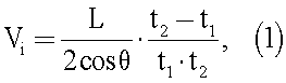
где Vi - это средняя по пути скорость потока (т.е. среднее из скоростей по конкретному ультразвуковому пути) для пути i, L - это длина ультразвукового пути, θ - это угол между ультразвуковым путем и вектором скорости текучей среды, а t1 и t2 - это время прохождения ультразвука в направлении потока и направлении, обратном направлению потока, соответственно.where V i is the average flow velocity along the path (i.e., the average of the velocities along a specific ultrasonic path) for path i, L is the length of the ultrasonic path, θ is the angle between the ultrasonic path and the fluid velocity vector, and t 1 and t 2 is the ultrasound transit time in the flow direction and in the opposite direction to the flow direction, respectively.
Следует отметить, что измеренная средняя по пути скорость Vi отличается от средней по потоку скорости Vavg, при этом последняя является скоростью, усредненной по поперечному сечению потока. Vi измеряется непосредственно ультразвуковым расходомером по времени прохождения с помощью уравнения (1), тогда как Vavg дает скорость потока, которая представляет важность в таких вариантах применения, как передача хранения. Отношение между этими двумя скоростями может быть задано какIt should be noted that the measured average velocity along the path V i differs from the average flow velocity V avg , while the latter is the velocity averaged over the cross section of the flow. V i is measured directly by the ultrasonic flow meter over the travel time using equation (1), while V avg gives the flow rate, which is important in applications such as storage transfer. The ratio between these two speeds can be set as
![]()
![]()
и упоминается как коэффициент канала. В последующем описании Vi упоминается как скорость по пути, а Vavg упоминается как средняя скорость.and is referred to as a channel coefficient. In the following description, V i is referred to as speed along the path, and V avg is referred to as average speed.
Поток в трубопроводе в большинстве случаев протекает в одном из двух режимов: ламинарном режиме и турбулентном режиме. Для этих режимов потока широко известны следующие математические модели:The flow in the pipeline in most cases flows in one of two modes: laminar mode and turbulent mode. The following mathematical models are widely known for these flow modes:

![]()
![]()
Коэффициент степенного закона N является характеристическим значением турбулентного потока. Для полностью развитого турбулентного потока коэффициент степенного закона N может быть оценен с помощью эмпирического уравнения, описанного в литературе (к примеру, L.Lynnworth, "Ultrasonic Measurement for Process Control", Academic Press, San Diego, 1989):The power law coefficient N is the characteristic value of the turbulent flow. For a fully developed turbulent flow, the power law coefficient N can be estimated using the empirical equation described in the literature (for example, L. Lynnworth, "Ultrasonic Measurement for Process Control", Academic Press, San Diego, 1989):
![]()
![]()
где Re - это число Рейнольдса, которое является функцией от скорости потока V и вязкости текучей среды µ:where Re is the Reynolds number, which is a function of the flow rate V and the viscosity of the fluid µ:
![]()
![]()
где D - это диаметр трубы, а ρ - это плотность текучей среды.where D is the diameter of the pipe and ρ is the density of the fluid.
В реальных условиях характеристики трубы и текучей среды зачастую не могут быть точно количественно оценены, и уравнения (5) и (6), в общем, не могут использоваться для получения N в высокоточных измерениях. Следовательно, для данного турбулентного потока необходимо, по меньшей мере, два измерения в двух путях потока для решения уравнения (4) с двумя неизвестными, N и Vc. Именно поэтому многопутевая ультразвуковая технология зачастую необходима для решения вариаций профилей потока.Under real conditions, the characteristics of the pipe and fluid often cannot be accurately quantified, and equations (5) and (6), in general, cannot be used to obtain N in high-precision measurements. Therefore, for a given turbulent flow, at least two measurements in two flow paths are needed to solve equation (4) with two unknowns, N and V c . That is why multi-path ultrasound technology is often needed to solve flow profile variations.
Ссылаясь на фиг.1A, труба 1 показана с тремя парами датчиков, 11a и 11b, 12a и 12b, 13a и 13b. Стрелка 2 показывает направление потока. Линии между парами датчиков показывают ультразвуковые пути. В этой конфигурации ультразвуковой путь между 11a и 11b пересекает осевую линию трубы и упоминается как диагональный путь. Кратчайшее расстояние от пути к осевой линии трубы упоминается как уровень канала. Диагональный путь имеет уровень канала 0. Пути между 12a и 12b и между 13a и 13b имеют одинаковые канальные уровни h даже несмотря на то, что две пары датчиков находятся в различных размещениях. Фиг.1A также иллюстрирует примерный профиль 3 потока.Referring to FIG. 1A,
Коэффициент канала Ki зависит от профилей потока и позиции ультразвукового пути. Для диагонального ультразвукового пути коэффициент канала равен:The channel coefficient K i depends on the flow profiles and the position of the ultrasonic path. For a diagonal ultrasonic path, the channel coefficient is:

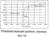
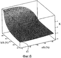
Ссылаясь на фиг.1B, коэффициент канала K (вертикальная ось) показан как функция от числа Рейнольдса Re (горизонтальная ось) в случае диагонального ультразвукового пути. Для недиагональных ультразвуковых путей значения K также могут быть получены аналогичным образом. Отношение между значением K и позициями путей тщательно изучено для профилей ламинарного потока и турбулентного потока еще в Патенте США номер 4078428 от 1978 года. Следовательно, для профилей ламинарного потока и турбулентного потока отношение между измеренными скоростями и фактическими средними скоростями вполне определено.Referring to FIG. 1B, the channel coefficient K (vertical axis) is shown as a function of Reynolds number Re (horizontal axis) in the case of a diagonal ultrasonic path. For off-diagonal ultrasound paths, K values can also be obtained in a similar way. The relationship between K value and path positions has been carefully studied for laminar flow and turbulent flow profiles as early as US Pat. No. 4,078,428 of 1978. Therefore, for the laminar flow and turbulent flow profiles, the relationship between the measured velocities and the actual average velocities is well defined.
Основной задачей ультразвуковых измерителей является быстрое обнаружение профиля потока на основе информации из ограниченного числа путей. Для турбулентного потока случайность измеренных скоростей в выбранных путях может приводить к мгновенному отклонению до 10 процентов от средних значений, а небольшое число путей затрудняет получение достаточной статистической средней скорости потока. В отличие от турбинных измерителей, которые, по сути, выполняют усреднение по всему поперечному сечению потока, ультразвуковые расходомеры по времени прохождения измеряют только ограниченное число выбранных путей скорости потока. Для усреднения случайности измеренных скоростей ультразвуковые измерители должны иметь либо значительное успокоение для необработанных данных, либо большее число путей, распределенных по профилю потока. Использование большого успокоения неблагоприятно влияет на время реакции системы и приводит к недостаточной повторяемости при измерении малых объемов. С другой стороны, добавление большего числа каналов для измерения большего числа путей может значительно увеличить стоимость системы.The main objective of ultrasonic meters is to quickly detect the flow profile based on information from a limited number of paths. For a turbulent flow, the randomness of the measured velocities in the selected paths can lead to an instant deviation of up to 10 percent from the average values, and a small number of paths makes it difficult to obtain a sufficient statistical average flow velocity. Unlike turbine meters, which essentially perform averaging over the entire flow cross section, ultrasonic flow meters measure only a limited number of selected flow velocity paths over their transit time. To average the randomness of the measured velocities, ultrasonic meters should have either significant calm for raw data, or a greater number of paths distributed along the flow profile. The use of large sedation adversely affects the reaction time of the system and leads to insufficient repeatability when measuring small volumes. On the other hand, adding more channels to measure more paths can significantly increase the cost of the system.
Более сложной задачей ультразвуковых расходомеров является обнаружение частично развитых профилей потока. Полностью развитый профиль потока - это, по определению, закон распределения скорости потока, который не меняется в трубе. Все остальные профили потока, которые имеют симметричные распределения скорости вокруг осевой линии трубы, но с развивающимся распределением скорости потока в трубе, в данном описании упоминаются как частично развитые профили потока. Существует две вероятные причины возникновения частично развитых профилей потока. Первая - это переходный профиль между турбулентным и ламинарным потоком, который может возникать в текучих средах с большой вязкостью. Вторая обусловлена наличием устройства задания параметров потока, которое не обладает достаточной длиной в направлении потока, чтобы полностью развить профиль.A more difficult task for ultrasonic flow meters is the detection of partially developed flow profiles. A fully developed flow profile is, by definition, the law of distribution of the flow velocity, which does not change in the pipe. All other flow profiles that have symmetrical velocity distributions around the axial line of the pipe, but with a developing distribution of flow velocity in the pipe, are referred to herein as partially developed flow profiles. There are two likely causes of partially developed flow profiles. The first is the transition profile between the turbulent and laminar flow, which can occur in high viscosity fluids. The second is due to the presence of a device for setting flow parameters, which does not have sufficient length in the direction of flow to fully develop the profile.
Переход между турбулентным потоком и ламинарным потоком обычно происходит, когда число Рейнольдса примерно равно 2300, и это продемонстрировано множеством экспериментов. Тем не менее, как проиллюстрировано на фиг.1B, этот переход может осуществляться в широком диапазоне номеров Рейнольдса и может иметь эффекты запоминания, в зависимости от параметров текучей среды и трубы. Как результат, неправильно использовать число Рейнольдса в качестве единственного индикатора режима профиля потока. Частично развитый профиль рядом с переходной областью может приводить к недопустимо слабой повторяемости при измерениях потока, поскольку ни ламинарная, ни турбулентная модель не является оптимальной для профиля.The transition between the turbulent flow and the laminar flow usually occurs when the Reynolds number is approximately 2300, and this has been demonstrated by many experiments. However, as illustrated in FIG. 1B, this transition can take place over a wide range of Reynolds numbers and can have memory effects, depending on the parameters of the fluid and the pipe. As a result, it is incorrect to use the Reynolds number as the only indicator of the flow profile mode. A partially developed profile near the transition region can lead to unacceptably weak repeatability in flow measurements, since neither the laminar nor turbulent model is optimal for the profile.
Известно, что устойчивому профилю для полного развития требуется определенное прямое и без помех расстояние в трубе. Ссылаясь на фиг.2, пробковый поток 21, который имеет постоянную скорость в поперечном сечении трубы 23, имеющей диаметр D, входит в трубу 23 из гораздо большей трубы 22. Поток изначально имеет частично развитый профиль 24. После входного участка 25 поток имеет полностью развитый профиль 26. И теория, и эксперименты показывают, что входной участок 25 должен иметь длину в 100 раз больше диаметра D трубы для полного развития ламинарного профиля и в 80 раз больше диаметра D трубы для полного развития турбулентного профиля (см. R.W.Fox и A.T.McDonald, "Introduction to Fluid Mechanics", 3rd ed., John Wiley and Sons, New York, 1992). На практике входной поток практически никогда не имеет пробкового профиля, и прямая длина в 10-15 раз больше диаметра D потока, как правило, рекомендуется производителями измерительных приборов для прогнозируемых измерений профилей потока.It is known that a stable profile for full development requires a certain straight and without interference distance in the pipe. Referring to FIG. 2, a
Для многопутевого расходомера при передаче хранения распространено иметь устройство задания параметров потока, установленное в направлении обратного потока расходомера. Основная цель устройства задания параметров потока заключается в снижении завихрений и асимметричного искажения профиля. Более короткое расстояние задания параметров потока всегда является выгодным для производителей и потребителей. Патент США номер 6647806 также предполагает, что более короткое расстояние между устройством задания параметров потока и расходомером позволяет повысить повторяемость измерений.For a multi-path flow meter, it is common for storage transfer to have a flow parameter setting device installed in the return flow direction of the flow meter. The main purpose of the flow parameter setting device is to reduce turbulence and asymmetric distortion of the profile. A shorter distance for setting flow parameters is always beneficial for manufacturers and consumers. U.S. Pat. No. 6,647,806 also contemplates that a shorter distance between the flow parameter setting device and the flowmeter can improve measurement repeatability.
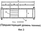
На фиг.3 показано рекомендованное API устройство 31 задания параметров потока, изготовленное из связки небольших труб, имеющих длину B, которое установлено в трубе 32 на расстоянии A от входа в трубу. Расстояние C в направлении потока устройства 31 задания параметров потока рекомендовано иметь в 5 раз превышающим диаметр D трубы 32. Устройство 31 стремится сглаживать профиль потока. В результате наличие устройства 31 либо возмущает ламинарный профиль, либо сглаживает турбулентный профиль. В любом случае в рамках ограниченного входного участка типичный профиль потока (т.е. ламинарный поток или турбулентный поток) может не полностью развиться. В частности, вниз по потоку от устройства задания параметров турбулентный поток может иметь гораздо большее число N, чем оцененное с помощью уравнения (5), и турбулентно-ламинарный переход может возникать при числе Рейнольдса гораздо меньше 2300. В любом случае профиль потока будет непрогнозируемым на основе числа Рейнольдса. Следовательно, по-прежнему требуются усовершенствованные системы и способы мониторинга в реальном времени частично развитых профилей потока.Figure 3 shows the API recommended
Раскрытие изобретенияDisclosure of invention
В одном аспекте раскрытые в данном документе варианты осуществления относятся к способу определения скорости текучей среды, при этом способ содержит этапы, на которых: оценивают число Рейнольдса для текучей среды; сравнивают оцененное число Рейнольдса с выбранным диапазоном; и определяют скорость текучей среды на основе модели потока, выбранной из модели ламинарного потока, модели турбулентного потока и модели частично ламинарного потока.In one aspect, embodiments disclosed herein relate to a method for determining a fluid velocity, the method comprising the steps of: evaluating a Reynolds number for a fluid; comparing the estimated Reynolds number with the selected range; and determining a fluid velocity based on a flow model selected from a laminar flow model, a turbulent flow model, and a partially laminar flow model.
В другом аспекте раскрытые в данном документе варианты осуществления относятся к ультразвуковому расходомеру, содержащему множество пар датчиков, сконфигурированных для формирования множества путей измерения в трубе. Множество путей измерения размещается асимметрично относительно осевой линии трубы.In another aspect, embodiments disclosed herein relate to an ultrasonic flow meter comprising a plurality of pairs of sensors configured to form a plurality of measurement paths in a pipe. Many measurement paths are placed asymmetrically relative to the centerline of the pipe.
Другие аспекты и преимущества изобретения должны стать очевидными из последующего описания и прилагаемой формулы изобретения.Other aspects and advantages of the invention will become apparent from the following description and the appended claims.
Краткое описание чертежейBrief Description of the Drawings
Фиг.1A иллюстрирует конфигурацию многопутевого ультразвукового расходомера по времени прохождения предшествующего уровня техники.1A illustrates the configuration of a multi-path ultrasonic flowmeter over the transit time of the prior art.
Фиг.1B иллюстрирует диаграмму, показывающую значения K для диагонального ультразвукового пути при различных числах Рейнольдса Re.FIG. 1B is a diagram showing K values for a diagonal ultrasonic path at various Reynolds numbers Re.
Фиг.2 иллюстрирует процесс, при котором определенный входной участок необходим для полного развития профиля скорости потока.Figure 2 illustrates the process in which a certain inlet section is necessary for the full development of the flow velocity profile.
Фиг.3 иллюстрирует рекомендованное API устройство задания параметров потока.Figure 3 illustrates a recommended API device for setting flow parameters.
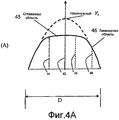
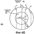
Фиг.4A и 4B иллюстрируют модель частично ламинарного профиля потока в соответствии с одним вариантом осуществления настоящего изобретения.4A and 4B illustrate a model of a partially laminar flow profile in accordance with one embodiment of the present invention.
Фиг.5 иллюстрирует заранее рассчитанную двумерную кривую значений K для турбулентных потоков.5 illustrates a pre-calculated two-dimensional curve of K values for turbulent flows.
Фиг.6 иллюстрирует заранее рассчитанную двумерную кривую значений K для частично ламинарных потоков.6 illustrates a pre-calculated two-dimensional curve of K values for partially laminar flows.
Фиг.7 иллюстрирует набор выведенных одномерных кривых K турбулентных потоков в соответствии с одним вариантом осуществления настоящего изобретения.7 illustrates a set of derived one-dimensional curves K of turbulent flows in accordance with one embodiment of the present invention.
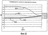
Фиг.8 иллюстрирует набор выведенных одномерных кривых K частично ламинарных потоков в соответствии с одним вариантом осуществления настоящего изобретения.FIG. 8 illustrates a set of derived one-dimensional K partial laminar flow curves in accordance with one embodiment of the present invention.
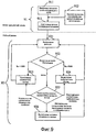
Фиг.9 иллюстрирует блок-схему последовательности операций способа оценки профиля потока в соответствии с одним вариантом осуществления настоящего изобретения.FIG. 9 illustrates a flowchart of a method for estimating a flow profile in accordance with one embodiment of the present invention.
Фиг.10 иллюстрирует примерный набор расходомеров с асимметричным распределением ультразвуковых датчиков.Figure 10 illustrates an exemplary set of flow meters with asymmetric distribution of ultrasonic sensors.
Следует понимать, что чертежи должны использоваться только для иллюстрации, а не в качестве определения границ изобретения или основы для толкования несуществующих или неизложенных ограничений на формулу изобретения.It should be understood that the drawings should be used only for illustration, and not as a definition of the boundaries of the invention or the basis for the interpretation of non-existent or unexplained limitations on the claims.
Осуществление изобретенияThe implementation of the invention
В одном аспекте некоторые раскрытые в данном документе варианты осуществления относятся к способам, которые могут использоваться для измерения скоростей потока даже в случае частично развитых профилей потока, вызываемых либо устройством задания параметров потока, либо ламинарно-турбулентным переходом профиля. Варианты осуществления изобретения могут включать в себя некоторые или все из следующих компонентов: (1) модель частично ламинарного профиля потока, которая разрешает фазу неопределенности в ходе ламинарно-турбулентного перехода; (2) алгоритм поиска и настройки профиля, который подходит к множеству профилей; (3) сочетание ультразвуковых путей, имеющих различные уровни каналов относительно осевой линии трубы.In one aspect, some embodiments disclosed herein relate to methods that can be used to measure flow rates even in the case of partially developed flow profiles caused by either a flow setting device or a laminar-turbulent profile transition. Embodiments of the invention may include some or all of the following components: (1) a model of a partially laminar flow profile that resolves the uncertainty phase during a laminar-turbulent transition; (2) an algorithm for searching and setting up a profile that fits many profiles; (3) a combination of ultrasonic paths having different levels of channels relative to the centerline of the pipe.
В другом аспекте некоторые раскрытые в данном документе варианты осуществления относятся к способам и системам многопутевых ультразвуковых расходомеров, которые позволяют точно измерять частично развитые профили потока. Система в соответствии с одним вариантом осуществления изобретения может включать в себя деталь цилиндрического ультразвукового набора, который имеет два или более ультразвуковых путей, имеющих отличные уровни канала. Некоторые варианты осуществления также могут включать в себя устройство задания параметров потока, которое устраняет большинство завихрений и асимметричных компонентов потока. Способ изобретения может использовать частично ламинарную модель, которая более оптимально представляет профиль потока, частично развитый после устройства задания параметров потока, особенно при небольшом числе Рейнольдса. Способ изобретения также может использовать алгоритм, который выполняет поиск максимального соответствия обнаруженного профиля профилю ламинарного потока, частично ламинарного потока или турбулентного потока.In another aspect, some embodiments disclosed herein relate to methods and systems of multi-path ultrasonic flow meters that accurately measure partially developed flow profiles. A system in accordance with one embodiment of the invention may include a part of a cylindrical ultrasound set that has two or more ultrasonic paths having different channel levels. Some embodiments may also include a flow parameter setting device that eliminates most of the swirls and asymmetric flow components. The method of the invention can use a partially laminar model, which more optimally represents the flow profile, partially developed after the device for setting the flow parameters, especially with a small Reynolds number. The method of the invention can also use an algorithm that searches for the maximum match of the detected profile to the profile of the laminar flow, partially laminar flow or turbulent flow.
Модель частично ламинарного профиля потока в соответствии с одним вариантом осуществления изобретения проиллюстрирована на фиг.4A и 4B. Фиг.4A иллюстрирует поперечный разрез по осевой линии трубы. Труба имеет диаметр D. Пунктирные линии 41-44 представляют намеченные позиции четырех ультразвуковых путей. Профиль скорости потока может быть разделен на две области: ламинарную область 46 и плоскую область 45. Vc - это скорость по осевой линии, если профиль ламинарного потока полностью развился. Сглаживание центрального профиля потока, который отклоняется от ламинарного потока (пунктирная кривая на фиг.4A), может являться результатом ламинарного потока, проходящего через устройство задания параметров потока. Следовательно, набор измеренных скоростей пути в этом случае не соответствует в точности модели чистого ламинарного профиля потока.A partially laminar flow profile model in accordance with one embodiment of the invention is illustrated in FIGS. 4A and 4B. Fig. 4A illustrates a cross section along the axial line of a pipe. The pipe has a diameter D. Dashed lines 41-44 represent the intended positions of the four ultrasonic paths. The flow velocity profile can be divided into two regions: the
В идеале после прохождения достаточного расстояния в направлении потока устройства задания параметров потока ламинарный поток восстанавливается из близости к стенке трубы, и плоская область сокращается и постепенно пропадает. Тем не менее, в реальных ситуациях расстояние между устройством задания параметров потока и расходомером может не быть достаточно большим для полного развития ламинарного профиля, и ультразвуковые лучи должны будут проходить через частично развитый ламинарный профиль аналогично лучам, представленным на фиг.4A.Ideally, after a sufficient distance has been traveled in the flow direction of the device for setting the flow parameters, the laminar flow is restored from proximity to the pipe wall, and the flat region is reduced and gradually disappears. However, in real situations, the distance between the flow parameter setting device and the flowmeter may not be large enough for the laminar profile to fully develop, and ultrasonic rays will have to pass through the partially developed laminar profile similar to the rays shown in Fig. 4A.
Фиг.4B иллюстрирует поперечное сечение в плоскости, перпендикулярной направлению потока. В этой модели частично развитого ламинарного профиля потока плоская область 45 имеет радиус r от осевой линии трубы. Частично ламинарный коэффициент d задается как процент от плоской области в трубе, имеющей радиус R, т.е. d=r/R. Частично ламинарный коэффициент является неизвестным и должен быть найден в ходе измерений потока, когда число Рейнольдса близко к точке перехода.4B illustrates a cross section in a plane perpendicular to the direction of flow. In this model of a partially developed laminar flow profile,
Позиция конкретного пути отличается посредством уровня канала h, который является кратчайшим расстоянием от центральной точки пути к осевой линии трубы. Снова ссылаясь на фиг.4A, уровень канала пути 41 не равен уровню канала пути 43 и уровню канала пути 44, т.е. пути 41, 43 и 44 асимметрично распределены вокруг осевой линии трубы.The position of a particular path is different by the level of the channel h, which is the shortest distance from the center point of the path to the center line of the pipe. Referring again to FIG. 4A, the channel level of the
Аналогично, когда турбулентный поток проходит через устройство задания параметров, участок в направлении потока может не иметь достаточной длины для полного развития турбулентного профиля. Сглаженный профиль по-прежнему является турбулентным профилем, но с более высоким коэффициентом степенного закона N, чем оцененный из числа Рейнольдса. Помимо этого, способ быстрого и широкодиапазонного поиска профиля необходим для решения двух неизвестных: центральной скорости Vc и коэффициента степенного закона N.Similarly, when a turbulent flow passes through a parameter setting device, the portion in the direction of flow may not be of sufficient length for the full development of the turbulent profile. The smoothed profile is still a turbulent profile, but with a higher power law coefficient N than that estimated from the Reynolds number. In addition, a quick and wide-range profile search method is necessary to solve two unknowns: the central velocity V c and the power law coefficient N.
Некоторые варианты осуществления изобретения относятся к алгоритму поиска и настройки профиля. Алгоритм в соответствии с вариантами осуществления изобретения подходит для всех профилей, в том числе и частично развитых профилей. Как упоминалось выше, ламинарные потоки и турбулентные потоки возникают при определенных диапазонах чисел Рейнольдса. Алгоритм в соответствии с вариантами осуществления настоящего изобретения имеет небольшую зависимость от конкретных чисел Рейнольдса. Вместо этого алгоритм имеет три крупных диапазона поиска: чисто ламинарный, переходный и турбулентный. В переходном диапазоне частично ламинарные и турбулентные профили потока экспериментально подобраны, и в качестве модели профиля используется максимальное соответствие. Этот алгоритм требует интенсивных вычислений, особенно когда требуется большое число итераций в интегральных расчетах.Some embodiments of the invention relate to a search and profile tuning algorithm. The algorithm in accordance with embodiments of the invention is suitable for all profiles, including partially developed profiles. As mentioned above, laminar flows and turbulent flows occur at certain ranges of Reynolds numbers. The algorithm in accordance with embodiments of the present invention is slightly dependent on specific Reynolds numbers. Instead, the algorithm has three large search ranges: purely laminar, transitional, and turbulent. In the transition range, partially laminar and turbulent flow profiles are experimentally selected, and the maximum fit is used as the profile model. This algorithm requires intensive calculations, especially when a large number of iterations are required in integral calculations.
Как упоминалось выше, для известного ультразвукового пути и известного профиля потока коэффициент канала K связан со скоростью в пути и средней скоростью. Чтобы вывести среднюю скорость из измеренной скорости в пути, сначала необходимо вывести коэффициент канала K для конкретного пути. В соответствии с некоторыми вариантами осуществления настоящего изобретения может быть использована программа для генерирования базы данных коэффициентов канала K как функций от уровней канала h, коэффициентов степенного закона N и частично ламинарного коэффициента r/R. Затем эта база данных может быть использована в качестве таблицы соответствия для быстрого установления (при известном уровне канала h) отношений между коэффициентом канала K и коэффициентом степенного закона N или частично ламинарным коэффициентом r/R.As mentioned above, for a known ultrasonic path and a known flow profile, the channel coefficient K is related to the speed in the path and the average speed. In order to derive the average speed from the measured speed in the path, it is first necessary to derive the channel coefficient K for a particular path. In accordance with some embodiments of the present invention, a program can be used to generate a database of channel K coefficients as functions of channel levels h, power law coefficients N, and partially laminar coefficient r / R. Then this database can be used as a correspondence table to quickly establish (at a known channel level h) the relationship between the channel coefficient K and the power law coefficient N or partially laminar coefficient r / R.
Ссылаясь на фиг.5, для турбулентного потока или частично развитого турбулентного потока коэффициенты канала K для всех возможных комбинаций уровней канала h (в форме процента от радиуса трубы R) и коэффициенты степенного закона N заранее вычисляются и помещаются в двумерные массивы данных. Аналогично, фиг.6 показывает для частично развитого ламинарного потока двумерные матрицы коэффициентов K как функции от r/R и h/R. Можно видеть, что чистый ламинарный поток является частным случаем частично ламинарного потока, когда радиус плоской области r равен нулю. Например, ссылаясь на фиг.6, когда плоская область не существует (r/R=0) и когда ультразвуковой путь является диагональным (h/R=0), коэффициент K точки 61 данных имеет значение 0,75.Referring to FIG. 5, for a turbulent flow or a partially developed turbulent flow, the channel coefficients K for all possible combinations of channel levels h (in the form of a percentage of the pipe radius R) and the power law coefficients N are pre-computed and put into two-dimensional data arrays. Similarly, FIG. 6 shows, for a partially developed laminar flow, a two-dimensional matrix of coefficients K as a function of r / R and h / R. It can be seen that pure laminar flow is a special case of a partially laminar flow when the radius of the planar region r is zero. For example, referring to FIG. 6, when a planar region does not exist (r / R = 0) and when the ultrasonic path is diagonal (h / R = 0), the coefficient K of the
Двумерные матрицы коэффициентов канала, показанные на фиг.5 и фиг.6, универсально характеризуют измерения потока с помощью ультразвуковых путей. Значения K могут сохраняться как таблицы соответствия в базе данных, являющейся частью вычислительной программы расходомера. В ходе этапа конфигурирования измерителя набор уровней канала h выводится из позиций пар датчиков. Затем программа выполняет поиск кривых функции Ki из таблиц соответствия для каждого ультразвукового пути i.The two-dimensional matrix of channel coefficients shown in FIG. 5 and FIG. 6 universally characterize flow measurements using ultrasonic paths. K values can be stored as correspondence tables in a database that is part of the flowmeter’s computing program. During the configuration of the meter, the set of channel levels h is derived from the positions of the pairs of sensors. Then the program searches for curves of the function K i from the correspondence tables for each ultrasonic path i.
В целях иллюстрации на фиг.7 и фиг.8 показано два набора одномерных матриц, дискретизированных из двумерных матриц с известными уровнями канала. Фиг.7 иллюстрирует коэффициенты K турбулентного потока как функции от N. Четыре кривые 721-724 соответствуют четырем различным каналам 1-4 и получаются посредством нахождения двумерных матриц на фиг.5 для четырех конкретных значений h/R. Например, кривая 722 - это коэффициенты K для канала с диагональным путем, и она выводится из фиг.5 посредством задания h/R=0.For purposes of illustration, FIGS. 7 and 8 show two sets of one-dimensional matrices discretized from two-dimensional matrices with known channel levels. FIG. 7 illustrates turbulent flow coefficients K as a function of N. Four curves 721–724 correspond to four
Фиг.8 иллюстрирует коэффициенты K как функции от d для частично развитого ламинарного потока. Четыре кривые 821-824 соответствуют четырем различным путям каналов 1-4 и получаются посредством поиска на фиг.6 кривых, имеющих конкретные уровни канала h. Когда d=0, т.е. когда поток является чистым ламинарным, значение K, измеренное в диагональном пути 822, равно 0,75. С другой стороны, когда d=1, т.е. когда поток является пробковым потоком, все значения K сходятся к значению 1.Fig. 8 illustrates K coefficients as a function of d for a partially developed laminar flow. Four curves 821-824 correspond to four different paths of channels 1-4 and are obtained by searching in FIG. 6 for curves having specific levels of channel h. When d = 0, i.e. when the flow is pure laminar, the K value measured in
В типичной прямой трубе переходный поток возникает, когда число Рейнольдса примерно равно 2300. Это значение может изменяться в зависимости от параметров трубы, а также предыстории потока. Наличие устройства задания параметров потока делает режимы профиля потока еще более непредсказуемыми. Результаты экспериментов показали, что ламинарный поток может полностью развиться после прохождения через устройство задания параметров потока и до достижения набора измерителей, если число Рейнольдса меньше 1000. С другой стороны, маловероятно, чтобы поток мог восстанавливать ламинарный профиль при числе Рейнольдса больше 5000, когда присутствует устройство задания параметров потока. На основе этих результатов, в соответствии с одним вариантом осуществления изобретения, когда число Рейнольдса находится между нижним пределом, к примеру 1000, и верхним пределом, к примеру 5000, частично ламинарная модель используется для подбора профиля потока. Значения нижнего предела 1000 и верхнего предела 5000 используются в данном описании для иллюстрации. Специалисты в данной области техники должны принимать во внимание, что другие пределы также могут использоваться без отступления от области применения изобретения. Например, более широкий диапазон чисел Рейнольдса, к примеру от 500 до 10000, может использоваться для поиска возможных переходных профилей, если точная вязкость текучей среды недоступна при проведении измерений.In a typical straight pipe, a transient flow occurs when the Reynolds number is approximately 2300. This value may vary depending on the parameters of the pipe, as well as the history of the flow. The presence of a flow parameter setting device makes the flow profile modes even more unpredictable. The experimental results showed that the laminar flow can fully develop after passing through the device to set the flow parameters and until a set of meters is reached if the Reynolds number is less than 1000. On the other hand, it is unlikely that the flow could restore the laminar profile with a Reynolds number greater than 5000 when the device is present setting flow parameters. Based on these results, in accordance with one embodiment of the invention, when the Reynolds number is between a lower limit, for example 1000, and an upper limit, for example 5000, a partially laminar model is used to select a flow profile. The values of the
В ходе измерений потока, в соответствии с одним вариантом осуществления изобретения, выполняется начальная оценка средней скорости потока, а следовательно, и оценка числа Рейнольдса. Если число Рейнольдса Re>5000, вероятно, поток является турбулентным. В таком случае программа вычисляет приблизительное значение N с помощью уравнения (5) на основе оцененного числа Рейнольдса Re. В диапазоне оцененного N далее программа выполняет поиск четырех кривых на фиг.7 для N, которое дает оптимальный набор коэффициентов K, т.е. четырех выведенных значений Vavg=Vi*Ki, на основе четырех измеренных значений Vi' и четырех значений Ki', полученных из фиг.7 с помощью значения N, имеющего наименьшую статистическую дисперсию. Это новое выведенное значение N является более точным, чем вычисленное с помощью уравнения (5). Найденное значение N может быть передано обратно в программу для итераций, чтобы получить еще большую точность. Аппроксимация кривой может основываться на максимальном соответствии с наименьшим статистическим отклонением. Специалисты в данной области техники должны признавать, что множество способов аппроксимации кривой может использоваться без отступления от области применения настоящего изобретения. Кроме того, число путей может превышать 4 или быть меньше 4.In the course of flow measurements, in accordance with one embodiment of the invention, an initial estimate of the average flow rate, and therefore an estimate of the Reynolds number, is performed. If the Reynolds number Re> 5000, it is likely that the flow is turbulent. In this case, the program calculates the approximate value of N using equation (5) based on the estimated Reynolds number Re. In the range of estimated N, the program then searches for four curves in Fig. 7 for N, which gives an optimal set of K coefficients, i.e. the four derived values of V avg = V i * K i , based on the four measured values of V i 'and the four values of K i ' obtained from Fig. 7 using the N value having the smallest statistical variance. This newly derived value of N is more accurate than that calculated using equation (5). The found value of N can be transferred back to the program for iterations in order to obtain even greater accuracy. The approximation of the curve can be based on the maximum fit with the smallest statistical deviation. Those skilled in the art will recognize that a variety of curve fitting methods can be used without departing from the scope of the present invention. In addition, the number of paths may exceed 4 or be less than 4.
С другой стороны, если Re<1000, то программа подгоняет измеренные данные к ламинарному профилю с помощью соответствующих уравнений. Если Re между 1000 и 5000 и невозможно достоверно установить, является поток ламинарным, частично ламинарным или турбулентным, программа пытается подобрать измеренные данные с помощью трех различных профилей и находит максимальное соответствие, которое, в свою очередь, определяет истинный профиль потока. Например, если частично ламинарная модель максимально соответствует данным, то программа определяет значение d из фиг.8. От осевой линии трубы до расстояния r=dR поток является "сглаженным". Специалисты в данной области техники должны признавать, что хотя профиль потока в плоской области моделируется с помощью профиля с постоянной скоростью, более сложные модели могут использоваться для моделирования профиля потока в плоской области, которая отличается от ламинарного профиля потока.On the other hand, if Re <1000, then the program adjusts the measured data to the laminar profile using the appropriate equations. If Re between 1000 and 5000 and it is impossible to reliably establish whether the flow is laminar, partially laminar or turbulent, the program tries to select the measured data using three different profiles and finds the maximum match, which, in turn, determines the true flow profile. For example, if the partially laminar model matches the data as much as possible, then the program determines the value of d from Fig. 8. From the centerline of the pipe to a distance r = dR, the flow is “smoothed”. Those of skill in the art should recognize that although a flow profile in a planar region is modeled using a constant velocity profile, more sophisticated models can be used to model a flow profile in a planar region that is different from the laminar flow profile.
В ходе работы расходомера, поскольку доступ к таблицам соответствия выполняется гораздо быстрее, чем выполнение интегральных расчетов в реальном времени, время обработки данных должно существенно снижаться, и расходомер может быть сконфигурирован на месте под различные структуры путей. Тем не менее, специалисты в данной области техники должны принимать во внимание, что варианты осуществления изобретения могут использовать либо заранее вычисленные таблицы соответствия, либо программу расчетов в реальном времени.During the operation of the flowmeter, since access to the correspondence tables is much faster than performing integral calculations in real time, the data processing time should be significantly reduced, and the flowmeter can be configured in place for various path structures. However, those skilled in the art will appreciate that embodiments of the invention may use either pre-computed match tables or a real-time calculation program.
Способ в соответствии с одним вариантом осуществления изобретения проиллюстрирован на фиг.9. Алгоритм включает в себя два режима: конфигурационный режим 91 и рабочий режим 92. В конфигурационном режиме 91 на этапе 911 пользователь определяет уникальную комбинацию путей и вводит эту информацию в вычислительную программу. С помощью двумерных матриц коэффициентов канала, заранее вычисленных на этапе 912, вычислительная программа выводит на этапе 913 кривые коэффициентов канала для конкретной конфигурации пути, как описано выше со ссылкой на фиг.7 и фиг.8.The method in accordance with one embodiment of the invention is illustrated in Fig.9. The algorithm includes two modes:
В рабочем режиме 92 компонент 921 вычисления профиля потока сначала вычисляет число Рейнольдса с помощью уравнения (6) и сравнивает на этапе 922 число Рейнольдса с заранее определенным диапазоном. Если число Рейнольдса меньше нижнего предела заранее определенного диапазона, причем в данном примерном случае нижний диапазон равен 1000, программа выполняет вычисление ламинарного потока на этапе 923. Если число Рейнольдса больше верхнего предела заранее определенного диапазона, причем в данном примерном случае верхний диапазон равен 5000, программа выполняет вычисление турбулентного потока на этапе 924. Если число Рейнольдса попадает в заранее определенный диапазон, в данном примерном случае находящийся между 1000 и 5000, программа ищет максимальное соответствие (этап 925) из ламинарных профилей, турбулентных профилей и частично ламинарных профилей и затем выполняет этапы 923, 924 или 926, соответственно. Вышеприведенные этапы могут итеративно выполняться до тех пор, пока не будет получена требуемая точность результатов.In operating
Способы изобретения, проиллюстрированные выше, могут быть осуществлены в одной или более вычислительных программах, подходящих для эксплуатационной конфигурации, для широкого диапазона многопутевых структур и установок устройства задания параметров потока.The methods of the invention illustrated above can be implemented in one or more computing programs suitable for an operational configuration for a wide range of multipath structures and settings of a flow parameter setting device.
Некоторые варианты осуществления изобретения относятся к многопутевому ультразвуковому расходомеру. На фиг.10 проиллюстрирована примерная деталь многопутевого ультразвукового набора с асимметричной структурой размещения путей. В этом варианте осуществления 4-путевой набор измерителей показан в поперечном сечении. Четыре пары ультразвуковых датчиков, 101a и 101b, 102a и 102b, 103a и 103b, 104a и 104b, крепятся к стенке 105 трубы, при этом каждая пара измеряет скорость потока конкретного пути, такого как пути 41-44 на фиг.4A. Пары датчиков подключены к блоку 106 управления, который может включать схему 107 управления вводом-выводом, электронную цифровую вычислительную машину или центральный процессор (ЦП) 108 и машиночитаемый носитель 109. Машиночитаемый носитель (к примеру, запоминающее устройство) 109 может хранить программу, содержащую инструкции для исполнения способа в соответствии с вариантами осуществления изобретения. В некоторых вариантах осуществления машиночитаемый носитель 109 также может хранить базу данных, включающую в себя заранее вычисленные результаты в форме таблиц соответствия. Специалисты в данной области техники должны признавать, что существует множество возможных вариантов осуществления для блока 106 управления, и программы или базы данных могут храниться или переноситься с помощью различных типов машиночитаемых носителей, в том числе, но не только, ПЗУ, ОЗУ, жестких дисков, гибких дисков, компакт-дисков и флэш-дисков.Some embodiments of the invention relate to a multi-path ultrasonic flowmeter. 10 illustrates an exemplary detail of a multi-path ultrasound set with an asymmetric path arrangement. In this embodiment, a 4-way gauge set is shown in cross section. Four pairs of ultrasonic sensors, 101a and 101b, 102a and 102b, 103a and 103b, 104a and 104b, are attached to the pipe wall 105, with each pair measuring the flow rate of a particular path, such as paths 41-44 in FIG. 4A. The pairs of sensors are connected to a control unit 106, which may include an input / output control circuit 107, an electronic digital computer or central processing unit (CPU) 108, and a computer-readable medium 109. A computer-readable medium (for example, a storage device) 109 may store a program containing instructions to execute a method in accordance with embodiments of the invention. In some embodiments, the computer-readable medium 109 may also store a database including pre-computed results in the form of correspondence tables. Specialists in the art should recognize that there are many possible embodiments for the control unit 106, and programs or databases can be stored or transferred using various types of computer-readable media, including but not limited to ROM, RAM, hard drives, floppy disks, CDs and flash drives.
Как упоминалось выше, по меньшей мере, два пути, каждый из которых имеет различное расстояние от осевой линии трубы, необходимы для нахождения общего профиля потока. Тем не менее, на практике зачастую требуется больше двух путей для усреднения случайности измерений и повышения разрешения профилей, скрытых в случайных процессах. С другой стороны, число ультразвуковых путей всегда ограничено требованиями по размерам и цене.As mentioned above, at least two paths, each of which has a different distance from the axial line of the pipe, are necessary to find a common flow profile. However, in practice, more than two ways are often required to average the randomness of measurements and increase the resolution of profiles hidden in random processes. On the other hand, the number of ultrasonic paths is always limited by size and price requirements.
Следует отметить, что в соответствии с предпочтительным вариантом осуществления настоящего изобретения несколько путей имеют асимметричное распределение вокруг осевой линии трубы. Каждый из этих путей имеет свой отличный уровень канала от осевой линии трубы и предоставляет уникальную информацию о профиле потока. В отличие от этого, набор измерителей с одинаковым числом путей, но использующих симметричное распределение путей, предоставляет меньше информации.It should be noted that in accordance with a preferred embodiment of the present invention, several paths have an asymmetric distribution around the axial line of the pipe. Each of these paths has its own excellent channel level from the centerline of the pipe and provides unique information about the flow profile. In contrast, a set of meters with the same number of paths but using a symmetrical path distribution provides less information.
Преимущества настоящего изобретения включают в себя одно или более из следующего: (a) точные и быстрые измерения потока, охватывающие широкий диапазон профилей потока, в том числе ламинарный поток, турбулентный поток и частично ламинарный поток; (b) меньшая зависимость от выбора устройства задания параметров и короче стандартного расстояние между устройством задания параметров и областью ультразвуковых измерений может быть достаточным, что обеспечивает потребителям выгоду при установке и по стоимости; (c) более быстрая реакция как ответ заранее вычисленных таблиц соответствия; (d) меньше число ультразвуковых путей и датчиков требуется в результате асимметричной конфигурации путей.Advantages of the present invention include one or more of the following: (a) accurate and fast flow measurements covering a wide range of flow profiles, including laminar flow, turbulent flow, and partially laminar flow; (b) a smaller dependence on the choice of the parameter setting device and shorter than the standard distance between the parameter setting device and the ultrasonic measurement area can be sufficient, which provides consumers with benefits in installation and cost; (c) faster response as a response to pre-computed match tables; (d) fewer ultrasound paths and sensors are required as a result of asymmetric path configuration.
Хотя изобретение описано относительно ограниченного числа вариантов осуществления, специалисты в данной области техники, воспользовавшись выгодами данной сущности, должны признавать, что могут быть другие варианты осуществления без отступления от области применения изобретения, раскрываемой в данном документе. Следовательно, область применения изобретения ограничена только прилагаемой формулой изобретения.Although the invention has been described with respect to a limited number of embodiments, those skilled in the art, taking advantage of the gist, should recognize that there may be other embodiments without departing from the scope of the invention disclosed herein. Therefore, the scope of the invention is limited only by the attached claims.
Claims (17)
оценивают число Рейнольдса для текучей среды при помощи ультразвукового расходомера, имеющего множество пар датчиков, сконфигурированных для формирования множества путей измерения в трубе, при этом множество путей измерения размещается асимметрично относительно осевой линии трубы;
сравнивают оцененное число Рейнольдса с выбранным диапазоном; и
определяют скорость текучей среды на основе модели потока, выбранной из модели ламинарного потока, модели турбулентного потока и модели частично ламинарного потока, причем упомянутую модель выбирают, основываясь на результатах сравнения оцененного числа Рейнольдса упомянутой текучей среды и выбранного диапазона чисел Рейнольдса.1. A method for determining the velocity of a fluid, the method comprising the steps of
estimating the Reynolds number for the fluid using an ultrasonic flow meter having a plurality of pairs of sensors configured to form a plurality of measurement paths in the pipe, wherein the plurality of measurement paths are placed asymmetrically with respect to the axial line of the pipe;
comparing the estimated Reynolds number with the selected range; and
determining a fluid velocity based on a flow model selected from a laminar flow model, a turbulent flow model, and a partially laminar flow model, said model being selected based on a comparison of the estimated Reynolds number of said fluid and a selected range of Reynolds numbers.
оценивают число Рейнольдса для текучей среды при помощи ультразвукового расходомера, имеющего множество пар датчиков, сконфигурированных для формирования множества путей измерения в трубе, при этом множество путей измерения размещается асимметрично относительно осевой линии трубы;
сравнивают оцененное число Рейнольдса с выбранным диапазоном; и
определяют скорость текучей среды на основе модели потока, выбранной из модели ламинарного потока, модели турбулентного потока и модели частично ламинарного потока, причем упомянутую модель выбирают, основываясь на результатах сравнения оцененного числа Рейнольдса упомянутой текучей среды и выбранного диапазона чисел Рейнольдса.10. A computer-readable medium storing a program containing instructions that, when executed by a computer, causes the computer to implement the steps of the method for determining a fluid flow rate based on a flow model, on which
estimating the Reynolds number for the fluid using an ultrasonic flow meter having a plurality of pairs of sensors configured to form a plurality of measurement paths in the pipe, wherein the plurality of measurement paths are placed asymmetrically with respect to the axial line of the pipe;
comparing the estimated Reynolds number with the selected range; and
determining a fluid velocity based on a flow model selected from a laminar flow model, a turbulent flow model, and a partially laminar flow model, said model being selected based on a comparison of the estimated Reynolds number of said fluid and a selected range of Reynolds numbers.
множество пар датчиков, сконфигурированных для формирования множества путей измерения в трубе, при этом множество путей измерения размещается асимметрично относительно осевой линии трубы; и
блок управления, причем упомянутое множество пар датчиков соединено с блоком управления, причем блок управления содержит
процессор и запоминающее устройство, причем запоминающее устройство хранит программу, имеющую инструкции для
определения скорости потока текучей среды на основе модели потока, выбранной из модели ламинарного потока, модели турбулентного потока и модели частично ламинарного потока, при этом модель потока выбирается на основе сравнения оцененного числа Рейнольдса текучей среды с выбранным диапазоном чисел Рейнольдса.15. An ultrasonic flow meter, wherein the ultrasonic flow meter comprises
a plurality of pairs of sensors configured to form a plurality of measurement paths in the pipe, wherein the plurality of measurement paths are placed asymmetrically with respect to the axial line of the pipe; and
a control unit, wherein said plurality of pairs of sensors are connected to the control unit, the control unit comprising
a processor and a storage device, the storage device storing a program having instructions for
determining a fluid flow rate based on a flow model selected from a laminar flow model, a turbulent flow model, and a partially laminar flow model, the flow model being selected based on a comparison of the estimated Reynolds number of the fluid with a selected range of Reynolds numbers.
Applications Claiming Priority (2)
| Application Number | Priority Date | Filing Date | Title |
|---|---|---|---|
| US11/300,128 US7299140B2 (en) | 2005-12-14 | 2005-12-14 | Method and system for multi-path ultrasonic flow measurement of partially developed flow profiles |
| US11/300,128 | 2005-12-14 |
Publications (2)
| Publication Number | Publication Date |
|---|---|
| RU2006144584A RU2006144584A (en) | 2008-06-20 |
| RU2392588C2 true RU2392588C2 (en) | 2010-06-20 |
Family
ID=37912439
Family Applications (1)
| Application Number | Title | Priority Date | Filing Date |
|---|---|---|---|
| RU2006144584/28A RU2392588C2 (en) | 2005-12-14 | 2006-12-13 | Method and system for multipath ultrasonic measurement of flow parametres and partly developed flow profiles |
Country Status (6)
| Country | Link |
|---|---|
| US (1) | US7299140B2 (en) |
| EP (1) | EP1798530A3 (en) |
| JP (1) | JP4668163B2 (en) |
| CN (1) | CN1982895B (en) |
| CA (1) | CA2570456C (en) |
| RU (1) | RU2392588C2 (en) |
Cited By (2)
| Publication number | Priority date | Publication date | Assignee | Title |
|---|---|---|---|---|
| RU2580898C1 (en) * | 2013-04-25 | 2016-04-10 | Вуджин Инк. | Ultrasonic system of flow measurement |
| RU2772552C2 (en) * | 2018-10-01 | 2022-05-23 | ДЭНИЕЛ МЕЖЕМЕНТ энд КОНТРОЛ, ИНК. | Ultrasonic transducer with sealed 3d-printed miniature horn array |
Families Citing this family (20)
| Publication number | Priority date | Publication date | Assignee | Title |
|---|---|---|---|---|
| US7729869B2 (en) * | 2007-11-16 | 2010-06-01 | Burger & Brown Engineering, Inc. | Electronic flow characteristic indicating flow meter |
| MX2010011216A (en) * | 2008-04-22 | 2010-11-12 | Cameron Int Corp | Smooth bore, chordal transit-time ultrasonic meter and method. |
| US7942068B2 (en) * | 2009-03-11 | 2011-05-17 | Ge Infrastructure Sensing, Inc. | Method and system for multi-path ultrasonic flow rate measurement |
| US9320496B2 (en) * | 2010-02-25 | 2016-04-26 | Siemens Medical Solutions Usa, Inc. | Volumetric is quantification for ultrasound diagnostic imaging |
| US8429985B2 (en) | 2010-08-24 | 2013-04-30 | General Electric Company | Apparatus for use in determining a plurality of characteristics of a multiphase flow within a pipe |
| CN102087130B (en) * | 2010-11-19 | 2012-02-15 | 北京工业大学 | Computational fluid dynamics (CFD) technology-based method for optimizing acoustic path of multi-path ultrasonic flowmeter assembled in elbow pipe |
| FR2970083B1 (en) * | 2011-01-05 | 2013-02-15 | Leosphere | METHOD AND DEVICE FOR DETERMINING THE MOVEMENTS OF A FLUID FROM DISTANCE MEASUREMENTS OF RADIAL SPEEDS. |
| DE102011080365A1 (en) * | 2011-08-03 | 2013-02-07 | Endress + Hauser Flowtec Ag | Method for determining the flow by means of ultrasound |
| US9068870B2 (en) | 2013-02-27 | 2015-06-30 | Daniel Measurement And Control, Inc. | Ultrasonic flow metering with laminar to turbulent transition flow control |
| US9135379B2 (en) | 2013-03-15 | 2015-09-15 | Sas Ip, Inc. | Systems and methods for multi-zonal analysis of physical objects |
| DE102014004747B4 (en) * | 2013-10-30 | 2023-02-16 | Krohne Ag | Ultrasonic flow meter |
| US9255827B2 (en) * | 2013-12-17 | 2016-02-09 | International Business Machines Corporation | Computer based fluid flow velocity estimation from concentrations of a reacting constituent for products and services |
| US11047722B2 (en) | 2013-12-17 | 2021-06-29 | International Business Machines Corporation | Computer based fluid flow velocity estimation from concentrations of a reacting constituent for products and services |
| US9304024B2 (en) | 2014-01-13 | 2016-04-05 | Cameron International Corporation | Acoustic flow measurement device including a plurality of chordal planes each having a plurality of axial velocity measurements using transducer pairs |
| CN103808381B (en) * | 2014-03-04 | 2016-06-15 | 华南理工大学 | A kind of temperature influence eliminating method of transit-time ultrasonic flow meter |
| CN104090020A (en) * | 2014-07-10 | 2014-10-08 | 天津大学 | Electric and ultrasonic-based bimodal multiphase flow measuring device |
| CN105737918B (en) * | 2014-12-11 | 2019-05-10 | 通用电气公司 | For measuring the ultrasonic method and device of fluid flow |
| CN108491561B (en) * | 2018-01-26 | 2021-05-11 | 中国水利水电科学研究院 | Radial gate over-flow calculation method based on flow state identification |
| CN112149238B (en) * | 2019-06-10 | 2022-10-04 | 中国石油天然气股份有限公司 | Method and device for determining floating speed of bubbles in gas-liquid separator |
| WO2021081385A1 (en) * | 2019-10-25 | 2021-04-29 | Klein Marine Systems, Inc. | Variable geometry sonar system and method |
Family Cites Families (12)
| Publication number | Priority date | Publication date | Assignee | Title |
|---|---|---|---|---|
| US4078428A (en) * | 1974-11-21 | 1978-03-14 | National Research Development Corporation | Measurement of fluid flow |
| US4517847A (en) * | 1982-10-27 | 1985-05-21 | The Foxboro Company | Flowmeter having uniform response under both laminar and turbulent flow conditions |
| US4856321A (en) * | 1983-07-29 | 1989-08-15 | Panametrics, Inc. | Apparatus and methods for measuring fluid flow parameters |
| JP3194270B2 (en) * | 1995-02-28 | 2001-07-30 | 経済産業省産業技術総合研究所長 | Ultrasonic flow meter |
| NL1001719C2 (en) * | 1995-11-22 | 1997-05-23 | Krohne Altometer | Method and device for the ultrasonic measurement of the velocity and flow rate of a medium in a pipeline. |
| US5835884A (en) * | 1996-10-04 | 1998-11-10 | Brown; Alvin E. | Method of determining a characteristic of a fluid |
| US6047602A (en) * | 1996-10-29 | 2000-04-11 | Panametrics, Inc. | Ultrasonic buffer/waveguide |
| US6067861A (en) * | 1998-06-18 | 2000-05-30 | Battelle Memorial Institute | Method and apparatus for ultrasonic doppler velocimetry using speed of sound and reflection mode pulsed wideband doppler |
| US6378357B1 (en) * | 2000-03-14 | 2002-04-30 | Halliburton Energy Services, Inc. | Method of fluid rheology characterization and apparatus therefor |
| US6647806B1 (en) * | 2000-07-14 | 2003-11-18 | Caldon, Inc. | Turbulence conditioner for use with transit time ultrasonic flowmeters |
| JP2002039824A (en) * | 2000-07-25 | 2002-02-06 | Yazaki Corp | Flow rate measurement device |
| KR100374429B1 (en) * | 2000-09-15 | 2003-03-04 | 인터내셔날하이드로손닉 주식회사 | Multi-path Ultrasonic Flow rate Measuring Method |
-
2005
- 2005-12-14 US US11/300,128 patent/US7299140B2/en active Active
-
2006
- 2006-12-05 EP EP06125459A patent/EP1798530A3/en not_active Withdrawn
- 2006-12-05 JP JP2006328590A patent/JP4668163B2/en not_active Expired - Fee Related
- 2006-12-06 CA CA2570456A patent/CA2570456C/en not_active Expired - Fee Related
- 2006-12-13 RU RU2006144584/28A patent/RU2392588C2/en not_active IP Right Cessation
- 2006-12-13 CN CN2006101669564A patent/CN1982895B/en not_active Expired - Fee Related
Cited By (2)
| Publication number | Priority date | Publication date | Assignee | Title |
|---|---|---|---|---|
| RU2580898C1 (en) * | 2013-04-25 | 2016-04-10 | Вуджин Инк. | Ultrasonic system of flow measurement |
| RU2772552C2 (en) * | 2018-10-01 | 2022-05-23 | ДЭНИЕЛ МЕЖЕМЕНТ энд КОНТРОЛ, ИНК. | Ultrasonic transducer with sealed 3d-printed miniature horn array |
Also Published As
| Publication number | Publication date |
|---|---|
| US20070136008A1 (en) | 2007-06-14 |
| CA2570456A1 (en) | 2007-06-14 |
| CA2570456C (en) | 2012-04-17 |
| JP2007163478A (en) | 2007-06-28 |
| US7299140B2 (en) | 2007-11-20 |
| JP4668163B2 (en) | 2011-04-13 |
| CN1982895A (en) | 2007-06-20 |
| EP1798530A3 (en) | 2007-07-25 |
| EP1798530A2 (en) | 2007-06-20 |
| CN1982895B (en) | 2010-12-15 |
| RU2006144584A (en) | 2008-06-20 |
Similar Documents
| Publication | Publication Date | Title |
|---|---|---|
| RU2392588C2 (en) | Method and system for multipath ultrasonic measurement of flow parametres and partly developed flow profiles | |
| US9310237B2 (en) | Ultrasonic flow metering using compensated computed temperature | |
| US7654151B2 (en) | Method and apparatus for measuring multi-streams and multi-phase flow | |
| CA2702666C (en) | A method and system for detecting deposit buildup within an ultrasonic flow meter | |
| US9134155B2 (en) | Reynolds number based verification for ultrasonic flow metering systems | |
| CN204115825U (en) | There is the ultrasonic flow rate metering system of upstream pressure transducer | |
| US10928230B2 (en) | Acoustic flow measurement device including a plurality of chordal planes each having a plurality of axial velocity measurements using transducer pairs | |
| WO2013006090A1 (en) | The calibration method, applied in operating conditions, for ultrasonic flow meters used for measuring volume and flow rate of single-phase liquid media | |
| US7643947B2 (en) | System and method for flow profile calibration correction for ultrasonic flowmeters | |
| US20230086744A1 (en) | Ultrasonic meter employing two or more dissimilar chordal multipath integration methods in one body | |
| Drenthen et al. | The manufacturing of ultrasonic gas flow meters | |
| WO2005040732A1 (en) | Wet gas measurement apparatus and method | |
| KR102507267B1 (en) | A method of measuring the near-wall velocity of pipelines and Recording medium on which the same algorithm is recorded | |
| dos Reis et al. | On the measurement of the mass flow rate of horizontal two-phase flows in the proximity of the transition lines which separates two different flow patterns | |
| Nouri et al. | Numerical analysis of liquid flow measurement using multipath ultrasonic phased array flowmeter | |
| EP3729017A1 (en) | Multi-fluid calibration | |
| CN105890684A (en) | Novel setting method for determining sound channel positions by adopting Gauss-Jacobi polynomial | |
| CN116878624A (en) | Measuring method and device of multichannel ultrasonic gas flowmeter and electronic equipment | |
| JP2022159920A (en) | Estimation device of internal state of pipeline, and estimation method of internal state of pipeline | |
| Matiko et al. | Reduction of Hydrodynamic Flow Measurement Error of Chordal Ultrasonic Flowmeter | |
| Kalivoda et al. | Dynamic Testing | |
| JP2023010241A (en) | Abnormality detection device and abnormality detection method | |
| Kabaciński | Experimental research on velocity profiles in selected flow systems | |
| Razaghi | Methodology and case study of commercially optimum prover sizing for an ultrasonic fiscal metering system of crude oil | |
| Golijanek-Jędrzejczyk | Characteristics of the Flow Coefficient C for Centric, Segmental and Multi-Hole Orifices |
Legal Events
| Date | Code | Title | Description |
|---|---|---|---|
| MM4A | The patent is invalid due to non-payment of fees |
Effective date: 20201214 |