RU2384292C1 - Blood pressure measuring device enabling high-precision measurement of blood pressure - Google Patents
Blood pressure measuring device enabling high-precision measurement of blood pressure Download PDFInfo
- Publication number
- RU2384292C1 RU2384292C1 RU2008126205/14A RU2008126205A RU2384292C1 RU 2384292 C1 RU2384292 C1 RU 2384292C1 RU 2008126205/14 A RU2008126205/14 A RU 2008126205/14A RU 2008126205 A RU2008126205 A RU 2008126205A RU 2384292 C1 RU2384292 C1 RU 2384292C1
- Authority
- RU
- Russia
- Prior art keywords
- compressing
- measuring
- chamber
- pneumatic
- compression
- Prior art date
Links
Images


Classifications
-
- A—HUMAN NECESSITIES
- A61—MEDICAL OR VETERINARY SCIENCE; HYGIENE
- A61B—DIAGNOSIS; SURGERY; IDENTIFICATION
- A61B5/00—Measuring for diagnostic purposes; Identification of persons
- A61B5/02—Detecting, measuring or recording pulse, heart rate, blood pressure or blood flow; Combined pulse/heart-rate/blood pressure determination; Evaluating a cardiovascular condition not otherwise provided for, e.g. using combinations of techniques provided for in this group with electrocardiography or electroauscultation; Heart catheters for measuring blood pressure
- A61B5/021—Measuring pressure in heart or blood vessels
- A61B5/022—Measuring pressure in heart or blood vessels by applying pressure to close blood vessels, e.g. against the skin; Ophthalmodynamometers
- A61B5/02233—Occluders specially adapted therefor
-
- A—HUMAN NECESSITIES
- A61—MEDICAL OR VETERINARY SCIENCE; HYGIENE
- A61B—DIAGNOSIS; SURGERY; IDENTIFICATION
- A61B5/00—Measuring for diagnostic purposes; Identification of persons
- A61B5/02—Detecting, measuring or recording pulse, heart rate, blood pressure or blood flow; Combined pulse/heart-rate/blood pressure determination; Evaluating a cardiovascular condition not otherwise provided for, e.g. using combinations of techniques provided for in this group with electrocardiography or electroauscultation; Heart catheters for measuring blood pressure
- A61B5/021—Measuring pressure in heart or blood vessels
- A61B5/022—Measuring pressure in heart or blood vessels by applying pressure to close blood vessels, e.g. against the skin; Ophthalmodynamometers
-
- A—HUMAN NECESSITIES
- A61—MEDICAL OR VETERINARY SCIENCE; HYGIENE
- A61B—DIAGNOSIS; SURGERY; IDENTIFICATION
- A61B5/00—Measuring for diagnostic purposes; Identification of persons
- A61B5/02—Detecting, measuring or recording pulse, heart rate, blood pressure or blood flow; Combined pulse/heart-rate/blood pressure determination; Evaluating a cardiovascular condition not otherwise provided for, e.g. using combinations of techniques provided for in this group with electrocardiography or electroauscultation; Heart catheters for measuring blood pressure
- A61B5/021—Measuring pressure in heart or blood vessels
- A61B5/02141—Details of apparatus construction, e.g. pump units or housings therefor, cuff pressurising systems, arrangements of fluid conduits or circuits
-
- A—HUMAN NECESSITIES
- A61—MEDICAL OR VETERINARY SCIENCE; HYGIENE
- A61B—DIAGNOSIS; SURGERY; IDENTIFICATION
- A61B5/00—Measuring for diagnostic purposes; Identification of persons
- A61B5/02—Detecting, measuring or recording pulse, heart rate, blood pressure or blood flow; Combined pulse/heart-rate/blood pressure determination; Evaluating a cardiovascular condition not otherwise provided for, e.g. using combinations of techniques provided for in this group with electrocardiography or electroauscultation; Heart catheters for measuring blood pressure
- A61B5/021—Measuring pressure in heart or blood vessels
- A61B5/022—Measuring pressure in heart or blood vessels by applying pressure to close blood vessels, e.g. against the skin; Ophthalmodynamometers
- A61B5/0225—Measuring pressure in heart or blood vessels by applying pressure to close blood vessels, e.g. against the skin; Ophthalmodynamometers the pressure being controlled by electric signals, e.g. derived from Korotkoff sounds
Abstract
Description
ОБЛАСТЬ ТЕХНИКИ, К КОТОРОЙ ОТНОСИТСЯ ИЗОБРЕТЕНИЕFIELD OF THE INVENTION
Настоящее изобретение относится к устройствам для измерения артериального давления, в частности устройствам для измерения артериального давления, предназначенным для измерения артериального давления с использованием пневмогидравлической камеры для измерения артериального давления, налагаемой на область измерения.The present invention relates to blood pressure measuring devices, in particular blood pressure measuring devices for measuring blood pressure using a pneumohydraulic chamber for measuring blood pressure superimposed on a measurement area.
ПРЕДШЕСТВУЮЩИЙ УРОВЕНЬ ТЕХНИКИBACKGROUND OF THE INVENTION
Широко известно устройство для измерения артериального давления, в котором манжету, содержащую пневматическую камеру для измерения артериального давления, выполняющую функцию пневмогидравлической камеры для измерения артериального давления, обматывают вокруг и фиксируют на части (например, плеча) тела живого организма, являющейся областью измерения, и измеряют внутреннее давление части тела посредством нагнетания и сброса давления в пневматической камере, и, тем самым, измеряя артериальное давления.A device for measuring blood pressure is widely known, in which a cuff containing a pneumatic chamber for measuring blood pressure, performing the function of a pneumohydraulic chamber for measuring blood pressure, is wrapped around and fixed on a part (for example, a shoulder) of the body of a living organism, which is the measurement area, and measured the internal pressure of a part of the body by forcing and depressurizing the air chamber, and thereby measuring blood pressure.
В устройстве для измерения артериального давления в вышеописанной конфигурации, когда манжету обматывают неправильно, недостаточное сжатие пневмогидравлической камерой для измерения артериального давления или нестабильное положение при измерении создает искажения давления в камере. Это приводит к снижению точности измерения артериального давления.In the device for measuring blood pressure in the above configuration, when the cuff is not wrapped correctly, insufficient compression by the pneumohydraulic chamber for measuring blood pressure or an unstable measurement position creates pressure distortions in the chamber. This leads to a decrease in the accuracy of measuring blood pressure.
В случае, когда артериальное давление измеряют при нагнетании давления в пневмогидравлической камере для измерения артериального давления, изменение положения объекта измерения при измерении может снизить точность измерения.In the case when the blood pressure is measured by pressurizing the pneumohydraulic chamber for measuring blood pressure, a change in the position of the measurement object during measurement may reduce the accuracy of the measurement.
Поэтому манжету необходимо наматывать на различные окружности плеча объекта измерения, чтобы достигать правильного положения при измерении.Therefore, the cuff must be wound on various circumferences of the shoulder of the measurement object in order to achieve the correct measurement position.
Что касается метода наматывания манжеты, то, например, в выложенной японской заявке № 2005-230175 (далее именуемой патентным документом 1), ранее заявленной настоящим изобретателем, предложено устройство для сжатия и фиксации тела. Устройство для сжатия и фиксации тела, описанное в патентном документе 1, содержит сжимающую пневмогидравлическую камеру по внешней окружности пневмогидравлической камеры для измерения артериального давления, когда пневмогидравлическая камера для измерения артериального давления намотана вокруг области измерения (плеча), при этом сжимающую пневмогидравлическую камеру накачивают для прижима пневмогидравлической камеры для измерения артериального давления к области измерения со стороны внешней окружности с равномерным давлением в окружном направлении и продольном направлении плеча, таким образом фиксируя манжету к области измерения.Regarding the method of winding the cuff, for example, Japanese Patent Application Laid-Open No. 2005-230175 (hereinafter referred to as Patent Document 1) previously claimed by the present inventor proposes a device for compressing and fixing the body. The device for compressing and fixing the body described in
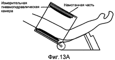
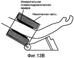
На фиг. 13A и 13B представлены схематичные изображения, демонстрирующие фиксацию измерительной пневмогидравлической камеры, когда артериальное давление измеряют с использованием измерителя артериального давления, на котором смонтировано устройство для сжатия и фиксации тела живого организма. Как показано на фиг. 13A, объект измерения вставляет плечо, служащее областью измерения в обойму. В обойме обеспечены измерительная пневмогидравлическая камера и обертывающая часть, выполняющая функцию пневмогидравлической камеры, и обойма расположена под углом, под которым плечо легко вставить в измеритель артериального давления. Когда выдается команда на начало измерения, то, как показано на фиг. 13B, в обертывающую часть подается текучая среда для накачивания обертывающей части, и измерительная пневмогидравлическая камера прижимается к плечу с, по существу, равномерным давлением в окружном направлении и продольном направлении плеча.In FIG. 13A and 13B are schematic views illustrating the fixation of a measurement pneumohydraulic chamber when blood pressure is measured using a blood pressure meter on which a device for compressing and fixing the body of a living organism is mounted. As shown in FIG. 13A, the measurement object inserts a shoulder serving as a measurement region into a ferrule. The holder is provided with a measuring pneumohydraulic chamber and a wrapping part that performs the function of a pneumohydraulic chamber, and the holder is located at an angle at which the shoulder is easily inserted into the blood pressure monitor. When a command to start the measurement is issued, then, as shown in FIG. 13B, fluid is pumped into the wrapping portion to inflate the wrapping portion, and the measuring pneumohydraulic chamber is pressed against the shoulder with substantially uniform pressure in the circumferential direction and the longitudinal direction of the shoulder.
Патентный документ 1: Выложенная японская заявка № 2005-230175Patent Document 1: Japanese Patent Application Laid-Open No. 2005-230175
РАСКРЫТИЕ ИЗОБРЕТЕНИЯSUMMARY OF THE INVENTION
ПРОБЛЕМЫ, РЕШАЕМЫЕ ИЗОБРЕТЕНИЕМPROBLEMS SOLVED BY THE INVENTION
Однако поскольку в механизме устройства для сжатия и фиксации тела, описанного в патентном документе 1, измерительная пневмогидравлическая камера сжимается по существу равномерным давлением в окружном направлении плеча, независимо от окружности плеча, являющегося областью измерения, как показано на фиг. 13B, то измерительная пневмогидравлическая камера сильнее накачивается для лица с меньшей окружностью плеча, и иногда локтевая часть приподнимается направленным вверх прижимным усилием обертывающей части. В таких случаях, к сожалению, плечо не фиксируется к измерителю артериального давления, и иногда результат измерения нельзя получить правильно из-за нестабильного положения при измерении.However, since in the mechanism of the body compression and fixing device described in
Кроме того, в механизме устройства для сжатия и фиксации тела измерительная пневмогидравлическая камера сжимается по существу равномерным давлением в продольном направлении плеча, независимо от окружности плеча, являющейся областью измерения. Поэтому для лица с плечом сужающейся формы, когда измерительная пневмогидравлическая камера сжимается с базированием на толстой стороне плеча сужающейся формы, измерительная пневмогидравлическая камера иногда неправильно прижимается к тонкой стороне плеча сужающейся формы. Когда измерительная пневмогидравлическая камера сжимается с базированием на тонкой стороне плеча сужающейся формы для фиксации измерительной пневмогидравлической камеры на всей области измерения, измерительная пневмогидравлическая камера иногда слишком сильно прижимается к тонкой стороне плеча сужающейся формы. В таких случаях, к сожалению, измерительная пневмогидравлическая камера неправильно прижимается к области измерения, и иногда невозможно получить правильный результат измерения.In addition, in the mechanism of the device for compressing and fixing the body, the measuring pneumohydraulic chamber is compressed by substantially uniform pressure in the longitudinal direction of the shoulder, regardless of the circumference of the shoulder, which is the measurement area. Therefore, for a person with a tapering shoulder, when the measuring pneumohydraulic chamber is compressed based on the thick side of the tapering shoulder, the measuring pneumatic chamber is sometimes incorrectly pressed to the thin side of the tapering shoulder. When the measuring pneumohydraulic chamber is compressed based on the thin side of the shoulder of the tapering shape to fix the measuring pneumohydraulic chamber throughout the measurement area, the measuring pneumohydraulic chamber is sometimes too pressed against the thin side of the shoulder of the tapering shape. In such cases, unfortunately, the measuring pneumohydraulic chamber is incorrectly pressed to the measurement area, and sometimes it is impossible to obtain the correct measurement result.
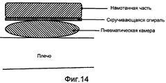
Кроме того, в механизме устройства для сжатия и фиксации тела, как показано на фиг. 14, измерительная пневмогидравлическая камера накачивается подачей текучей среды, и тело живого организма сжимается со стороны внешней окружности измерительной пневмогидравлической камерой (пневматической камерой), сечение которой приобретает круглую или овальную форму вследствие накачивания, в плоскости, образованной гибким элементом, например скручивающейся спиралью. Поэтому прижимное усилие обертывающей части иногда не действует на участок, находящийся в стороне от центра измерительной пневмогидравлической камеры, в зависимости от формы сечения измерительной пневмогидравлической камеры и формы гибкого элемента, охватывающего измерительную пневмогидравлическую камеру. В таких случаях, как показано на фиг. 14, измерительная пневмогидравлическая камера иногда не прижимается к артерии в необходимом интервале, что создает проблему неполучения точного результата измерения.In addition, in the mechanism of the device for compressing and fixing the body, as shown in FIG. 14, the measuring pneumohydraulic chamber is pumped up by supplying a fluid, and the body of a living organism is compressed from the outer circumference by the measuring pneumohydraulic chamber (pneumatic chamber), the cross section of which takes a round or oval shape due to pumping, in a plane formed by a flexible element, for example, a twisting spiral. Therefore, the clamping force of the wrapping part sometimes does not act on the section located away from the center of the measuring pneumatic-hydraulic chamber, depending on the cross-sectional shape of the measuring pneumatic-hydraulic chamber and the shape of the flexible element covering the measuring pneumatic-hydraulic chamber. In such cases, as shown in FIG. 14, the measuring pneumohydraulic chamber sometimes does not press against the artery in the required interval, which creates the problem of not receiving an accurate measurement result.
С учетом вышеизложенного, целью настоящего изобретения является создание устройства для измерения артериального давления, правильно прижимающего измерительную пневмогидравлическую камеру к области измерения.In view of the foregoing, the aim of the present invention is to provide a device for measuring blood pressure, correctly pressing the measuring pneumohydraulic chamber to the measurement area.
СРЕДСТВА ДЛЯ ДОСТИЖЕНИЯ УКАЗАННЫХ ПРОБЛЕМMEANS FOR ACHIEVING THE PROBLEMS PROVIDED
В соответствии с одним аспектом настоящего изобретения устройство для измерения артериального давления содержит измерительную пневмогидравлическую камеру, соответствующую измерительной пневматической камере 13; первую подающую часть, соответствующую насосу 21, клапану 22, управляющей схеме 26 насоса и управляющей схеме 27 клапана, для подачи текучей среды в измерительную пневмогидравлическую камеру; датчик, соответствующий датчику 23 давления для измерения внутреннего давления измерительной пневмогидравлической камеры; часть для сжатия измерительной пневмогидравлической камеры, соответствующую сжимающей и фиксирующей пневматической камере 8 и проводу 81, для сжатия измерительной пневмогидравлической камеры в области измерения и датчик степени сжатия, соответствующий датчику 33, для измерения степени, с которой измерительная пневмогидравлическая камера сжимается частью для сжатия измерительной пневмогидравлической камеры, при этом часть для сжатия измерительной пневмогидравлической камеры содержит первую сжимающую часть для сжатия измерительной пневмогидравлической камеры с воздействием в первом режиме сжатия и вторую сжимающую часть для сжатия измерительной пневмогидравлической камеры с воздействием во втором режиме сжатия.In accordance with one aspect of the present invention, a device for measuring blood pressure includes a measuring pneumohydraulic chamber corresponding to the measuring
В предпочтительном варианте устройство для измерения артериального давления дополнительно содержит контроллер, соответствующий CPU (центральному процессору) 40, для управления сжатием измерительной пневмогидравлической камеры в части для сжатия измерительной пневмогидравлической камеры, при этом контроллер осуществляет управление так, что первая сжимающая часть сжимается с использованием измерительной пневмогидравлической камеры с воздействием в первом режиме сжатия, и контроллер осуществляет управление так, что вторая сжимающая часть сжимается с использованием измерительной пневмогидравлической камеры с воздействием во втором режиме сжатия.In a preferred embodiment, the blood pressure measuring device further comprises a controller corresponding to the CPU (central processing unit) 40 for controlling the compression of the measuring pneumatic chamber into a part for compressing the measuring pneumatic chamber, while the controller controls so that the first compressing part is compressed using the measuring pneumohydraulic cameras with exposure in the first compression mode, and the controller controls so that the second compression h The part is compressed using a measuring pneumohydraulic chamber with exposure in the second compression mode.
Точнее, контроллер предпочтительно управляет сжатием в части для сжатия измерительной пневмогидравлической камеры с учетом внутреннего давления измерительной пневмогидравлической камеры, информации, указывающей изменение внутреннего давления в измерительной пневмогидравлической камере, и степени сжатия части для сжатия измерительной пневмогидравлической камеры.More specifically, the controller preferably controls the compression in the compression part of the measuring pneumatic chamber, taking into account the internal pressure of the measuring pneumatic chamber, information indicating the change in internal pressure in the measuring pneumatic chamber, and the compression ratio of the part for compressing the measuring chamber.
В частности, в предпочтительном варианте часть для сжатия измерительной пневмогидравлической камеры представляет собой сжимающую пневмогидравлическую камеру, устройство для измерения артериального давления дополнительно содержит вторую подающую часть для подачи текучей среды в первую сжимающую пневмогидравлическую камеру, выполняющую функцию первой сжимающей части; и третью подающую часть для подачи текучей среды во вторую сжимающую пневмогидравлическую камеру, выполняющую функцию второй сжимающей части, и контроллер управляет подачей текучей среды во вторую подающую часть и третью подающую часть для управления сжатием в части для сжатия измерительной пневмогидравлической камеры.In particular, in a preferred embodiment, the compression part of the measuring pneumohydraulic chamber is a compressing pneumatic chamber, the blood pressure measuring device further comprises a second supply part for supplying fluid to the first compressing pneumatic chamber, acting as a first compressing part; and a third feed portion for supplying fluid to the second compressing pneumohydraulic chamber, which functions as a second compressing portion, and the controller controls the flow of fluid to the second feed portion and the third feed portion for controlling compression in the compression portion of the measuring pneumatic-hydraulic chamber.
В частности, в предпочтительном варианте область измерения является плечом, первая сжимающая часть и вторая сжимающая часть расположены ортогонально относительно артерии в плече, когда измерительная пневмогидравлическая камера наложена на плечо, при этом первая сжимающая часть размещена в положении, в котором измерительная пневмогидравлическая камера, находящаяся выше плеча, поджимается сверху к плечу, тогда как вторая сжимающая часть размещена в положении, в котором измерительная пневмогидравлическая камера, находящаяся ниже плеча, поджимается снизу к плечу, и контроллер осуществляет управление так, чтобы первая сжимающая часть сжимала измерительную пневмогидравлическую камеру и затем вторая сжимающая часть сжимала измерительную пневмогидравлическую камеру.In particular, in a preferred embodiment, the measuring region is the shoulder, the first compressing part and the second compressing part are located orthogonally relative to the artery in the shoulder when the measuring pneumohydraulic chamber is superimposed on the shoulder, while the first compressing part is placed in the position in which the measuring pneumohydraulic chamber is located above shoulder, is pressed from above to the shoulder, while the second compressing part is placed in a position in which the measuring pneumohydraulic chamber below the shoulder , is pressed from the bottom to the shoulder, and the controller controls so that the first compressing part compresses the measuring pneumohydraulic chamber and then the second compressing part compresses the measuring pneumohydraulic chamber.
В альтернативном предпочтительном варианте область измерения является плечом, и первая сжимающая часть и вторая сжимающая часть расположены параллельно артерии в плече, когда измерительная пневмогидравлическая камера наложена на плечо, при этом первая сжимающая часть размещена в положении ближе к плечевому составу в верхней части плеча, тогда как вторая сжимающая часть размещена в положении ближе к запястью в нижней части плеча.In an alternative preferred embodiment, the measurement region is the shoulder, and the first compression part and the second compression part are parallel to the artery in the shoulder when the measuring pneumohydraulic chamber is placed on the shoulder, while the first compression part is placed in a position closer to the shoulder composition in the upper part of the shoulder, while the second compressive part is placed in a position closer to the wrist in the lower part of the shoulder.
В предпочтительном варианте контроллер осуществляет управление так, чтобы степень сжатия во второй сжимающей части была больше, чем степень сжатия в первой сжимающей части.In a preferred embodiment, the controller controls so that the compression ratio in the second compression portion is greater than the compression ratio in the first compression portion.
В альтернативном предпочтительном варианте область измерения является плечом, и первая сжимающая часть и вторая сжимающая часть расположены параллельно артерии в плече, когда измерительная пневмогидравлическая камера наложена на плечо, при этом первая сжимающая часть размещена, по существу, по центру, в направлении, параллельном артерии, измерительной пневмогидравлической камеры, тогда как вторая сжимающая часть размещена в положении ближе к краю, чем к центру, в направлении, параллельном артерии, измерительной пневмогидравлической камеры, и контроллер осуществляет управление так, чтобы степень сжатия во второй сжимающей части была больше, чем степень сжатия в первой сжимающей части.In an alternative preferred embodiment, the measurement area is the shoulder, and the first compression part and the second compression part are parallel to the artery in the shoulder when the measuring pneumohydraulic chamber is laid on the shoulder, while the first compression part is placed essentially in the center, in a direction parallel to the artery, measuring pneumohydraulic chamber, while the second compressing part is placed in a position closer to the edge than to the center, in a direction parallel to the artery, measuring pneumohydraulic to measures, and the controller controls so that the compression ratio in the second compression portion is greater than the compression ratio in the first compression portion.
В альтернативном предпочтительном варианте первая сжимающая часть является частью, соответствующей первой характеристике части для сжатия измерительной пневмогидравлической камеры, и первая сжимающая часть действует в первом режиме сжатия в соответствии с первой характеристикой, тогда как вторая сжимающая часть является частью, соответствующей второй характеристике части для сжатия измерительной пневмогидравлической камеры, и вторая сжимающая часть действует во втором режиме сжатия в соответствии со второй характеристикой.In an alternative preferred embodiment, the first compression part is a part corresponding to the first characteristic of the compression part of the measuring pneumatic chamber, and the first compression part acts in the first compression mode in accordance with the first characteristic, while the second compression part is the part corresponding to the second characteristic of the measuring part of the measuring pneumohydraulic chamber, and the second compression part operates in the second compression mode in accordance with the second characteristic.
Точнее, в предпочтительном варианте, часть для сжатия измерительной пневмогидравлической камеры является сжимающей пневмогидравлической камерой, и первая характеристика и вторая характеристика зависят от числа швов сжимающей пневмогидравлической камеры.More precisely, in a preferred embodiment, the compression part of the measuring pneumatic chamber is a compressing pneumatic chamber, and the first characteristic and the second characteristic depend on the number of seams of the compressing pneumatic chamber.
ЭФФЕКТЫ ИЗОБРЕТЕНИЯEFFECTS OF THE INVENTION
Устройство для измерения артериального давления в соответствии с настоящим изобретением содержит средство сжатия измерительной пневмогидравлической камеры для сжимания измерительной пневмогидравлической камеры, соответствующей манжете, для прижима измерительной пневмогидравлической камеры к области измерения, при этом средство сжатия измерительной пневмогидравлической камеры содержит множество режимов сжатия, и средство сжатия измерительной пневмогидравлической камеры сжимает измерительную пневмогидравлическую камеру в разных режимах сжатия в направлении, ортогональном и/или параллельном артерии в области измерения. Поэтому можно предотвратить дестабилизацию положения при измерении, вызываемую приподниманием области измерения при сжатии измерительной пневмогидравлической камеры. Измерительная пневмогидравлическая камера может правильно фиксироваться согласно форме области измерения, например суженной форме. Измерительная пневмогидравлическая камера, в которую подается текучая среда, может правильно сжиматься в необходимом интервале, и артерия может быть прижата правильно. Соответственно, может быть повышена точность измерения.A blood pressure measuring device in accordance with the present invention comprises means for compressing a measuring pneumohydraulic chamber for compressing a measuring pneumohydraulic chamber corresponding to a cuff, for pressing a measuring pneumohydraulic chamber to a measurement region, wherein means for compressing a measuring pneumohydraulic chamber contains a plurality of compression modes, and compression means for measuring the pneumatic chamber compresses the measuring pneumatic chamber at times s compression behaviors in the direction orthogonal and / or parallel to the artery of the measurement region. Therefore, it is possible to prevent the destabilization of the position during measurement caused by the raising of the measurement area during compression of the measuring pneumohydraulic chamber. The measuring pneumohydraulic chamber can be correctly fixed according to the shape of the measuring area, for example a narrowed shape. The measuring pneumohydraulic chamber, into which the fluid is supplied, can be correctly compressed in the required interval, and the artery can be pressed correctly. Accordingly, the accuracy of the measurement can be improved.
КРАТКОЕ ОПИСАНИЕ ЧЕРТЕЖЕЙBRIEF DESCRIPTION OF THE DRAWINGS
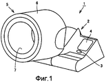
Фиг. 1 - вид в перспективе, представляющий конкретный пример внешнего вида измерителя 1 артериального давления.FIG. 1 is a perspective view showing a specific example of the appearance of a
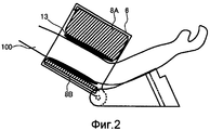
Фиг. 2 - схематичный вид в разрезе, представляющий измеритель 1 артериального давления в соответствии с первым вариантом осуществления в ходе измерения артериального давления.FIG. 2 is a schematic sectional view showing a
Фиг. 3 - вид в разрезе, иллюстрирующий внутреннюю конструкцию измерительной части 5 измерителя 1 артериального давления в соответствии с первым вариантом осуществления.FIG. 3 is a sectional view illustrating an internal structure of the
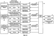
Фиг. 4 - блок-схема, представляющая конкретный пример функциональной конфигурации измерителя 1 артериального давления в соответствии с первым вариантом осуществления.FIG. 4 is a block diagram representing a specific example of a functional configuration of a
Фиг. 5 - блок-схема последовательности операций процесса измерения артериального давления в измерителе 1 артериального давления в соответствии с первым вариантом осуществления.FIG. 5 is a flowchart of a blood pressure measurement process in a
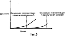
Фиг. 6 - изображение флуктуаций внутренних давлений сжимающих и фиксирующих пневматических камер 8A и 8B в процессе измерения артериального давления.FIG. 6 is a depiction of fluctuations in the internal pressures of the compressing and fixing
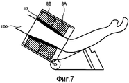
Фиг. 7 - схематичный вид в разрезе, представляющий состояние, в котором артериальное давление измеряют с использованием измерителя 1 артериального давления в соответствии со вторым вариантом осуществления.FIG. 7 is a schematic sectional view showing a state in which blood pressure is measured using a
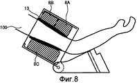
Фиг. 8 - схематичный вид в разрезе, представляющий состояние, в котором артериальное давление измеряют с использованием измерителя 1 артериального давления в соответствии с модификацией первого и второго вариантов осуществления.FIG. 8 is a schematic sectional view showing a state in which blood pressure is measured using a
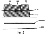
Фиг. 9 - изображение конфигурации сжимающей и фиксирующей пневматической камеры 8 измерителя 1 артериального давления в соответствии с третьим вариантом осуществления и взаимного относительного расположения сжимающей и фиксирующей пневматической камеры 8, скручивающейся части 10, измерительной пневматической камеры 13 и плеча.FIG. 9 is a configuration view of a compression and fixing
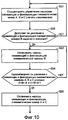
Фиг. 10 - блок-схема последовательности операций процесса накачивания сжимающей и фиксирующей пневматической камеры 8 в процессе измерения артериального давления, выполняемом измерителем 1 артериального давления в соответствии с третьим вариантом осуществления.FIG. 10 is a flowchart of a process for pumping a compressing and fixing
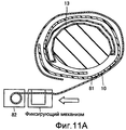
Фиг. 11A - изображение механизма средства сжатия измерительной пневмогидравлической камеры, содержащейся в измерителе 1 артериального давления в соответствии с первой модификацией.FIG. 11A is a depiction of the mechanism of the compression means of the measuring pneumohydraulic chamber contained in the
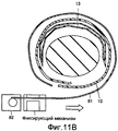
Фиг. 11B - изображение механизма средства сжатия измерительной пневмогидравлической камеры, содержащейся в измерителе 1 артериального давления в соответствии с первой модификацией.FIG. 11B is an image of the mechanism of the compression means of the measuring pneumohydraulic chamber contained in the
Фиг. 12 - изображение конфигурации сжимающей и фиксирующей пневматической камеры 8, содержащейся в измерителе 1 артериального давления в соответствии со второй модификацией.FIG. 12 is a view of a configuration of a compressing and fixing
Фиг. 13A - схематичное изображение фиксации манжеты в традиционном измерителе артериального давления, имеющем конфигурацию, в которой две пневмогидравлических камеры, независимо обеспеченных через посредство скручивающейся спирали, служат как для наложения манжеты, так и для измерения артериального давления.FIG. 13A is a schematic illustration of cuff fixation in a conventional blood pressure monitor having a configuration in which two pneumohydraulic chambers independently provided through a twisting coil serve both to apply the cuff and to measure blood pressure.
Фиг. 13B - схематичное изображение фиксации манжеты, когда измерение артериального давления выполняется с использованием традиционного измерителя артериального давления, имеющего конфигурацию, в которой две пневмогидравлических камеры, независимо обеспеченных через посредство скручивающейся спирали, служат как для наложения манжеты, так и для измерения артериального давления.FIG. 13B is a schematic depiction of cuff fixation when blood pressure measurement is performed using a traditional blood pressure meter having a configuration in which two pneumohydraulic chambers independently provided through a twisting spiral serve both to apply the cuff and to measure blood pressure.
Фиг. 14 - изображение сжатия традиционной измерительной пневмогидравлической камеры.FIG. 14 is a compression image of a conventional measuring pneumohydraulic chamber.
ОПИСАНИЕ УСЛОВНЫХ ОБОЗНАЧЕНИЙDESCRIPTION OF CONVENTIONS
1 - измеритель артериального давления, 2 - основной корпус, 3 - управляющая часть, 4 - дисплей, 5 - измерительная часть, 6 - обойма, 7 - оболочка, 13 - измерительная пневматическая камера, 10 - скручивающаяся спираль, 8 и 8A-8C - сжимающая и фиксирующая пневматическая камера, 20 - измерительная пневматическая система, 23, 33A и 33B - датчик давления, 21, 31A и 31B - насос, 22, 32A и 32B - клапан, 26, 36A и 36B - управляющая схема насоса, 27, 37A и 37B - управляющая схема клапана, 28, 38A и 38B - усилитель, 29, 39A и 39B - A/D (аналого-цифровой) преобразователь, 30A и 30B - сжимающая и фиксирующая пневматическая система, 40 - CPU (центральный процессор), 41 - память, 81 - провод, 82 - часть для намотки провода, 100 - плечо.1 - blood pressure meter, 2 - main body, 3 - control part, 4 - display, 5 - measuring part, 6 - clip, 7 - shell, 13 - measuring pneumatic chamber, 10 - twisting spiral, 8 and 8A-8C - compressing and fixing pneumatic chamber, 20 - measuring pneumatic system, 23, 33A and 33B - pressure sensor, 21, 31A and 31B - pump, 22, 32A and 32B - valve, 26, 36A and 36B - pump control circuit, 27, 37A and 37B - valve control circuit, 28, 38A and 38B - amplifier, 29, 39A and 39B - A / D (analog-to-digital) converter, 30A and 30B - compressing and fixing pneumatic system, 40 - CPU (central processor), 41 - memory, 81 - wire, 82 - part for winding the wire, 100 - shoulder.
НАИЛУЧШИЕ ВАРИАНТЫ ОСУЩЕСТВЛЕНИЯ ИЗОБРЕТЕНИЯBEST MODES FOR CARRYING OUT THE INVENTION
Ниже приведено подробное описание вариантов осуществления настоящего изобретения со ссылками на чертежи. На нижеприведенных чертежах одинаковые компонент и составляющая обозначены одной и той же ссылочной позицией, и одинаковые компонент и составляющая имеют одно и то же название и одну и ту же функцию.The following is a detailed description of embodiments of the present invention with reference to the drawings. In the drawings below, the same component and component are denoted by the same reference position, and the same component and component have the same name and the same function.
Как показано на фиг. 1, устройство 1 для измерения артериального давления (далее именуемого измерителем артериального давления) в соответствии с настоящим вариантом осуществления, в основном, содержит основной корпус 2, устанавливаемый на столе или чем-то подобном, и измерительную часть 5 для обеспечения возможности использования плеча в качестве области измерения посредством вставки в упомянутую измерительную часть. Управляющая часть 3, дисплей 4 и держатель локтя обеспечены в верхнем участке основного корпуса 2. Кнопка питания и кнопка измерения расположены в управляющей части 3. Измерительная часть 5 присоединена к основному корпусу 2, при этом возможно регулирование угла измерительной части 5 относительно основного корпуса 2, и измерительная часть 5 содержит обойму 6 и устройство, сжимающее и фиксирующее тело. Обойма 6 представляет собой по существу цилиндрический каркас, и устройство для сжатия и фиксации тела вмещается во внутренний окружной участок обоймы 6. Как показано на фиг. 1, устройство для сжатия и фиксации тела, вмещенное во внутренний окружной участок обоймы 6, не открыто наружу в состоянии нормального применения, а закрыто оболочкой 7.As shown in FIG. 1, a blood pressure measuring device 1 (hereinafter referred to as a blood pressure meter) in accordance with the present embodiment basically comprises a
[Первый вариант осуществления][First Embodiment]
Как показано на фиг. 2, при измерении артериального давления плечо 100 вставляют в обойму 6 для установки плеча на держатель плеча и выдают команду на начало измерения. Плечо 100 сжимается и фиксируется устройством для сжатия и фиксации тела для измерения артериального давления.As shown in FIG. 2, when measuring blood pressure, the
Устройство для сжатия и фиксации тела содержит измерительную пневматическую камеру 13, скручивающуюся спираль 10 (см. фиг. 3) и сжимающую и фиксирующую пневматическую камеру 8. Измерительная пневматическая камера 13, соответствующая манжете, представляющая собой измерительную пневмогидравлическую камеру, сжимает область измерения для измерения артериального давления. Скручивающаяся спираль 10 является по существу цилиндрическим гибким элементом, расположенным снаружи измерительной пневматической камеры 13, и скручивающаяся спираль 10 может радиально расширяться и сжиматься. Сжимающая и фиксирующая пневматическая камера 8 выполняет функцию средства сжатия измерительной пневмогидравлической камеры, расположенного снаружи скручивающейся спирали 10, накачивание сжимающей и фиксирующей пневматической камеры 8 создает нажим внутрь на внешнюю окружную поверхность скручивающейся спирали 10 и, тем самым, уменьшает диаметр скручивающейся спирали 10, и, в сочетании с обоймой 8, сжимающая и фиксирующая пневматическая камера 8 сжимает измерительную пневматическую камеру 13 через посредство скручивающейся спирали 10 и, тем самым, прижимает измерительную пневматическую камеру 13 к области измерения на теле.The device for compressing and fixing the body contains a measuring
В измерителе 1 артериального давления в соответствии с первым вариантом осуществления сжимающая и фиксирующая пневматическая камера 8 содержит множество сжимающих и фиксирующих пневматических камер, расположенных в направлении по окружности плеча, ортогонально артерии плеча, и сжимающие и фиксирующие пневматические камеры воздействуют в разных режимах сжатия благодаря раздельному управлению подачей/выпуском воздуха. В настоящем случае, в частности, предполагается, что сжимающая и фиксирующая пневматическая камера 8 содержит две сжимающих и фиксирующих пневматических камеры 8A и 8B. Когда плечо вставлено в обойму 6, сжимающая и фиксирующая пневматическая камера 8A расположена выше плеча, тогда как сжимающая и фиксирующая пневматическая камера 8B расположена ниже плеча.In the
Как показано на фиг. 3, в измерительной части 5 сжимающие и фиксирующие пневматические камеры 8A и 8B содержатся внутри обоймы 6, и сжимающие и фиксирующие пневматические камеры 8A и 8B накачиваются и сжимаются, соответственно, сжимающими и фиксирующими пневматическими системами 30A и 30B (см. фиг. 4).As shown in FIG. 3, in the measuring
Скручивающаяся спираль 10, сформированная листообразным элементом, завернутым, по существу, в форме цилиндра, расположена внутри сжимающей и фиксирующей пневматической камеры 8, и скручивающаяся спираль 10 упруго деформируется в радиальном направлении при приложении внешнего усилия. Измерительная пневматическая камера 13 расположена внутри скручивающейся спирали 10 и накачивается и скачивается измерительной пневматической системой 20 (см. фиг. 4), которая описана далее.A twisting
Как показано на фиг. 4, измеритель 1 артериального давления содержит измерительную пневматическую камеру 13 и сжимающие и фиксирующие пневматические камеры 8A и 8B, и измерительная пневматическая камера 13 и сжимающие и фиксирующие пневматические камеры 8A и 8B подсоединены, соответственно, к измерительной пневматической системе 20 и сжимающим и фиксирующим пневматическим системам 30A и 30B. Измерительная пневматическая система 20 содержит датчик 23 давления, измеряющий внутреннее давление измерительной пневматической камеры 13, насос 21, подающий воздух в измерительную пневматическую камеру 13 и выпускающий воздух из нее, и клапан 22. Сжимающие и фиксирующие пневматические системы 30A и 30B содержат датчики 33A и 33B давления, измеряющие внутренние давления сжимающих и фиксирующих пневматических камер 8A и 8B, насосы 31A и 31B, подающие воздух в сжимающие и фиксирующие пневматические камеры 8A и 8B и выпускающие воздух из них, и, соответственно, насосы 32A и 32B.As shown in FIG. 4, the
Измеритель 1 артериального давления содержит CPU (центральный процессор) 40, управляющий всем измерителем 1 артериального давления, усилитель 28, подсоединенный к измерительной пневматической системе 20, управляющую схему 26 насоса и управляющую схему 27 клапана, усилители 38A и 38B, управляющие схемы 36A и 36B насосов, управляющие схемы 37A и 37B клапанов, соединенные с, соответственно, сжимающими и фиксирующими пневматическими камерами 8A и 8B, A/D (аналого-цифровые) преобразователи 29, 39A и 39B, соединенные, соответственно, с усилителями 28, 38A и 38B, память 41, в которой сохраняются программа, исполняемая CPU 40, и результат измерения, дисплей 4, отображающий результат измерения, и управляющую часть 3, содержащую кнопку начала измерения, кнопку прекращения измерения и т.п.
CPU 40 исполняет заданную программу, сохраненную в памяти 41, по управляющему сигналу, вводимому с управляющей части 3, и CPU 40 выдает управляющий сигнал в управляющие схемы 26, 36A и 36B насосов и управляющие схемы 27, 37A и 37B клапанов. Управляющие схемы 26, 36A и 36B насосов и управляющие схемы 27, 37A и 37B клапанов управляют насосами 21, 31A и 31B и клапанами 22, 32A и 32B в соответствии с управляющим сигналом для выполнения процесса измерения артериального давления.The
Датчик 23 давления снимает внутреннее давление измерительной пневматической камеры 13 и вводит снятый сигнал в усилитель 28. Датчики 33A и 33B давления, соответствующие средству для измерения степени сжатия, снимают внутренние давления сжимающих и фиксирующих пневматических камер 8A и 8B и вводят снятый сигнал в усилители 38A и 38B. Внутренние давления сжимающих и фиксирующих пневматических камер 8A и 8B соответствуют степени сжатия измерительной пневмогидравлической камеры, сжатой средством сжатия измерительной пневмогидравлической камеры. Вводимые сигналы соответственно усиливаются до заданных амплитуд усилителями 28, 38A и 38B и преобразуются в цифровые сигналы A/D-преобразователями 29, 39A и 39B, и цифровые сигналы вводятся в CPU 40.The
CPU 40 выполняет заданный процесс на основании внутренних давлений измерительной пневматической камеры 13 и сжимающих и фиксирующих пневматических камер 8A и 8B, которые получены из датчиков 23, 33A и 33B давления, и CPU 40 выдает управляющий сигнал в управляющие схемы 26, 36A и 36B насосов и управляющие схемы 27, 37A и 37B клапанов в соответствии с результатом процесса. CPU 40 выводит значение артериального давления на основании внутреннего давления измерительной пневматической камеры 13, полученного от датчика 23 давления, и выдает результат измерения для его отображения на дисплее 4.The
CPU 40 считывает и исполняет программу, сохраненную в памяти 41, и управляет каждым блоком, показанным на фиг. 4, и, тем самым, реализует процесс измерения артериального давления, показанный на фиг. 5 в форме блок-схемы последовательности операций, исполняемых измерителем 1 артериального давления.The
Как показано на фиг. 5, на этапе S11 выполняется инициализация таким образом, что опорное значение датчика устанавливается равным атмосферному давлению, и затем нагнетается предварительное давление в измерительной пневматической камере 13. На этапе S12 CPU 40 выдает управляющий сигнал в управляющую схему 36A насоса и управляющую схему 37A клапана для управления управляющей схемой 36A насоса и управляющей схемой 37A клапана, и CPU 40 начинает нагнетать давление в сжимающей и фиксирующей пневматической камере 8A. CPU 40 контролирует внутреннее давление в сжимающей и фиксирующей пневматической камере 8A, получаемое от датчика 33A давления. Когда внутреннее давление достигает заданного первого порога (ДА на этапе S13), CPU 40 выдает управляющий сигнал в управляющую схему 36A насоса и управляющую схему 37A клапана, чтобы прекратить нагнетание давления в сжимающей и фиксирующей пневматической камере 8A на этапе S14. CPU 40 дополнительно выдает управляющий сигнал в управляющую схему 36B насоса и управляющую схему 37B клапана для управления управляющей схемой 36B насоса и управляющей схемой 37B клапана, и CPU 40 начинает нагнетание давления в сжимающей и фиксирующей пневматической камере 8B.As shown in FIG. 5, in step S11, initialization is performed so that the reference value of the sensor is set to atmospheric pressure, and then pre-pressure is pumped into the measuring
Когда на этапе S14 начинается нагнетание давления в сжимающей и фиксирующей пневматической камере 8B, CPU 40 контролирует внутреннее давление в сжимающей и фиксирующей пневматической камере 8B. Сжимающая и фиксирующая пневматическая камера 8B накачивается и поджимается для повышения внутреннего давления в сжимающей и фиксирующей пневматической камере 8B. Когда внутреннее давление в сжимающей и фиксирующей пневматической камере 8B достигает заданного второго порога (ДА на этапе S15), CPU 40 выдает управляющий сигнал в управляющую схему 36A насоса и управляющую схему 37A клапана для управления управляющей схемой 36A насоса и управляющей схемой 37A клапана, и CPU 40 нагнетает давление как в сжимающей и фиксирующей пневматической камере 8B, так и в сжимающей и фиксирующей пневматической камере 8A на этапе S17. В альтернативном варианте CPU 40 контролирует внутреннее давление в сжимающей и фиксирующей пневматической камере 8A вместо внутреннего давления в сжимающей и фиксирующей пневматической камере 8B на этапе S15, и CPU 40 может выдавать управляющий сигнал в управляющую схему 36A насоса и управляющую схему 37A клапана, когда внутреннее давление в сжимающей и фиксирующей пневматической камере 8A достигает заданного второго порога на этапе S17.When the pressurization in the compressing and fixing
Во время нагнетания давления в сжимающих и фиксирующих пневматических камерах 8A и 8B CPU 40 контролирует внутреннее давление в измерительной пневматической камере 13 и изменение внутреннего давления в измерительной пневматической камере 13, полученного от датчика 23 давления. Когда данные значения достигают заданных значений (ДА на этапе S18), CPU 40 заканчивает нагнетание давления в сжимающих и фиксирующих камерах 8A и 8B на этапе S19.During pressurization in the compressing and fixing
На этапе S20 CPU 40 выдает управляющий сигнал в управляющую схему 26 насоса и управляющую схему 27 клапана для управления управляющей схемой 26 насоса и управляющей схемой 27 клапана и CPU 40 нагнетает давление в измерительной пневматической камере 13. Когда CPU 40 определяет, что внутреннее давление в измерительной пневматической камере 13 достигает заданного значения настройки нагнетаемого давления (ДА на этапе S21), CPU 40 начинает сбрасывать давление в измерительной пневматической камере 13 на этапе S22.In step S20, the
На этапе S23 CPU 40 вычисляет артериальное давление по внутреннему давлению в измерительной пневматической камере 13, которое получено от датчика 23 давления при нагнетании давления в измерительной пневматической камере 13 на этапе S22. На этапе S24 CPU 40 предписывает дисплею 4 отобразить артериальное давление. На этапе S25 выполняется выпуск воздуха из сжимающей и фиксирующей пневматической камеры 8 и воздуха из измерительной пневматической камеры 13 для ослабления сжатия тела.In step S23, the
В конфигурации в соответствии с настоящим вариантом осуществления артериальное давление вычисляется по внутреннему давлению в измерительной пневматической камере 13, полученному от датчика 23 давления в процессе сброса давления. В альтернативном варианте артериальное давление может вычисляться по внутреннему давлению в измерительной пневматической камере 13, полученному от датчика 23 давления не в процессе сброса давления, а в процессе нагнетания давления.In the configuration of the present embodiment, the blood pressure is calculated from the internal pressure in the
Вышеописанное управление осуществляется измерителем 1 артериального давления в соответствии с первым вариантом осуществления, при нагнетании, тем самым, давления в пневматической камере, как показано на фиг. 6.The above control is carried out by the
Как показано на фиг. 6, когда выдается команда на начало исполнения процесса, управляющая схема 36A насоса управляется так, чтобы подавать воздух в сжимающую и фиксирующую пневматическую камеру 8A, и внутреннее давление повышается на этапе S12. Когда внутреннее давление в сжимающей и фиксирующей пневматической камере 8A достигает заданного значения (ДА на этапе S13), управление управляющей схемой 36A насоса прекращается, и управляющая схема 36B насоса управляется так, чтобы начать нагнетание давления в сжимающей и фиксирующей пневматической камере 8B на этапе S14. Сжимающая и фиксирующая пневматическая камера 8A сжимается в зависимости от накачивания сжимающей и фиксирующей пневматической камеры 8B, что повышает внутреннее давление в сжимающей и фиксирующей пневматической камере 8A. То есть в измерителе 1 артериального давления в соответствии с первым вариантом осуществления, чтобы зафиксировать измерительную пневматическую камеру 13, соответствующую манжете, на теле, сжимающая и фиксирующая пневматическая камера 8A и сжимающая и фиксирующая пневматическая камера 8B воздействуют в разных режимах сжатия при нагнетании давления и накачивании сжимающих и фиксирующих пневматических камер, при этом накачивается сжимающая и фиксирующая пневматическая камера 8A, сжимающая и фиксирующая область измерения сверху, и затем накачивается сжимающая и фиксирующая пневматическая камера 8B, сжимающая и фиксирующая область измерения снизу.As shown in FIG. 6, when a command is issued to start the process, the
Сжимающая и фиксирующая пневматическая камера 8 в соответствии с первым вариантом осуществления должна содержать, по меньшей мере, две сжимающих и фиксирующих пневматических камеры, расположенных в окружном направлении ортогонально относительно артерии в плече. Сжимающие и фиксирующие пневматические камеры воздействуют в разных режимах сжатия благодаря раздельному управлению подачей/выпуском воздуха. Однако настоящее изобретение не ограничено конфигурацией, в которой размещены две сжимающих и фиксирующих пневматических камеры 8A и 8B. В случае, когда сжимающая и фиксирующая пневматическая камера 8 содержит, по меньшей мере, три сжимающих и фиксирующих пневматических камеры, CPU 40 осуществляет управление, аналогичное вышеописанному. То есть CPU 40 раздельно управляет управляющими схемами насосов для подачи воздуха в сжимающие и фиксирующие пневматические камеры, при этом накачивается сжимающая и фиксирующая пневматическая камера, сжимающая и фиксирующая область измерения сверху, и затем накачивается сжимающая и фиксирующая пневматическая камера, сжимающая и фиксирующая область измерения снизу. Из множества сжимающих и фиксирующих пневматических камер некоторые сжимающие и фиксирующие пневматические камеры могут даже воздействовать в одинаковых режимах сжатия, и CPU 40 может осуществлять управление так, чтобы вызывать накачивание, по меньшей мере, сжимающей и фиксирующей пневматической камеры, сжимающей и фиксирующей область измерения сверху, и затем вызывать накачивание сжимающей и фиксирующей пневматической камеры, сжимающей и фиксирующей область измерения снизу.Compressing and fixing
Сжимающая и фиксирующая пневматическая камера 8 измерителя 1 артериального давления в соответствии с первым вариантом осуществления имеет конфигурацию, в которой CPU 40 управляет управляющими схемами насосов вышеописанным образом для воздействия в разных режимах сжатия. Поэтому измерительная пневматическая камера, соответствующая манжете, сжимается сверху на плече, служащем областью измерения, и затем накачивается сжимающая и фиксирующая пневматическая камера, расположенная ниже. Соответственно, даже при нагнетании давления в сжимающей и фиксирующей пневматической камере плечо фиксируется к измерителю 1 артериального давления для поддержки стабильного положения при измерении, так что можно предотвратить искажения, вызываемые смещением тела, и, тем самым, повысить точность измерения артериального давления.The compression and fixing
[Второй вариант осуществления][Second Embodiment]
Как показано на фиг. 7, аналогично измерителю 1 артериального давления в соответствии с первым вариантом осуществления в измерителе 1 артериального давления в соответствии со вторым вариантом осуществления плечо 100 вставляют в обойму 6 для постановки локтя на держатель локтя и выдается команда на начало измерения. Плечо 100 сжимается и фиксируется устройством для сжатия и фиксации тела, чтобы выполнять измерение артериального давления.As shown in FIG. 7, similarly to the
В измерителе 1 артериального давления в соответствии со вторым вариантом осуществления сжимающая и фиксирующая пневматическая камера 8 содержит множество сжимающих и фиксирующих пневматических камер, расположенных в продольном направлении плеча, параллельно артерии плеча, и сжимающие и фиксирующие пневматические камеры воздействуют в разных режимах сжатия благодаря раздельному управлению подачей/выпуском воздуха. В настоящем случае, в частности, предполагается, что сжимающая и фиксирующая пневматическая камера 8 содержит две сжимающих и фиксирующих пневматических камеры 8A и 8B. Когда плечо вставлено в обойму 6, сжимающая и фиксирующая пневматическая камера 8A расположена по окружности плеча ближе к запястью, тогда как сжимающая и фиксирующая пневматическая камера 8B расположена по окружности плеча дальше от запястья.In the
Функциональная конфигурация измерителя 1 артериального давления в соответствии со вторым вариантом осуществления аналогична функциональной конфигурации измерителя 1 артериального давления в соответствии с первым вариантом осуществления, показанным на фиг. 4. В случае, когда артериальное давление измеряют с использованием измерителя 1 артериального давления в соответствии с настоящим вариантом осуществления, исполняется такой же процесс измерения артериального давления, как процесс, исполняемый измерителем 1 артериального давления в соответствии с первым вариантом осуществления и показанный на блок-схеме последовательности операций на фиг. 5.The functional configuration of the blood pressure monitor 1 in accordance with the second embodiment is similar to the functional configuration of the
Как изложено выше, инициализация выполняется на этапе S11, сжимающая и фиксирующая пневматическая камера 8A, расположенная ближе к запястью, нагнетается, пока давление не достигает первого порога на этапах S12 и S13, и нагнетание давления в сжимающей и фиксирующей пневматической камере 8A прекращается, чтобы начать нагнетание давления в сжимающей и фиксирующей пневматической камере 8B на этапе S14. Когда внутреннее давление в сжимающей и фиксирующей пневматической камере 8A или внутреннее давление или изменение внутреннего давления в сжимающей и фиксирующей пневматической камере 8B достигает второго порога, сжимающая и фиксирующая пневматическая камера 8A и сжимающая и фиксирующая пневматическая камера 8B нагнетаются на этапе S17.As described above, initialization is performed in step S11, the compressing and fixing
В измерителе 1 артериального давления в соответствии со вторым вариантом осуществления, благодаря управлению от CPU 40, сжимающая и фиксирующая пневматическая камера 8A и сжимающая и фиксирующая пневматическая камера 8B воздействуют в разных режимах сжатия, когда сжимающие и фиксирующие пневматические камеры нагнетаются и накачиваются, для фиксации измерительной пневматической камеры 13, соответствующей манжете, на теле. То есть нагнетание давления выполняется по-разному в сжимающей и фиксирующей пневматической камере 8A, расположенной ближе к запястью на плече, служащем областью измерения, и сжимающей и фиксирующей пневматической камере 8B, расположенной дальше от запястья.In the
В процессе измерения артериального давления порядок нагнетания давления в сжимающей и фиксирующей пневматической камере 8A и сжимающей и фиксирующей пневматической камере 8B не ограничен, но сжимающая и фиксирующая пневматическая камера 8A нагнетается после нагнетания давления в сжимающей и фиксирующей пневматической камере 8B.In the process of measuring blood pressure, the order of pressurization in the compressing and fixing
Аналогично первому варианту осуществления сжимающая и фиксирующая пневматическая камера 8 в соответствии со вторым вариантом осуществления должна содержать, по меньшей мере, две сжимающих и фиксирующих пневматических камеры, расположенных в продольном направлении параллельно артерии плеча. Сжимающие и фиксирующие пневматические камеры воздействуют в разных режимах сжатия благодаря раздельному управлению подачей/выпуском воздуха. Однако, настоящее изобретение не ограничено конфигурацией, в которой размещены две сжимающих и фиксирующих пневматических камеры 8A и 8B. В случае, когда сжимающая и фиксирующая пневматическая камера 8 содержит, по меньшей мере, три сжимающих и фиксирующих пневматических камеры, CPU 40 осуществляет управление, аналогичное вышеописанному. То есть CPU 40 раздельно управляет управляющими схемами насосов для подачи воздуха в сжимающие и фиксирующие пневматические камеры, и CPU 40 раздельно накачивает сжимающие и фиксирующие пневматические камеры. Из множества сжимающих и фиксирующих пневматических камер некоторые сжимающие и фиксирующие пневматические камеры могут даже воздействовать в одинаковых режимах сжатия, и CPU 40 может управлять накачиванием в соответствии с окружностью плеча в сжимаемой области измерения.Similarly to the first embodiment, the compressing and fixing
Сжимающая и фиксирующая пневматическая камера 8 измерителя 1 артериального давления в соответствии со вторым вариантом осуществления имеет конфигурацию, в которой CPU 40 управляет управляющими схемами насосов вышеописанным образом для воздействия в разных режимах сжатия. Поэтому сжимающая и фиксирующая пневматическая камера может накачиваться в соответствии с формой плеча, служащего областью измерения. Например, даже если плечо, служащее областью измерения, имеет сужающуюся форму, измерительная пневматическая камера может быть правильно сжата и прижата к измерительной области в соответствии с формой измерительной области. Следовательно, можно повысить точность измерения артериального давления.The compressing and fixing
[Модификация первого и второго вариантов осуществления][Modification of the first and second embodiments]
Сжимающая и фиксирующая пневматическая камера 8 может содержать множество сжимающих и фиксирующих пневматических камер, сформированных объединением конфигурации сжимающей и фиксирующей пневматической камеры 8 в соответствии с первым вариантом осуществления и конфигурации сжимающей и фиксирующей пневматической камеры 8 в соответствии со вторым вариантом осуществления. Множество сжимающих и фиксирующих пневматических камер воздействует в разных режимах сжатия благодаря раздельному управлению подачей/выпуском воздуха, и множество сжимающих и фиксирующих пневматических камер расположено в направлении, ортогональном и/или параллельном артерии в плече. В частности, как показано на фиг. 8, сжимающая и фиксирующая пневматическая камера 8 может быть сформирована сжимающими и фиксирующими пневматическими камерами 8A и 8B, расположенными в продольном направлении плеча, и сжимающей и фиксирующей пневматической камерой 8C, расположенной в окружном направлении плеча.The compression and fixing
В измерителе 1 артериального давления в соответствии с модификацией CPU 40 аналогичным образом раздельно управляет управляющими схемами 36A, 36B и 36C насосов для нагнетания давления в сжимающих и фиксирующих пневматических камерах 8A, 8B и 8C, и сжимающие и фиксирующие пневматические камеры 8A, 8B и 8C накачиваются в разных режимах сжатия. Порядок управления является способом управления, составленным посредством объединения способа управления в соответствии с первым вариантом осуществления со способом управления в соответствии со вторым вариантом осуществления. В частности, сжимающие и фиксирующие пневматические камеры 8A и 8B, сжимающие измерительную пневматическую камеру 13, соответствующую манжете, сверху области измерения, нагнетаются, пока внутренние давления в сжимающих и фиксирующих камерах 8A и 8B не достигают соответствующих порогов, и тогда нагнетается давление в сжимающей и фиксирующей камере 8C, сжимающей измерительную пневматическую камеру 13 снизу области измерения.In the
В настоящей модификации, аналогично вышеописанным вариантам осуществления, конфигурация сжимающей и фиксирующей пневматической камеры 8 не ограничена конфигурацией, показанной на фиг. 8, если только сжимающая и фиксирующая пневматическая камера 8 содержит, по меньшей мере, две сжимающих и фиксирующих пневматических камеры, которые расположены в направлении, ортогональном и/или параллельном артерии плеча, и воздействуют в разных режимах сжатия благодаря раздельному управлению подачей/выпуском воздуха.In the present modification, similarly to the above described embodiments, the configuration of the compressing and fixing
Сжимающая и фиксирующая пневматическая камера 8 измерителя 1 артериального давления в соответствии с модификацией имеет вышеописанную конфигурацию, и CPU 40 управляет управляющей схемой насоса для подачи воздуха в сжимающую и фиксирующую пневматическую камеру 8 вышеописанным образом. Поэтому плечо предпочтительно фиксируется в измерителе 1 артериального давления для поддержки стабильного положения при измерении, даже при нагнетании давления в сжимающей и фиксирующей пневматической камере. Кроме того, даже если плечо, служащее областью измерения, имеет сужающуюся форму, измерительные пневматические камеры, расположенные в заданных положениях, могут быть прижаты надлежащими прижимными усилиями соответственно сужающейся форме. Следовательно, можно повысить точность измерения.The compression and fixing
[Третий вариант осуществления][Third Embodiment]
В измерителе 1 артериального давления в соответствии с третьим вариантом осуществления сжимающая и фиксирующая пневматическая камера 8 содержит множество сжимающих и фиксирующих пневматических камер, расположенных в продольном направлении плеча, параллельно артерии плеча, и сжимающие и фиксирующие пневматические камеры воздействуют в разных режимах сжатия благодаря раздельному управлению подачей/выпуском воздуха. Как показано на фиг. 9, предполагается, что сжимающая и фиксирующая пневматическая камера 8 содержит три сжимающих и фиксирующих пневматических камеры 8A, 8B и 8C. Сжимающие и фиксирующие пневматические камеры 8A, 8B и 8C последовательно расположены в продольном направлении плеча от плечевого состава к запястью. Из сжимающих и фиксирующих пневматических камер 8A, 8B и 8C сжимающая и фиксирующая пневматическая камера 8B, расположенная в центре, находится по центру или, по существу, по центру измерительной пневматической камеры 13.In the
Функциональная конфигурация измерителя 1 артериального давления в соответствии с третьим вариантом осуществления, по существу, аналогична функциональной конфигурации измерителя 1 артериального давления в соответствии с первым вариантом осуществления, показанным на фиг. 4. Однако в дополнение в конфигурации, показанной на фиг. 4, измеритель 1 артериального давления в соответствии с настоящим вариантом осуществления дополнительно содержит конфигурацию, аналогичную конфигурации для нагнетания и сброса давления в сжимающих и фиксирующих пневматических камерах 8A и 8B. Конфигурация соединена с сжимающей и фиксирующей пневматической камерой 8C для управления нагнетанием и сбросом давления в сжимающей и фиксирующей пневматической камере 8C. То есть в дополнение к конфигурации, показанной на фиг. 4, измеритель 1 артериального давления дополнительно содержит усилитель 38C, управляющую схему 36C насоса, управляющую схему 37C клапана и A/D-преобразователь 39C. Усилитель 38C, управляющая схема 36C насоса и управляющая схема 37C клапана соединены с сжимающей и фиксирующей пневматической камерой 8C. A/D-преобразователь 39C соединен с усилителем 38C.The functional configuration of the blood pressure monitor 1 in accordance with the third embodiment is substantially similar to the functional configuration of the
На фиг. 10 приведена блок-схема последовательности операций, представляющая операции, соответствующие этапам S12-S17, из операций, показанных на блок-схеме последовательности операций, приведенной на фиг. 5. CPU 40 управляет каждым блоком посредством считывания и исполнения программы, хранящейся в памяти 41, и, тем самым, реализует операции, представленные блок-схемой на фиг. 10.In FIG. 10 is a flowchart showing operations corresponding to steps S12-S17 from the operations shown in the flowchart of FIG. 5. The
Как показано на фиг. 10, после того, как выполнена инициализация, CPU 40 выдает управляющий сигнал в управляющие схемы 36A, 36B и 36C насосов и управляющие схемы 37A, 37B и 37C клапанов для управления управляющими схемами 36A, 36B и 36CAs shown in FIG. 10, after the initialization is completed, the
насосов и управляющими схемами 37A, 37B и 37C клапанов, и CPU 40 начинает нагнетание давления в каждой из сжимающих и фиксирующих пневматических камер 8A, 8B и 8C на этапе S31. CPU 40 контролирует внутренние давления и изменения внутренних давлений в сжимающих и фиксирующих пневматических камерах 8A, 8B и 8C, полученные из датчиков 33A, 33B и 33C давления. Когда внутреннее давление и изменение внутреннего давления в сжимающей и фиксирующей пневматической камере 8B достигают заданных значений (ДА на этапе S32), CPU 40 выдает управляющий сигнал в управляющую схему 36B насоса и управляющую схему 37B клапана для прекращения нагнетания давления в сжимающей и фиксирующей пневматической камере 8B на этапе S33.pumps and
CPU 40 дополнительно контролирует внутренние давления и изменения внутренних давлений в сжимающих и фиксирующих пневматических камерах 8A и 8C, полученные из датчиков 33A и 33C давления. Когда внутренние давления и изменения внутреннего давления в сжимающих и фиксирующих пневматических камерах 8A и 8C достигают заданных состояний (ДА на этапе S34), CPU 40 выдает управляющий сигнал в управляющие схемы 36A и 36С насосов и управляющие схемы 37A и 37C клапанов для прекращения нагнетания давления в сжимающих и фиксирующих пневматических камерах 8A и 8C на этапе S35. Затем выполняется процесс, аналогичный процессу измерения артериального давления в соответствии с первым вариантом осуществления.The
В предположении, что A, B и C являются внутренними давлениями в сжимающих и фиксирующих пневматических камерах 8A, 8B и 8C, соответственно, заданные состояния включают в себя A>B+α и C>B+α. Где α является постоянной величиной, удовлетворяющей условию α>0, и постоянная величина α предварительно сохранена в памяти 41. В альтернативном варианте в памяти 41 хранится множество постоянных величин α, и подходящую постоянную величину α можно выбрать и установить соответственно условиям измерения, например окружности плеча и количеству воздуха, подаваемому в сжимающую и фиксирующую пневматическую камеру 8.Assuming that A, B, and C are internal pressures in the compressing and fixing
Конфигурация сжимающей и фиксирующей пневматической камеры 8 в соответствии с третьим вариантом осуществления не ограничена конфигурацией, содержащей три сжимающих и фиксирующих пневматических камеры 8A, 8B и 8C, если только сжимающая и фиксирующая пневматическая камера 8 содержит множество сжимающих и фиксирующих пневматических камер, которые расположены в продольном направлении плеча, параллельно артерии плеча и воздействуют в разных режимах сжатия благодаря раздельному управлению подачей/выпуском воздуха. В случае, когда сжимающая и фиксирующая пневматическая камера 8 содержит, по меньшей мере, четыре сжимающих и фиксирующих пневматических камеры, CPU 40 осуществляет управление аналогично вышеописанному управлению. То есть CPU 40 раздельно управляет управляющими схемами насосов для подачи воздуха в сжимающие и фиксирующие пневматические камеры, и CPU 40 раздельно накачивает сжимающие и фиксирующие пневматические камеры так, что внутреннее давление в сжимающей и фиксирующей пневматической камере, расположенной в положении, соответствующем положению, удаленному от центра измерительной пневматической камеры 13, выше, чем внутреннее давление в сжимающей и фиксирующей пневматической камере, расположенной по центру или, по существу, по центру измерительной пневматической камеры 13. В альтернативном варианте в случае, когда сжимающая и фиксирующая пневматическая камера 8 содержит, по меньшей мере, четыре сжимающих и фиксирующих пневматических камеры, CPU 40 может накачивать сжимающие и фиксирующие пневматические камеры в зависимости от положений сжимающих и фиксирующих пневматических камер таким образом, чтобы внутреннее давление становилось выше, если сжимающая и фиксирующая пневматическая камера находится в положении, соответствующем положению, более удаленному от центра измерительной пневматической камеры 13. Как изложено выше со ссылкой на блок-схему последовательности операций, из множества сжимающих и фиксирующих пневматических камер некоторые сжимающие и фиксирующие пневматические камеры могут воздействовать в одинаковом режиме сжатия. Например, сжимающие и фиксирующие пневматические камеры, расположенные симметрично или, по существу, симметрично относительно положения, соответствующего центру измерительной пневматической камеры 13, могут действовать в одном и том же режиме сжатия.The configuration of the compression and fixing
Сжимающая и фиксирующая пневматическая камера 8 измерителя 1 артериального давления в соответствии с третьим вариантом осуществления имеет конфигурацию, в которой CPU 40 управляет управляющими схемами насосов вышеописанным образом для воздействия в разных режимах сжатия. CPU 40 управляет нагнетанием давления в каждой сжимающей и фиксирующей пневматической камере 8 описанным выше образом, и сжимающая и фиксирующая пневматическая камера, расположенная дальше от центра измерительной пневматической камеры 13, прижимается к области измерения подобно сжимающей и фиксирующей пневматической камере, расположенной в центре или, по существу, в центре измерительной пневматической камеры 13. Поэтому можно предотвратить ситуацию, в которой прижимное усилие не действует на участок, расположенный на удалении от центра измерительной пневматической камеры, и которая описана со ссылкой на фиг. 14, и артерия надлежащим образом прижимается вдоль необходимого интервала измерительной пневматической камерой. Следовательно, можно повысить точность измерения артериального давления.The compressing and fixing
[Первая модификация][First Modification]
Средство сжатия измерительной пневмогидравлической камеры для сжатия измерительной пневматической камеры 13 через посредство скручивающейся спирали 10 не ограничено сжимающей и фиксирующей пневматической камерой, но в качестве средства сжатия измерительной пневмогидравлической камеры можно применить любой механизм, если только данный механизм содержит аналогичную функцию. В частности, как показано на фиг. 11A и 11B, первая модификация измерителя 1 артериального давления может содержать провод 81 и часть 82 для намотки провода, вместо сжимающей и фиксирующей пневматической камеры 8. Провод 81 сжимает измерительную пневматическую камеру 13 через посредство скручивающейся спирали 10, и часть 82 для намотки провода представляет собой механизм, приводящий в действие управляющую схему намотки провода (не показанную), соответствующую управляющей схеме 36 насоса, для намотки провода 81. Измерительная пневматическая камера 13 прижимается к области измерения, через посредство скручивающейся спирали 10, проводом 81, сматываемым частью 82 для намотки провода, как показано на фиг. 11A, или натягиванием выпущенного провода 81 частью 82 для намотки провода, как показано на фиг. 11B. В случае, когда средство сжатия измерительной пневмогидравлической камеры имеет конфигурацию, показанную на фиг. 11, CPU 40 выдает управляющий сигнал в управляющую схему намотки провода для управления управляющей схемой намотки провода, и CPU 40 управляет сжатием измерительной пневматической камеры 13 при посредстве части 82 для намотки провода, наматывающей и выпускающей провод 81.The compression means of the measuring pneumatic-hydraulic chamber for compressing the measuring
В измерителях 1 артериального давления в соответствии со вторым и третьим вариантами осуществления обеспечено множество проводов 81 в продольном направлении плеча, и управляющие схемы намотки провода имеют раздельное управление, и, тем самым, множество проводов 81 воздействует в разных режимах сжатия. CPU 41 осуществляет такое же управление, вследствие чего провод 81 может наматываться и выпускаться в соответствии с формой плеча, служащего областью измерения. Например, даже если плечо, служащее областью измерения, имеет сужающуюся форму, измерительные пневматические камеры, расположенные в заданных положениях, могут быть правильно прижаты к области измерения в соответствии с сужающейся формой. Следовательно, можно повысить точность измерения артериального давления.In
Сжимающая и фиксирующая пневматическая камера, расположенная дальше от центра измерительной пневматической камеры 13, прижимается к области измерения, подобно сжимающей и фиксирующей пневматической камере, расположенной в центре или, по существу, в центре измерительной пневматической камеры 13. Поэтому артерия прижимается измерительной пневматической камерой надлежащим образом вдоль необходимого интервала, так что создается возможность повышения точности измерения артериального давления.A compression and fixing air chamber located farther from the center of the measuring
Сжимающее средство, в котором использован упругий материал, например пружина и резина, расположенный внутри между обоймой 6 и скручивающейся спиралью 10, и механическое сжимающее средство, расположенное внутри между обоймой 6 и скручивающейся спиралью, можно упомянуть в качестве другого примера средства сжатия измерительной пневмогидравлической камеры. Измеритель 1 артериального давления в соответствии с первым вариантом осуществления содержит множество сжимающих средств, которые воздействуют в разных режимах сжатия благодаря раздельному управлению сжимающим усилием и расположены в окружном направлении плеча, ортогонально относительно артерии плеча. CPU 40 осуществляет одинаковое управление для сжатия сжимающего средства. Поэтому измерительная пневматическая камера, соответствующая манжете, прижимается сверху к области измерения плеча, служащего областью измерения, и затем измерительную пневматическую камеру можно поджать вверх к области измерения сжимающим средством, расположенным снизу. Следовательно, во время измерения поддерживается стабильное положение при измерении для повышения точности измерения артериального давления.Compression means in which an elastic material is used, for example a spring and rubber, located inside between the
[Вторая модификация][Second modification]
В каждом из вышеописанных вариантов осуществления средство сжатия измерительной пневмогидравлической камеры, соответствующее сжимающим и фиксирующим пневматическим камерам 8A-8C, содержит множество компонентов (например, сжимающую и фиксирующую пневматическую камеру и провод), и CPU 40 по отдельности управляет сжатием средств сжатия измерительной пневмогидравлической камеры, чтобы воздействовать в разных режимах сжатия. Конфигурация средства сжатия измерительной пневмогидравлической камеры не ограничена данной конфигурацией, но средство сжатия измерительной пневмогидравлической камеры может быть сформировано из одного или множества компонентов, чтобы воздействовать в разных режимах сжатия из-за различия характеристик.In each of the above embodiments, the compression means of the measuring pneumatic chamber corresponding to the compressing and fixing
В частности, как показано на фиг. 12, в измерителе 1 артериального давления в соответствии со второй модификацией сжимающая и фиксирующая пневматическая камера 8 образована из одного компонента, и верхний участок и нижний участок сжимающей и фиксирующей пневматической камеры 8 различаются между собой числом швов на единицу площади области измерения пневматической камеры. Шов пневматической камеры уменьшает перемещение при накачивании.In particular, as shown in FIG. 12, in the
Участок шва сжимающей и фиксирующей пневматической камеры 8 становится узлом, ограничивающим перемещение в направлении измерительной пневматической камеры 13. Как показано на фиг. 12, когда число швов на нижнем участке области измерения увеличено по сравнению с верхним участком области измерения, перемещение сжимающей и фиксирующей пневматической камеры 8 в направлении измерительной пневматической камеры 13, расположенной на нижнем участке, оказывается меньше по сравнению с перемещением в направлении измерительной пневматической камеры 13, расположенной на верхнем участке. Тем самым создается возможность достижения такого же эффекта, как во втором варианте осуществления.The seam section of the compressing and fixing
В измерителе 1 артериального давления в соответствии со второй модификацией, когда в сжимающую и фиксирующую пневматическую камеру 8 подается воздух, перемещение при накачивании сокращается благодаря шву. Поэтому верхний участок и нижний участок области измерения различаются между собой по величине перемещения при накачивании, и на измерительную пневматическую камеру 13 создается воздействие в разных режимах сжатия.In the
В частности, вместо конфигурации сжимающей и фиксирующей пневматической камеры 8, содержащей множество сжимающих и фиксирующих пневматических камер, расположенных в окружном направлении плеча, ортогонально артерии в плече, в измерителе 1 артериального давления в соответствии с первым вариантом осуществления, измеритель 1 артериального давления в соответствии со второй модификацией содержит сжимающую и фиксирующую пневматическую камеру 8, имеющую конфигурацию, в которой число швов изменяется в окружном направлении плеча, ортогональном артерии в плече. Поэтому режим сжатия сжимающей и фиксирующей пневматической камеры 8 сверху измерительной пневматической камеры может отличаться от режима сжатия сжимающей и фиксирующей пневматической камеры 8 снизу измерительной пневматической камеры.In particular, instead of the configuration of the compression and fixing
Аналогично, вместо конфигурации сжимающей и фиксирующей пневматической камеры 8, содержащей множество сжимающих и фиксирующих пневматических камер, расположенных в продольном направлении, параллельно артерии в плече, в измерителях 1 артериального давления в соответствии со вторым и третьим вариантами осуществления, измеритель 1 артериального давления в соответствии со второй модификацией содержит сжимающую и фиксирующую пневматическую камеру 8, имеющую конфигурацию, в которой число швов на единицу площади области измерения пневматической камеры изменяется в направлении, параллельном артерии в плече. Тем самым, режим сжатия измерительной пневматической камеры посредством сжимающей и фиксирующей пневматической камеры 8 можно изменять в направлении, параллельном артерии в плече.Similarly, instead of the configuration of the compression and fixing
Аналогичную функцию можно обеспечить, даже если в качестве характеристики средства сжатия измерительной пневмогидравлической камеры использовать материал, форму, например толщину, и фрикционное сопротивление поверхности в дополнение к количеству швов на единицу площади области измерения пневматической камеры.A similar function can be provided even if material, shape, for example thickness, and surface frictional resistance are used in addition to the number of seams per unit area of the measurement area of the pneumatic chamber as a characteristic of the compression means of the measuring pneumohydraulic chamber.
Следует понимать, что вышеописанные варианты осуществления представлены только для примера, и настоящее изобретение не ограничено вышеописанными вариантами осуществления. Объем настоящего изобретения определяется не вышеприведенным описанием, а формулой изобретения, и предполагается также охват значений, эквивалентных формуле изобретения, и всех изменений, не выходящих за пределы притязаний формулы изобретения.It should be understood that the above embodiments are provided by way of example only, and the present invention is not limited to the above described embodiments. The scope of the present invention is determined not by the above description, but by the claims, and it is also intended to encompass values equivalent to the claims and all changes not exceeding the claims of the claims.
Claims (10)
измерительную пневмогидравлическую камеру (13);
первую подающую часть (21, 22, 26, 27) для подачи текучей среды в упомянутую измерительную пневмогидравлическую камеру;
датчик (23) для измерения внутреннего давления в упомянутой измерительной пневмогидравлической камере;
часть (8А, 8В, 81) для сжатия измерительной пневмогидравлической камеры для сжатия упомянутой измерительной пневмогидравлической камеры в направлении области измерения;
контроллер (40) для управления сжатием упомянутой измерительной пневмогидравлической камеры и упомянутой части для сжатия измерительной пневмогидравлической камеры, и датчик (33А, 33В) степени сжатия для измерения степени, с которой упомянутая измерительная пневмогидравлическая камера сжата упомянутой частью для сжатия измерительной пневмогидравлической камеры, при этом упомянутая часть для сжатия измерительной пневмогидравлической камеры содержит:
первую сжимающую часть (8А, 30А) для сжатия упомянутой измерительной пневмогидравлической камеры, с воздействием в первом режиме сжатия; и
вторую сжимающую часть (8В, 30В) для сжатия упомянутой измерительной пневмогидравлической камеры, с воздействием во втором режиме сжатия,
при этом упомянутый контроллер выводит значение артериального давления на основании внутреннего давления упомянутой измерительной пневмогидравлической камеры, полученного от датчика для измерения внутреннего давления, и выдает результат измерения для его отображения на дисплее (4), а также осуществляет управление нагнетанием давления в упомянутых первой и второй сжимающих частях и контролирует внутреннее давление в них, получаемое от датчика степени сжатия.1. A device for measuring blood pressure, comprising:
measuring pneumohydraulic chamber (13);
a first feeding portion (21, 22, 26, 27) for supplying a fluid to said pneumatic-hydraulic measuring chamber;
a sensor (23) for measuring internal pressure in said pneumatic-hydraulic measuring chamber;
a part (8A, 8B, 81) for compressing the measuring pneumohydraulic chamber for compressing said measuring pneumohydraulic chamber in the direction of the measuring region;
a controller (40) for controlling the compression of said pneumatic-hydraulic measuring chamber and said portion for compressing the pneumatic-hydraulic measuring chamber, and a compression ratio sensor (33A, 33B) for measuring the degree to which said pneumatic-hydraulic measuring chamber is compressed by said portion for compressing the pneumatic-hydraulic measuring chamber, wherein said part for compressing the measuring pneumohydraulic chamber comprises:
a first compressing portion (8A, 30A) for compressing said measuring pneumohydraulic chamber, with exposure in a first compression mode; and
a second compressing part (8B, 30B) for compressing said measuring pneumohydraulic chamber, with action in the second compression mode,
wherein said controller displays a blood pressure value based on the internal pressure of said measuring pneumohydraulic chamber received from a sensor for measuring internal pressure, and outputs a measurement result for displaying it on display (4), and also controls pressure injection in said first and second compression parts and controls the internal pressure in them received from the compression ratio sensor.
при этом упомянутая часть для сжатия измерительной пневмогидравлической камеры дополнительно содержит:
вторую подающую часть (31А, 32А, 36А, 37А) для подачи текучей среды в первую сжимающую пневмогидравлическую камеру, выполняющую функцию упомянутой первой сжимающей части; и
третью подающую часть (31В, 32В, 36В, 37В) для подачи текучей среды во вторую сжимающую пневмогидравлическую камеру, выполняющую функцию упомянутой второй сжимающей части, и
упомянутый контроллер управляет подачей текучей среды в упомянутую вторую подающую часть и упомянутую третью подающую часть для управления сжатием в упомянутой части для сжатия измерительной пневмогидравлической камеры.4. The device according to claim 2, in which the said part for compressing the measuring pneumatic chamber is a compressing pneumatic chamber (8A, 8B),
wherein said part for compressing the measuring pneumatic chamber further comprises:
a second supply part (31A, 32A, 36A, 37A) for supplying a fluid to the first compressing pneumohydraulic chamber, performing the function of said first compressing part; and
a third feed portion (31B, 32B, 36B, 37B) for supplying fluid to the second compressing pneumohydraulic chamber, performing the function of said second compressing part, and
said controller controls the flow of fluid into said second feed portion and said third feed portion for controlling compression in said portion for compressing the measuring pneumohydraulic chamber.
при этом упомянутая первая сжимающая часть и упомянутая вторая сжимающая часть расположены ортогонально относительно артерии в плече, когда упомянутая измерительная пневмогидравлическая камера наложена на упомянутое плечо, и упомянутая первая сжимающая часть размещена в положении, в котором упомянутая измерительная пневмогидравлическая камера, находящаяся выше упомянутого плеча, поджимается сверху к упомянутому плечу, тогда как упомянутая вторая сжимающая часть размещена в положении, в котором упомянутая измерительная пневмогидравлическая камера, находящаяся ниже упомянутого плеча, поджимается снизу к упомянутому плечу, и
упомянутый контроллер осуществляет управление так, чтобы упомянутая первая сжимающая часть сжимала упомянутую измерительную пневмогидравлическую камеру, и затем упомянутая вторая сжимающая часть сжимала упомянутую измерительную пневмогидравлическую камеру.5. The device according to claim 1, in which said measurement region is a shoulder,
wherein said first compressing part and said second compressing part are located orthogonally relative to the artery in the shoulder when said pneumatic measuring chamber is superimposed on said shoulder, and said first compressing part is placed in a position in which said pneumatic measuring chamber located above said shoulder is compressed from above to said shoulder, while said second compressing portion is placed in a position in which said measuring pneumohydro vlicheskaya chamber located below said shoulder, is urged from below against said shoulder, and
said controller controls so that said first compressing part compresses said measuring pneumatic chamber, and then said second compressing part compresses said measuring pneumatic chamber.
при этом упомянутая первая сжимающая часть и упомянутая вторая сжимающая часть расположены параллельно артерии в плече, когда упомянутая измерительная пневмогидравлическая камера наложена на упомянутое плечо, и упомянутая первая сжимающая часть размещена в положении ближе к плечевому суставу в верхней части упомянутого плеча, тогда как упомянутая вторая сжимающая часть размещена в положении ближе к запястью в нижней части упомянутого плеча.6. The device according to claim 1, in which said measurement region is a shoulder,
wherein said first compressive part and said second compressive part are parallel to the artery in the shoulder when said pneumohydraulic measuring chamber is superimposed on said shoulder, and said first compressive part is placed in a position closer to the shoulder joint in the upper part of said shoulder, while said second compressive part the part is placed in a position closer to the wrist at the bottom of said shoulder.
при этом упомянутая первая сжимающая часть и упомянутая вторая сжимающая часть расположены параллельно артерии в плече, когда упомянутая измерительная пневмогидравлическая камера наложена на упомянутое плечо, и упомянутая первая сжимающая часть размещена, по существу, по центру, в направлении, параллельном упомянутой артерии упомянутой измерительной пневмогидравлической камеры, тогда как упомянутая вторая сжимающая часть размещена в положении ближе к краю, чем к центру, в направлении, параллельном упомянутой артерии упомянутой измерительной пневмогидравлической камеры, и упомянутый контроллер осуществляет управление так, чтобы степень сжатия в упомянутой второй сжимающей части была больше, чем степень сжатия в упомянутой первой сжимающей части.8. The device according to claim 1, in which said measurement region is a shoulder,
wherein said first compressing part and said second compressing part are parallel to the artery in the shoulder when said pneumatic measuring chamber is superimposed on said shoulder and said first compressing part is arranged substantially centrally in a direction parallel to said artery of said pneumatic measuring chamber while said second compressive part is positioned closer to the edge than to the center in a direction parallel to said artery of said change itelnoy fluid bladder, and said controller performs control such that a compression degree in said second compressing part is larger than a compression degree in said first compressing part.
упомянутая вторая сжимающая часть является частью, соответствующей второму числу швов на единицу площади области измерения упомянутой части для сжатия измерительной пневмогидравлической камеры, и
упомянутая вторая сжимающая часть действует в упомянутом втором режиме сжатия в соответствии с упомянутым вторым числом швов.9. The device according to claim 1, wherein said first compression part is a part corresponding to a first number of seams per unit area of a measurement region of said part for compressing a measuring pneumohydraulic chamber, and said first compression part acts in said first compression mode in accordance with said first the number of seams, and
said second compressing part is a part corresponding to a second number of seams per unit area of a measurement region of said part for compressing the measuring pneumohydraulic chamber, and
said second compressing part acts in said second compression mode in accordance with said second number of seams.
Applications Claiming Priority (2)
| Application Number | Priority Date | Filing Date | Title |
|---|---|---|---|
| JP2005346344A JP4240034B2 (en) | 2005-11-30 | 2005-11-30 | Blood pressure measurement device |
| JP2005-346344 | 2005-11-30 |
Publications (2)
| Publication Number | Publication Date |
|---|---|
| RU2008126205A RU2008126205A (en) | 2010-01-10 |
| RU2384292C1 true RU2384292C1 (en) | 2010-03-20 |
Family
ID=38091990
Family Applications (1)
| Application Number | Title | Priority Date | Filing Date |
|---|---|---|---|
| RU2008126205/14A RU2384292C1 (en) | 2005-11-30 | 2006-10-18 | Blood pressure measuring device enabling high-precision measurement of blood pressure |
Country Status (9)
| Country | Link |
|---|---|
| US (1) | US7780605B2 (en) |
| EP (1) | EP1958566B1 (en) |
| JP (1) | JP4240034B2 (en) |
| KR (1) | KR100957067B1 (en) |
| CN (1) | CN101321491B (en) |
| DE (1) | DE602006016853D1 (en) |
| RU (1) | RU2384292C1 (en) |
| TW (1) | TW200727861A (en) |
| WO (1) | WO2007063650A1 (en) |
Families Citing this family (20)
| Publication number | Priority date | Publication date | Assignee | Title |
|---|---|---|---|---|
| DE202007017009U1 (en) | 2007-12-04 | 2009-01-29 | Hans Kolb Wellpappe Gmbh & Co. Kg | Single or multi-layer material web |
| JP5096176B2 (en) * | 2008-01-16 | 2012-12-12 | テルモ株式会社 | Automatic cuff wrapping device and blood pressure measuring device having the same |
| JP5223566B2 (en) * | 2008-09-26 | 2013-06-26 | オムロンヘルスケア株式会社 | Blood pressure information measuring device |
| JP5200881B2 (en) * | 2008-11-20 | 2013-06-05 | オムロンヘルスケア株式会社 | Blood pressure information measuring device |
| CN102245086B (en) * | 2008-12-11 | 2014-04-02 | 株式会社爱安德 | Automatic sphygmomanometer |
| JP2013510642A (en) * | 2009-11-11 | 2013-03-28 | カズ ヨーロッパ エスエー | Cuff for arterial blood pressure monitor |
| IL202172A0 (en) | 2009-11-17 | 2010-06-16 | Elitr Advanced Systems Ltd | Correct blood pressure measurement system and method |
| JP2012139286A (en) * | 2010-12-28 | 2012-07-26 | Omron Healthcare Co Ltd | Blood pressure measuring apparatus |
| TWI459926B (en) * | 2011-08-19 | 2014-11-11 | 中原大學 | Pulse pressure signal measurement system and its measurement method |
| US9814401B2 (en) * | 2012-07-06 | 2017-11-14 | Covidien Lp | Angiosome-based perfusion monitoring system |
| JP6051964B2 (en) | 2013-03-07 | 2016-12-27 | オムロンヘルスケア株式会社 | Blood pressure measurement cuff and method for manufacturing blood pressure measurement cuff |
| KR101473895B1 (en) * | 2013-05-16 | 2014-12-19 | 주식회사 비젼스케이프 | Device which measures blood pressure from a wrist having multiful air bag |
| CN104771154B (en) * | 2015-03-17 | 2017-12-22 | 奥佳华智能健康科技集团股份有限公司 | A kind of home intelligent health management device |
| JP6750225B2 (en) * | 2016-01-04 | 2020-09-02 | オムロンヘルスケア株式会社 | machine |
| JP6829599B2 (en) * | 2016-12-28 | 2021-02-10 | オムロン株式会社 | Pulse wave measuring device and pulse wave measuring method, and blood pressure measuring device |
| JP6976842B2 (en) * | 2017-12-28 | 2021-12-08 | オムロンヘルスケア株式会社 | Blood pressure measuring device |
| JP7019415B2 (en) * | 2017-12-28 | 2022-02-15 | オムロンヘルスケア株式会社 | Blood pressure measuring device |
| CN109009041A (en) * | 2018-08-17 | 2018-12-18 | 安徽国科生物科技有限公司 | Wearing medical treatment combined system for blood pressure monitoring |
| CN110115566A (en) * | 2019-04-04 | 2019-08-13 | 博脉有限公司 | Pulse condition analyser and its control method |
| KR102579397B1 (en) * | 2021-05-24 | 2023-09-18 | 주식회사 인바디 | Blood pressure monitor and method for operating the same |
Family Cites Families (12)
| Publication number | Priority date | Publication date | Assignee | Title |
|---|---|---|---|---|
| SE438959B (en) * | 1983-09-23 | 1985-05-28 | Sjoenell Goeran | METHOD OF BLOOD PRESSURE SAFETY AND BLOOD PRESSURE COVER FOR EXECUTION OF THE PROCEDURE |
| JP2834836B2 (en) * | 1990-03-29 | 1998-12-14 | 株式会社エー・アンド・ディ | Automatic blood pressure monitor |
| JPH04338450A (en) | 1991-05-15 | 1992-11-25 | Sharp Corp | Pressure cuff and bag apparatus |
| JP3280931B2 (en) | 1999-03-29 | 2002-05-13 | 松下電器産業株式会社 | Liquid crystal display device and method of manufacturing the same |
| EP1256313B1 (en) * | 2001-05-07 | 2007-11-28 | Omron Healthcare Co., Ltd. | Cuff of wrist-mount blood pressure monitor |
| JP4430268B2 (en) * | 2001-07-27 | 2010-03-10 | テルモ株式会社 | Cuff device and blood pressure monitor having the same |
| US20040044288A1 (en) * | 2002-09-03 | 2004-03-04 | Miguel Gorenberg | Apparatus and method for non-invasive monitoring of cardiac output |
| JP3790212B2 (en) | 2002-11-28 | 2006-06-28 | コーリンメディカルテクノロジー株式会社 | Blood pressure measurement device |
| JP4338450B2 (en) | 2003-06-10 | 2009-10-07 | 日本ペイント株式会社 | Photosensitive composition for volume hologram recording |
| JP3826938B2 (en) | 2004-02-18 | 2006-09-27 | オムロンヘルスケア株式会社 | Sphygmomanometer |
| JP3815487B2 (en) * | 2004-04-26 | 2006-08-30 | オムロンヘルスケア株式会社 | Wrapping control device for blood pressure measurement band |
| RU2281687C1 (en) | 2005-02-14 | 2006-08-20 | Пензенский государственный университет (ПГУ) | Method for monitoring arterial pressure |
-
2005
- 2005-11-30 JP JP2005346344A patent/JP4240034B2/en not_active Expired - Fee Related
-
2006
- 2006-10-18 KR KR1020087014129A patent/KR100957067B1/en active IP Right Grant
- 2006-10-18 EP EP06811938A patent/EP1958566B1/en not_active Not-in-force
- 2006-10-18 DE DE602006016853T patent/DE602006016853D1/en active Active
- 2006-10-18 RU RU2008126205/14A patent/RU2384292C1/en not_active IP Right Cessation
- 2006-10-18 WO PCT/JP2006/320699 patent/WO2007063650A1/en active Application Filing
- 2006-10-18 US US12/084,981 patent/US7780605B2/en not_active Expired - Fee Related
- 2006-10-18 CN CN2006800450628A patent/CN101321491B/en not_active Expired - Fee Related
- 2006-11-29 TW TW095144083A patent/TW200727861A/en not_active IP Right Cessation
Non-Patent Citations (1)
| Title |
|---|
| ШАХОВ Э.К. и др. Моделирование процесса измерения артериального давления. Вычислительные системы и технологии обработки информации. Межвузовский сборник научных трудов. Вып.2 (28). - Пенза, Информационно-издательский центр ПТУ, 2003, с.18-29. ШАХОВ Э.К. и др. Простейшая модель тонометра. Вычислительные системы и технологии обработки информации. Межвузовский сборник научных трудов. Вып.2 (28). - Пенза, Информационно-издательский центр ПТУ, 2003, с.30-37. * |
Also Published As
| Publication number | Publication date |
|---|---|
| JP4240034B2 (en) | 2009-03-18 |
| KR20080068121A (en) | 2008-07-22 |
| US20090124913A1 (en) | 2009-05-14 |
| CN101321491B (en) | 2010-12-15 |
| US7780605B2 (en) | 2010-08-24 |
| TWI376218B (en) | 2012-11-11 |
| EP1958566A1 (en) | 2008-08-20 |
| EP1958566A4 (en) | 2009-12-16 |
| DE602006016853D1 (en) | 2010-10-21 |
| WO2007063650A1 (en) | 2007-06-07 |
| KR100957067B1 (en) | 2010-05-13 |
| EP1958566B1 (en) | 2010-09-08 |
| JP2007151566A (en) | 2007-06-21 |
| TW200727861A (en) | 2007-08-01 |
| CN101321491A (en) | 2008-12-10 |
| RU2008126205A (en) | 2010-01-10 |
Similar Documents
| Publication | Publication Date | Title |
|---|---|---|
| RU2384292C1 (en) | Blood pressure measuring device enabling high-precision measurement of blood pressure | |
| KR100999986B1 (en) | Blood pressure measuring device capable of blood pressure measurement with high precision | |
| KR100661385B1 (en) | Electronic blood pressure measurement device and blood pressure measuring method | |
| KR100966869B1 (en) | Electronic blood pressure meter having blood pressure calculation system | |
| US8579826B2 (en) | Arteriosclerosis degree judgment device capable of judging arteriosclerosis degree precisely | |
| US9839432B2 (en) | Femoral compression system | |
| US11141074B2 (en) | Pulse wave detector, biological information measurement device, pulse wave detection method and storage medium | |
| JP5565164B2 (en) | Electronic blood pressure monitor | |
| TWI437975B (en) | Blood pressure measuring device capable of accurately measuring blood pressure | |
| WO2010013554A1 (en) | Device for measuring blood pressure information | |
| US20090275845A1 (en) | Method and device for the non-invasive detection of blood flow and associated parameters in particular arterial waveform and blood pressure | |
| JP3821099B2 (en) | Pulse wave measuring device | |
| JPH05261072A (en) | Pressure pulse wave detector | |
| RU2389430C2 (en) | Blood pressure measuring device ensuring accurate blood pressure measurement | |
| JP2009233012A (en) | Blood measuring device and sound output device | |
| JPH06114018A (en) | Pressure pulse wave detector | |
| US20150088010A1 (en) | Blood pressure cuff apparatus and system | |
| JPS61247433A (en) | Electronic hemomanometer | |
| JP2010213978A (en) | Sphygmomanometer |
Legal Events
| Date | Code | Title | Description |
|---|---|---|---|
| MM4A | The patent is invalid due to non-payment of fees |
Effective date: 20191019 |