RU2372049C1 - Vibrating toothbrush - Google Patents
Vibrating toothbrush Download PDFInfo
- Publication number
- RU2372049C1 RU2372049C1 RU2008106875/14A RU2008106875A RU2372049C1 RU 2372049 C1 RU2372049 C1 RU 2372049C1 RU 2008106875/14 A RU2008106875/14 A RU 2008106875/14A RU 2008106875 A RU2008106875 A RU 2008106875A RU 2372049 C1 RU2372049 C1 RU 2372049C1
- Authority
- RU
- Russia
- Prior art keywords
- vibration
- toothbrush
- neck
- head
- region
- Prior art date
Links
Images
Classifications
-
- A—HUMAN NECESSITIES
- A46—BRUSHWARE
- A46B—BRUSHES
- A46B13/00—Brushes with driven brush bodies or carriers
-
- A—HUMAN NECESSITIES
- A61—MEDICAL OR VETERINARY SCIENCE; HYGIENE
- A61C—DENTISTRY; APPARATUS OR METHODS FOR ORAL OR DENTAL HYGIENE
- A61C17/00—Devices for cleaning, polishing, rinsing or drying teeth, teeth cavities or prostheses; Saliva removers; Dental appliances for receiving spittle
- A61C17/16—Power-driven cleaning or polishing devices
- A61C17/22—Power-driven cleaning or polishing devices with brushes, cushions, cups, or the like
- A61C17/32—Power-driven cleaning or polishing devices with brushes, cushions, cups, or the like reciprocating or oscillating
- A61C17/34—Power-driven cleaning or polishing devices with brushes, cushions, cups, or the like reciprocating or oscillating driven by electric motor
- A61C17/3409—Power-driven cleaning or polishing devices with brushes, cushions, cups, or the like reciprocating or oscillating driven by electric motor characterized by the movement of the brush body
- A61C17/3481—Vibrating brush body, e.g. by using eccentric weights
-
- A—HUMAN NECESSITIES
- A46—BRUSHWARE
- A46B—BRUSHES
- A46B13/00—Brushes with driven brush bodies or carriers
- A46B13/02—Brushes with driven brush bodies or carriers power-driven carriers
- A46B13/023—Brushes with driven brush bodies or carriers power-driven carriers with means for inducing vibration to the bristles
-
- A—HUMAN NECESSITIES
- A46—BRUSHWARE
- A46B—BRUSHES
- A46B15/00—Other brushes; Brushes with additional arrangements
- A46B15/0002—Arrangements for enhancing monitoring or controlling the brushing process
-
- A—HUMAN NECESSITIES
- A61—MEDICAL OR VETERINARY SCIENCE; HYGIENE
- A61C—DENTISTRY; APPARATUS OR METHODS FOR ORAL OR DENTAL HYGIENE
- A61C17/00—Devices for cleaning, polishing, rinsing or drying teeth, teeth cavities or prostheses; Saliva removers; Dental appliances for receiving spittle
- A61C17/16—Power-driven cleaning or polishing devices
- A61C17/22—Power-driven cleaning or polishing devices with brushes, cushions, cups, or the like
- A61C17/225—Handles or details thereof
-
- A—HUMAN NECESSITIES
- A61—MEDICAL OR VETERINARY SCIENCE; HYGIENE
- A61C—DENTISTRY; APPARATUS OR METHODS FOR ORAL OR DENTAL HYGIENE
- A61C17/00—Devices for cleaning, polishing, rinsing or drying teeth, teeth cavities or prostheses; Saliva removers; Dental appliances for receiving spittle
- A61C17/16—Power-driven cleaning or polishing devices
- A61C17/22—Power-driven cleaning or polishing devices with brushes, cushions, cups, or the like
- A61C17/32—Power-driven cleaning or polishing devices with brushes, cushions, cups, or the like reciprocating or oscillating
- A61C17/34—Power-driven cleaning or polishing devices with brushes, cushions, cups, or the like reciprocating or oscillating driven by electric motor
-
- F—MECHANICAL ENGINEERING; LIGHTING; HEATING; WEAPONS; BLASTING
- F16—ENGINEERING ELEMENTS AND UNITS; GENERAL MEASURES FOR PRODUCING AND MAINTAINING EFFECTIVE FUNCTIONING OF MACHINES OR INSTALLATIONS; THERMAL INSULATION IN GENERAL
- F16F—SPRINGS; SHOCK-ABSORBERS; MEANS FOR DAMPING VIBRATION
- F16F1/00—Springs
- F16F1/36—Springs made of rubber or other material having high internal friction, e.g. thermoplastic elastomers
-
- F—MECHANICAL ENGINEERING; LIGHTING; HEATING; WEAPONS; BLASTING
- F16—ENGINEERING ELEMENTS AND UNITS; GENERAL MEASURES FOR PRODUCING AND MAINTAINING EFFECTIVE FUNCTIONING OF MACHINES OR INSTALLATIONS; THERMAL INSULATION IN GENERAL
- F16F—SPRINGS; SHOCK-ABSORBERS; MEANS FOR DAMPING VIBRATION
- F16F7/00—Vibration-dampers; Shock-absorbers
-
- H—ELECTRICITY
- H02—GENERATION; CONVERSION OR DISTRIBUTION OF ELECTRIC POWER
- H02K—DYNAMO-ELECTRIC MACHINES
- H02K5/00—Casings; Enclosures; Supports
- H02K5/24—Casings; Enclosures; Supports specially adapted for suppression or reduction of noise or vibrations
-
- H—ELECTRICITY
- H02—GENERATION; CONVERSION OR DISTRIBUTION OF ELECTRIC POWER
- H02K—DYNAMO-ELECTRIC MACHINES
- H02K7/00—Arrangements for handling mechanical energy structurally associated with dynamo-electric machines, e.g. structural association with mechanical driving motors or auxiliary dynamo-electric machines
- H02K7/06—Means for converting reciprocating motion into rotary motion or vice versa
- H02K7/061—Means for converting reciprocating motion into rotary motion or vice versa using rotary unbalanced masses
-
- A—HUMAN NECESSITIES
- A46—BRUSHWARE
- A46B—BRUSHES
- A46B2200/00—Brushes characterized by their functions, uses or applications
- A46B2200/10—For human or animal care
- A46B2200/1066—Toothbrush for cleaning the teeth or dentures
-
- B—PERFORMING OPERATIONS; TRANSPORTING
- B26—HAND CUTTING TOOLS; CUTTING; SEVERING
- B26B—HAND-HELD CUTTING TOOLS NOT OTHERWISE PROVIDED FOR
- B26B19/00—Clippers or shavers operating with a plurality of cutting edges, e.g. hair clippers, dry shavers
- B26B19/38—Details of, or accessories for, hair clippers, or dry shavers, e.g. housings, casings, grips, guards
- B26B19/3853—Housing or handle
- B26B19/3866—Seals or dampers
-
- F—MECHANICAL ENGINEERING; LIGHTING; HEATING; WEAPONS; BLASTING
- F16—ENGINEERING ELEMENTS AND UNITS; GENERAL MEASURES FOR PRODUCING AND MAINTAINING EFFECTIVE FUNCTIONING OF MACHINES OR INSTALLATIONS; THERMAL INSULATION IN GENERAL
- F16F—SPRINGS; SHOCK-ABSORBERS; MEANS FOR DAMPING VIBRATION
- F16F2224/00—Materials; Material properties
- F16F2224/02—Materials; Material properties solids
- F16F2224/025—Elastomers
-
- F—MECHANICAL ENGINEERING; LIGHTING; HEATING; WEAPONS; BLASTING
- F16—ENGINEERING ELEMENTS AND UNITS; GENERAL MEASURES FOR PRODUCING AND MAINTAINING EFFECTIVE FUNCTIONING OF MACHINES OR INSTALLATIONS; THERMAL INSULATION IN GENERAL
- F16F—SPRINGS; SHOCK-ABSORBERS; MEANS FOR DAMPING VIBRATION
- F16F2230/00—Purpose; Design features
Abstract
Description
Область техникиTechnical field
Настоящее изобретение относится, в общем, к вибрирующей зубной щетке, а более конкретно - к зубной щетке с изоляцией вибрации в головке и с пониженной передачей вибрации в рукоятку.The present invention relates, in General, to a vibrating toothbrush, and more particularly to a toothbrush with vibration isolation in the head and with reduced vibration transmission to the handle.
Уровень техникиState of the art
Электрические зубные щетки обычно содержат источник питания, двигатель и приводной элемент, приводимый в действие двигателем. В одном из типов зубной щетки головка снабжена подвижными чистящими элементами, обычно движущимися из стороны в сторону, вращающимися или колеблющимися под действием двигателя, расположенного в рукоятке. Двигатель создает вибрацию, поглощаемую непосредственно руками пользователя. Однако такая вибрация, по сути, является побочным действием двигателя и обычно не предназначается для повышения эффективности действия подвижных чистящих элементов. Вместо этого вибрация вызывает у пользователя тактильные ощущения и иллюзорное представление о повышенной эффективности чистки.Electric toothbrushes typically comprise a power source, an engine, and a drive element driven by an engine. In one type of toothbrush, the head is equipped with movable cleaning elements, usually moving from side to side, rotating or oscillating under the action of an engine located in the handle. The engine creates vibration absorbed directly by the user's hands. However, such vibration, in fact, is a side effect of the engine and is usually not intended to increase the efficiency of the action of movable cleaning elements. Instead, vibration causes the user a tactile sensation and an illusory representation of increased cleaning efficiency.
В зубной щетке другого типа операция очистки производится преимущественно посредством вибрации. Такие зубные щетки обычно называют «акустическими», потому что вибрации, создаваемые для достижения эффективной очистки, обычно имеют частоту 20-20000 Гц, воспринимаемую человеческим ухом как «жужжание». Однако сочетание шума и высокочастотной вибрации, ощущаемой пользователем на зубах, создает тактильное ощущение, интерпретируемое как сильно повышенная эффективность. Для наилучшей очистки предпочтительно располагать устройство, возбуждающее вибрацию, как можно ближе к головке, чтобы концентрировать энергию вибрации вблизи области чистки, а не вдоль рукоятки.In another type of toothbrush, the cleaning operation is carried out mainly by vibration. Such toothbrushes are usually called “acoustic” because the vibrations created to achieve effective cleaning usually have a frequency of 20-20000 Hz, perceived by the human ear as “buzzing”. However, the combination of noise and high-frequency vibration felt by the user on the teeth creates a tactile sensation, interpreted as greatly enhanced efficiency. For the best cleaning, it is preferable to position the vibration inducing device as close to the head as possible in order to concentrate the vibration energy in the vicinity of the cleaning area and not along the handle.
В некоторых зубных щетках предшествующего уровня техники между двигателем и рукояткой предусмотрены участки из эластомерных материалов, чтобы гасить вибрацию в рукоятке. Однако эти участки снижают конструктивную прочность шейки и создают слабые места в материале шейки, которые могут стать причиной поломки зубной щетки или неудовлетворительных результатов испытаний на усталость при циклической нагрузке. Амортизирующие участки также были замечены в других вибрирующих зубных щетках вблизи стыка между шейкой и рукояткой, обычно они представлены в виде эластомерной секции или секций различных конфигураций. Однако такие секции опять же создают слабые места на участках, обычно подвергаемых при эксплуатации значительным напряжениям.In some prior art toothbrushes, portions of elastomeric materials are provided between the engine and the handle to dampen vibration in the handle. However, these areas reduce the structural strength of the neck and create weak spots in the neck material, which can cause toothbrush breakdowns or unsatisfactory results of fatigue tests under cyclic loading. Shock-absorbing areas were also seen in other vibrating toothbrushes near the joint between the neck and the handle, they are usually presented in the form of an elastomeric section or sections of various configurations. However, such sections again create weaknesses in areas that are usually subjected to significant stresses during operation.
Следовательно, существует потребность в создании вибрирующей зубной щетки, чистящие колебания которой направлены к головке или изолированы в области головки и ослаблены в области рукоятки и в которой нет слабых участков, способствующих поломке зубной щетки и развитию циклической усталости.Therefore, there is a need to create a vibrating toothbrush, the cleaning vibrations of which are directed towards the head or isolated in the head area and weakened in the handle area and in which there are no weak areas contributing to the breakage of the toothbrush and the development of cyclic fatigue.
Краткое изложение сущности изобретенияSummary of the invention
Обеспечена вибрирующая зубная щетка с виброизолирующими зонами, которые, по существу, изолируют вибрацию в головке и снижают передачу вибрации в рукоятку без ухудшения конструктивной целостности. Такие зоны обычно находятся в области шейки, и материал шейки в них имеет уменьшенное поперечное сечение, утончен, заменен эластичным или амортизирующим материалом или полностью удален с целью создания свободного пространства (пустоты), тормозящей передачу вибрации. Кроме того, эти зоны опираются на корпус вибрационного элемента, поддерживая конструктивную целостность.A vibrating toothbrush is provided with vibration isolating zones that substantially isolate vibration in the head and reduce transmission of vibration to the handle without compromising structural integrity. Such zones are usually located in the neck region, and the neck material in them has a reduced cross section, is thinned, replaced with elastic or shock-absorbing material, or is completely removed in order to create free space (void) that inhibits the transmission of vibration. In addition, these zones rely on the housing of the vibrating element, maintaining structural integrity.
Краткое описание чертежейBrief Description of the Drawings
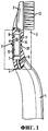
Фиг.1 - вид сбоку одного из вариантов осуществления зубной щетки согласно изобретению;Figure 1 is a side view of one embodiment of a toothbrush according to the invention;
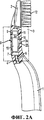
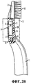
Фиг.2А и 2В - виды сбоку альтернативных вариантов осуществления изобретения;2A and 2B are side views of alternative embodiments of the invention;
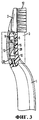
Фиг.3 - вид сбоку альтернативного варианта осуществления изобретения;Figure 3 is a side view of an alternative embodiment of the invention;
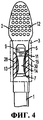
Фиг.4 - вид спереди альтернативного варианта осуществления изобретения.4 is a front view of an alternative embodiment of the invention.
Подробное описание изобретенияDETAILED DESCRIPTION OF THE INVENTION
Вибрирующая зубная щетка (Фиг.1-4) содержит, в общем, рукоятку 1, чистящую головку 2, как правило, снабженную чистящими элементами 12, и шейку 3, расположенную между головкой 2 и рукояткой 1. Хотя на чертеже проиллюстрирована чистящая головка 2, снабженная щетинками 12, можно использовать и другие чистящие элементы различных размеров, форм поперечного сечения, из различных материалов и т.д., например резиновые элементы, эластомерные элементы, полирующие элементы, абразивные элементы, чистящие элементы типа зубной нити и т.п. Головку 2 и шейку 3 обычно изготавливают из относительно жесткого материала, такого как полипропилен (РР), хотя можно использовать и другие материалы. Однако материал головки и шейки также должен быть достаточно упругим, чтобы в процессе эксплуатации шейка и головка могли вибрировать.The vibrating toothbrush (FIGS. 1-4) generally comprises a
Шейка 3 содержит механический вибратор 5, который предпочтительно включает в себя двигатель 10 и вибрационный элемент, такой как эксцентричный груз 9, присоединенный к двигателю посредством вала 11. Вибратор 5 может быть присоединен известным в данной области техники способом к источнику энергии, такому как источник электропитания (например, батарея или несколько батарей (не показаны на чертеже)), размещенному в рукоятке 1, посредством электрических соединений 8, предусмотренных в шейке 3, и приводится в действие выключателем (не показанным на чертеже). В качестве альтернативы источник энергии может находиться снаружи зубной щетки, например, это может быть источник постоянного тока, питающийся от стенной розетки. Кроме того, шейка 3 может быть изготовлена как одно целое с головкой 2 и рукояткой 1, например, литьем под давлением или другим способом, или отдельно от рукоятки 1 (не показано на чертеже) - предпочтительно на участке 4.The neck 3 comprises a
Механический вибратор 5 создает вибрацию в головке 2 посредством вращения эксцентричного груза 9 на валу 11. Двигатель 10 и эксцентричный груз 9 предпочтительно размещены в корпусе 15, предпочтительно расположенном в шейке 3 вблизи головки 2. Вибрация происходит вблизи эксцентричного груза 9, расположенного ближе к головке 2, чем двигатель 10, который расположен ближе к рукоятке 1, чем к головке 2. Как было упомянуто выше, шейку 3 предпочтительно изготавливают из упругого материала, способствующего передаче вибрации от груза 9 к головке 2. Конечно, механический вибратор 5 может быть расположен в области, не примыкающей к головке 2, при условии наличия средства передачи создаваемой вибрации к головке 2.The
С целью снижения передачи вибрации вниз от эксцентричного груза 9 или к рукоятке 1 конструкция шейки изменена вблизи эксцентричного груза 9 или под ним, чтобы дополнительно способствовать изоляции вибрации в головке 2. Согласно варианту осуществления, представленному на Фиг.1, поперечное сечение шейки 3 уменьшено вдоль наружного участка 20, чтобы уменьшить количество материала шейки под эксцентричным грузом 9, что, в свою очередь, уменьшает способность материала шейки передавать вибрации в рукоятку 1, а это, в свою очередь, способствует изоляции основной части вибраций в головке 2. Конструктивная опора для утонченного участка 20 шейки обеспечена корпусом 15 механического вибратора 5. Другими словами, корпус 15 укрепляет шейку 3 вдоль утонченного участка 20. Результатом наличия утонченного участка 20 шейки является заметное усиление вибрации головки и сведение к минимуму передачи вибраций в рукоятку 1, и все это - без потери конструктивной прочности шейки вдоль утонченного участка 20. В данном варианте осуществления предпочтительно расположить утонченный участок 20 между грузом 9 и основанием 7 двигателя 10, а еще более предпочтительно - вдоль корпуса 15, при этом двигатель 10 и/или корпус 15 будут обеспечивать конструктивную опору для уменьшенного поперечного сечения шейки.In order to reduce the transmission of vibration downward from the
На Фиг.2А проиллюстрирован альтернативный вариант осуществления изобретения, в котором из внутреннего участка 22 шейки 3 удален материал с целью создания одной или более пустот. Внутренний участок 22 не виден снаружи, так как наружная стенка 24 шейки выглядит нетронутой. Хотя является предпочтительным, чтобы внутренний участок 22 существовал в виде свободного пространства с наибольшей амортизирующей способностью, при необходимости его можно заполнить амортизирующим материалом. Механический вибратор 5 и/или корпус 15 обеспечивают конструктивную опору для шейки 3 в области внутреннего участка 22.FIG. 2A illustrates an alternative embodiment of the invention in which material is removed from the
На Фиг.2В проиллюстрирован альтернативный вариант осуществления, в котором материал шейки извлечен из наружного участка 22 шейки 3 для создания одной или более пустот. Данный наружный участок может продолжаться между корпусом 15 и наружной стенкой шейки 3. Хотя является предпочтительным, чтобы наружный участок 26 существовал в виде свободного пространства с наибольшей амортизирующей способностью, его также можно при необходимости заполнить амортизирующим материалом. В вариантах осуществления, представленных на Фиг.1-2В, величина поперечного сечения шейки уменьшена посредством участков 20, 22 и 26 предпочтительно на 5-90%, а еще более предпочтительно - на 10-50%. Это влечет за собой значительное снижение передачи вибрации к рукоятке, а также значительное усиления изоляции вибрации в головке.2B illustrates an alternative embodiment in which the neck material is removed from the
Согласно Фиг.3 и 4 вдоль боковых сторон шейки 3 создано одно (Фиг.3) или более (Фиг.4) свободных пространств (пустот) 28, 30, предпочтительно, хотя и не обязательно, заполненных амортизирующим материалом 13. Способность амортизирующего материала 13 к передаче вибрации меньше, чем у исходного материала шейки. Например, сама шейка может быть выполнена из полипропилена, а одна или более пустот, получаемых путем удаления части полипропилена из шейки, могут быть заполнены термопластическим эластомером (TPE). И вновь механический вибратор 5 и/или корпус 15 обеспечивают конструктивную опору для шейки 3 вокруг свободных пространств 28, 30.According to FIGS. 3 and 4 along the lateral sides of the neck 3, one (FIG. 3) or more (FIG. 4) free spaces (voids) 28, 30 are created, preferably, although not necessarily, filled with
Согласно, например, варианту осуществления, представленному на Фиг.3, задняя сторона стенки шейки может быть покрыта амортизирующим материалом, таким как TPE, вдоль всей области 30 шейки, при этом боковые стороны и передняя сторона выполнены из полипропилена. В этом случае TPE обеспечивает преимущество в гашении вибрации благодаря свойствам данного материала, но его протяженность дальше границ механического вибратора 5 и/или корпуса 15 не дает виброизоляции. Вместо этого дополнительные участки 28 шейки, из которых удален полипропилен, оставленные пустыми или заполненные TPE, изолируют вибрации, порождаемые вибратором 5, в головке 2 и дополнительно снижают передачу вибраций в рукоятку 1. Если эти дополнительные участки 28 шейки заполнить TPE, то они образуют передние выступы слоя амортизационного материала 13 на задней стенке шейки, что является предпочтительным.According to, for example, the embodiment of FIG. 3, the back side of the neck wall may be coated with shock absorbing material, such as TPE, along the
Согласно варианту осуществления, представленному на Фиг.4, по обеим сторонам шейки 3 обеспечены свободные пространства 28, 30, расположенные ниже груза 9 и предпочтительно заполненные материалом 13, способность которого передавать вибрацию ниже, чем у исходного материала шейки. Между участками 28, 30 образована перемычка 14 из исходного материала шейки, конструктивно соединяющая головку 2 с рукояткой 1. И вновь механический вибратор 5 и/или корпус 15 обеспечивают конструктивную опору для шейки 3 вокруг свободных пространств 28, 30.According to the embodiment of FIG. 4,
Claims (32)
Applications Claiming Priority (2)
| Application Number | Priority Date | Filing Date | Title |
|---|---|---|---|
| US70247405P | 2005-07-26 | 2005-07-26 | |
| US60/702,474 | 2005-07-26 |
Publications (2)
| Publication Number | Publication Date |
|---|---|
| RU2008106875A RU2008106875A (en) | 2009-09-10 |
| RU2372049C1 true RU2372049C1 (en) | 2009-11-10 |
Family
ID=37401248
Family Applications (1)
| Application Number | Title | Priority Date | Filing Date |
|---|---|---|---|
| RU2008106875/14A RU2372049C1 (en) | 2005-07-26 | 2006-07-25 | Vibrating toothbrush |
Country Status (13)
| Country | Link |
|---|---|
| US (7) | US7886393B2 (en) |
| EP (1) | EP1906866A1 (en) |
| KR (1) | KR100979824B1 (en) |
| CN (2) | CN101227873B (en) |
| AU (1) | AU2006272591B2 (en) |
| BR (1) | BRPI0614161A2 (en) |
| CA (1) | CA2616367C (en) |
| IN (1) | IN2014DN03338A (en) |
| MX (1) | MX2008001117A (en) |
| MY (1) | MY165931A (en) |
| RU (1) | RU2372049C1 (en) |
| TW (1) | TWI374025B (en) |
| WO (1) | WO2007014232A1 (en) |
Cited By (1)
| Publication number | Priority date | Publication date | Assignee | Title |
|---|---|---|---|---|
| RU2497482C1 (en) * | 2009-12-25 | 2013-11-10 | Панасоник Корпорэйшн | Electric toothbrush |
Families Citing this family (21)
| Publication number | Priority date | Publication date | Assignee | Title |
|---|---|---|---|---|
| US8327858B2 (en) * | 2004-08-11 | 2012-12-11 | Elc Management Llc | Vibrating mascara applicator |
| US8317423B2 (en) | 2004-08-11 | 2012-11-27 | Elc Management Llc | Mascara for use with a vibrating applicator: compositions and methods |
| US7465114B2 (en) * | 2004-08-11 | 2008-12-16 | Elc Management Llc | Vibrating mascara applicator, suitable compositions and method of use |
| NO327027B1 (en) * | 2007-04-23 | 2009-04-06 | Petosan As | Electric toothbrush |
| AU2009235384A1 (en) * | 2008-04-10 | 2009-10-15 | Vilain Marcel Et Fils | Vibrating brush |
| US8453285B2 (en) | 2009-07-16 | 2013-06-04 | Brushpoint Innovations Inc | Vibrating toothbrush and a replaceable brush head for use with the same |
| JP5547468B2 (en) * | 2009-12-25 | 2014-07-16 | パナソニック株式会社 | electric toothbrush |
| US8764688B1 (en) * | 2010-04-30 | 2014-07-01 | Purdue Research Foundation | Therapeutic method and apparatus using mechanically induced vibration |
| KR20140046025A (en) | 2011-07-12 | 2014-04-17 | 콜게이트-파아므올리브캄파니 | Vibratory and oscillatory toothbrush and refill head for the same |
| CN104720913B (en) | 2013-12-19 | 2017-07-18 | 高露洁-棕榄公司 | Electric toothbrush |
| US10849727B2 (en) | 2015-01-09 | 2020-12-01 | Church & Dwight Co., Inc. | Electric toothbrush |
| EP4245184A3 (en) * | 2015-06-12 | 2023-10-25 | Colgate-Palmolive Company | Electric toothbrush and brush unit |
| US20170215573A1 (en) * | 2016-01-29 | 2017-08-03 | Mercury Innovations Limited | Oral hygiene device |
| KR101788694B1 (en) | 2016-10-26 | 2017-11-15 | (주)원스타인터내셔널 | Sonic vibration toothbrush |
| CN108852545A (en) * | 2017-05-12 | 2018-11-23 | 张雨同 | A kind of ultrasonic cavitron of not damage tooth |
| CN109077438A (en) * | 2017-06-13 | 2018-12-25 | 深圳市东上力达科技有限公司 | Electric toothbrush head swinging structure |
| CN110623764B (en) * | 2018-06-25 | 2021-12-10 | 陈义聪 | Three-in-one tooth cleaning rod with toothpick, interdental brush and dental floss rod structure |
| US10952921B1 (en) | 2018-07-03 | 2021-03-23 | Vibration Cane, LLC | Massage device |
| US11596508B2 (en) | 2019-03-08 | 2023-03-07 | Church & Dwight Co., Inc. | Electric toothbrush and a brush head for the same |
| US10786339B1 (en) | 2019-07-12 | 2020-09-29 | Sdc U.S. Smilepay Spv | Hygienic brush |
| RU2733248C1 (en) * | 2020-03-13 | 2020-09-30 | Орлан Дулушович Ондар | Electric toothbrush |
Family Cites Families (15)
| Publication number | Priority date | Publication date | Assignee | Title |
|---|---|---|---|---|
| JP2714462B2 (en) * | 1989-08-19 | 1998-02-16 | 松下電工株式会社 | Vibrating razor |
| JPH03261407A (en) * | 1990-03-09 | 1991-11-21 | Hiroshi Fukuba | Vibration toothbrush |
| JPH08117258A (en) * | 1994-10-24 | 1996-05-14 | Purakon:Kk | Electric toothbrush |
| JPH08126786A (en) * | 1994-10-31 | 1996-05-21 | Sanyo Electric Co Ltd | Portable electric apparatus containing motor |
| DE19654319C1 (en) * | 1996-12-24 | 1998-08-06 | Rowenta Werke Gmbh | Electric toothbrush |
| CN1739464B (en) * | 1999-10-19 | 2013-06-19 | 特里沙控股公司 | Toothbrush with vibrating head part |
| RU2174381C2 (en) | 1999-11-19 | 2001-10-10 | Чернов Евгений Иванович | Toothbrush |
| FI20000760A0 (en) * | 2000-03-31 | 2000-03-31 | Nokia Corp | Authentication in a packet data network |
| US6421865B1 (en) * | 2000-10-25 | 2002-07-23 | Mcdougall Gregory John | Electric toothbrush |
| US6421866B1 (en) * | 2000-12-19 | 2002-07-23 | Mcdougall Gregory John | Electric toothbrush |
| US6920659B2 (en) * | 2001-01-12 | 2005-07-26 | Water Pik, Inc. | Toothbrush |
| WO2003037210A1 (en) * | 2001-10-30 | 2003-05-08 | Dworzan William S | Toothbrush with vibrating head |
| CA2498868A1 (en) | 2002-09-20 | 2004-04-01 | Colgate-Palmolive Company | Power toothbrush |
| DE10245086A1 (en) | 2002-09-27 | 2004-04-08 | Trisa Holding Ag | Method of making a toothbrush |
| DE10352993A1 (en) * | 2003-11-13 | 2005-06-16 | Braun Gmbh | Brush part for an electric toothbrush |
-
2006
- 2006-07-24 TW TW095126957A patent/TWI374025B/en not_active IP Right Cessation
- 2006-07-24 MY MYPI20063518A patent/MY165931A/en unknown
- 2006-07-25 EP EP06788487A patent/EP1906866A1/en not_active Withdrawn
- 2006-07-25 CN CN2006800272122A patent/CN101227873B/en not_active Expired - Fee Related
- 2006-07-25 RU RU2008106875/14A patent/RU2372049C1/en not_active IP Right Cessation
- 2006-07-25 KR KR1020087003845A patent/KR100979824B1/en not_active IP Right Cessation
- 2006-07-25 WO PCT/US2006/028919 patent/WO2007014232A1/en active Application Filing
- 2006-07-25 MX MX2008001117A patent/MX2008001117A/en active IP Right Grant
- 2006-07-25 CN CN201310489444.1A patent/CN103784208B/en not_active Expired - Fee Related
- 2006-07-25 AU AU2006272591A patent/AU2006272591B2/en not_active Ceased
- 2006-07-25 BR BRPI0614161-7A patent/BRPI0614161A2/en not_active IP Right Cessation
- 2006-07-25 CA CA2616367A patent/CA2616367C/en not_active Expired - Fee Related
- 2006-07-26 US US11/460,158 patent/US7886393B2/en active Active
-
2011
- 2011-01-11 US US13/004,565 patent/US8327489B2/en active Active
-
2012
- 2012-12-05 US US13/706,282 patent/US8739344B2/en not_active Expired - Fee Related
-
2014
- 2014-04-25 IN IN3338DEN2014 patent/IN2014DN03338A/en unknown
- 2014-05-29 US US14/289,801 patent/US9649181B2/en active Active
-
2017
- 2017-04-06 US US15/481,229 patent/US10004581B2/en not_active Expired - Fee Related
-
2018
- 2018-05-24 US US15/988,590 patent/US10390918B2/en active Active
-
2019
- 2019-07-16 US US16/512,789 patent/US11051921B2/en active Active
Cited By (1)
| Publication number | Priority date | Publication date | Assignee | Title |
|---|---|---|---|---|
| RU2497482C1 (en) * | 2009-12-25 | 2013-11-10 | Панасоник Корпорэйшн | Electric toothbrush |
Also Published As
Similar Documents
| Publication | Publication Date | Title |
|---|---|---|
| RU2372049C1 (en) | Vibrating toothbrush | |
| EP3136924B1 (en) | Powered skin care device | |
| KR20160148632A (en) | Powered skin care device | |
| EP3136922B1 (en) | Powered skin care device | |
| KR100604484B1 (en) | Non-contact type ultrasonic oral washing device using piezoeceramic | |
| KR200326602Y1 (en) | A Vibration Tooth Brush For Utrasonic Generator | |
| KR200407528Y1 (en) | Shock Tooth Vibration Toothbrush | |
| US20090083918A1 (en) | Hair brush | |
| KR20090117768A (en) | Hair brush | |
| CN108392288A (en) | Electric toothbrush head with protective device and electric toothbrush | |
| CA1314159C (en) | Dental hygiene device | |
| CN116035749A (en) | Electric toothbrush shock-absorbing structure and electric toothbrush | |
| WO2009065746A1 (en) | Hair grooming device |
Legal Events
| Date | Code | Title | Description |
|---|---|---|---|
| MM4A | The patent is invalid due to non-payment of fees |
Effective date: 20170726 |