RU2364862C2 - Gas chromatograph - Google Patents
Gas chromatograph Download PDFInfo
- Publication number
- RU2364862C2 RU2364862C2 RU2006125218/28A RU2006125218A RU2364862C2 RU 2364862 C2 RU2364862 C2 RU 2364862C2 RU 2006125218/28 A RU2006125218/28 A RU 2006125218/28A RU 2006125218 A RU2006125218 A RU 2006125218A RU 2364862 C2 RU2364862 C2 RU 2364862C2
- Authority
- RU
- Russia
- Prior art keywords
- gas chromatograph
- chromatograph according
- column
- sample
- capillaries
- Prior art date
Links
- 229920005597 polymer membrane Polymers 0.000 claims abstract description 5
- 239000007789 gas Substances 0.000 claims description 57
- 239000012528 membrane Substances 0.000 claims description 15
- 238000010438 heat treatment Methods 0.000 claims description 13
- 229920000642 polymer Polymers 0.000 claims description 7
- 239000011810 insulating material Substances 0.000 claims description 3
- 238000005086 pumping Methods 0.000 claims description 2
- 239000004065 semiconductor Substances 0.000 claims description 2
- 238000001035 drying Methods 0.000 claims 1
- 239000000126 substance Substances 0.000 abstract description 44
- 238000000926 separation method Methods 0.000 abstract description 21
- 238000001514 detection method Methods 0.000 abstract description 8
- 238000004458 analytical method Methods 0.000 abstract description 6
- 238000005259 measurement Methods 0.000 abstract description 2
- 230000000694 effects Effects 0.000 abstract 1
- 239000000523 sample Substances 0.000 description 30
- 238000004817 gas chromatography Methods 0.000 description 23
- 239000012510 hollow fiber Substances 0.000 description 22
- 239000003570 air Substances 0.000 description 12
- 238000000034 method Methods 0.000 description 12
- 210000001601 blood-air barrier Anatomy 0.000 description 8
- 239000000463 material Substances 0.000 description 8
- OSWPMRLSEDHDFF-UHFFFAOYSA-N methyl salicylate Chemical compound COC(=O)C1=CC=CC=C1O OSWPMRLSEDHDFF-UHFFFAOYSA-N 0.000 description 8
- 239000012530 fluid Substances 0.000 description 7
- 230000014759 maintenance of location Effects 0.000 description 6
- 230000035945 sensitivity Effects 0.000 description 6
- VYPSYNLAJGMNEJ-UHFFFAOYSA-N Silicium dioxide Chemical compound O=[Si]=O VYPSYNLAJGMNEJ-UHFFFAOYSA-N 0.000 description 5
- 239000000835 fiber Substances 0.000 description 5
- 230000006872 improvement Effects 0.000 description 5
- 150000002500 ions Chemical class 0.000 description 5
- 239000012071 phase Substances 0.000 description 5
- 230000008569 process Effects 0.000 description 5
- 230000008901 benefit Effects 0.000 description 4
- 239000012159 carrier gas Substances 0.000 description 4
- 238000013461 design Methods 0.000 description 4
- 238000005265 energy consumption Methods 0.000 description 4
- 229960001047 methyl salicylate Drugs 0.000 description 4
- 239000000203 mixture Substances 0.000 description 4
- 238000002360 preparation method Methods 0.000 description 4
- 230000005526 G1 to G0 transition Effects 0.000 description 3
- PEDCQBHIVMGVHV-UHFFFAOYSA-N Glycerine Chemical compound OCC(O)CO PEDCQBHIVMGVHV-UHFFFAOYSA-N 0.000 description 3
- 238000004587 chromatography analysis Methods 0.000 description 3
- 239000010408 film Substances 0.000 description 3
- 238000001914 filtration Methods 0.000 description 3
- -1 for example Polymers 0.000 description 3
- 239000005350 fused silica glass Substances 0.000 description 3
- 238000004519 manufacturing process Methods 0.000 description 3
- 238000005070 sampling Methods 0.000 description 3
- PXHVJJICTQNCMI-UHFFFAOYSA-N Nickel Chemical compound [Ni] PXHVJJICTQNCMI-UHFFFAOYSA-N 0.000 description 2
- 239000004952 Polyamide Substances 0.000 description 2
- 238000013459 approach Methods 0.000 description 2
- 230000005540 biological transmission Effects 0.000 description 2
- 150000001875 compounds Chemical class 0.000 description 2
- 238000000502 dialysis Methods 0.000 description 2
- 238000009826 distribution Methods 0.000 description 2
- 238000011049 filling Methods 0.000 description 2
- 239000011521 glass Substances 0.000 description 2
- 239000007788 liquid Substances 0.000 description 2
- 239000007791 liquid phase Substances 0.000 description 2
- 229920002647 polyamide Polymers 0.000 description 2
- 229920001296 polysiloxane Polymers 0.000 description 2
- 238000012545 processing Methods 0.000 description 2
- 230000004044 response Effects 0.000 description 2
- 150000003384 small molecules Chemical class 0.000 description 2
- 239000007787 solid Substances 0.000 description 2
- 238000012546 transfer Methods 0.000 description 2
- XLYOFNOQVPJJNP-UHFFFAOYSA-N water Substances O XLYOFNOQVPJJNP-UHFFFAOYSA-N 0.000 description 2
- QDWLBCPOTMKDHK-UHFFFAOYSA-N 2-[4-(trifluoromethyl)pyridin-3-yl]ethanamine Chemical compound NCCC1=CN=CC=C1C(F)(F)F QDWLBCPOTMKDHK-UHFFFAOYSA-N 0.000 description 1
- 239000005909 Kieselgur Substances 0.000 description 1
- 239000004642 Polyimide Substances 0.000 description 1
- XUIMIQQOPSSXEZ-UHFFFAOYSA-N Silicon Chemical compound [Si] XUIMIQQOPSSXEZ-UHFFFAOYSA-N 0.000 description 1
- 238000010521 absorption reaction Methods 0.000 description 1
- 239000012080 ambient air Substances 0.000 description 1
- 239000012491 analyte Substances 0.000 description 1
- 230000015572 biosynthetic process Effects 0.000 description 1
- 229920002301 cellulose acetate Polymers 0.000 description 1
- 239000003795 chemical substances by application Substances 0.000 description 1
- 239000002575 chemical warfare agent Substances 0.000 description 1
- 238000013375 chromatographic separation Methods 0.000 description 1
- 238000000576 coating method Methods 0.000 description 1
- 238000001816 cooling Methods 0.000 description 1
- 230000018044 dehydration Effects 0.000 description 1
- 238000006297 dehydration reaction Methods 0.000 description 1
- 230000001934 delay Effects 0.000 description 1
- 230000002542 deteriorative effect Effects 0.000 description 1
- 238000011161 development Methods 0.000 description 1
- 238000004090 dissolution Methods 0.000 description 1
- 238000005516 engineering process Methods 0.000 description 1
- 230000005183 environmental health Effects 0.000 description 1
- 229920006332 epoxy adhesive Polymers 0.000 description 1
- 238000000605 extraction Methods 0.000 description 1
- 230000004907 flux Effects 0.000 description 1
- 238000005194 fractionation Methods 0.000 description 1
- 238000005342 ion exchange Methods 0.000 description 1
- 238000001871 ion mobility spectroscopy Methods 0.000 description 1
- 230000007774 longterm Effects 0.000 description 1
- 229910044991 metal oxide Inorganic materials 0.000 description 1
- 150000004706 metal oxides Chemical class 0.000 description 1
- 238000012986 modification Methods 0.000 description 1
- 230000004048 modification Effects 0.000 description 1
- 238000012544 monitoring process Methods 0.000 description 1
- 229910052759 nickel Inorganic materials 0.000 description 1
- 239000002245 particle Substances 0.000 description 1
- 230000002093 peripheral effect Effects 0.000 description 1
- 230000035699 permeability Effects 0.000 description 1
- 238000005191 phase separation Methods 0.000 description 1
- 231100000614 poison Toxicity 0.000 description 1
- 229920002492 poly(sulfone) Polymers 0.000 description 1
- 229920000728 polyester Polymers 0.000 description 1
- 229920001721 polyimide Polymers 0.000 description 1
- 229920000098 polyolefin Polymers 0.000 description 1
- 239000011148 porous material Substances 0.000 description 1
- 239000000843 powder Substances 0.000 description 1
- 238000004886 process control Methods 0.000 description 1
- 239000010453 quartz Substances 0.000 description 1
- 239000013074 reference sample Substances 0.000 description 1
- 238000011160 research Methods 0.000 description 1
- 229910052710 silicon Inorganic materials 0.000 description 1
- 239000010703 silicon Substances 0.000 description 1
- 239000007790 solid phase Substances 0.000 description 1
- 239000002594 sorbent Substances 0.000 description 1
- 238000002336 sorption--desorption measurement Methods 0.000 description 1
- 230000006641 stabilisation Effects 0.000 description 1
- 238000011105 stabilization Methods 0.000 description 1
- 229910001220 stainless steel Inorganic materials 0.000 description 1
- 239000010935 stainless steel Substances 0.000 description 1
- 239000000758 substrate Substances 0.000 description 1
- 238000010897 surface acoustic wave method Methods 0.000 description 1
- 239000012209 synthetic fiber Substances 0.000 description 1
- 229920002994 synthetic fiber Polymers 0.000 description 1
- 239000013076 target substance Substances 0.000 description 1
- 230000002277 temperature effect Effects 0.000 description 1
- 238000012360 testing method Methods 0.000 description 1
- 239000010409 thin film Substances 0.000 description 1
- 231100000331 toxic Toxicity 0.000 description 1
- 230000002588 toxic effect Effects 0.000 description 1
- 239000003440 toxic substance Substances 0.000 description 1
- 235000012431 wafers Nutrition 0.000 description 1
Images

Classifications
-
- G—PHYSICS
- G01—MEASURING; TESTING
- G01N—INVESTIGATING OR ANALYSING MATERIALS BY DETERMINING THEIR CHEMICAL OR PHYSICAL PROPERTIES
- G01N30/00—Investigating or analysing materials by separation into components using adsorption, absorption or similar phenomena or using ion-exchange, e.g. chromatography or field flow fractionation
- G01N30/02—Column chromatography
- G01N30/60—Construction of the column
- G01N30/6052—Construction of the column body
- G01N30/6073—Construction of the column body in open tubular form
-
- B—PERFORMING OPERATIONS; TRANSPORTING
- B01—PHYSICAL OR CHEMICAL PROCESSES OR APPARATUS IN GENERAL
- B01D—SEPARATION
- B01D53/00—Separation of gases or vapours; Recovering vapours of volatile solvents from gases; Chemical or biological purification of waste gases, e.g. engine exhaust gases, smoke, fumes, flue gases, aerosols
- B01D53/02—Separation of gases or vapours; Recovering vapours of volatile solvents from gases; Chemical or biological purification of waste gases, e.g. engine exhaust gases, smoke, fumes, flue gases, aerosols by adsorption, e.g. preparative gas chromatography
-
- B—PERFORMING OPERATIONS; TRANSPORTING
- B01—PHYSICAL OR CHEMICAL PROCESSES OR APPARATUS IN GENERAL
- B01D—SEPARATION
- B01D61/00—Processes of separation using semi-permeable membranes, e.g. dialysis, osmosis or ultrafiltration; Apparatus, accessories or auxiliary operations specially adapted therefor
-
- B—PERFORMING OPERATIONS; TRANSPORTING
- B01—PHYSICAL OR CHEMICAL PROCESSES OR APPARATUS IN GENERAL
- B01D—SEPARATION
- B01D63/00—Apparatus in general for separation processes using semi-permeable membranes
- B01D63/02—Hollow fibre modules
-
- B—PERFORMING OPERATIONS; TRANSPORTING
- B01—PHYSICAL OR CHEMICAL PROCESSES OR APPARATUS IN GENERAL
- B01D—SEPARATION
- B01D63/00—Apparatus in general for separation processes using semi-permeable membranes
- B01D63/02—Hollow fibre modules
- B01D63/031—Two or more types of hollow fibres within one bundle or within one potting or tube-sheet
-
- B—PERFORMING OPERATIONS; TRANSPORTING
- B01—PHYSICAL OR CHEMICAL PROCESSES OR APPARATUS IN GENERAL
- B01D—SEPARATION
- B01D2313/00—Details relating to membrane modules or apparatus
- B01D2313/22—Cooling or heating elements
-
- B—PERFORMING OPERATIONS; TRANSPORTING
- B01—PHYSICAL OR CHEMICAL PROCESSES OR APPARATUS IN GENERAL
- B01D—SEPARATION
- B01D2313/00—Details relating to membrane modules or apparatus
- B01D2313/22—Cooling or heating elements
- B01D2313/221—Heat exchangers
-
- G—PHYSICS
- G01—MEASURING; TESTING
- G01N—INVESTIGATING OR ANALYSING MATERIALS BY DETERMINING THEIR CHEMICAL OR PHYSICAL PROPERTIES
- G01N30/00—Investigating or analysing materials by separation into components using adsorption, absorption or similar phenomena or using ion-exchange, e.g. chromatography or field flow fractionation
- G01N2030/0095—Separation specially adapted for use outside laboratory, e.g. field sampling, portable equipments
-
- G—PHYSICS
- G01—MEASURING; TESTING
- G01N—INVESTIGATING OR ANALYSING MATERIALS BY DETERMINING THEIR CHEMICAL OR PHYSICAL PROPERTIES
- G01N30/00—Investigating or analysing materials by separation into components using adsorption, absorption or similar phenomena or using ion-exchange, e.g. chromatography or field flow fractionation
- G01N30/02—Column chromatography
- G01N30/60—Construction of the column
- G01N30/6034—Construction of the column joining multiple columns
- G01N30/6043—Construction of the column joining multiple columns in parallel
-
- G—PHYSICS
- G01—MEASURING; TESTING
- G01N—INVESTIGATING OR ANALYSING MATERIALS BY DETERMINING THEIR CHEMICAL OR PHYSICAL PROPERTIES
- G01N30/00—Investigating or analysing materials by separation into components using adsorption, absorption or similar phenomena or using ion-exchange, e.g. chromatography or field flow fractionation
- G01N30/02—Column chromatography
- G01N30/60—Construction of the column
- G01N30/6052—Construction of the column body
- G01N30/6069—Construction of the column body with compartments or bed substructure
Abstract
Description
Область техники, к которой относится изобретениеFIELD OF THE INVENTION
Настоящее изобретение относится к хроматографу, предназначенному для анализа газообразного образца. Хроматограф имеет подающую систему для подачи образца, открытую трубчатую капиллярную колонку, разделяющую компоненты образца, устройство контроля температуры для регулирования температуры колонки и детектор для детектирования разделенных компонентов образца, причем указанная колонка содержит пучок открытых трубчатых капилляров.The present invention relates to a chromatograph for analyzing a gaseous sample. The chromatograph has a feeding system for feeding the sample, an open tubular capillary column separating the components of the sample, a temperature control device for controlling the temperature of the column, and a detector for detecting the separated components of the sample, said column containing a bunch of open tubular capillaries.
Уровень техникиState of the art
Химическое состояние образцов в виде газовой фазы формируется испаренными или газообразными химическими веществами, перемешанными в окружающей среде, обычно в воздухе. Такой средой могут быть также технологические газы или вакуум. Для обнаружения и идентификации конкретных химических веществ, находящихся в определенной окружающей среде, применяют детектор.The chemical state of the samples in the form of a gas phase is formed by vaporized or gaseous chemicals mixed in the environment, usually in air. Such a medium may also be process gases or vacuum. A detector is used to detect and identify specific chemicals in a specific environment.
Главной характеристикой химического детектора является его способность преобразовывать химическое состояние в электрический сигнал и передавать этот сигнал для дальнейшей обработки. В типичном случае назначение детектора сводится к проведению как качественного, так и количественного определения конкретных химических веществ, находящихся в определенной окружающей среде. В этом случае возникает техническая проблема, связанная с тем, что выходной сигнал детектора не абсолютно специфичен, т.е. обладает чувствительностью также и к другим химическим веществам, которые не являются предметом исследования. Указанное свойство часто обозначают термином "перекрестная чувствительность", причем обычно оно приводит к ложной идентификации целевого вещества.The main characteristic of a chemical detector is its ability to convert a chemical state into an electrical signal and transmit this signal for further processing. In a typical case, the purpose of the detector is to conduct both qualitative and quantitative determination of specific chemicals in a particular environment. In this case, a technical problem arises related to the fact that the output signal of the detector is not absolutely specific, i.e. also sensitive to other chemicals that are not the subject of research. This property is often referred to by the term “cross sensitivity”, and usually it leads to a false identification of the target substance.
Существуют два основных направления решения проблемы перекрестной чувствительности химических детекторов: (i) разработка более специфичных датчиков (под датчиком подразумевается первая часть измерительной цепочки, конвертирующей входной переменный параметр в пригодный для измерения сигнал) или (ii) проведение химического разделения до детектирования. Во втором случае, как правило, применяют хроматографические методики, фильтрацию, регулируемые методики адсорбции-десорбции, а также специальные процедуры приготовления образца, в том числе растворение, разделение фаз, экстракцию, химическое получение производных соединений и ионный обмен. В варианте детектирования химического состояния, имеющего вид газовой фазы (особенно при выделении небольших составляющих в окружающем воздухе портативным детектором), этапы приготовления образца усложняются, поскольку их трудно автоматизировать, сделать более мобильными и менее затратными по времени. Таким образом, для быстрого мониторинга в реальном времени они не пригодны.There are two main directions for solving the cross-sensitivity problem of chemical detectors: (i) development of more specific sensors (a sensor means the first part of the measuring chain that converts the input variable into a signal suitable for measurement) or (ii) chemical separation prior to detection. In the second case, as a rule, chromatographic techniques, filtration, controlled adsorption-desorption techniques, as well as special sample preparation procedures, including dissolution, phase separation, extraction, chemical preparation of derivatives and ion exchange, are used. In the variant of detecting a chemical state in the form of a gas phase (especially when small components are separated in a portable detector by air), the sample preparation steps are complicated because they are difficult to automate, make them more mobile and less time consuming. Thus, they are not suitable for quick real-time monitoring.
Из остальных перечисленных возможных подходов к проведению химического разделения хорошо известной методикой аналитической химии является хроматография. Газовая хроматография (ГХ) представляет собой предпочтительный способ разделения стабильных и летучих соединений, а также образцов, находящихся в газовой фазе. В рамках указанного метода осуществляют химическое разделение посредством фракционирования компонентов смеси на мобильную газовую фазу и стационарную твердую или жидкую фазу, удерживаемую на твердой подложке. В стационарной хроматографической системе время удерживания исследуемого вещества сорбентом (т.е. время прохождения образца от входа через колонку к детектору) для конкретного анализируемого соединения является постоянной величиной, т.е. этот параметр можно использовать для идентификации такого соединения. Таким образом, хотя хроматография, в первую очередь, представляет собой технологию разделения, с ее помощью можно идентифицировать разделенные соединения сложного образца по значениям их времени удерживания. Процесс проводят в ГХ приборе, состоящем обычно из системы подачи образца, газа-носителя и блока (блоков) регулировки потока указанного газа, одной или нескольких колонок внутри камеры (как правило, оборудованных термостатом) и одного или нескольких химических детекторов.Of the remaining listed possible approaches to conducting chemical separation, chromatography is a well-known method of analytical chemistry. Gas chromatography (GC) is the preferred method for the separation of stable and volatile compounds, as well as samples in the gas phase. In the framework of this method, chemical separation is carried out by fractionation of the components of the mixture into a mobile gas phase and a stationary solid or liquid phase held on a solid substrate. In a stationary chromatographic system, the retention time of the test substance by the sorbent (i.e., the time the sample passed from the entrance through the column to the detector) for a particular analyte is constant, i.e. this parameter can be used to identify such a connection. Thus, although chromatography is primarily a separation technology, it can be used to identify separated compounds of a complex sample by their retention times. The process is carried out in a GC device, usually consisting of a sample supply system, a carrier gas and a block (blocks) for adjusting the flow of said gas, one or more columns inside the chamber (usually equipped with a thermostat), and one or more chemical detectors.
С точки зрения разделительной способности и, таким образом, разрешения, достигаемого в анализе, ключевым техническим компонентом ГХ является колонка. Колонки можно разделить на два основных типа: (i) насадочная (набивная) колонка и (ii) полая (открытая) трубчатая, или так называемая капиллярная колонка. Набивную колонку конструируют из трубы, изготовленной, например, из нержавеющей стали, никеля или стекла, причем ее внутренний диаметр обычно находится в интервале 1-10 мм. Колонки заполняют инертным удерживающим порошком. Обычно это диатомитовая земля со средним внутренним диаметром пор 1-10 мкм и размером частиц 100-200 мкм. Колонка второго типа, т.е. открытая трубчатая капиллярная колонка, имеет малый внутренний диаметр 10-1000 мкм. Ее обычно конструируют из плавленого кварца (стекло очень высокой чистоты), а наружную стенку защищают твердым и плотным полимером типа полиимида. Как правило, колонки имеют трубчатую форму с ничем не ограниченным проходом для потока в средней части колонки. Внутреннюю поверхность плавленого кварца химическим образом модифицируют покрытиями или пленками различного типа, обеспечивающими формирование так называемых неподвижных фаз. Указанные фазы имеют различную полярность и, таким образом, селективны по отношению к процессу разделения. Неподвижная фаза может представлять собой жидкий слой или тонкую пленку, обычно изготовленную из полимера, например из полисилоксана, силикона или полиамида, причем в зависимости от ситуации эти слой и пленка функционируют различным образом. На общую разделительную способность колонки влияют такие параметры пленки неподвижной фазы, как химический состав, микроструктура, строение и толщина.In terms of separation ability and thus the resolution achieved in the analysis, the column is a key technical component of the GC. Columns can be divided into two main types: (i) packed (packed) column and (ii) hollow (open) tubular, or the so-called capillary column. A packed column is constructed from a pipe made, for example, of stainless steel, nickel or glass, and its internal diameter is usually in the range of 1-10 mm. The columns are filled with an inert retention powder. Usually this is diatomaceous earth with an average inner pore diameter of 1-10 microns and a particle size of 100-200 microns. Column of the second type, i.e. open tubular capillary column, has a small inner diameter of 10-1000 microns. It is usually constructed of fused quartz (glass of very high purity), and the outer wall is protected by a solid and dense polymer such as polyimide. Typically, the columns are tubular with an unlimited flow path in the middle of the column. The inner surface of fused silica is chemically modified with coatings or films of various types, which ensure the formation of so-called stationary phases. These phases have different polarity and, thus, are selective with respect to the separation process. The stationary phase can be a liquid layer or a thin film, usually made of a polymer, for example, polysiloxane, silicone or polyamide, and depending on the situation, this layer and film function in different ways. The general separation ability of the column is affected by such parameters of the stationary phase film as chemical composition, microstructure, structure and thickness.
Из всех типов колонок в аналитической химии наиболее предпочтительной является открытая трубчатая капиллярная вследствие ее повышенной разделительной способности относительно общего времени анализа, улучшенной долговременной стабильности и более высокого качества анализа (последнее свойство определяется повышенной воспроизводимостью процесса изготовления).Of all the types of columns in analytical chemistry, open tubular capillary is most preferable due to its increased separation ability relative to the total analysis time, improved long-term stability and higher quality of analysis (the latter property is determined by the increased reproducibility of the manufacturing process).
На существующем уровне техники применение трубок с открытыми трубчатыми ГХ капиллярами в комбинации с различными портативными химическими детекторами хорошо известно. Подтверждением этому могут служить, в частности, патенты США №№5114439 и 5856616, в которых описано применение компактных по размерам ГХ колонок с низким потреблением энергии, предназначенных для портативных приложений. Кроме того, в патентном документе WO 9941601 приводится описание использования комбинации ГХ колонки с низким потреблением энергии и специфической системы отбора проб. Далее, патенты США №№4888295 и 6354160 описывают соответственно применение "приемлемой с коммерческой точки зрения" ГХ колонки в комбинации с детектором, сформированным матрицей электрохимических датчиков, и ГХ колонки, используемой совместно с детекторами на основе поверхностных акустических волн, причем функцию открытых трубчатых колонок могут выполнять колонки, сформированные на кремниевых пластинах (см. также патент США №6134944).In the state of the art, the use of tubes with open tubular GC capillaries in combination with various portable chemical detectors is well known. This can be confirmed, in particular, by US patents Nos. 5114439 and 5856616, which describe the use of compact size GC columns with low energy consumption, designed for portable applications. In addition, patent document WO 9941601 describes the use of a combination of a low energy consumption GC column and a specific sampling system. Further, US patents Nos. 4,888,295 and 6,354,160 describe respectively the use of a "commercially acceptable" GC column in combination with a detector formed by an array of electrochemical sensors and a GC column used in conjunction with surface acoustic wave detectors, the function of open tubular columns can perform columns formed on silicon wafers (see also US patent No. 6134944).
Для применения ГХ метода в портативных, причем предпочтительно ручных (т.е. удерживаемых в руках), устройствах требуется, чтобы они потребляли мало энергии, были легкими и компактными по размерам, а также обеспечивали быстрое детектирование, сохраняя в то же время высокое разрешение вследствие хорошей разделительной способности. До настоящего времени улучшение рабочих параметров портативных устройств происходило главным образом за счет применения высоких температур в колонках, а также улучшений контроля температуры и конструкции нагревающей системы. Кроме того, улучшения касались модификаций потока газа-носителя и конструкции специальных систем отбора проб и детектирования.The use of the GC method in portable, preferably hand-held (i.e., held in hands) devices requires that they consume little energy, are light and compact in size, and also provide fast detection, while maintaining high resolution due to good separation ability. To date, the improvement of the operating parameters of portable devices has been mainly due to the use of high temperatures in the columns, as well as improvements in temperature control and the design of the heating system. In addition, improvements concerned modifications to the carrier gas stream and the design of special sampling and detection systems.
Другие направления повышения пригодности ГХ метода для портативных приложений включали в себя применение укороченных колонок и колонок с уменьшенным внутренним диаметром с целью увеличения эффективности и скорости анализов. Однако эти улучшения приведут к уменьшению разделения веществ или, в альтернативной ситуации, уменьшат объем образца и существенно увеличат потребляемую энергию. В результате вследствие увеличения падения давления в колонке возрастут стоимость и размеры насоса. Недостаток применения образца с маленьким объемом заключается в том, что при этом обычно ослабляется отклик детектора и повышается чувствительность к локальным изменениям в образце. Тем самым ухудшается точность времени удерживания. Кроме того, контроль маленьких объемов текучей среды может оказаться затруднительным с технической точки зрения и дорогим.Other ways to increase the suitability of the GC method for portable applications included the use of shorter columns and columns with reduced inner diameter in order to increase the efficiency and speed of analysis. However, these improvements will lead to a decrease in the separation of substances or, in an alternative situation, will reduce the volume of the sample and significantly increase the energy consumed. As a result, due to the increase in pressure drop in the column, the cost and size of the pump will increase. The disadvantage of using a sample with a small volume is that it usually attenuates the response of the detector and increases the sensitivity to local changes in the sample. Thereby deteriorating the accuracy of the retention time. In addition, controlling small volumes of fluid can be technically difficult and expensive.
Указанные недостатки были преодолены за счет применения колонки, содержащей пучок открытых трубчатых капилляров (см., например, Baumbach J.I. et al. Int. J. Env. Anal. Chem. (1997), 66, pp.225-239; Int. J. for Ion Mobility Spectrometry (2000), 3, pp.28-37).These drawbacks were overcome by the use of a column containing a bundle of open tubular capillaries (see, for example, Baumbach JI et al. Int. J. Env. Anal. Chem. (1997), 66, pp. 225-239; Int. J . for Ion Mobility Spectrometry (2000), 3, pp. 28-37).
Такие колонки изготавливаются и продаются ограниченным числом компаний, а именно компаниями Alltech Associates Inc. (США), ChemSpace s.r.o. (Чешская Республика), Sibertech (Новосибирск, Россия). Преимущества мультикапиллярных колонок заключаются в обеспечении коротких времен удерживания и, таким образом, быстрых времен детектирования при достаточно высоком разрешении и хорошей разделительной способности. Кроме того, такие колонки сохраняют высокую эффективность в широком интервале скоростей потоков газа-носителя. В результате, по сравнению с обычными монокапиллярными колонками, они могут работать с повышенными объемами образцов, причем эти объемы легко инжектируются и детектируются.Such speakers are manufactured and sold by a limited number of companies, namely Alltech Associates Inc. (USA), ChemSpace s.r.o. (Czech Republic), Sibertech (Novosibirsk, Russia). The advantages of multicapillary columns are that they provide short retention times and, thus, fast detection times with a sufficiently high resolution and good separation ability. In addition, such columns retain high efficiency over a wide range of carrier gas flow rates. As a result, compared with conventional monocapillary columns, they can work with increased volumes of samples, and these volumes are easily injected and detected.
Таким образом, указанные свойства мультикапиллярных колонок делают их идеально пригодными для ручного портативного газового хроматографа.Thus, the indicated properties of multicapillary columns make them ideally suited for a hand-held portable gas chromatograph.
Однако, поскольку колонки такого типа обычно формируют из сотен единичных капиллярных колонок, для достаточно массивных пучков трудно получить однородное распределение температуры с низким расходом энергии, а это уменьшает точность ГХ анализа.However, since columns of this type are usually formed from hundreds of single capillary columns, it is difficult to obtain a uniform temperature distribution with low energy consumption for sufficiently massive beams, and this reduces the accuracy of GC analysis.
Несмотря на то, что по сравнению с открытой трубчатой ГХ колонкой, содержащей один канал, мультикапиллярные колонки позволяют использовать гораздо более высокую скорость потока (расход) образца (или расход потока газа-носителя) через колонку, допустимый расход газа для обычных мультикапиллярных колонок все еще остается ниже 300 мл/мин. Для некоторых типов детектора этот уровень расхода может оказаться далеко не достаточным. К таким детекторам относится, например, переносной мультисенсорный спектрометр подвижности ионов, предназначенный для детектирования газообразных химических веществ, находящихся в окружающем воздухе, и использующий принцип сквозного протекания потока (см. патентный документ WO 9416320 и публикацию Utriainen M. et al. Sens. Actuators В (2003), 93, pp.17-24).Despite the fact that, compared to an open tubular GC column containing one channel, multicapillary columns allow a much higher sample flow rate (flow rate) (or carrier gas flow rate) through the column, the allowable gas flow rate for conventional multicapillary columns is still remains below 300 ml / min. For some types of detector, this flow rate may be far from sufficient. Such detectors include, for example, a portable multisensor ion mobility spectrometer designed to detect gaseous chemicals in ambient air and using the principle of through flow (see patent document WO 9416320 and publication Utriainen M. et al. Sens. Actuators B (2003), 93, pp. 17-24).
В детекторе реализуется специальный тип спектрометра подвижности ионов (ion mobility spectrometer, IMS). Этот тип можно описать как IMS-спектрометр аспирационного конденсаторного типа или типа разомкнутого контура, скомбинированный с другими датчиками, такими как полупроводниковые газовые датчики, а также датчики температуры и влажности. Для переносных и портативных устройств химического детектирования детектор изготавливают под торговыми наименованиями ChemPro100, M90-D1-C (Environics Oy, Финляндия) и MultilMS (Drager Safety, Германия). Дополнительно охарактеризовать этот детектор можно следующим образом: он использует непрерывный сквозной поток при расходе, составляющем обычно 800-3500 мл/мин, предпочтительно 1000-2000 мл/мин, и обеспечивает таким образом хорошую статистическую достоверность семплирования, а также высокое быстродействие и быстрый возврат в исходное положение. Все перечисленные параметры имеют существенное значение, причем в особенности в том случае, когда поставленной задачей является обеспечение надежного заблаговременного предупреждения о присутствии в воздухе токсичных веществ. Характерной особенностью указанного детектора является также такая зависимость чувствительности от скорости потока, при которой более высокая скорость предпочтительна. К другим характерным особенностям детектора относится чувствительность к быстрым изменениям потока (и давления), а также к быстрым и большим изменениям влажности и температуры.The detector implements a special type of ion mobility spectrometer (IMS). This type can be described as an IMS condenser-type or open-loop type IMS spectrometer combined with other sensors, such as semiconductor gas sensors, as well as temperature and humidity sensors. For portable and portable chemical detection devices, the detector is manufactured under the trade names ChemPro100, M90-D1-C (Environics Oy, Finland) and MultilMS (Drager Safety, Germany). Additionally, this detector can be characterized as follows: it uses a continuous through flow at a flow rate of usually 800-3500 ml / min, preferably 1000-2000 ml / min, and thus provides good statistical reliability of sampling, as well as high speed and fast return to initial position. All of these parameters are essential, and especially in the case when the task is to provide reliable early warning of the presence of toxic substances in the air. A characteristic feature of this detector is also such a dependence of the sensitivity on the flow rate at which a higher speed is preferable. Other characteristic features of the detector include sensitivity to rapid changes in flow (and pressure), as well as to rapid and large changes in humidity and temperature.
Раскрытие изобретенияDisclosure of invention
Существует потребность в дальнейших усовершенствованиях приборов рассмотренного типа. Эта потребность удовлетворена за счет настоящего изобретения следующим образом: в мультикапиллярной колонке, примененной согласно изобретению, открытые трубчатые капилляры имеют газопроницаемые стенки, содержащие полимерную мембрану. По отношению к газу, переносящему образец, такая стенка селективно задерживает одни его компоненты, пропуская другие. Таким образом, дополнительно улучшается разделительная способность колонки. В результате колонку можно укоротить и уменьшить давление, необходимое для прокачивания газа.There is a need for further improvements to the devices of this type. This need is met by the present invention as follows: in the multicapillary column used according to the invention, the open tubular capillaries have gas-permeable walls containing a polymer membrane. In relation to the gas transporting the sample, such a wall selectively delays some of its components, letting others pass through. Thus, the separation ability of the column is further improved. As a result, the column can be shortened and the pressure required to pump gas can be reduced.
С целью улучшения химической специфичности детектора в настоящем изобретении согласно предпочтительному варианту его осуществления для проведения химического разделения в портативном химическом детекторе используется пучок полых волоконных мембранных капилляров, выполняющий функцию мультикапиллярной ГХ колонки. Портативный химический детектор является предпочтительно компонентом ручного анализатора. Пучки полых волоконных мембран активно применялись до сих пор в промышленных процессах разделения газов, промышленных установках осушки газа, газовых генераторах, работающих на месте эксплуатации, а также в диализных фильтрах, предназначенных для разделения компонентов в жидкой фазе. Широкий интервал приложений полых волоконных мембран обуславливает их серийное производство, что приводит к низкой стоимости компонентов в таких сферах приложения, как химическое детектирование с использованием изобретения.In order to improve the chemical specificity of the detector in the present invention according to a preferred embodiment, a beam of hollow fiber membrane capillaries, which serves as a multicapillary GC column, is used to carry out chemical separation in a portable chemical detector. A portable chemical detector is preferably a component of a hand-held analyzer. The bundles of hollow fiber membranes have been actively used so far in industrial gas separation processes, industrial gas dehydration plants, gas generators operating at the place of operation, as well as in dialysis filters designed to separate components in the liquid phase. A wide range of applications of hollow fiber membranes leads to their mass production, which leads to low cost components in applications such as chemical detection using the invention.
По сравнению с обычными ГХ капиллярными колонками, в которых использован кварц, полностью полимерная структура мембранных капилляров обеспечивает пониженные затраты на обработку и материалы. Это также вносит свой вклад в обеспечение экономической эффективности.Compared to conventional GC capillary columns using quartz, the fully polymer structure of membrane capillaries provides reduced processing and material costs. It also contributes to economic efficiency.
Мембранные стенки полых волоконных капилляров специфическим образом проницаемы, по меньшей мере, для газов, имеющих низкую молекулярную массу, в то время как обычные ГХ колонки на основе плавленого кварца этому условию не отвечают. Кроме того, материалы, примененные в данном случае для изготовления полых волокон, относятся к специфическим полимерам в том смысле, что они, кроме своих прочих свойств, особым образом отвечают требованиям низкотемпературных процессов вытягивания нитей синтетических волокон. Примерами таких материалов являются полиолефины, полиамид и сложный полиэфир, а также материалы, менее характерные для вытягивания волокон, в частности полисульфон и ацетатцеллюлоза. Кроме того, для полых волоконных капиллярных мембран пригодны так называемые бикомпонентные волокна, в которых заданная структура формируется из двух полимерных материалов. В качестве типичного примера такой структуры можно указать на слоистый капилляр, в котором внутренняя и наружная стенки изготовлены из различающихся полимеров в ходе одного процесса или посредством раздельных технологических операций. Согласно одному из вариантов осуществления изобретения внутренняя и наружная стенки представляют собой соответственно мембранный и пористый полимеры, причем второй из них служит несущей основой для первого. Сформированная таким образом стенка обладает свойством селективного пропускания.The membrane walls of hollow fiber capillaries are specifically permeable, at least for gases having a low molecular weight, while conventional fused silica GC columns do not meet this condition. In addition, the materials used in this case for the manufacture of hollow fibers are specific polymers in the sense that, in addition to their other properties, they in a special way meet the requirements of low-temperature processes for drawing filaments of synthetic fibers. Examples of such materials are polyolefins, polyamide and polyester, as well as materials less characteristic for drawing fibers, in particular polysulfone and cellulose acetate. In addition, so-called bicomponent fibers are suitable for hollow fiber capillary membranes in which a given structure is formed from two polymeric materials. As a typical example of such a structure, a layered capillary can be mentioned in which the inner and outer walls are made of different polymers in a single process or through separate process steps. According to one embodiment of the invention, the inner and outer walls are respectively membrane and porous polymers, the second of which serves as the supporting base for the first. The wall thus formed has the property of selective transmission.
Пучок полых волокон обычно эластичен, поэтому процесс сборки не вызывает затруднений. Поскольку обычно пучки волокон используются в качестве мембран, наружная сторона волокна участвует в процессе разделения, поэтому ее, как правило, не покрывают каким-либо дополнительным материалом. Это позволяет иметь поток текучей среды на обеих сторонах. Для получения гомогенного температурного распределения такая компоновка имеет преимущество, т.к. позволяет для термостатирования пучков использовать текучие среды. Возможность осуществить простое и потребляющее мало энергии термостатирование позволяет уменьшить температурные воздействия на детектор, а также улучшить точность химической идентификации.A bundle of hollow fibers is usually elastic, so the assembly process is straightforward. Since usually bundles of fibers are used as membranes, the outer side of the fiber is involved in the separation process, therefore, as a rule, it is not covered with any additional material. This allows you to have a fluid flow on both sides. To obtain a homogeneous temperature distribution, this arrangement has the advantage, because allows the use of fluids for temperature control of beams. The ability to carry out simple and low-energy thermostating can reduce the temperature effects on the detector, as well as improve the accuracy of chemical identification.
Следующее преимущество изобретения заключается в том, что при применении пучка полых волоконных мембран, первоначально разработанного для промышленного сушильного аппарата, можно обеспечить для образца одновременное и селективное удаление воды, а также других неинтересных с аналитической точки зрения субстанций с маленькими молекулами. В общем случае влагу считают агентом, воздействующим на химическое детектирование, и ее желательно специально принимать во внимание в случае проточных детекторов, работающих со значительными потоками, и спектрометров подвижности ионов. Аналогичным образом для проведения химического разделения на основе фильтрации одновременно с хроматографическим разделением полезны и другие типы пучков полых волоконных капиллярных мембран, селективных по отношению к пропусканию газов. Таким образом, как указывалось выше, в общем случае фильтрацию можно рассматривать как альтернативный подход для улучшения химической разделительной способности химических детекторов.A further advantage of the invention is that when using a bundle of hollow fiber membranes, originally developed for an industrial dryer, it is possible to provide a sample with simultaneous and selective removal of water, as well as other analytically uninteresting substances with small molecules. In the general case, moisture is considered an agent affecting chemical detection, and it is desirable to specifically take it into account in the case of flow detectors operating with significant fluxes and ion mobility spectrometers. Similarly, other types of hollow fiber capillary membrane bundles selective for gas transmission are useful for conducting chemical separation based on filtration simultaneously with chromatographic separation. Thus, as mentioned above, in the General case, filtering can be considered as an alternative approach to improve the chemical separation ability of chemical detectors.
Размеры и количество капилляров, которые формируют колонку, содержащую пучок и применяемую согласно изобретению, можно варьировать в широких пределах. Обычно в пучке находится от 10 до 10000 открытых трубчатых мембранных капилляров. Каждый из них, как правило, имеет длину 10-100 см и внутренний диаметр 10-1000 мкм. Предпочтительно, чтобы пучок содержал 100-4000 капилляров. Предпочтительно внутренний диаметр трубчатых капилляров лежит в интервале 50-1000 мкм.The size and number of capillaries that form the column containing the beam and used according to the invention can vary widely. Typically, 10 to 10,000 open tubular membrane capillaries are in the bundle. Each of them, as a rule, has a length of 10-100 cm and an inner diameter of 10-1000 microns. Preferably, the beam contains 100-4000 capillaries. Preferably, the inner diameter of the tubular capillaries lies in the range of 50-1000 microns.
В общем случае пучок состоит из указанных открытых трубчатых капилляров, по существу, прямых и расположенных параллельно друг другу со свободным пространством между капиллярами. Нежелательные маленькие молекулы, такие как вода, мигрируют из капилляров в свободное пространство и далее к вытяжке системы. При конструировании колонки и/или пучка, примененных в изобретении, капилляры обычно удерживаются вместе держателем или колпачком таким образом, чтобы до детектора доходил только газ из внутренних объемов капилляров. Пучок можно поместить в оболочку или кожух.In the General case, the beam consists of these open tubular capillaries, essentially straight and parallel to each other with free space between the capillaries. Unwanted small molecules, such as water, migrate from the capillaries into the free space and further to the exhaust system. When constructing the column and / or beam used in the invention, the capillaries are usually held together by a holder or cap so that only gas from the internal volumes of the capillaries reaches the detector. The bundle can be placed in a shell or casing.
В газовом хроматографе согласно изобретению устройство контроля температуры предпочтительно содержит нагревающую среду, предназначенную для протекания через свободное пространство между капиллярами. Такая конструкция напоминает теплообменник и отлично решает проблемы теплопереноса, характерные обычно для небольших портативных газовых хроматографов. Проблемы такого нагрева рассмотрены, например, в патенте США №5114439.In a gas chromatograph according to the invention, the temperature control device preferably comprises a heating medium for flowing through the free space between the capillaries. This design resembles a heat exchanger and perfectly solves the heat transfer problems that are typical for small portable gas chromatographs. The problems of such heating are discussed, for example, in US Pat. No. 5,114,439.
Предпочтительно, чтобы указанное устройство контроля температуры также содержало упомянутый выше кожух, изготовленный из теплоизоляционного материала. Кожух имеет входное и выходное отверстия, позволяющие нагревающей среде протекать через свободное пространство между капиллярами. При использовании нагревающей среды, протекающей вдоль капилляров, устройство контроля температуры дополнительно содержит термостатирующий нагреватель, регулирующий температуру нагревающей среды, а также в предпочтительном варианте насос и шланг (трубку). Насос прогоняет нагревающую среду между нагревателем и пучком и далее через свободное пространство между капиллярами с предпочтительным возвратом данной среды к нагревателю.Preferably, said temperature control device also comprises the aforementioned casing made of heat-insulating material. The casing has inlet and outlet openings allowing the heating medium to flow through the free space between the capillaries. When using a heating medium flowing along the capillaries, the temperature control device further comprises a thermostatic heater that controls the temperature of the heating medium, and also in a preferred embodiment, a pump and a hose (tube). The pump drives the heating medium between the heater and the beam and then through the free space between the capillaries with the preferred return of this medium to the heater.
Система подачи в газовом хроматографе согласно изобретению обычно содержит поглощающий фильтр, предназначенный для формирования чистого воздуха, играющего роль стандартного образца (образца сравнения) для хроматографической системы. Кроме того, в указанной системе имеется входное отверстие для ввода газообразного образца в колонку. Можно установить также клапан, направляющий образец в колонку либо напрямую, либо через указанный фильтр, и другой клапан, предназначенный для подачи образца также альтернативным образом: через колонку или непосредственно к детектору.The feed system in a gas chromatograph according to the invention typically comprises an absorption filter designed to form clean air, acting as a standard sample (reference sample) for the chromatographic system. In addition, this system has an inlet for introducing a gaseous sample into the column. You can also install a valve that directs the sample into the column either directly or through the specified filter, and another valve designed to supply the sample also in an alternative way: through the column or directly to the detector.
В предлагаемом газовом хроматографе детектор обычно содержит спектрометр подвижности ионов (IMS-спектрометр). Предпочтителен IMS-спектрометр в виде комбинированного мультисенсорного прибора, предназначенного для прямого сквозного протекания образца.In a proposed gas chromatograph, the detector typically comprises an ion mobility spectrometer (IMS spectrometer). An IMS spectrometer in the form of a combined multisensor device designed for direct through flow of a sample is preferred.
В типичном варианте использования хроматографа по изобретению образец подают в колонку с расходом 100-100000 мл/мин. Предпочтителен расход 100-3500 мл/мин, а наиболее предпочтительным является расход 1000-2000 мл/мин. Желательно подавать образец к детектору непрерывно. Как было показано выше, предлагаемый хроматограф можно разместить в небольшом объеме, т.е. он пригоден в качестве переносного анализатора. Таким образом, одним из достоинств изобретения является возможность переносить газовый хроматограф на руках к месту анализа и/или обратно.In a typical use of the chromatograph according to the invention, the sample is fed into the column at a flow rate of 100-100000 ml / min. A flow rate of 100-3500 ml / min is preferred, and a flow rate of 1000-2000 ml / min is most preferred. It is advisable to feed the sample to the detector continuously. As shown above, the proposed chromatograph can be placed in a small volume, i.e. It is suitable as a portable analyzer. Thus, one of the advantages of the invention is the ability to transfer the gas chromatograph on hand to the place of analysis and / or vice versa.
Идея изобретения заключается в комбинации пучка открытых трубчатых капилляров с детектором. Пучок эффективно разделяет компоненты образца, подлежащего анализу, а детектор их детектирует. Таким образом, изобретение относится также к применению пучка капилляров указанного типа совместно с детектором для разделения и анализа газообразного образца, причем стенки капилляров представляют собой газопроницаемую полимерную мембрану.The idea of the invention is to combine a beam of open tubular capillaries with a detector. The beam effectively separates the components of the sample to be analyzed, and the detector detects them. Thus, the invention also relates to the use of a capillary beam of the indicated type together with a detector for separating and analyzing a gaseous sample, the capillary walls being a gas-permeable polymer membrane.
Указанный пучок можно сформировать в виде диализного фильтра, в котором внутренняя стенка капилляров предпочтительно имеет большую удельную поверхность. Кроме того, пучок можно сформировать в виде промышленного сушильного аппарата, что соответствует его первоначальной области применения. В этом случае внутренняя стенка капилляров гладкая и имеет низкую проницаемость. В наиболее предпочтительном варианте, т.е. в газовом хроматографе, пучок формирует колонку, а детектор служит детектором газового хроматографа. Свойства такого хроматографа описаны выше. Вследствие своей эффективности хроматограф предпочтительно использовать в качестве переносного газоанализатора.Said bundle can be formed as a dialysis filter, in which the inner wall of the capillaries preferably has a large specific surface area. In addition, the beam can be formed in the form of an industrial dryer, which corresponds to its original scope. In this case, the inner wall of the capillaries is smooth and has a low permeability. In a most preferred embodiment, i.e. in a gas chromatograph, a beam forms a column, and the detector serves as a detector of a gas chromatograph. The properties of such a chromatograph are described above. Due to its effectiveness, the chromatograph is preferably used as a portable gas analyzer.
При необходимости ГХ блок на основе полых волоконных капиллярных мембран, скомбинированный с химическим детектором согласно изобретению, может обеспечить способность химического разделения, достаточную для существенного облегчения решения проблемы перекрестной чувствительности. За счет высокой скорости потока устройство может работать без каких-либо существенных изменений давления или указанной скорости, причем возможна также стабилизация быстрых изменений влажности и температуры. Кроме того, оно достаточно компактно, имеет небольшой вес и низкое потребление энергии, т.е. пригодно для применения в мобильных приложениях, а его незначительная стоимость способствует коммерческому успеху.If necessary, a GC block based on hollow fiber capillary membranes combined with a chemical detector according to the invention can provide a chemical separation capacity sufficient to substantially facilitate the solution of the cross sensitivity problem. Due to the high flow rate, the device can operate without any significant changes in pressure or specified speed, and stabilization of rapid changes in humidity and temperature is also possible. In addition, it is quite compact, has a low weight and low energy consumption, i.e. suitable for use in mobile applications, and its low cost contributes to commercial success.
Краткое описание чертежейBrief Description of the Drawings
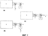
Фиг.1 иллюстрирует предпочтительные варианты применения пучка полых волоконных капиллярных мембран, выполняющего функцию ГХ колонки, скомбинированной с химическим детектором.Figure 1 illustrates the preferred applications of a bundle of hollow fiber capillary membranes, performing the function of a GC column, combined with a chemical detector.
Фиг.2 иллюстрирует один из предпочтительных вариантов осуществления устройства регулировки температуры для пучка полых волоконных капиллярных мембран, выполняющего функцию ГХ колонки. Сверху на фиг.2 показано одиночное полое волокно; справа - вид на конец колонки в направлении потока воздуха.Figure 2 illustrates one of the preferred embodiments of the temperature control device for a bundle of hollow fiber capillary membranes that performs the function of a GC column. Figure 2 shows a single hollow fiber; on the right is a view of the end of the column in the direction of air flow.
Фиг.3 иллюстрирует результат подачи анализируемой смеси через пучок полых волоконных мембран к детектору.Figure 3 illustrates the result of feeding the analyzed mixture through a bundle of hollow fiber membranes to the detector.
Осуществление изобретенияThe implementation of the invention
На фиг.1 показан один из предпочтительных вариантов применения пучка 2 полых волоконных капиллярных мембран, выполняющего функцию ГХ колонки, скомбинированной с химическим детектором 1. Система подачи образца содержит клапан 4, фильтр 3, поглощающий пары, вход 5 для газа и в случае необходимости дополнительный клапан 6. Положение клапана 4 определяет, протекает ли образец к мультикапиллярной ГХ колонке 2 на основе пучка полых волокон через фильтр (клапан 4 установлен в положение (b)) или напрямую (клапан 4 установлен в положение (с)). Момент переключения клапана 4 из положения (b) в положение (с) соответствует значению t=0 для времени удерживания.Figure 1 shows one of the preferred applications of a
Другой предпочтительный вариант осуществления, также показанный на фиг.1, предусматривает наличие дополнительного клапана 6, определяющего, задействована ли ГХ колонка на основе пучка полых волокон (клапан 6 в положении (b) или (с)) или нет (клапан 6 в положении (а)). Когда пучок не используется (положение (а)), время отклика можно уменьшить, однако при применении пучка (клапан 6 в положении (b) или (с)) появляется возможность для более специфической идентификации с меньшей перекрестной чувствительностью.Another preferred embodiment, also shown in FIG. 1, provides for an additional valve 6 that determines whether the GC column is based on a bundle of hollow fibers (valve 6 in position (b) or (c)) or not (valve 6 in position ( but)). When the beam is not used (position (a)), the response time can be reduced, however, when using the beam (valve 6 in position (b) or (c)), it becomes possible for more specific identification with less cross sensitivity.
На фиг.2 показан один из предпочтительных вариантов осуществления устройства регулировки температуры для пучка 2 полых волоконных капиллярных мембран, выполняющего функцию ГХ колонки. Колонка имеет конструкцию, непроницаемую для воздуха, причем оболочка (кожух) 14 колонки изготовлена (изготовлен) из теплоизоляционного материала. Текучая среда (жидкость или газ), для которой предусмотрена возможность контроля термостатирования и нагрева, поступает через отверстия 8 и циркулирует через кожух в направлении 11 с помощью насоса 12. При этом между капиллярами 16 формируется межкапиллярное пространство 7. В одном из предпочтительных вариантов осуществления текучая среда межкапиллярного пространства 7 представляет собой глицерин или промышленный охлаждающий раствор. В другом предпочтительном варианте осуществления такой средой является воздух.Figure 2 shows one of the preferred embodiments of the temperature control device for a
Следующий предпочтительный вариант осуществления использует конструкцию, подобную показанной на фиг.2, но в этом случае система или имеет нагреватель 13, или он отсутствует. В указанном варианте осуществления роль текучей среды межкапиллярного пространства 7 выполняет воздух, причем его главной функцией является очищение системы. Воздух накачивают только во вход 10а колонки, а на противоположном конце для воздуха предусмотрен выход 10 через периферийные отверстия 8, т.е. трубка (шланг) 15 для прокачивания нагревающей среды удалена (удален).A further preferred embodiment uses a design similar to that shown in FIG. 2, but in this case the system either has a heater 13 or is absent. In this embodiment, the role of the fluid of the intercapillary space 7 is played by air, and its main function is to clean the system. Air is pumped only into the inlet 10a of the column, and at the opposite end for air, an
В любом случае текучая среда межкапиллярного пространства 7 изолирована от газообразного образца устройством в виде заглушки 26, 17 у конца трубки. В предпочтительном варианте осуществления заполняющий материал 9 у конца трубки заполняет только пространство между капиллярами и, кроме того, связывает капилляры в одно целое. В одном из предпочтительных вариантов осуществления заполняющим материалом 9 является эпоксидный клей.In any case, the fluid of the intercapillary space 7 is isolated from the gaseous sample by a device in the form of a plug 26, 17 at the end of the tube. In a preferred embodiment, the filling material 9 at the end of the tube fills only the space between the capillaries and, in addition, binds the capillaries together. In one of the preferred embodiments, the filling material 9 is an epoxy adhesive.
В одном из предпочтительных вариантов осуществления пучок 2 представляет собой пучок полых волоконных капиллярных мембран высокоселективного типа, применяемый в промышленном сушильном аппарате. Указанный аппарат имеется в продаже под торговыми марками Drypoint (Beko), MF-Dryer (CKD, Wilkinson), SF-Serie (Whatman, Balston), Sunsep (Zander, SMC), VarioDry (Ultrafilter) и Porous Media (Norgren). Структура капиллярной стенки для этого варианта показана на фиг.2, сверху. В типичном случае она состоит из фактически полого волокна 18, выполняющего функцию основы, и активного плотного слоя (мембраны) 19, покрывающего внутреннюю поверхность.In one preferred embodiment,
В одном из предпочтительных вариантов осуществления детектор 1 представляет собой комбинированный мультисенсорный IMS-спектрометр, имеющийся в продаже под торговыми марками ChemPro100 (Environics), M90-D1-C (Environics), MultiIMS (Drager), или любой другой детектор на основе IMS-спектрометра.In one preferred embodiment,
ПримерExample
Следующий пример иллюстрирует, но не ограничивает основные особенности настоящего изобретения.The following example illustrates, but does not limit the main features of the present invention.
Использованное устройство аналогично устройствам, показанным на фиг.1 и 2. Пучок полых волоконных мембранных капилляров взят из мембранного сушильного аппарата Drypoint (Beko). Детектором является прибор ChemPro100 (Environics), работающий с расходом 1 л/мин.The device used is similar to the devices shown in FIGS. 1 and 2. A bundle of hollow fiber membrane capillaries is taken from a Drypoint (Beko) membrane dryer. The detector is a ChemPro100 (Environics) instrument operating at a flow rate of 1 l / min.
Начальный момент времени (время удерживания равно 0) задают переключением клапана 4 из положения (b) в положение (с) - см. фиг.1.The initial moment of time (retention time is 0) is set by switching valve 4 from position (b) to position (c) - see Fig. 1.
На фиг.3 приведен результат подачи смеси метилсалицилата (MeS) и диизопропилметилфосфоната (DIMP) (1% DIMP и 99% MeS) через пучок полых волоконных мембран к детектору.Figure 3 shows the result of feeding a mixture of methyl salicylate (MeS) and diisopropyl methylphosphonate (DIMP) (1% DIMP and 99% MeS) through a bundle of hollow fiber membranes to the detector.
Первоначально детектор засасывает воздух через фильтр и измеряет чистый фоновый сигнал. Одновременно с началом подачи образца клапан 4 переключили в положение (с). Через 3 с клапан 4 переключили в положение (b). Посредством этой процедуры дозу образца вводят в волокна в интервале между подачами чистого воздуха.Initially, the detector draws in air through a filter and measures a clean background signal. Simultaneously with the beginning of the sample supply, valve 4 was switched to position (c). After 3 s, valve 4 was switched to position (b). Through this procedure, the dose of the sample is introduced into the fibers in the interval between clean air.
В течение 40 секунд оба химических препарата элюировали через колонку и селективно детектировались спектрометром подвижности ионов (DIMP) и газовым датчиком на основе оксида металла (MeS). Если бы образец вводили через клапан 6, установленный в положение (а), между сигналами не было бы задержки по времени.Within 40 seconds, both chemicals were eluted through the column and selectively detected by an ion mobility spectrometer (DIMP) and a metal oxide gas sensor (MeS). If the sample was introduced through the valve 6, set to position (a), there would be no time delay between the signals.
Настоящее изобретение предлагает прибор, применяемый в качестве химического детектора. В более предпочтительном варианте он используется как дополнительное устройство, которое проводит химическое разделение и скомбинировано с любым химическим детектором. Изобретение улучшает химическую специфичность химических детекторов, применяемая аппаратура состоит из недорогих компонентов и облегчает получение прочной конструкции. Оно особенно полезно при использовании для идентификации присутствия химических боевых отравляющих веществ, а также других токсичных и огнеопасных газов и паров в таких приложениях, как военное дело, промышленная или персональная защита, гигиена труда или окружающей среды, а также контроль производственных процессов.The present invention provides a device used as a chemical detector. In a more preferred embodiment, it is used as an additional device that conducts chemical separation and is combined with any chemical detector. The invention improves the chemical specificity of chemical detectors, the equipment used consists of inexpensive components and facilitates the preparation of a robust structure. It is especially useful when used to identify the presence of chemical warfare agents, as well as other toxic and flammable gases and vapors, in applications such as military affairs, industrial or personal protection, occupational or environmental health, and process control.
Claims (22)
Applications Claiming Priority (2)
| Application Number | Priority Date | Filing Date | Title |
|---|---|---|---|
| FI20040098 | 2004-01-23 | ||
| FI20040098A FI117179B (en) | 2004-01-23 | 2004-01-23 | Gas chromatograph |
Publications (2)
| Publication Number | Publication Date |
|---|---|
| RU2006125218A RU2006125218A (en) | 2008-02-27 |
| RU2364862C2 true RU2364862C2 (en) | 2009-08-20 |
Family
ID=30129428
Family Applications (1)
| Application Number | Title | Priority Date | Filing Date |
|---|---|---|---|
| RU2006125218/28A RU2364862C2 (en) | 2004-01-23 | 2005-01-21 | Gas chromatograph |
Country Status (11)
| Country | Link |
|---|---|
| US (1) | US7520159B2 (en) |
| EP (1) | EP1711806B1 (en) |
| JP (1) | JP4903056B2 (en) |
| CN (1) | CN100454019C (en) |
| AT (1) | ATE535803T1 (en) |
| CA (1) | CA2553479A1 (en) |
| FI (1) | FI117179B (en) |
| HK (1) | HK1094465A1 (en) |
| IL (1) | IL176744A0 (en) |
| RU (1) | RU2364862C2 (en) |
| WO (1) | WO2005071395A1 (en) |
Families Citing this family (22)
| Publication number | Priority date | Publication date | Assignee | Title |
|---|---|---|---|---|
| WO2008114828A1 (en) * | 2007-03-20 | 2008-09-25 | National University Corporation Hamamatsu University School Of Medicine | Cell selection method and cell selection apparatus |
| DE102007033906A1 (en) * | 2007-07-20 | 2009-01-29 | Gesellschaft zur Förderung der Analytischen Wissenschaften e.V. | Gas i.e. human exhaled air, analyzing method, involves guiding gas sample that is isothermally conducted from gas sample accommodation into ion mobility spectrometer and is continuously warmed up at retention time |
| US8117895B2 (en) | 2008-06-12 | 2012-02-21 | Northern Alberta Institute Of Technology | Gas chromatography capillary devices and methods |
| US8087283B2 (en) | 2008-06-17 | 2012-01-03 | Tricorntech Corporation | Handheld gas analysis systems for point-of-care medical applications |
| US8999245B2 (en) * | 2009-07-07 | 2015-04-07 | Tricorn Tech Corporation | Cascaded gas chromatographs (CGCs) with individual temperature control and gas analysis systems using same |
| US8707760B2 (en) | 2009-07-31 | 2014-04-29 | Tricorntech Corporation | Gas collection and analysis system with front-end and back-end pre-concentrators and moisture removal |
| US8978444B2 (en) | 2010-04-23 | 2015-03-17 | Tricorn Tech Corporation | Gas analyte spectrum sharpening and separation with multi-dimensional micro-GC for gas chromatography analysis |
| EP2577288B1 (en) * | 2010-06-07 | 2013-11-20 | Commissariat à l'Énergie Atomique et aux Énergies Alternatives | System for analyzing a gas mixture including at least one chromatography column |
| CN104737012A (en) * | 2012-10-25 | 2015-06-24 | 株式会社岛津制作所 | Gas chromatograph device |
| US8841611B2 (en) * | 2012-11-30 | 2014-09-23 | Agilent Technologies, Inc. | Multi-capillary column and high-capacity ionization interface for GC-MS |
| US9895664B2 (en) | 2013-04-25 | 2018-02-20 | Toray Industries, Inc. | Cartridge type hollow fiber membrane module |
| JP6020726B2 (en) * | 2013-07-23 | 2016-11-02 | 株式会社島津製作所 | Gas chromatograph |
| US9664598B2 (en) * | 2013-10-18 | 2017-05-30 | Agilent Technologies, Inc. | Microfluidic contaminant trap for trapping contaminants in gas chromatography |
| CN104515824B (en) * | 2014-12-31 | 2016-08-24 | 同方威视技术股份有限公司 | Gaseous substance analytical equipment and gas phase gatherer |
| CN107093546B (en) | 2014-12-31 | 2019-03-19 | 同方威视技术股份有限公司 | Detection device and detection method |
| US9789434B1 (en) * | 2016-03-28 | 2017-10-17 | Morpho Detection, Llc | Systems and methods for gas pre-separation for detection of substances |
| EP3267192B1 (en) * | 2016-07-07 | 2020-08-19 | Alpha M.O.S. | Gas chromatograph comprising metal oxide sensors |
| DE102016217891A1 (en) * | 2016-09-19 | 2018-03-22 | Inficon Gmbh | Filling probe attachment with elongated gas-conducting element |
| EP4325219A2 (en) * | 2016-11-11 | 2024-02-21 | Cytiva Sweden AB | Chromatography column |
| US11313833B2 (en) * | 2018-08-31 | 2022-04-26 | Leidos Security Detection & Automation, Inc. | Chemical trace detection system |
| WO2020105661A1 (en) * | 2018-11-20 | 2020-05-28 | 株式会社日立ハイテク | Analysis device having plurality of chromatographs and control method for analysis device |
| CN110702817B (en) * | 2019-11-05 | 2023-06-13 | 兰州东立龙信息技术有限公司 | Handheld portable air comprehensive detection equipment |
Family Cites Families (16)
| Publication number | Priority date | Publication date | Assignee | Title |
|---|---|---|---|---|
| CA1221645A (en) * | 1983-02-28 | 1987-05-12 | Yoshihiro Okano | Filtration apparatus using hollow fiber-membrane |
| JPS61265567A (en) * | 1985-05-20 | 1986-11-25 | Fujikura Ltd | Multi-capillary column |
| SE8802126D0 (en) * | 1988-06-07 | 1988-06-07 | Pharmacia Ab | APPARATUS FOR FLOW FIELD FLOW FRACTIONATION |
| US4957620A (en) * | 1988-11-15 | 1990-09-18 | Hoechst Celanese Corporation | Liquid chromatography using microporous hollow fibers |
| US5139668A (en) * | 1989-12-27 | 1992-08-18 | Alberta Research Corporation | Hollow fiber bundle element |
| CN1058272A (en) * | 1991-07-23 | 1992-01-29 | 厦门大学 | Electro-migration micro-ionic chromatographis analyzer |
| DE4234728A1 (en) * | 1992-10-15 | 1994-04-21 | Peter Prof Dr Bartholmes | Process for the recovery and the buffering and / or concentration of dissolved macromolecules of a macromolecule mixture |
| JP3322325B2 (en) * | 1993-12-28 | 2002-09-09 | 独立行政法人産業技術総合研究所 | Sample concentrator for analysis |
| DE19514033A1 (en) * | 1995-04-13 | 1996-10-17 | Huels Chemische Werke Ag | Procedure for the investigation of silane-treated, inorganic materials |
| JPH09159587A (en) * | 1995-12-12 | 1997-06-20 | Nkk Corp | Dehumidifying method and analysis method for analyzed combustion gas |
| JPH10118436A (en) * | 1996-10-18 | 1998-05-12 | Ookura Riken:Kk | Moisture removing device for gas to be analyzed |
| US5856616A (en) * | 1997-03-21 | 1999-01-05 | The United States Of America As Represented By The Secretary Of The Army | Hand-held temperature programmable modular gas chromatograph |
| US6270674B1 (en) * | 1997-06-14 | 2001-08-07 | Akzo Nobel Nv | Membrane module with unilaterally embedded hollow fiber membranes |
| EP1062505A4 (en) * | 1998-02-11 | 2001-02-14 | Lawrence V Haley | Hand-held detection system using gc/ims |
| JP4520621B2 (en) * | 2000-11-01 | 2010-08-11 | 信和化工株式会社 | Chromatographic separation column, solid phase extraction medium, and chromatographic sample injection system |
| DE10227721B4 (en) * | 2002-06-21 | 2008-03-13 | Hermsdorfer Institut Für Technische Keramik E.V. | Process for producing a bundle of ceramic capillaries for a separation module |
-
2004
- 2004-01-23 FI FI20040098A patent/FI117179B/en not_active IP Right Cessation
-
2005
- 2005-01-21 RU RU2006125218/28A patent/RU2364862C2/en not_active IP Right Cessation
- 2005-01-21 AT AT05708129T patent/ATE535803T1/en active
- 2005-01-21 EP EP05708129A patent/EP1711806B1/en not_active Not-in-force
- 2005-01-21 CA CA002553479A patent/CA2553479A1/en not_active Abandoned
- 2005-01-21 JP JP2006550209A patent/JP4903056B2/en not_active Expired - Fee Related
- 2005-01-21 WO PCT/FI2005/000045 patent/WO2005071395A1/en active Application Filing
- 2005-01-21 US US10/586,760 patent/US7520159B2/en not_active Expired - Fee Related
- 2005-01-21 CN CNB2005800028754A patent/CN100454019C/en not_active Expired - Fee Related
-
2006
- 2006-07-06 IL IL176744A patent/IL176744A0/en unknown
-
2007
- 2007-02-07 HK HK07101430.9A patent/HK1094465A1/en not_active IP Right Cessation
Also Published As
| Publication number | Publication date |
|---|---|
| RU2006125218A (en) | 2008-02-27 |
| JP4903056B2 (en) | 2012-03-21 |
| HK1094465A1 (en) | 2007-03-30 |
| WO2005071395A1 (en) | 2005-08-04 |
| EP1711806A1 (en) | 2006-10-18 |
| CN1910453A (en) | 2007-02-07 |
| FI117179B (en) | 2006-07-14 |
| CA2553479A1 (en) | 2005-08-04 |
| US20070256474A1 (en) | 2007-11-08 |
| EP1711806B1 (en) | 2011-11-30 |
| JP2007518997A (en) | 2007-07-12 |
| FI20040098A (en) | 2005-07-24 |
| CN100454019C (en) | 2009-01-21 |
| FI20040098A0 (en) | 2004-01-23 |
| ATE535803T1 (en) | 2011-12-15 |
| US7520159B2 (en) | 2009-04-21 |
| IL176744A0 (en) | 2006-10-31 |
Similar Documents
| Publication | Publication Date | Title |
|---|---|---|
| RU2364862C2 (en) | Gas chromatograph | |
| Yang et al. | Membrane extraction with a sorbent interface for capillary gas chromatography | |
| US8721892B2 (en) | Integrated chromatography devices and systems for monitoring analytes in real time and methods for manufacturing the same | |
| Ohira et al. | A fiber optic sensor with a metal organic framework as a sensing material for trace levels of water in industrial gases | |
| US5235843A (en) | Method and apparatus for analyzing volatile chemical components in a liquid | |
| JPH0774802B2 (en) | Trihalomethane quantification method and analyzer | |
| JP2000509487A (en) | Recirculating filtration device for use with a portable ion mobility analyzer | |
| RU2146811C1 (en) | Technique of ecological monitoring of organic compounds and device for its realization | |
| US6296685B1 (en) | Device and method for sampling in liquid phases using a diffusion body and an analyte-binding phase | |
| US20020182746A1 (en) | Method and device for sample introduction of volatile analytes | |
| US8128873B2 (en) | Gas analyzer cassette system | |
| JPH07506899A (en) | Membrane fluid separation device | |
| US20170322188A1 (en) | Volatile eluent preparation | |
| Boring et al. | Wet effluent parallel plate diffusion denuder coupled capillary ion chromatograph for the determination of atmospheric trace gases | |
| JP2009128177A (en) | Gas analyzer and fuel cell | |
| JP5102816B2 (en) | Gas analyzer with continuous concentration method | |
| US6368559B1 (en) | Device for analyzing organic compounds particularly in aqueous and gaseous samples | |
| US9074972B2 (en) | Surrogate addition device and a method of analyte concentration | |
| WO2021014835A1 (en) | Gas-sensor-based measurement method and measurement device | |
| Chrenko | Infrared Microcell. | |
| SU1157447A1 (en) | Membrane separator | |
| Kuchmenko et al. | Analytical potentialities of the monosensor piezoresonance detection cell with the open and closed inlet | |
| CA2250145C (en) | Recirculating filtration system for use with a transportable ion mobility spectrometer | |
| Akbar et al. | Hybrid Integration of a Preconcentrator with an Integrated Column | |
| Janes et al. | [Pre-print] Modeling analyte permeation in cylindrical hollow fiber membrane introduction mass spectrometry |
Legal Events
| Date | Code | Title | Description |
|---|---|---|---|
| MM4A | The patent is invalid due to non-payment of fees |
Effective date: 20200122 |