RU2349414C2 - Pressure die-casting machine and casting method with usage of such machine - Google Patents
Pressure die-casting machine and casting method with usage of such machine Download PDFInfo
- Publication number
- RU2349414C2 RU2349414C2 RU2006100350/02A RU2006100350A RU2349414C2 RU 2349414 C2 RU2349414 C2 RU 2349414C2 RU 2006100350/02 A RU2006100350/02 A RU 2006100350/02A RU 2006100350 A RU2006100350 A RU 2006100350A RU 2349414 C2 RU2349414 C2 RU 2349414C2
- Authority
- RU
- Russia
- Prior art keywords
- mold
- molten metal
- cylinder
- plate
- plunger
- Prior art date
Links
Images
Classifications
-
- B—PERFORMING OPERATIONS; TRANSPORTING
- B22—CASTING; POWDER METALLURGY
- B22D—CASTING OF METALS; CASTING OF OTHER SUBSTANCES BY THE SAME PROCESSES OR DEVICES
- B22D17/00—Pressure die casting or injection die casting, i.e. casting in which the metal is forced into a mould under high pressure
- B22D17/08—Cold chamber machines, i.e. with unheated press chamber into which molten metal is ladled
-
- B—PERFORMING OPERATIONS; TRANSPORTING
- B22—CASTING; POWDER METALLURGY
- B22D—CASTING OF METALS; CASTING OF OTHER SUBSTANCES BY THE SAME PROCESSES OR DEVICES
- B22D17/00—Pressure die casting or injection die casting, i.e. casting in which the metal is forced into a mould under high pressure
- B22D17/20—Accessories: Details
- B22D17/2015—Means for forcing the molten metal into the die
- B22D17/2053—Means for forcing the molten metal into the die using two or more cooperating injection pistons
-
- B—PERFORMING OPERATIONS; TRANSPORTING
- B22—CASTING; POWDER METALLURGY
- B22D—CASTING OF METALS; CASTING OF OTHER SUBSTANCES BY THE SAME PROCESSES OR DEVICES
- B22D17/00—Pressure die casting or injection die casting, i.e. casting in which the metal is forced into a mould under high pressure
- B22D17/14—Machines with evacuated die cavity
-
- B—PERFORMING OPERATIONS; TRANSPORTING
- B22—CASTING; POWDER METALLURGY
- B22D—CASTING OF METALS; CASTING OF OTHER SUBSTANCES BY THE SAME PROCESSES OR DEVICES
- B22D17/00—Pressure die casting or injection die casting, i.e. casting in which the metal is forced into a mould under high pressure
- B22D17/20—Accessories: Details
- B22D17/2015—Means for forcing the molten metal into the die
- B22D17/203—Injection pistons
-
- B—PERFORMING OPERATIONS; TRANSPORTING
- B22—CASTING; POWDER METALLURGY
- B22D—CASTING OF METALS; CASTING OF OTHER SUBSTANCES BY THE SAME PROCESSES OR DEVICES
- B22D17/00—Pressure die casting or injection die casting, i.e. casting in which the metal is forced into a mould under high pressure
- B22D17/20—Accessories: Details
- B22D17/30—Accessories for supplying molten metal, e.g. in rations
-
- B—PERFORMING OPERATIONS; TRANSPORTING
- B22—CASTING; POWDER METALLURGY
- B22D—CASTING OF METALS; CASTING OF OTHER SUBSTANCES BY THE SAME PROCESSES OR DEVICES
- B22D27/00—Treating the metal in the mould while it is molten or ductile ; Pressure or vacuum casting
- B22D27/15—Treating the metal in the mould while it is molten or ductile ; Pressure or vacuum casting by using vacuum
Abstract
Description
Область техникиTechnical field
Настоящее изобретение относится к машинам для литья под давлением и способам литья с использованием таких машин, где расплавленный металл (расплавленная жидкость) перемещается горизонтально и вводится в камеру, а затем расплавленный металл перемещается вертикально и инжектируется в пресс-форму с подвижной полуформой и неподвижной полуформой, расположенной вертикально, благодаря чему предотвращается генерирование теплового потока расплавленного металла, введенного в пресс-форму, чтобы получить изделие хорошего качества без раковин.The present invention relates to injection molding machines and injection methods using such machines, where the molten metal (molten liquid) is moved horizontally and introduced into the chamber, and then the molten metal is moved vertically and injected into the mold with a movable half-mold and a fixed half-mold, vertically positioned, thereby preventing the generation of a heat flow of molten metal introduced into the mold in order to obtain a good quality product without sinks.
Кроме того, настоящее изобретение относится к машинам для литья под давлением, имеющим вакуум-аппарат, а также к способам литья с использованием таких машин, в которых металл вводят в вакуумный бачок, в котором расположен плавильный тигель, через пару клапанов, а другой клапан также расположен даже в отверстии слива расплавленного металла вакуумного бачка, чтобы удержать степень разрежения внутри вакуумного бачка в высоком состоянии, благодаря чему изделие хорошего качества может быть произведено из сплава, имеющего высокую точку плавления, который легко окисляется на воздухе.In addition, the present invention relates to injection molding machines having a vacuum apparatus, as well as to casting methods using such machines in which metal is introduced into the vacuum tank in which the melting crucible is located, through a pair of valves, and another valve also even located in the drain hole of the molten metal of the vacuum tank in order to keep the vacuum level inside the vacuum tank in a high state, so that a good quality product can be made from an alloy having a high melting point ny, which is easily oxidized in air.
Предшествующий уровень техникиState of the art
Формование с использования разливочной машины включает нагнетание расплавленного металла в пресс-форму под давлением и выдерживание металла под давлением до затвердения. Этот способ широко использовался благодаря точности отливок, уменьшения обработки резанием и т.п.Molding using a casting machine involves injecting molten metal into a mold under pressure and holding the metal under pressure until it hardens. This method has been widely used due to the precision of castings, reduction of machining, etc.
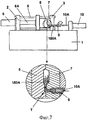
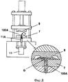
Как показано на фиг.7 и фиг.8, обычные машины для литья под давлением могут подразделяться на машины для литья под давлением горизонтального типа, т.е в которых расплавленный металл (расплавленная жидкость) движется горизонтально, и машины для литья под давлением вертикального типа, т.е в которых расплавленный металл движется вертикально. В машине для литья под давлением горизонтального типа, когда расплавленный металл подается горизонтально под давлением и инжектируется в пресс-форму плунжером, из-за неблагоприятного теплового потока в L-образно изогнутой части (Т) возникают пузырьки (см. фиг.7). Точно также в машине для литья под давлением вертикального типа, когда расплавленный металл подается вертикально под давлением и инжектируется в пресс-форму плунжером, из-за неблагоприятного теплового потока в изогнутой части (Q) также возникают пузырьки (см. фиг.8).As shown in FIGS. 7 and 8, conventional injection molding machines can be divided into horizontal injection molding machines, that is, in which molten metal (molten liquid) moves horizontally, and vertical injection molding machines , i.e. in which molten metal moves vertically. In a horizontal injection molding machine, when molten metal is fed horizontally under pressure and injected into the mold by a plunger, bubbles arise in the L-shaped curved part (T) due to an unfavorable heat flow (see Fig. 7). Similarly, in a vertical type injection molding machine, when molten metal is fed vertically under pressure and is injected into the mold by a plunger, bubbles also arise in the curved portion (Q) due to an unfavorable heat flow (see FIG. 8).
Из-за вышесказанного в готовом изделии появляются раковины. Из-за большого количества бракованных отливок достаточно трудно получить изделия хорошего и высокого качества при использовании обычной машины для литья под давлением.Because of the above, sinks appear in the finished product. Due to the large number of defective castings, it is quite difficult to obtain products of good and high quality when using a conventional injection molding machine.
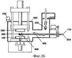
Кроме того, известен обычный вакуум-аппарат машины для литья под давлением для производства изделий высокого качества в вакууме за счет закрытия от кислорода воздуха сплава с высокой точкой плавления, который легко окисляется кислородом воздуха. Обычный вакуум-аппарат имеет конструкцию, включающую неподвижную полуформу 100, подвижную полуформу 200, стержень основания 400, в который вставлены труба 110 циркулирующего охладителя индукционной катушки и кабель 900 источника питания, плавильный тигель 300, к которому прикреплена высокочастотная индукционная катушка 800, и клещи 500 для подачи металла в кристаллизатор 300, причем все элементы окружены одним вакуумным бачком 600. В этой конструкции, однако, теряется много времени, чтобы создать вакуум внутри вакуумного бачка 600 с помощью вакуумного насоса 700. Также степень вакуума внутри вакуумного бачка 600 недостаточно высока.In addition, a conventional vacuum apparatus of an injection molding machine is known for producing high quality products in a vacuum by closing a high melting point alloy from oxygen in the air, which is easily oxidized by atmospheric oxygen. A conventional vacuum apparatus has a structure including a fixed half-
Таким образом существует проблема, заключающаяся в том, что отливки хорошего качества не производятся из сплава с высокой точкой плавления, который легко окисляется воздухом.Thus, there is a problem that good quality castings are not made from a high melting point alloy that is easily oxidized by air.
Раскрытие изобретенияDisclosure of invention
Соответственно настоящее изобретение было сделано ввиду существования вышеизложенных проблем, а целью настоящего изобретения является создание машины для литья под давлением, в которой расплавленный металл нагнетается вертикально под давлением и инжектируется в пресс-форму с неподвижной полуформой и подвижной полуформой, расположенных вертикально, с помощью соответственно объединения машины горизонтального типа, в которой расплавленный металл нагнетается горизонтально под давлением, и машины вертикального типа, в которой расплавленный металл нагнетается вертикально под давлением, посредством чего тепловой поток двигающегося расплавленного металла имеет оптимальную форму для производства изделий высокого качества с точным строением и без раковин.Accordingly, the present invention was made in view of the above problems, and an object of the present invention is to provide an injection molding machine in which molten metal is injected vertically under pressure and injected into a mold with a fixed half mold and a movable half mold arranged vertically by combining accordingly a horizontal type machine in which molten metal is injected horizontally under pressure, and a vertical type machine in which the melt enny metal is forced under pressure vertically, thereby moving the heat flow of the molten metal has an optimum shape to produce high quality products with precise structure and free from voids.
Другой целью настоящего изобретения является создание вакуум-аппарата машины для литья под давлением, в котором имеется клапан и вакуумный бачок, расположенные у горизонтальной инжекционной втулки для подачи расплавленного металла существующей машины для литья под давлением, плавильный тигель для быстрого производства расплавленной жидкости с высоким состоянием вакуума посредством вакуумного насоса, расположенный в вакуумном бачке, и пара клапанов, соединенных с инжекционной втулкой для подачи металла в вакуумный бачок в нормальном вакуумном состоянии, расположенная в секции подачи металла вакуумного бачка, посредством чего металл расплавляется внутри вакуумного бачка в состоянии сильной степени разряжения, при котором кислород воздуха едва воздействует на окисление, за счет чего производят изделия из сплава с высокой точки плавления с хорошим качеством.Another objective of the present invention is to provide a vacuum apparatus for an injection molding machine in which there is a valve and a vacuum tank located at the horizontal injection sleeve for supplying molten metal to an existing injection molding machine, a melting crucible for the rapid production of molten liquid with a high vacuum state by means of a vacuum pump located in the vacuum tank, and a pair of valves connected to the injection sleeve for supplying metal to the vacuum tank in normal vacuum state, an metal supply section of the vacuum tank, whereby the metal is melted within the vacuum tank in a state of strong vacuum degree at which the oxygen in the air hardly affects the oxidation, thereby producing an alloy product of a high melting point with good quality.
Для достижения вышеуказанных целей в соответствии с настоящим изобретением предлагается машина для литья под давлением, содержащая пару суппортов, расположенных противоположно друг другу на станине, направляющий стержень, соединяющий суппорты, подвижную опорную плиту, установленную на направляющем стержне с возможностью перемещения вдоль него с помощью штока первого цилиндра, прикрепленного к первому суппорту, подвижную полуформу и плиту крепления подвижной полуформы, расположенные на одной стороне подвижной опорной плиты, второй цилиндр, установленный с другой стороны подвижной опорной плиты, плиту толкателя, прикрепленную к штоку второго цилиндра, толкатель для выталкивания отливки из подвижной полуформы, прикрепленный к плите толкателя, горизонтальную инжекционную втулку для подачи расплавленного металла и плиту крепления неподвижной полуформы, установленные на одной стороне второго суппорта, неподвижную полуформу, имеющую отверстие для расплавленного металла, опорный стержень, установленный на другой стороне второго суппорта, дополнительную опорную плиту, расположенную на конце опорного стержня, третий цилиндр, прикрепленный к дополнительной опорной плите, плунжер которого предназначен для перемещения расплавленного металла в горизонтальную инжекционную втулку, закрепленную на плитах крепления полуформ, вертикальную камеру для заполнения расплавленным металлом из горизонтальной инжекционной втулки и подачи его в рабочую полость, сформированную неподвижной полуформой и подвижной полуформой, четвертый цилиндр с плунжером для перемещения расплавленного металла из вертикальной камеры в рабочую полость, при этом второй суппорт выполнен с выступом для крепления неподвижной полуформы и выступом для установки четвертого цилиндра с плунжером, а верхняя часть станины выполнена с уклоном вниз от неподвижной полуформы к подвижной полуформе.To achieve the above objectives, in accordance with the present invention, there is provided an injection molding machine comprising a pair of calipers located opposite to each other on a bed, a guide rod connecting the calipers, a movable support plate mounted on the guide rod with the possibility of moving along it using the rod of the first a cylinder attached to the first support, a movable half-mold and a mounting plate of a movable half-mold located on one side of the movable base plate, the second a cylinder mounted on the other side of the movable base plate, a pusher plate attached to the rod of the second cylinder, a pusher for ejecting castings from the movable half-plate, attached to the pusher plate, a horizontal injection sleeve for supplying molten metal and a fixing plate for the fixed half-plate mounted on one side of the second a support, a fixed half-mold having an opening for molten metal, a support rod mounted on the other side of the second support, an additional support plate located at the end of the support rod, a third cylinder attached to an additional support plate, the plunger of which is designed to move the molten metal into a horizontal injection sleeve mounted on the half-plate mounting plates, a vertical chamber for filling with molten metal from the horizontal injection sleeve and feeding it into the working cavity formed by a fixed half-mold and a movable half-mold, the fourth cylinder with a plunger for moving molten metal from a vertical chamber ry into the working cavity, while the second caliper is made with a protrusion for fastening the fixed half-mold and a protrusion for installing the fourth cylinder with a plunger, and the upper part of the bed is made with a downward slope from the fixed half-mold to the movable half-mold.
Также в соответствии с настоящим изобретением предлагается машина для литья под давлением, содержащая пару суппортов, расположенных противоположно друг другу на станине, направляющий стержень, соединяющий суппорты, подвижную опорную плиту, установленную на направляющем стержне с возможностью перемещения вдоль него с помощью штока первого цилиндра, прикрепленного к первому суппорту, подвижную полуформу и плиту крепления подвижной полуформы, расположенные на одной стороне подвижной опорной плиты, второй цилиндр, установленный с другой стороны подвижной опорной плиты, плиту толкателя, прикрепленную к штоку второго цилиндра, толкатель для выталкивания отливки из подвижной полуформы, прикрепленный к плите толкателя, горизонтальную инжекционную втулку для подачи расплавленного металла и плиту крепления неподвижной полуформы, установленные на одной стороне второго суппорта, неподвижную полуформу, имеющую отверстие для расплавленного металла, опорный стержень, установленный на другой стороне второго суппорта, дополнительную опорную плиту, расположенную на конце опорного стержня, третий цилиндр, прикрепленный к дополнительной опорной плите, плунжер которого предназначен для перемещения расплавленного металла в горизонтальную инжекционную втулку, закрепленную на плитах крепления полуформ, вертикальную камеру для заполнения расплавленным металлом из горизонтальной инжекционной втулки и подачи его в рабочую полость, сформированную неподвижной полуформой и подвижной полуформой, четвертый цилиндр с плунжером для перемещения расплавленного металла из вертикальной камеры в рабочую полость, при этом второй суппорт выполнен с выступом для крепления неподвижной полуформы и выступом для установки четвертого цилиндра с плунжером, кроме того, машина содержит вакуумный бачок, соединенный с вакуумным насосом, трубу подачи металла в вакуумный бачок; два или более клапана, расположенных в трубе подачи металла для предотвращения попадания воздуха в вакуумный бачок при подаче металла, пятый цилиндр с плунжером для подачи металла в вакуумный бачок, плавильный тигель, расположенный в вакуумном бачке, зубчатую рейку и ведущую шестерню, осуществляющих наклон плавильного тигля для подачи расплавленного металла в горизонтальную инжекционную втулку, причем в днище вакуумного бачка выполнено отверстие слива расплавленного металла в горизонтальную инжекционную втулку, а на нижней стороне вакуумного бачка расположен пластинчатый клапан для открытия и закрытия отверстия слива расплавленного металла, при этом один из двух или более клапанов, установленных на трубе подачи металла, содержит пластину клапана, в которой выполнено гнездо для подачи через него металла посредством плунжера.Also in accordance with the present invention, there is provided an injection molding machine comprising a pair of calipers located opposite to each other on a bed, a guide rod connecting the calipers, a movable support plate mounted on the guide rod with the possibility of moving along it using the rod of the first cylinder attached to the first caliper, the movable half-mold and the mounting plate of the movable half-mold, located on one side of the movable base plate, the second cylinder mounted on the other the sides of the movable base plate, the plunger plate attached to the rod of the second cylinder, the pusher for pushing the casting from the movable mold, attached to the plunger plate, the horizontal injection sleeve for supplying molten metal and the fixed mount mold mounting plate mounted on one side of the second caliper, fixed mold, having an opening for molten metal, a support rod mounted on the other side of the second caliper, an additional support plate located at the end of the supports of the second rod, a third cylinder attached to an additional base plate, the plunger of which is designed to move molten metal into a horizontal injection sleeve mounted on the half-plate mounting plates, a vertical chamber for filling with molten metal from the horizontal injection sleeve and feeding it into the working cavity formed by the fixed half-mold and a movable half-mold, a fourth cylinder with a plunger for moving molten metal from a vertical chamber into the working cavity, while the second support is made with a protrusion for attaching a fixed half-mold and a protrusion for installing a fourth cylinder with a plunger, in addition, the machine contains a vacuum tank connected to a vacuum pump, a metal supply pipe to the vacuum tank; two or more valves located in the metal supply pipe to prevent air from entering the vacuum tank when feeding metal, a fifth cylinder with a plunger for supplying metal to the vacuum tank, a melting crucible located in the vacuum tank, a gear rack and pinion gear tilting the melting crucible for supplying molten metal to the horizontal injection sleeve, and in the bottom of the vacuum tank there is a hole for draining the molten metal into the horizontal injection sleeve, and on the bottom side a plate valve is located in the cum tank for opening and closing the drain hole of molten metal, while one of two or more valves installed on the metal supply pipe comprises a valve plate in which a socket is provided for supplying metal through it by means of a plunger.
Кроме этого, вакуумный бачок соединен с горизонтальной инжекционной втулкой, чтобы расплавленный металл, расплавленный в плавильном тигле внутри вакуумного бачка, был подан под давлением в рабочую полость пресс-формы, сформированную комбинацией неподвижной полуформы и подвижной полуформы, и затем отлит.In addition, the vacuum tank is connected to the horizontal injection sleeve so that molten metal, molten in a melting crucible inside the vacuum tank, is fed under pressure into the working cavity of the mold, formed by a combination of a fixed mold and a movable mold, and then cast.
Также в соответствии с настоящим изобретением предлагается способ литья под давлением расплавленного металла, включающий горизонтальную инжекцию расплавленного металла из горизонтальной инжекционной втулки в вертикальную камеру и вертикальную инжекцию расплавленного металла плунжером в рабочую полость пресс-формы, установленной на заявляемой машине для литья под давлением.Also in accordance with the present invention, there is provided a method for injection molding molten metal, comprising horizontal injection of molten metal from a horizontal injection sleeve into a vertical chamber and vertical injection of molten metal with a plunger into the working cavity of a mold mounted on the inventive injection molding machine.
Неподвижная полуформа и подвижная полуформа расположены вертикально, а расплавленный металл сначала перемещается горизонтально. Затем расплавленный металл перемещается к плунжеру так, чтобы заполнить камеру. После того как отверстие инжекции расплавленного металла в неподвижной полуформе закрывается плунжером, расплавленный металл перемещается плунжером вертикально и входит в пресс-форму, которая расположена вертикально. Плотность и механическая прочность отливки являются высокими, так как не генерируются раковины благодаря отсутствию теплового потока. Отливка получается с высоким качеством, с гладкой поверхностью. Выход годного продукта высокого качества увеличивается.The fixed half-mold and the movable half-mold are arranged vertically, and the molten metal first moves horizontally. Then the molten metal moves to the plunger so as to fill the chamber. After the injection hole of the molten metal in the fixed half-mold is closed by the plunger, the molten metal is moved by the plunger vertically and enters the mold, which is located vertically. The density and mechanical strength of the castings are high since no sinks are generated due to the lack of heat flow. The casting is obtained with high quality, with a smooth surface. The yield of high-quality product is increasing.
Кроме того, согласно настоящему изобретению вакуум-аппарат соединен с горизонтальной инжекционной втулкой машины для литья под давлением. Даже в то время, когда металл вводится в вакуум-аппарат, металл расплавляется внутри вакуум-аппарата в состоянии вакуума, причем всегда поддерживается состояние высокого разрежения. Таким образом, металл отливается в рабочую полость пресс-формы, которая сформирована неподвижной полуформой и подвижной полуформой, через горизонтальную инжекционную втулку. Соответственно настоящее изобретение имеет то преимущество, что возможно изготовление отливок хорошего качества из сплава с высокой точкой плавления.In addition, according to the present invention, a vacuum apparatus is connected to a horizontal injection sleeve of an injection molding machine. Even at the time when the metal is introduced into the vacuum apparatus, the metal is melted inside the vacuum apparatus in a vacuum state, and a high rarefaction state is always maintained. Thus, the metal is cast into the working cavity of the mold, which is formed by a fixed half-mold and a moving half-mold, through a horizontal injection sleeve. Accordingly, the present invention has the advantage that it is possible to produce good quality castings from a high melting point alloy.
Краткое описание чертежейBrief Description of the Drawings
Далее цели и преимущества изобретения могут быть более полно поняты из последующего подробного описания, связанного с сопровождающими его чертежами, на которых представлено:Further, the objectives and advantages of the invention can be more fully understood from the following detailed description associated with the accompanying drawings, in which:
фиг.1 - вид в перспективе, показывающий полную конструкцию машины для литья под давлением в соответствии с настоящим изобретением;figure 1 is a perspective view showing the complete structure of the injection molding machine in accordance with the present invention;
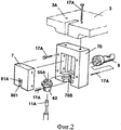
фиг.2 - вид в перспективе, показывающий основные узлы машины для литья под давлением, представленной на фиг.1, в соответствии с настоящим изобретением;figure 2 is a perspective view showing the main components of the injection molding machine shown in figure 1, in accordance with the present invention;
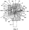
фиг.3 - вид в поперечном разрезе, показывающий действие некоторых узлов машины для литья под давлением в соответствии с одним осуществлением согласно настоящему изобретению;FIG. 3 is a cross-sectional view showing the action of some components of an injection molding machine in accordance with one embodiment of the present invention; FIG.
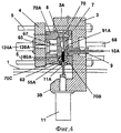
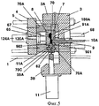
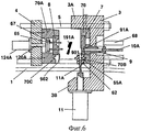
фиг.4 - 6 - виды в поперечном разрезе, последовательно показывающие действие машины для литья под давлением в соответствии с настоящим изобретением;4 to 6 are cross-sectional views sequentially showing the action of an injection molding machine in accordance with the present invention;
фиг.7 схематически показывает конструкцию обычной горизонтальной машины для литья под давлением;7 schematically shows the structure of a conventional horizontal injection molding machine;
фиг.8 схематически показывает конструкцию обычной вертикальной машины для литья под давлением;Fig. 8 schematically shows the structure of a conventional vertical injection molding machine;
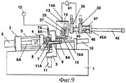
фиг.9 показывает конструкцию машины для литья под давлением, в которой к машине для литья под давлением, показанной на фиг.1, присоединен вакуумный бачок для плавки металла;Fig.9 shows the design of the injection molding machine, in which a vacuum tank for melting metal is attached to the injection molding machine shown in Fig.1;
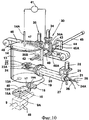
фиг.10 - вид в перспективе, показывающий конструкцию вакуумного бачка, представленного на фиг.9;figure 10 is a perspective view showing the design of the vacuum tank shown in figure 9;
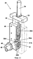
фиг.11 - вид с частичным разрезом, показывающий клапан, представленный на фиг.9;11 is a partially cutaway view showing the valve of FIG. 9;
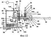
фиг.12 - вид в поперечном разрезе вакуумного бачка, показанного на фиг.10;Fig. 12 is a cross-sectional view of the vacuum tank shown in Fig. 10;
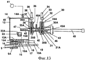
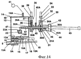
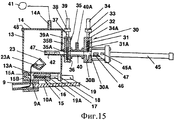
фиг.13 - 15 - виды в поперечном разрезе, последовательно показывающие действие машины для литья под давлением в соответствии с другим осуществлением настоящего изобретения; и13 to 15 are cross-sectional views sequentially showing the operation of an injection molding machine in accordance with another embodiment of the present invention; and
фиг.16 схематически показывает конструкцию машины для литья под давлением, включающей обычный вакуумный бачок.Fig. 16 schematically shows the construction of an injection molding machine including a conventional vacuum tank.
Наилучший вариант осуществления изобретенияBest Mode for Carrying Out the Invention
Сейчас настоящее изобретение будет описано подробно в связи с предпочтительными вариантами осуществления со ссылками на сопровождающие чертежи.The present invention will now be described in detail in connection with preferred embodiments with reference to the accompanying drawings.
Как показано на фиг.1-6, машина для литья под давлением в соответствии с настоящим изобретением включает два суппорта 2 и 3, которые расположены с противоположных сторон на станине 1, направляющий стержень 5, который соединяет суппорты 2 и 3 для направления подвижной опорной плиты 4, и подвижную опорную плиту 4, подвижно закрепленную на направляющем стержне 5 так, что плита 4 движется вдоль направляющего стержня 5 с помощью штока 6А первого цилиндра 6, прикрепленного к одному из суппортов 2 и 3.As shown in FIGS. 1-6, the injection molding machine in accordance with the present invention includes two
Подвижная полуформа 8 и плита крепления подвижной полуформы 70А расположены на одной стороне подвижной опорной плиты 4, а второй цилиндр 124А установлен с другой стороны подвижной опорной плиты 4. Плита толкателя 65, к которой прикреплен толкатель 67 для выталкивания сформированного изделия 191А из подвижной полуформы 8, прикреплена к штоку 120А второго цилиндра 124А. Горизонтальная инжекционная втулка 9 и плита крепления неподвижной полуформы 70 установлены на одной стороне другого из суппортов 2 и 3. Неподвижная полуформа 7, имеющая отверстие для расплавленного металла 91 А, прикреплена к плите крепления неподвижной полуформы 70. Опорный стержень 68 установлен на другой стороне другого из суппортов 2 и 3. Далее, дополнительная опорная плита 131А расположена на конце опорного стержня 68. Третий цилиндр 10 прикреплен к дополнительной опорной плите 131А так, чтобы плунжер 10А третьего цилиндра 10 толкал расплавленный металл в горизонтальную инжекционную втулку 9. Таким образом, металл отливается в пределах рабочей полости, сформированной неподвижной полуформой 7 и подвижной полуформой 8 в соответствии с формой отливки.The
В вышеупомянутой конструкции верхняя часть станины 1 сформирована с уклоном вниз от неподвижной полуформы 7 к подвижной полуформе 8. Суппорт 3 из числа суппортов 2 и 3, к которому прикреплена неподвижная полуформа 7, включает выступ 3А, имеющий прикрепленную к нему неподвижную полуформу 7, и выступ установки цилиндра 3В, к которому прикреплен четвертый цилиндр 11. Неподвижная полуформа 7 закреплена на выступе 3А. Четвертый цилиндр 11 для приведения в движение плунжера 11А закреплен на выступе установки цилиндра 3В. Вертикальная камера 62 с камерой 55А для расплавленного металла 180А и подачи его в рабочую полость на ее вершине закреплена на плитах крепления полуформ 70 и 70А.In the aforementioned structure, the upper part of the
Таким образом, согласно настоящему изобретению, для формирования относительно тонкой и широкой отливки 191А предпочтительно, чтобы рабочая полость, сформированная комбинацией неподвижной полуформы 7 и подвижной полуформы 8, была сформировано в вертикальном направлении по отношению к основанию.Thus, according to the present invention, for forming a relatively thin and
Далее, более предпочтительно, когда при инжекции и формовании расплавленного металла в рабочей полости верхняя часть станины 1 выполнена с уклоном от неподвижной полуформы 7 к подвижной полуформе 8.Further, it is more preferable when, during injection and molding of molten metal in the working cavity, the upper part of the
Благодаря такой конструкции расплавленный металл 180А течет в горизонтальном направлении с уклоном и затем входит в камеру 55А вертикальной камеры 62, которая расположена у основания рабочей полости. Как было упомянуто выше, расплавленный металл 180А поднимается за счет плунжера 11А и перемещается в вертикальном направлении и вводится в рабочую полость с последующим формованием в ней.Due to this design,
Соответственно как показано на фиг.7 и фиг.8, тепловой поток расплавленного металла, который обычно появляется в обычной горизонтальной машине для литья под давлением при горизонтальной подаче под давлением расплавленного металла 180А, а также в обычной вертикальной машине для литья под давлением при вертикальной подаче под давлением расплавленного металла 180 не имеет места в предлагаемой машине. Таким образом возможно изготовить отливку 191А высокого качества с прекрасной структурой и без раковин.Accordingly, as shown in FIGS. 7 and 8, the heat flux of molten metal that typically appears in a conventional horizontal injection molding machine for horizontal injection of
Касаясь вышеизложенного, можно сказать, что машина для литья под давлением включает пару суппортов 2 и 3, которые расположены с противоположных сторон на станине 1, направляющий стержень 5, который соединяет суппорты 2 и 3 для направления подвижной опорной плиты 4, и подвижную опорную плиту 4, подвижно закрепленную на направляющем стержне 5 так, что плита 4 движется вдоль направляющего стержня 5 с помощью штока 6А первого цилиндра 6, прикрепленного к одному из суппортов 2 и 3, подвижную полуформу 8 и плиту крепления подвижной полуформы 70А, расположенные на одной стороне подвижной опорной плиты 4, второй цилиндр 124А установлен с другой стороны подвижной опорной плиты 4, плиту толкателя 65, к которой прикреплен толкатель 67 для выталкивания сформированного изделия 191А из подвижной полуформы 8, который прикреплен к штоку 120А второго цилиндра, горизонтальную инжекционную втулку 9 и плиту крепления неподвижной полуформы 70, установленные на одной стороне другого из суппортов 2 и 3, неподвижную полуформу 7, имеющую отверстие для расплавленного металла 91А, прикрепленную к плите крепления неподвижной полуформы 70, опорный стержень 68, установленный на другой стороне другого из суппортов 2 и 3, дополнительную опорную плиту 131А, расположенную на конце опорного стержня 68, и третий цилиндр 10, прикрепленный к дополнительной опорной плите 131А так, чтобы плунжер 10А третьего цилиндра 10 толкал расплавленный металл в горизонтальную инжекционную втулку 9, посредством чего металл отливается в пределах рабочей полости, сформированной неподвижной полуформой 7 и подвижной полуформой 8 в соответствии с формой отливки, а также подвижную полуформу 8, известную из уровня техники до подачи этой заявки.Regarding the foregoing, it can be said that the injection molding machine includes a pair of calipers 2 and 3, which are located on opposite sides on the bed 1, a guide rod 5, which connects the calipers 2 and 3 to guide the movable base plate 4, and the movable base plate 4 movably mounted on the guide rod 5 so that the plate 4 moves along the guide rod 5 using the rod 6A of the first cylinder 6 attached to one of the calipers 2 and 3, the movable half mold 8 and the mounting plate of the movable half mold 70A, located located on one side of the movable base plate 4, the second cylinder 124A is mounted on the other side of the movable base plate 4, the pusher plate 65 to which the pusher 67 is attached to push the formed product 191A from the movable half mold 8, which is attached to the rod 120A of the second cylinder, horizontal injection the sleeve 9 and the mounting plate of the fixed half mold 70, mounted on one side of the other of the calipers 2 and 3, the fixed half of the mold 7, having a hole for molten metal 91A, attached to the mounting plate a half mold 70, a support rod 68 mounted on the other side of the other of the calipers 2 and 3, an additional support plate 131A located at the end of the support rod 68, and a third cylinder 10 attached to the additional support plate 131A so that the plunger 10A of the third cylinder 10 pushed molten metal into the horizontal injection sleeve 9, whereby the metal is cast within the working cavity formed by the fixed half-mold 7 and the moving half-mold 8 in accordance with the casting form, as well as the moving half-mold 8, from estno the art before the filing of this application.
В вышеупомянутой конструкции, в то время как подвижная полуформа 8 перемещается вправо или влево относительно неподвижной полуформы 7, формируется рабочая полость за счет сочетания неподвижной полуформы 7 и подвижной полуформы 8. Расплавленный металл 180А подается в рабочую полость и затем формуется. Затем подвижная полуформа 8 отделяется от неподвижной полуформы 7.In the aforementioned design, while the
Далее отливка 191А отделяется от подвижной полуформы 8 за счет плиты толкателя 65 и толкателя 67, прикрепленного к нему. Поэтому подвижная полуформа 8 и плита толкателя 65 могут работать автоматически.Next, the casting 191A is separated from the movable half-
Более подробно, для того чтобы соединить подвижную полуформу 8 с неподвижной полуформой 7, используют первый цилиндр 6, чтобы переместить шток 6А вперед, при этом подвижная опорная плита 4, прикрепленная к штоку 6А, перемещается по направлению к суппорту 3, на котором закреплена неподвижная полуформа 7. Таким образом неподвижная полуформа 7 и подвижная полуформа 8 объединяются, формируя рабочую полость, т.е. пространство для формования. Затем, когда расплавленный металл 180А подается через горизонтальную инжекционную втулку 9, закрепленную на суппорте 3, расплавленный металл 180А вводится в рабочую полость и после остывания в ней превращается в отливку 191 А.In more detail, in order to connect the
В это же время для подачи расплавленного металла 180А в рабочую полость используется третий цилиндр 10, закрепленный на дополнительной опорной плите 131А, и расплавленный металл таким образом выталкивается в горизонтальную инжекционную втулку 9 посредством плунжера 10А, направляемого третьим цилиндром 10. Таким образом, расплавленный металл вводится в рабочую полость, сформированную неподвижной полуформой 7 и подвижной полуформой 8. Затем, после истечения некоторого времени, первый цилиндр 6 начинает работать, чтобы переместить шток 6А назад, и подвижная полуформа 8 отделяется от неподвижной полуформы 7.At the same time, for supplying
После этого используют второй цилиндр 124А, закрепленный на подвижной опорной плите 4, чтобы переместить шток 120А вперед и таким образом переместить вперед плиту толкателя 65, при этом отливка 191А, приложенная к подвижной полуформе 8, отделяется от нее толкателем 67, закрепленным на плите толкателя 65, как показано на фиг.6. Т.о. отливка 191А формируется за счет выполнения серии вышеупомянутых операций.After that, a
Согласно настоящему изобретению, в частности, чтобы способствовать потоку расплавленного металла 180А, верхняя часть станины 1 сформирована с уклоном вниз от неподвижной полуформы 7 к подвижной полуформе 8. Горизонтальная инжекционная втулка 9 может быть также выполнена с уклоном и затем присоединена к плите крепления неподвижной полуформы 70 суппорта 3. Однако могут возникнуть неудобства из-за непосредственного контакта между горизонтальной инжекционной втулкой 9 и плитой крепления неподвижной полуформы. Соответственно предпочтительней, когда вся верхняя часть станины 1, на которой установлены суппорты 2 и 3, сформирована с уклоном относительно основания, как описано выше.According to the present invention, in particular, in order to facilitate the flow of
Кроме этого, суппорт 3, на котором между суппортами 2 и 3 установлена неподвижная полуформа 7, включает выступ 3А, имеющий закрепленную на нем неподвижную полуформу 7, и выступ установки цилиндра 3В, к которому прикреплен четвертый цилиндр 11. Неподвижная полуформа 7 установлена на выступе 3А, а четвертый цилиндр 11 для привода плунжера 11А установлен на выступ установки цилиндра 3В. Поэтому плунжер 11А сначала выталкивает расплавленный металл 180А, который находится в камере 55А вертикальной камеры 62, в рабочую полость вверх в вертикальном направлении. В то же время четвертый цилиндр 11, приводящий в движение плунжер 11А, может быть установлен непосредственно под рабочей полостью, которая сформирована комбинацией неподвижной полуформы 7 и подвижной полуформы 8. Вертикальная камера 62 вставлена в полукруглые втулочные пазы 70В и 70С, выполненные в плитах крепления полуформ 70 и 70А. В вышеупомянутой конструкции для подачи расплавленного металла 180А из камеры 55А вертикальной камеры 62 в рабочую полость в неподвижной полуформе 7 и подвижной полуформе 8 выполнены полукруглые вертикальные канавки инжекции расплавленного металла 901 и 902. Четвертый цилиндр 11, который приводит в действие плунжер 11А, установлен на выступ крепления цилиндра 3В у верхней части вертикальной камеры 62.In addition, the
Поэтому, как показано на фиг.3 и фиг.4, расплавленный металл 180А, находящийся в горизонтальной инжекционной втулке 9, подается под давлением посредством плунжера 10А третьего цилиндра 10 и затем заполняет камеру 55А вертикальной камере 62 через отверстие для расплавленного металла 91А и полукруглые вертикальные канавки инжекции расплавленного металла 901 и 902, которые выполнены в неподвижной полуформе 7. Плунжер 10А сохраняет герметизированным отверстие для расплавленного металла 91А неподвижной полуформы 7, а затем поднимает плунжер 11А четвертого цилиндра 11. Таким образом, как показано на фиг.5, расплавленный металл 180А, находящийся в полукруглых вертикальных канавках инжекции расплавленного металла 901 и 902 и в камере 55А, подается под давлением в рабочую полость, сформированную комбинацией неподвижной полуформы 7 и подвижной полуформы 8.Therefore, as shown in FIGS. 3 and 4,
В это время расплавленный металл 180А сначала перемещается в горизонтальном направлении относительно основания, предпочтительно в горизонтальном направлении по горизонтальной инжекционной втулке 9, которая находится под уклоном вниз к вертикальной камере 62. Затем расплавленный металл 180А вводится в полукруглые вертикальные канавки инжекции расплавленного металла 901 и 902, расположенные непосредственно под рабочей полостью и камерой 55А, без формирования теплового потока. Далее расплавленный металл 180А непрерывно подается под давлением в рабочую полость в вертикальном направлении за счет действия плунжера 11А, как показано на фиг.5. В это же время неподвижная полуформа 7 и подвижная полуформа 8 расположены вертикально. Таким образом, расплавленный металл 180А может быть введен рабочую полость плавно, не генерируя теплой поток. Соответственно предотвращается появление раковин в отливке 191А и формируется ее высококачественная структура.At this time, the
Плиты крепления полуформ 70 и 70А, горизонтальная инжекционная втулка 9, вертикальная камера 62 и т.п. закреплены болтами 17А. Следует отметить, что настоящее изобретение не ограничено вышесказанным и может быть изменено без изменения сущности настоящего изобретения.Mounting plates for
Далее, на фиг.9-12 представлена машина для литья под давлением в соответствии с настоящим изобретением, включающая два суппорта 2 и 3, которые расположены с противоположных сторон на станине 1, направляющий стержень 5, который соединяет суппорты 2 и 3 для направления подвижной опорной плиты 4, и подвижную опорную плиту 4, подвижно закрепленную на направляющем стержне 5 так, что плита 4 движется вдоль направляющего стержня 5 с помощью штока 6А первого цилиндра 6, прикрепленного к одному из суппортов 2 и 3.9-12, a injection molding machine according to the present invention is provided, including two
Подвижная полуформа 8 и плита крепления подвижной полуформы 70А расположены на одной стороне подвижной опорной плиты 4, а второй цилиндр 124А установлен с другой стороны подвижной опорной плиты 4. Плита толкателя 65, к которой прикреплен толкатель 67 для выталкивания сформированного изделия 191А из подвижной полуформы 8, прикреплена к штоку 120А второго цилиндра 124А. Горизонтальная инжекционная втулка 9 и плита крепления неподвижной полуформы 70 установлены на одной стороне другого из суппортов 2 и 3. Неподвижная полуформа 7, имеющая отверстие для расплавленного металла 91А, прикреплена к плите крепления неподвижной полуформы 70. Опорный стержень 68 установлен на другой стороне другого из суппортов 2 и 3. Далее, дополнительная опорная плита 131А расположена на конце опорного стержня 68. Третий цилиндр 10 прикреплен к дополнительной опорной плите 131А так, чтобы плунжер 10А третьего цилиндра 10 толкал расплавленный металл в горизонтальную инжекционную втулку 9. Таким образом, металл отливается в пределах рабочей полости, сформированной неподвижной полуформой 7 и подвижной полуформой 8 в соответствии с формой отливки.The
Машина для литья под давлением далее включает вакуумный бачок 13, в котором вакуум-аппарат соединен с вакуумным насосом 41; трубу подачи металла 40 для подачи металла 47 в вакуумный бачок 13; два или более клапанов 30 и 35, расположенных в трубе подачи металла 40, чтобы устранить попадание воздуха в вакуумный бачок 13 во время и после введения металла 47; пятый цилиндр 45, приводящий в движение плунжер 45А для подачи металла 47 в вакуумный бачок 13 через трубу подачи металла 40; плавильный тигель 23, расположенный в вакуумном бачке 13 для расплавления металла 47; зубчатая рейка 29 и ведущая шестерня 27 для наклона плавильного тигля 23 для подачи расплавленного металла 180А, который расплавляется внутри плавильного тигля 23, к горизонтальной инжекционной втулке 9 за счет поворота плавильного тигля 23; отверстие слива расплавленного металла 13А, выполненное в днище вакуумного бачка 13 для ввода расплавленного металла 180А, высвобожденного из плавильного тигля 23, в горизонтальную инжекционную втулку 9; и пластинчатый клапан 16, расположенный на нижней стороне вакуумного бачка 13 для открытия и закрытия отверстия слива расплавленного металла 13А. В вышеупомянутой конструкции, в пластинчатом клапане 31 одного из клапанов 30, из двух или более клапанов 30 и 35, установленных на трубе подачи металла 40, выполнена пластина клапана с гнездом 31А, через которое плунжер 45А подает металл 47.The injection molding machine further includes a
В частности, в способе литья с использованием сплава с высокой точки плавления для того, чтобы защитить сплав, который легко окисляется кислородом воздуха, и таким образом - чтобы произвести изделие высокого качества в состоянии вакуума, вакуум-аппарат соединен с горизонтальной инжекционной втулкой 9 машины для литья под давлением. При сохранении состояния глубокого вакуума, даже когда металл 47 введен в вакуум-аппарат, то металл расплавляется в вакууме в вакуум-аппарате и затем льется через горизонтальную инжекционную втулку 9 в рабочую полость, сформированную неподвижной полуформой 7 и подвижной полуформой 8. Соответственно отливка из сплава с высокой точкой плавления может производиться с высоким качеством.In particular, in a casting method using an alloy with a high melting point in order to protect an alloy that is easily oxidized by atmospheric oxygen, and thus to produce a high-quality product in a vacuum state, the vacuum apparatus is connected to a
В машине для литья под давлением, имеющей вакуум-аппарат согласно настоящему изобретению, пластинчатый клапан 16 подвижно вставлен в корпус пары клапанов 15 В, которые в свою очередь закреплены болтами 48 у входа 9А части горизонтальной инжекционной втулки 9. Пластинчатый клапан 16 выполнен вместе с отверстием слива расплавленного металла 15А клапана 15, который открывается и закрывается поршневым штоком 19А цилиндра 19, закрепленным на опорной пластине 18, которая поддерживается опорным стержнем 17.In an injection molding machine having a vacuum apparatus according to the present invention, the
Далее, отверстие слива расплавленного металла 13 А вакуумного бачка 13 расположено в соответствии с отверстием слива расплавленного металла 15 А. Вакуумный бачок 13 герметизирован крышкой 14, имеющей воздушную выпускную трубу 14А, выполненную на ней. Кожух 20, в котором расположен в возможностью вращения полый вал 21, установлен с одной стороны вакуумного бачка 13. Опора печи 22 смонтирована на конце полого вала 21 и расположена внутри вакуумного бачка 13, а плавильный тигель 23 в форме котелка с отверстием 23А для слива. Высокочастотная индукционная катушка 24 намотана на плавильный тигель 23. Труба охладителя индукционной катушки 26 и кабель источника электропитания 24А вставлены в полый вал 21. Ведущая шестерня 27 закреплена на полом валу 21 и сцеплена с зубчатой рейкой 29, выполненной на штоке цилиндра 28 для вращения полого вала 21.Further, the drain hole of the
Кроме того, пластинчатый клапан 31, имеющий пластину клапана с гнездом 31 А, подвижно вставлен в корпус пары клапанов 30В, имеющий отверстие подачи металла 30А, выполненное в нем с другой стороны вакуумного бачка 13. Таким образом, клапан 30, когда пластинчатый клапан 31 открывается или закрывается посредством возвратно-поступательного движения вверх-вниз штока 34А шестого цилиндра 34, который установлен на опорной плите 33, удерживаемой опорным стержнем 32, и с помощью пластинчатого клапана 36, подвижно вставленного в корпус пары клапанов 35 В, в котором выполнено отверстие подачи металла 35А. Клапан 35, чей пластинчатый клапан 36 открыт и закрыт поршневым штоком 39А седьмого цилиндра 39, установленного на опорной плите 38, удерживаемой опорным стержнем 37, и труба подачи металла 40, имеющая воздушную выпускную трубу 40А, выполненную на ней, соединены между собой. Воздушная выпускная труба 40А соединена с вакуумным насосом 41. Направляющая металл пластина 42 прикреплена к клапану 35 и расположена внутри вакуумного бачка 13. Пятый цилиндр 45 установлен на опорной плите 44 опорного стержня 43, прикрепленного к клапану 30 так, чтобы металл 47, перемещенный конвейером 46, был введен в вакуумный бачок 13 с помощью плунжера 45А пятого цилиндра 45.In addition, the
Поэтому, как показано на фиг.4, когда металл подается перед клапаном 30 по конвейеру 46, шестой цилиндр 34 запускается, чтобы привести в движение шток 34А, следующий за ним, таким образом приподнимая пластинчатый клапан 31 клапана 30, чтобы открыть клапан 30. После того пятый цилиндр 45 запускается, чтобы привести в движение плунжер 45А, следующий за ним, так, чтобы металл 47 был вставлен в трубу подачи металла 40 с помощью плунжера 45А. Затем, как показано на фиг.13 и фиг.14, плунжер 45А сначала перемещается назад. Затем пластинчатый клапан 31 клапана 30 опускается к закрытому клапану 30. Затем плунжер 45А вновь двигается через гнездо 31А в пластинчатом клапане 31 клапана 30. Таким образом гнездо 31А пластины клапана в пластинчатом клапане 31 внутри клапана 30 закупоривается плунжером 45А.Therefore, as shown in FIG. 4, when metal is supplied upstream of the
В этом состоянии точно так же цилиндр 39 запускается, чтобы привести в движение шток 39А, следующий за ним, таким образом поднимая пластинчатый клапан 36, чтобы открыть клапан 35. Плунжер 45А двигается так, чтобы металл 47 достиг направляющей металл пластины 42. С помощью следующей операции металл 47 вводится в плавильный тигель 23 один за другим и затем расплавляется. После этого плунжер 45А перемещается назад так, чтобы конец плунжера 45А был расположен посередине трубы подачи металла 40, предпочтительно между клапаном 35 и клапаном 30. После того как клапан 35 закрывается, плунжер 45А перемещается назад так, чтобы плунжер 45А вышел из гнезда 31А пластины клапана в пластинчатом клапане 31 клапана 30. Как показано на фиг.15, после того как плунжер 45А последовательно перемещен назад, пластинчатый клапан 31 клапана 30 поднимается в противоположное положение, чтобы металл 47 мог быть введен снова. Соответственно до и после того, как металл 47 введен так же, как в то время, когда металл 47 вводится, вакуумный бачок 13 не открыт полностью и находится в состоянии ожидания. Таким образом можно поддерживать полость вакуумного бачка 13 в состоянии высокого вакуума.In this state, in the same way, the
Согласно вышеописанной конструкции по настоящему изобретению подвижная опорная плита 4, прикрепленная к штоку 6А первого цилиндра 6, перемещается к суппорту 3 для соединения подвижной полуформы 8 с неподвижной полуформой 7. Воздух выпускается с помощью воздушных выпускных труб 7А и 8А и вакуумного насоса 12. Таким образом, состояние вакуума в рабочей полости, сформированной комбинацией неподвижной полуформы 7 и подвижной полуформы 8, поддерживается ниже атмосферного давления. Расплавленный металл 180А, который осушен, с помощью плунжера 10А третьего цилиндра 10 подается из вакуумного бачка 13 по горизонтальной инжекционной втулке 9 в горизонтальном направлении. Затем расплавленный металл 180А вертикально подается в рабочее пространство, которое сформировано комбинацией неподвижной полуформы 7 и подвижной полуформы 8 с помощью плунжера 11А четвертого цилиндра 11, и затем заливается в рабочее пространство.According to the above-described construction of the present invention, the
Пластинчатые клапаны 31 и 36 клапанов 30 и 35, которые установлены на трубе подачи металла 40, пропускают металл 47 в то время, когда они открываются и закрываются поочередно. Однако вакуумный бачок 13, соединенный с трубой подачи металла 40, держит закрытым хотя бы один из этих двух клапанов 30 и 35. Таким образом, поскольку клапан полностью препятствуют проникновению воздуха во внутреннее пространство вакуумного бачка 13, то в нем всегда сохраняется состояние высокого вакуума. В состоянии, когда два этих клапана 30 и 35 закрыты, воздух внутри трубы подачи металла 40 выпускается через воздушную выпускную трубу 40А, выполненную на трубе выпуска металла 40, с помощью вакуумного насоса 41, сохраняя вакуум внутри вакуумного бачка 13. Соответственно после того, как воздух, который поступил вместе с введенным металлом 47, был удален, высокое состояние вакуума сохраняется, хотя клапан 35, соединенный с вакуумным бачком 13, является открытым. После этого пластинчатый клапан 36 клапана 35 поднимается, чтобы открыть отверстие подачи металла 35А. Металл 47 внутри трубы подачи металла 40 выталкивается к плунжеру 45А и подается в плавильный тигель 23 в формы котелка внутри вакуумного бачка 13 и затем расплавляется.The
В это же время три части металла 47 располагаются на направляющей металл пластине 42, где предварительно разогреваются. При подаче следующих частей металла 47 эти части последовательно вводятся в плавильный тигель 23 одна за другой. Также плавильный тигель 23 выполнен с размерами, позволяющими расплавлять несколько частей металла 47. Если расплавленный металл 180А, расплавленный в плавильном тигле 23 с помощью высокочастотной индукционной катушки 24, должен вводиться во вход 9А горизонтальной инжекционной втулки 9, то пластинчатый клапан 16 клапана 15 перемещается, чтобы открыть отверстие слива расплавленного металла 15А. Ведущая шестерня 27 и полый вал 21 вращаются с помощью зубчатой рейки 29 цилиндра 28, чтобы наклонить плавильный тигель 23. Поэтому, как показано на фиг.15, расплавленный металл 180А может быть введен в горизонтальную инжекционную втулку 9 через отверстие слива расплавленного металла 13А вакуумного бачка 13, отверстие слива расплавленного металла 15А клапана 15 и вход 9А.At the same time, three parts of the
В вышеупомянутом количество расплавляемого металла 47 в плавильном тигле 23 может быть в несколько раз большим, чем объем рабочей полости пресс-формы. Это количество металла 47 приблизительно соответствует количеству, необходимому для формования примерно 1-10 отливок. Плавильный тигель 23 выполнен в форме котелка. Таким образом, когда расплавленный металл слит, производится осушение отверстия 23А, как показано на фиг.15. Примеси типа шлака, всплывающие при плавке в плавильном тигле 23, не попадают в расплавленный металл благодаря конструкции отверстия 23А.In the above, the amount of
Вышеупомянутые операции были описано для единичного производства. При серийном производстве отливки получают повторением этих операций.The above operations have been described for unit production. In mass production, castings are obtained by repeating these operations.
Промышленная применимостьIndustrial applicability
Согласно настоящему изобретению неподвижная полуформа и подвижная полуформа расположены вертикально, а расплавленный металл перемещается горизонтально. Затем расплавленный металл перемещается к плунжеру так, чтобы поступить в камеру. После того, как отверстие инжекции расплавленного металла в неподвижной полуформе закрывается плунжером, расплавленный металл перемещается плунжером вертикально и входит в пресс-форму, которая расположена вертикально. Поэтому настоящее изобретение имеет преимущества, т.к. плотность и механическая прочность отливки являются высокими, так как не генерируются раковины благодаря отсутствию теплового потока, при этом отливка получается с высоким качеством, с гладкой поверхностью, а выход годного продукта высокого качества увеличивается.According to the present invention, the fixed half-mold and the movable half-mold are arranged vertically, and the molten metal moves horizontally. Then the molten metal moves to the plunger so as to enter the chamber. After the injection hole of the molten metal in the fixed half-mold is closed by the plunger, the molten metal is moved by the plunger vertically and enters the mold, which is located vertically. Therefore, the present invention has advantages since the density and mechanical strength of the casting are high, since sinks are not generated due to the lack of heat flow, and the casting is obtained with high quality, with a smooth surface, and the yield of a high-quality product increases.
Кроме того, согласно настоящему изобретению вакуум-аппарат соединен с горизонтальной инжекционной втулкой машины для литья под давлением. Даже в то время, когда металл вводится в вакуум-аппарат, металл расплавляется внутри вакуум-аппарата в состоянии вакуума, причем всегда поддерживается состояние высокого разрежения. Таким образом, металл отливается в рабочую полость пресс-формы, которая сформирована неподвижной полуформой и подвижной полуформой, через горизонтальную инжекционную втулку. Соответственно настоящее изобретение имеет то преимущество, что возможно изготовление отливок хорошего качества из сплава с высокой точкой плавления.In addition, according to the present invention, a vacuum apparatus is connected to a horizontal injection sleeve of an injection molding machine. Even at the time when the metal is introduced into the vacuum apparatus, the metal is melted inside the vacuum apparatus in a vacuum state, and a high rarefaction state is always maintained. Thus, the metal is cast into the working cavity of the mold, which is formed by a fixed half-mold and a moving half-mold, through a horizontal injection sleeve. Accordingly, the present invention has the advantage that it is possible to produce good quality castings from a high melting point alloy.
Claims (4)
Applications Claiming Priority (6)
| Application Number | Priority Date | Filing Date | Title |
|---|---|---|---|
| KR20-2003-0017305U KR200324228Y1 (en) | 2003-06-03 | 2003-06-03 | Die casting machine |
| KR20-2003-0017305 | 2003-06-03 | ||
| KR10-2003-0035826 | 2003-06-04 | ||
| KR1020030035826A KR100578257B1 (en) | 2003-06-03 | 2003-06-04 | Die casting machine |
| KR20-2003-0020038U KR200326494Y1 (en) | 2003-06-25 | 2003-06-25 | Vacuum device die casting machine |
| KR20-2003-0020038 | 2003-06-25 |
Publications (2)
| Publication Number | Publication Date |
|---|---|
| RU2006100350A RU2006100350A (en) | 2006-06-27 |
| RU2349414C2 true RU2349414C2 (en) | 2009-03-20 |
Family
ID=35767595
Family Applications (1)
| Application Number | Title | Priority Date | Filing Date |
|---|---|---|---|
| RU2006100350/02A RU2349414C2 (en) | 2003-06-03 | 2004-06-03 | Pressure die-casting machine and casting method with usage of such machine |
Country Status (11)
| Country | Link |
|---|---|
| US (1) | US7377303B2 (en) |
| EP (2) | EP1663547B1 (en) |
| JP (1) | JP4753866B2 (en) |
| KR (1) | KR100578257B1 (en) |
| CN (1) | CN100341643C (en) |
| AT (1) | ATE500011T1 (en) |
| AU (2) | AU2004242667B2 (en) |
| CA (1) | CA2527857C (en) |
| DE (1) | DE602004031636D1 (en) |
| RU (1) | RU2349414C2 (en) |
| WO (1) | WO2004105979A2 (en) |
Families Citing this family (33)
| Publication number | Priority date | Publication date | Assignee | Title |
|---|---|---|---|---|
| US8030082B2 (en) | 2006-01-13 | 2011-10-04 | Honeywell International Inc. | Liquid-particle analysis of metal materials |
| WO2008152665A1 (en) * | 2007-06-15 | 2008-12-18 | Giorgio Benzi | Die casting machine with double injection cylinder |
| CN101791686B (en) * | 2008-11-01 | 2012-04-11 | 吴为国 | Vacuum pressure casting machine |
| CN102451898A (en) * | 2010-10-30 | 2012-05-16 | 比亚迪股份有限公司 | Vacuum melting die-casting equipment |
| CN101954470A (en) * | 2010-11-01 | 2011-01-26 | 东莞宜安电器制品有限公司 | Vacuum die-casting system of die-casting machine |
| CN102183145A (en) * | 2010-12-31 | 2011-09-14 | 东莞市冠辉五金有限公司 | High-temperature fuel gas energy-saving die-casting system |
| US8459331B2 (en) * | 2011-08-08 | 2013-06-11 | Crucible Intellectual Property, Llc | Vacuum mold |
| US8858868B2 (en) | 2011-08-12 | 2014-10-14 | Crucible Intellectual Property, Llc | Temperature regulated vessel |
| JP2013132644A (en) * | 2011-12-23 | 2013-07-08 | Kochi Univ Of Technology | Die casting method |
| CN103212687A (en) * | 2012-01-19 | 2013-07-24 | 香港生产力促进局 | Casting device and casting method for wheel disc workpieces |
| US9314839B2 (en) | 2012-07-05 | 2016-04-19 | Apple Inc. | Cast core insert out of etchable material |
| US8701742B2 (en) | 2012-09-27 | 2014-04-22 | Apple Inc. | Counter-gravity casting of hollow shapes |
| US8826968B2 (en) | 2012-09-27 | 2014-09-09 | Apple Inc. | Cold chamber die casting with melt crucible under vacuum environment |
| US9004151B2 (en) | 2012-09-27 | 2015-04-14 | Apple Inc. | Temperature regulated melt crucible for cold chamber die casting |
| US8833432B2 (en) | 2012-09-27 | 2014-09-16 | Apple Inc. | Injection compression molding of amorphous alloys |
| US8813816B2 (en) | 2012-09-27 | 2014-08-26 | Apple Inc. | Methods of melting and introducing amorphous alloy feedstock for casting or processing |
| US8813813B2 (en) | 2012-09-28 | 2014-08-26 | Apple Inc. | Continuous amorphous feedstock skull melting |
| US10197335B2 (en) | 2012-10-15 | 2019-02-05 | Apple Inc. | Inline melt control via RF power |
| US9925583B2 (en) | 2013-07-11 | 2018-03-27 | Crucible Intellectual Property, Llc | Manifold collar for distributing fluid through a cold crucible |
| US9445459B2 (en) | 2013-07-11 | 2016-09-13 | Crucible Intellectual Property, Llc | Slotted shot sleeve for induction melting of material |
| CN103894577A (en) * | 2014-03-27 | 2014-07-02 | 潘崇武 | High-temperature hard die casting device and die casting process thereof |
| US9873151B2 (en) | 2014-09-26 | 2018-01-23 | Crucible Intellectual Property, Llc | Horizontal skull melt shot sleeve |
| KR101688205B1 (en) * | 2015-07-21 | 2016-12-20 | 일심정공 주식회사 | Molten light metal casting apparatus using a vacuum |
| KR101688204B1 (en) * | 2015-07-21 | 2016-12-20 | 일심정공 주식회사 | Melt cooling device for melting light metal casting apparatus using a vacuum |
| CN106180664B (en) * | 2016-08-18 | 2017-12-26 | 新昌县云海管业有限公司 | A kind of hardware function fastener fast shaping apptss |
| JP6449211B2 (en) * | 2016-11-07 | 2019-01-09 | クルーシブル インテレクチュアル プロパティ エルエルシーCrucible Intellectual Property Llc | Injection molding of amorphous alloys using an injection molding system |
| CN106552917B (en) * | 2016-11-30 | 2019-04-16 | 中国科学院金属研究所 | A kind of high vacuum die casting mold for alloy die cast forming |
| WO2018119517A1 (en) * | 2016-12-30 | 2018-07-05 | Exco Technologies Limited | Die-casting piston, and die-casting apparatus incorporating same |
| CN109128080B (en) * | 2018-11-03 | 2024-03-01 | 莆田市荣兴机械有限公司 | Cold chamber die casting machine with horizontal liquid feeding and vertical injection and extrusion casting method |
| CN109093095A (en) * | 2018-11-03 | 2018-12-28 | 莆田市荣兴机械有限公司 | A kind of casting mould and preparation method thereof for horizontal liquor charging vertical injection |
| CN111421123A (en) * | 2020-05-21 | 2020-07-17 | 深圳领威科技有限公司 | Die casting machine, die and injection system |
| CN113199000A (en) * | 2021-04-01 | 2021-08-03 | 深圳领威科技有限公司 | Vacuum die casting machine with multiple injection modes and die casting method |
| CN113523223A (en) * | 2021-07-16 | 2021-10-22 | 上海交通大学 | Vacuum die-casting forming method and device for aluminum/magnesium alloy |
Family Cites Families (25)
| Publication number | Priority date | Publication date | Assignee | Title |
|---|---|---|---|---|
| GB1263538A (en) * | 1969-06-18 | 1972-02-09 | Toshiba Machine Co Ltd | Machines for die casting metals of high melting points |
| JPS5125805B2 (en) * | 1972-02-24 | 1976-08-03 | ||
| DE2532107B1 (en) * | 1975-07-18 | 1976-12-23 | Mahle Gmbh | Pressure die casting machine with inclined injection barrel - which facilitates escape of air and gas during injection |
| US4055216A (en) * | 1976-03-05 | 1977-10-25 | Viktor Leonidovich Ulyanov | Vacuum casting machine |
| US4154286A (en) * | 1977-12-27 | 1979-05-15 | Filippov Dmitry A | Installation for die-casting of metal blanks |
| US4741384A (en) * | 1982-01-07 | 1988-05-03 | Gte Products Corporation | Apparatus for melting, casting and discharging a charge of metal |
| US5205338A (en) * | 1991-12-11 | 1993-04-27 | Nelson Metal Products Corporation | Closed shot die casting |
| JP3184294B2 (en) * | 1992-04-13 | 2001-07-09 | 本田技研工業株式会社 | Injection molding equipment for metal moldings |
| US5219409A (en) * | 1992-04-27 | 1993-06-15 | Outboard Marine Corporation | Vacuum die casting process |
| CA2083082C (en) * | 1992-11-17 | 2003-09-09 | Guido Perrella | Cold chamber die casting machine injection system |
| JPH0724562A (en) * | 1993-07-09 | 1995-01-27 | Ube Ind Ltd | Production of cast product small in quantity of mixed oxide |
| US5860468A (en) * | 1993-07-28 | 1999-01-19 | Cook; Arnold J. | Vacuum die casting |
| JPH07251255A (en) * | 1994-03-14 | 1995-10-03 | Toshiba Mach Co Ltd | Method for supplying molten metal for vertical injection in die casting machine |
| US5601136A (en) * | 1995-06-06 | 1997-02-11 | Nelson Metal Products Corporation | Inclined die cast shot sleeve system |
| US6070643A (en) * | 1997-09-12 | 2000-06-06 | Howmet Research Corporation | High vacuum die casting |
| JPH11101578A (en) * | 1997-09-30 | 1999-04-13 | Fuji Electric Co Ltd | Induction furnace |
| US6021840A (en) * | 1998-01-23 | 2000-02-08 | Howmet Research Corporation | Vacuum die casting of amorphous alloys |
| US5983976A (en) * | 1998-03-31 | 1999-11-16 | Takata Corporation | Method and apparatus for manufacturing metallic parts by fine die casting |
| ATE213187T1 (en) * | 1998-11-25 | 2002-02-15 | Ritter Aluminium Giesserei Gmb | DIE CASTING PROCESS FOR PRODUCING CASTINGS FROM ALLOYS WITH THIXOTROPIC PROPERTIES AND DEVICE FOR CARRYING OUT THE PROCESS |
| JP3377185B2 (en) * | 1999-09-30 | 2003-02-17 | 日精樹脂工業株式会社 | Metal injection molding machine and injection molding method |
| DE10002670C2 (en) * | 2000-01-24 | 2003-03-20 | Ritter Aluminium Giesserei Gmb | Die casting process and device for carrying it out |
| JP4011256B2 (en) * | 2000-03-01 | 2007-11-21 | Ykk株式会社 | Vacuum melting injection molding machine for active alloy molding |
| ATE232148T1 (en) * | 2001-06-09 | 2003-02-15 | Frech Oskar Gmbh & Co | DIE CASTING MACHINE |
| JP2003010957A (en) * | 2001-06-28 | 2003-01-15 | Ube Machinery Corporation Ltd | Structure of gate made of ceramics |
| US6880614B2 (en) * | 2003-05-19 | 2005-04-19 | Takata Corporation | Vertical injection machine using three chambers |
-
2003
- 2003-06-04 KR KR1020030035826A patent/KR100578257B1/en not_active IP Right Cessation
-
2004
- 2004-06-03 CN CNB2004800152649A patent/CN100341643C/en not_active Expired - Fee Related
- 2004-06-03 JP JP2006508536A patent/JP4753866B2/en not_active Expired - Fee Related
- 2004-06-03 AT AT04736015T patent/ATE500011T1/en not_active IP Right Cessation
- 2004-06-03 RU RU2006100350/02A patent/RU2349414C2/en not_active IP Right Cessation
- 2004-06-03 AU AU2004242667A patent/AU2004242667B2/en not_active Ceased
- 2004-06-03 US US10/559,064 patent/US7377303B2/en not_active Expired - Fee Related
- 2004-06-03 EP EP04736015A patent/EP1663547B1/en not_active Not-in-force
- 2004-06-03 EP EP11156355A patent/EP2340903A3/en not_active Withdrawn
- 2004-06-03 WO PCT/KR2004/001326 patent/WO2004105979A2/en active Application Filing
- 2004-06-03 DE DE602004031636T patent/DE602004031636D1/en active Active
- 2004-06-03 CA CA002527857A patent/CA2527857C/en not_active Expired - Fee Related
-
2011
- 2011-03-21 AU AU2011201243A patent/AU2011201243A1/en not_active Abandoned
Also Published As
| Publication number | Publication date |
|---|---|
| RU2006100350A (en) | 2006-06-27 |
| KR20040104270A (en) | 2004-12-10 |
| AU2004242667A1 (en) | 2004-12-09 |
| CN100341643C (en) | 2007-10-10 |
| JP2006526506A (en) | 2006-11-24 |
| AU2004242667A8 (en) | 2011-08-04 |
| WO2004105979A3 (en) | 2005-02-10 |
| CN1798622A (en) | 2006-07-05 |
| KR100578257B1 (en) | 2006-05-15 |
| US7377303B2 (en) | 2008-05-27 |
| CA2527857A1 (en) | 2004-12-09 |
| AU2004242667B2 (en) | 2011-04-07 |
| WO2004105979A2 (en) | 2004-12-09 |
| EP2340903A2 (en) | 2011-07-06 |
| EP2340903A3 (en) | 2012-01-18 |
| EP1663547A4 (en) | 2008-05-21 |
| EP1663547A2 (en) | 2006-06-07 |
| CA2527857C (en) | 2009-12-01 |
| EP1663547B1 (en) | 2011-03-02 |
| AU2011201243A1 (en) | 2011-04-07 |
| DE602004031636D1 (en) | 2011-04-14 |
| US20070163743A1 (en) | 2007-07-19 |
| ATE500011T1 (en) | 2011-03-15 |
| JP4753866B2 (en) | 2011-08-24 |
Similar Documents
| Publication | Publication Date | Title |
|---|---|---|
| RU2349414C2 (en) | Pressure die-casting machine and casting method with usage of such machine | |
| KR100944130B1 (en) | Semi-solid molding method | |
| EP0901853B1 (en) | High vacuum die casting | |
| WO2005110645A1 (en) | Vertical casting apparatus and vertical casting method | |
| US11364539B2 (en) | Method and apparatus for counter-gravity mold filling | |
| JP4402007B2 (en) | Die casting apparatus and die casting method | |
| JP2007253168A (en) | Vertical type casting apparatus and vertical type casting method | |
| JP2009214111A (en) | Vertical casting apparatus and vertical-type casting method | |
| JP3842163B2 (en) | Die casting apparatus and die casting method | |
| CN217018547U (en) | Semi-solid state die casting die's formula of hiding advances runner structure | |
| JP2007190607A (en) | Die casting apparatus and die casting method | |
| JPS61189860A (en) | Gravity die casting device | |
| JP2006297433A (en) | Method for molding magnesium alloy, and molding die for magnesium alloy | |
| JP2008213009A (en) | Die casting device and die casting method | |
| JP2008264797A (en) | Die casting apparatus and die casting method | |
| JPS5913941B2 (en) | Horizontal mold clamping, vertical mold die casting method and equipment | |
| JPH08141731A (en) | Casting method and casting device | |
| CN219561369U (en) | High-efficiency semi-solid metal slurry die-casting forming equipment | |
| JPH0475757A (en) | Squeezing casting process | |
| KR200326494Y1 (en) | Vacuum device die casting machine | |
| JPS6076265A (en) | Discharging and feeding device for die | |
| CN117020161A (en) | Integral die-casting aluminum alloy material forming process | |
| JP2008068315A (en) | Apparatus and method for die casting | |
| GB1597565A (en) | Gravity casting | |
| JPH0327861A (en) | Automatic pouring device |
Legal Events
| Date | Code | Title | Description |
|---|---|---|---|
| MM4A | The patent is invalid due to non-payment of fees |
Effective date: 20150604 |