RU2326498C1 - Communication device and power supply control method - Google Patents
Communication device and power supply control method Download PDFInfo
- Publication number
- RU2326498C1 RU2326498C1 RU2006146040/09A RU2006146040A RU2326498C1 RU 2326498 C1 RU2326498 C1 RU 2326498C1 RU 2006146040/09 A RU2006146040/09 A RU 2006146040/09A RU 2006146040 A RU2006146040 A RU 2006146040A RU 2326498 C1 RU2326498 C1 RU 2326498C1
- Authority
- RU
- Russia
- Prior art keywords
- exchange
- wireless communication
- power
- control unit
- information
- Prior art date
Links
Images
Classifications
-
- H—ELECTRICITY
- H04—ELECTRIC COMMUNICATION TECHNIQUE
- H04W—WIRELESS COMMUNICATION NETWORKS
- H04W52/00—Power management, e.g. TPC [Transmission Power Control], power saving or power classes
- H04W52/02—Power saving arrangements
- H04W52/0209—Power saving arrangements in terminal devices
- H04W52/0225—Power saving arrangements in terminal devices using monitoring of external events, e.g. the presence of a signal
- H04W52/0229—Power saving arrangements in terminal devices using monitoring of external events, e.g. the presence of a signal where the received signal is a wanted signal
-
- H—ELECTRICITY
- H04—ELECTRIC COMMUNICATION TECHNIQUE
- H04W—WIRELESS COMMUNICATION NETWORKS
- H04W52/00—Power management, e.g. TPC [Transmission Power Control], power saving or power classes
- H04W52/02—Power saving arrangements
-
- H—ELECTRICITY
- H04—ELECTRIC COMMUNICATION TECHNIQUE
- H04L—TRANSMISSION OF DIGITAL INFORMATION, e.g. TELEGRAPHIC COMMUNICATION
- H04L12/00—Data switching networks
- H04L12/28—Data switching networks characterised by path configuration, e.g. LAN [Local Area Networks] or WAN [Wide Area Networks]
-
- H—ELECTRICITY
- H04—ELECTRIC COMMUNICATION TECHNIQUE
- H04W—WIRELESS COMMUNICATION NETWORKS
- H04W52/00—Power management, e.g. TPC [Transmission Power Control], power saving or power classes
- H04W52/04—TPC
-
- H—ELECTRICITY
- H04—ELECTRIC COMMUNICATION TECHNIQUE
- H04W—WIRELESS COMMUNICATION NETWORKS
- H04W48/00—Access restriction; Network selection; Access point selection
- H04W48/16—Discovering, processing access restriction or access information
-
- H—ELECTRICITY
- H04—ELECTRIC COMMUNICATION TECHNIQUE
- H04W—WIRELESS COMMUNICATION NETWORKS
- H04W52/00—Power management, e.g. TPC [Transmission Power Control], power saving or power classes
- H04W52/02—Power saving arrangements
- H04W52/0209—Power saving arrangements in terminal devices
- H04W52/0251—Power saving arrangements in terminal devices using monitoring of local events, e.g. events related to user activity
- H04W52/0254—Power saving arrangements in terminal devices using monitoring of local events, e.g. events related to user activity detecting a user operation or a tactile contact or a motion of the device
-
- H—ELECTRICITY
- H04—ELECTRIC COMMUNICATION TECHNIQUE
- H04W—WIRELESS COMMUNICATION NETWORKS
- H04W52/00—Power management, e.g. TPC [Transmission Power Control], power saving or power classes
- H04W52/02—Power saving arrangements
- H04W52/0209—Power saving arrangements in terminal devices
- H04W52/0251—Power saving arrangements in terminal devices using monitoring of local events, e.g. events related to user activity
- H04W52/0258—Power saving arrangements in terminal devices using monitoring of local events, e.g. events related to user activity controlling an operation mode according to history or models of usage information, e.g. activity schedule or time of day
-
- H—ELECTRICITY
- H04—ELECTRIC COMMUNICATION TECHNIQUE
- H04W—WIRELESS COMMUNICATION NETWORKS
- H04W52/00—Power management, e.g. TPC [Transmission Power Control], power saving or power classes
- H04W52/02—Power saving arrangements
- H04W52/0209—Power saving arrangements in terminal devices
- H04W52/0261—Power saving arrangements in terminal devices managing power supply demand, e.g. depending on battery level
- H04W52/0274—Power saving arrangements in terminal devices managing power supply demand, e.g. depending on battery level by switching on or off the equipment or parts thereof
- H04W52/0277—Power saving arrangements in terminal devices managing power supply demand, e.g. depending on battery level by switching on or off the equipment or parts thereof according to available power supply, e.g. switching off when a low battery condition is detected
-
- H—ELECTRICITY
- H04—ELECTRIC COMMUNICATION TECHNIQUE
- H04W—WIRELESS COMMUNICATION NETWORKS
- H04W84/00—Network topologies
- H04W84/18—Self-organising networks, e.g. ad-hoc networks or sensor networks
-
- Y—GENERAL TAGGING OF NEW TECHNOLOGICAL DEVELOPMENTS; GENERAL TAGGING OF CROSS-SECTIONAL TECHNOLOGIES SPANNING OVER SEVERAL SECTIONS OF THE IPC; TECHNICAL SUBJECTS COVERED BY FORMER USPC CROSS-REFERENCE ART COLLECTIONS [XRACs] AND DIGESTS
- Y02—TECHNOLOGIES OR APPLICATIONS FOR MITIGATION OR ADAPTATION AGAINST CLIMATE CHANGE
- Y02D—CLIMATE CHANGE MITIGATION TECHNOLOGIES IN INFORMATION AND COMMUNICATION TECHNOLOGIES [ICT], I.E. INFORMATION AND COMMUNICATION TECHNOLOGIES AIMING AT THE REDUCTION OF THEIR OWN ENERGY USE
- Y02D30/00—Reducing energy consumption in communication networks
- Y02D30/70—Reducing energy consumption in communication networks in wireless communication networks
Abstract
Description
Область техникиTechnical field
Настоящее изобретение относится к устройству обмена, имеющему функцию управления управлением потребляемой мощностью и способу управления электропитанием.The present invention relates to an exchange device having a power management control function and a power management method.
Описание предшествующего уровня техникиDescription of the Related Art
Обычной практикой является формирование локальной сети для совместного использования информации и для эффективного использования устройства, такого как принтер для печати, в случае, когда создана система, включающая в себя множество компьютеров. В последние годы для такой системы используется беспроводная локальная сеть. Беспроводная локальная сеть, как ожидается, в будущем будет использоваться более часто, так как она не требует кабеля локальной сети, и удобство, предоставляемое портативным устройством обработки информации, таким как портативный компьютер (ноутбук), может быть эффективно использовано. В качестве беспроводной локальной сети известны два типа сетей. Одна является сетью инфраструктуры, которая разрешает осуществлять обмен через ведущую станцию, называемую точкой доступа, а другая является специальной сетью, которая разрешает осуществлять связь между беспроводными терминалами без точки доступа.It is common practice to create a local area network for sharing information and for efficient use of a device, such as a printer for printing, in the event that a system has been created that includes many computers. In recent years, a wireless LAN has been used for such a system. Wireless LAN is expected to be used more often in the future, since it does not require a LAN cable, and the convenience provided by a portable information processing device such as a laptop computer (laptop) can be effectively used. Two types of networks are known as a wireless LAN. One is an infrastructure network that allows exchange through a master station called an access point, and the other is a special network that allows communication between wireless terminals without an access point.
Традиционно, так как многие беспроводные терминалы, используемые в беспроводной локальной сети, являются портативными, для подачи питания используется батарея. Это вызывает большую проблему, связанную с управлением потребляемой мощностью. В патенте США № 5943610 (японская выложенная заявка № 9-275373) способ выполнения управления электропитанием на основе команд от ведущей станции раскрыт как способ управления мощностью передачи в беспроводном терминале. Японская выложенная заявка № 2003-347943 раскрывает способ управления мощностью передачи в беспроводном терминале на основе оставшегося уровня заряда батарей для батареи в беспроводном терминале. Кроме того, японская выложенная заявка № 8-88579 раскрывает способ для управления мощностью передачи в беспроводном терминале в соответствии с уровнем приема сигнала от партнера по связи (обмену) в случае, когда беспроводный терминал установлен в режим сохранения энергии.Traditionally, since many of the wireless terminals used in the wireless LAN are portable, a battery is used to supply power. This causes a big problem with power management. In US Pat. No. 5,943,610 (Japanese Laid-Open Application No. 9-275373), a method for performing power control based on commands from a master station is disclosed as a method for controlling transmit power in a wireless terminal. Japanese Laid-Open Application No. 2003-347943 discloses a method for controlling transmission power in a wireless terminal based on the remaining battery level for a battery in a wireless terminal. In addition, Japanese Patent Application Laid-open No. 8-88579 discloses a method for controlling transmission power in a wireless terminal in accordance with a signal reception level from a communication partner (exchange) in the case when the wireless terminal is set to energy conservation mode.
Было трудно применять обычное регулирование мощности передачи на основании команд от ведущей станции для специальной сети, не имеющей ведущей станции. Если автономное регулирование мощности передачи, при котором каждый беспроводный терминал управляет электропитанием самостоятельно, применяется к специальной сети, каждый беспроводный терминал управляет мощностью передачи независимо. Поэтому мощность передачи каждого беспроводного терминала может быть чрезмерно большой или малой. В результате увеличивается потребляемая мощность или при обмене происходит сбой.It was difficult to apply conventional transmission power control based on commands from the master station for a dedicated network without a master station. If autonomous control of the transmission power, in which each wireless terminal independently controls the power supply, is applied to a special network, each wireless terminal controls the transmission power independently. Therefore, the transmit power of each wireless terminal may be excessively large or small. As a result, the power consumption increases or a failure occurs during the exchange.
Сущность изобретенияSUMMARY OF THE INVENTION
Задачей настоящего изобретения является решение упомянутой обычно имеющейся проблемы.An object of the present invention is to solve the aforementioned commonly encountered problem.
Настоящее изобретение должно обеспечить устройство обмена и способ управления электропитанием для него, которые могут предотвращать возникновение вышеупомянутой проблемы в специальной сети.The present invention should provide an exchange device and a power management method for it that can prevent the aforementioned problem from occurring in a dedicated network.
Согласно настоящему изобретению обеспечивается устройство обмена, содержащее:According to the present invention, there is provided an exchange device comprising:
блок сбора данных, сконфигурированный так, чтобы получить информацию устройства-партнера по обмену;a data acquisition unit configured to receive information of the exchange partner device;
блок управления электропитанием, сконфигурированный так, чтобы управлять потребляемой мощностью упомянутого устройства обмена; иa power control unit configured to control power consumption of said exchange device; and
блок управления, сконфигурированный так, чтобы управлять тем, разрешить ли блоку управления электропитанием выполнять управление электропитанием устройства обмена на основе информации, полученной блоком сбора данных.a control unit configured to control whether or not to allow the power control unit to perform power management of the exchange device based on information obtained by the data collection unit.
Далее согласно настоящему изобретению, обеспечивается способ управления электропитанием, содержащий:Further according to the present invention, there is provided a power management method comprising:
этап получения данных для получения информации от устройства-партнера по обмену;a data acquisition step for receiving information from the exchange partner device;
этап управления электропитанием для управления потребляемой мощностью устройства обмена; иa power management step for controlling a power consumption of the exchange device; and
этап управления для управления тем, выполнять ли управление электропитанием на этапе управления электропитанием на основе информации, полученной на этапе получения данных.a control step for controlling whether to perform power management in the power control step based on information obtained in the data acquisition step.
Дополнительные признаки настоящего изобретения станут очевидны из нижеследующего описания примерных вариантов осуществления со ссылками на прилагаемые чертежи.Further features of the present invention will become apparent from the following description of exemplary embodiments with reference to the accompanying drawings.
Краткое описание чертежейBrief Description of the Drawings
Сопроводительные чертежи, которые прилагаются и составляют часть описания, иллюстрируют варианты осуществления изобретения и вместе с описанием служат для пояснения принципов настоящего изобретения.The accompanying drawings, which are attached and form part of the description, illustrate embodiments of the invention and together with the description serve to explain the principles of the present invention.
Фиг. 1 изображает вид, иллюстрирующий конфигурацию (структуру) системы беспроводной связи согласно первому варианту осуществления настоящего изобретения;FIG. 1 is a view illustrating a configuration (structure) of a wireless communication system according to a first embodiment of the present invention;
Фиг. 2 изображает функциональную схему для объяснения функциональной конфигурации, осуществляющей функции, относящиеся к беспроводной связи и установке для беспроводной связи в устройствах 1 и 2 беспроводной связи согласно первому варианту осуществления;FIG. 2 is a functional diagram for explaining a functional configuration performing functions related to wireless communication and a wireless installation in wireless communication devices 1 and 2 according to the first embodiment;
Фиг. 3 изображает последовательность операций для объяснения работы устройства беспроводной связи согласно первому варианту осуществления;FIG. 3 is a flowchart for explaining an operation of a wireless communication apparatus according to a first embodiment;
Фиг. 4 изображает вид, иллюстрирующий конфигурацию системы беспроводной связи, включающей в себя устройства беспроводной связи согласно второму варианту осуществления настоящего изобретения;FIG. 4 is a view illustrating a configuration of a wireless communication system including wireless communication devices according to a second embodiment of the present invention;
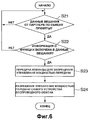
Фиг. 5 изображает последовательность операций для объяснения работы устройства беспроводной связи согласно второму варианту осуществления;FIG. 5 is a flowchart for explaining an operation of a wireless communication apparatus according to a second embodiment;
Фиг. 6 изображает последовательность операций для объяснения обработки в главном устройстве системы беспроводной связи согласно второму варианту осуществления;FIG. 6 is a flowchart for explaining processing in a host device of a wireless communication system according to a second embodiment;
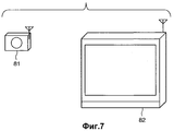
Фиг. 7 изображает вид, иллюстрирующий конфигурацию системы беспроводной связи, включающей в себя устройства беспроводной связи согласно третьему варианту осуществления настоящего изобретения;FIG. 7 is a view illustrating a configuration of a wireless communication system including wireless communication devices according to a third embodiment of the present invention;
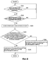
Фиг. 8 изображает последовательность операций для объяснения обработки в устройстве беспроводной связи согласно третьему варианту осуществления;FIG. 8 is a flowchart for explaining processing in a wireless communication apparatus according to a third embodiment;
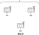
Фиг. 9 изображает вид, иллюстрирующий конфигурацию системы беспроводной связи, включающей в себя устройства беспроводной связи согласно четвертому варианту осуществления настоящего изобретения;FIG. 9 is a view illustrating a configuration of a wireless communication system including wireless communication devices according to a fourth embodiment of the present invention;
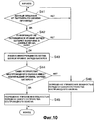
Фиг. 10 изображает последовательность операций для объяснения обработки в устройстве беспроводной связи согласно четвертому варианту осуществления;FIG. 10 is a flowchart for explaining processing in a wireless communication apparatus according to a fourth embodiment;
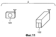
Фиг. 11 изображает вид, иллюстрирующий конфигурацию системы беспроводной связи, включающей в себя устройства беспроводной связи согласно пятому варианту осуществления настоящего изобретения;FIG. 11 is a view illustrating a configuration of a wireless communication system including wireless communication devices according to a fifth embodiment of the present invention;
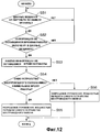
Фиг. 12 изображает последовательность операций для объяснения обработки в устройстве беспроводной связи согласно пятому варианту осуществления;FIG. 12 is a flowchart for explaining processing in a wireless communication apparatus according to a fifth embodiment;
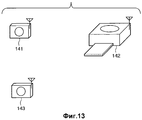
Фиг. 13 изображает вид, иллюстрирующий конфигурацию системы беспроводной связи, включающей в себя устройства беспроводной связи согласно шестому варианту осуществления настоящего изобретения;FIG. 13 is a view illustrating a configuration of a wireless communication system including wireless communication devices according to a sixth embodiment of the present invention;
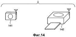
Фиг. 14 изображает вид, иллюстрирующий состояние, в котором устройства беспроводной связи (устройство ввода изображения и устройство вывода изображения) согласно шестому варианту осуществления находятся в специальном состоянии обмена; иFIG. 14 is a view illustrating a state in which wireless communication devices (image input device and image output device) according to the sixth embodiment are in a special exchange state; and
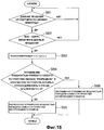
Фиг. 15 изображает последовательность операций для объяснения обработки в устройстве беспроводной связи согласно шестому варианту осуществления.FIG. 15 is a flowchart for explaining processing in a wireless communication apparatus according to a sixth embodiment.
Описание вариантов осуществленияDescription of Embodiments
Предпочтительные варианты осуществления настоящего изобретения описаны ниже подробно со ссылками на сопроводительные чертежи. Нижеследующие варианты осуществления не ограничивают формулу изобретения настоящего изобретения, и не все комбинации признаков, описанных в вариантах осуществления, являются существенными для средств решения согласно настоящему изобретению.Preferred embodiments of the present invention are described below in detail with reference to the accompanying drawings. The following embodiments do not limit the claims of the present invention, and not all combinations of features described in the embodiments are essential for the solution means of the present invention.
<Первый вариант осуществления><First Embodiment>
Конфигурация системы беспроводной связи, включающей в себя устройства беспроводной связи согласно первому варианту осуществления настоящего изобретения, описана ниже со ссылками на фиг. 1.A configuration of a wireless communication system including wireless communication devices according to a first embodiment of the present invention is described below with reference to FIG. one.
Фиг. 1 изображает вид, иллюстрирующий конфигурацию системы беспроводной связи согласно первому варианту осуществления настоящего изобретения.FIG. 1 is a view illustrating a configuration of a wireless communication system according to a first embodiment of the present invention.
Эта система беспроводной связи является системой беспроводной локальной сети в специальном режиме. На фиг. 1 ссылочные позиции 1 и 2 обозначают устройства беспроводной связи (беспроводные терминалы). В первом варианте осуществления беспроводным терминалом 1 является цифровая камера (устройство ввода изображения), и беспроводный терминал 2 является принтером (устройством вывода изображения).This wireless communication system is a wireless LAN system in a special mode. In FIG. 1, reference numerals 1 and 2 indicate wireless communication devices (wireless terminals). In the first embodiment, the wireless terminal 1 is a digital camera (image input device), and the wireless terminal 2 is a printer (image output device).
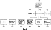
Фиг. 2 изображает блок-схему для объяснения функциональной конфигурации, осуществляющей функции, относящиеся к беспроводной связи и установкам для беспроводной связи в устройствах 1 и 2 беспроводной связи согласно первому варианту осуществления.FIG. 2 is a block diagram for explaining a functional configuration implementing functions related to wireless communication and settings for wireless communication in wireless communication devices 1 and 2 according to the first embodiment.
После приема радиоданных антенна 301 захватывает радиосигнал. Радиочастотная схема 302 преобразовывает радиосигнал в сигнал основной полосы частот. Процессор 303 основной полосы частот (полосы модулирующих частот) преобразует преобразованный сигнал основной полосы частот в цифровой сигнал. Цифровой сигнал преобразуют в заранее определенный формат данных в контроллере 304 доступа к среде и посылают на контроллер 305. Следует заметить, что, когда передают радиоданные, данные передаются в противоположном направлении.After receiving the radio data, the
Контроллер 305 сохраняет данные от контроллера 304 доступа к среде в памяти 306 или посылает эти данные через блок 307 интерфейса на внешнее устройство или блок (не показан), связанный с блоком 307 интерфейса. Контроллер 305 принимает данные от внешнего устройства или блока, связанного с блоком 307 интерфейса, и сохраняет данные в памяти 306 или посылает данные к контроллеру 304 доступа к среде. Контроллер 305 выдает данные, сохраненные в памяти 306, к контроллеру 304 доступа к среде или посылает данные на внешнее устройство или блок через блок 307 интерфейса. Контроллер 305 выполняет различные обработки данных и выводит и отображает результирующие данные на блоке 308 отображения. Устройство 309 ввода включает в себя клавиатуру и устройство указания и используется для различных установок, заданных пользователем, или для ввода команд. Контроллер 310 электроэнергии управляет мощностью передачи в беспроводном терминале в соответствии с командами контроллера 305 для выполнения управления сохранением энергии для снижения потребляемой мощности устройства. Следует заметить, что, хотя регулирование мощностью передачи объясняется в настоящем описании, может быть выполнено другое управление сохранением энергии, например, прием (команд) регулирования мощности и регулирование мощностью передачи/приема. Контроллер 310 электроэнергии может быть реализован аппаратно или с помощью аппаратных средств и программного обеспечения.The
Система беспроводной связи, использующая устройства 1 и 2 беспроводной связи согласно первому варианту осуществления, работает следующим образом.A wireless communication system using wireless communication devices 1 and 2 according to the first embodiment operates as follows.
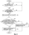
Фиг. 3 изображает последовательность операций для объяснения работы устройств 1 и 2 беспроводной связи согласно первому варианту осуществления.FIG. 3 is a flowchart for explaining the operation of the wireless communication devices 1 and 2 according to the first embodiment.
Во время выполнения обработки пользователь устанавливает режим работы каждого устройства 1 беспроводной связи, таких как цифровой камеры (устройства ввода изображения) и устройства 2 беспроводной связи в качестве принтера (устройства вывода изображения), в специальный режим (который разрешает непосредственную связь между беспроводными терминалами без точки доступа). Пользователь затем устанавливает SSID (идентификатор набора услуг) в качестве сетевого идентификатора и настройки (параметры) защиты равным заранее определенным значениям, чтобы обеспечить возможность обмена для устройств в специальном режиме.During processing, the user sets the operation mode of each wireless device 1, such as a digital camera (image input device) and wireless device 2 as a printer (image output device), to a special mode (which allows direct communication between wireless terminals without a point access). The user then sets the SSID (service set identifier) as the network identifier and security settings (parameters) to predefined values to allow exchange for devices in a special mode.
Каждое из устройств 1 и 2 беспроводной связи передает информацию о типе устройства под управлением соответствующего контроллера 305. Более конкретно, каждое из устройств 1 и 2 беспроводной связи передает информацию о типе устройства в качестве данных радиовещания приблизительно каждые 200 мс.Each of the wireless communication devices 1 and 2 transmits device type information under the control of a
Контроллер 305 каждого из устройств 1 и 2 беспроводной связи принимает данные радиовещания от партнера по обмену на этапе S1. На этапе S2 контроллер 305 определяет, включают ли в себя принятые данные информацию о типе устройства. Если данные не включают в себя информацию о типе устройства, процесс возвращается на этап S1; иначе процесс переходит на этап S3, чтобы анализировать принятую информацию о типе устройства.The
Таким образом, устройство 1 беспроводной связи в качестве устройства ввода изображения распознает, что устройство 2 беспроводной связи в качестве его партнера по обмену является устройством вывода изображения. Таким образом, устройство 1 беспроводной связи определяет "ДА" на этапе S4, и процесс переходит на этап S5. На этапе S5 контроллер 305 устройства 1 беспроводной связи разрешает управление электропитанием своего собственного контроллера 310 электроэнергии на основе его информации о типе устройства (устройства ввода изображения) и информации (устройства вывода изображения) его партнера по обмену.Thus, the wireless communication device 1 as an image input device recognizes that the wireless communication device 2 as its exchange partner is an image output device. Thus, the wireless communication device 1 determines “YES” in step S4, and the process proceeds to step S5. In step S5, the
Кроме того, устройство беспроводной связи 2 в качестве устройства ввода изображения определяет, что его партнером по обмену является устройство вывода изображения на этапе S4. Так как условие этапа S4 не выполнено, процесс переходит на этап S6. На этапе S6 контроллер 305 устройства 2 беспроводной связи запрещает управление электропитанием своего контроллера 310 электроэнергии на основе его информации о типе устройства (устройства вывода изображения) и информации (устройства ввода изображения ) его партнера 1 по обмену.In addition, the wireless communication device 2, as the image input device, determines that its image exchange partner is the image output device in step S4. Since the condition of step S4 is not fulfilled, the process proceeds to step S6. In step S6, the
Это разрешает устройству 1 беспроводной связи выполнять управление сохранением энергии, используя контроллер 310 электроэнергии. Так как только устройство 1 беспроводной связи управляет электропитанием, возможно поддерживать специальную сеть, способную к корректному обмену. Следует заметить, что в вышеупомянутом описании в случае, когда определено на этапе S2, что принятые данные не включают в себя информацию о типе устройства, процесс возвращается на этап S1. Однако, в случае, когда определено, что принятые данные не включают в себя информацию о типе устройства, управление электропитанием своего контроллера 310 электроэнергии может быть запрещено. Это имеет место потому, что неизвестно, как выполняется управление электропитанием устройства-партнера.This allows the wireless communication device 1 to perform energy conservation control using the
<Второй вариант осуществления><Second Embodiment>
Второй вариант осуществления настоящего изобретения описан ниже.A second embodiment of the present invention is described below.
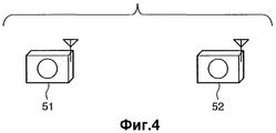
Фиг. 4 изображает вид, иллюстрирующий конфигурацию системы беспроводной связи, включающей устройство беспроводной связи согласно второму варианту осуществления настоящего изобретения.FIG. 4 is a view illustrating a configuration of a wireless communication system including a wireless communication device according to a second embodiment of the present invention.
Система беспроводной связи является системой беспроводной локальной сети в специальном режиме. На фиг. 4 ссылочные позиции 51 и 52 обозначают устройства беспроводной связи. Во втором варианте осуществления беспроводными терминалами 51 и 52 являются цифровые камеры (устройства ввода изображения). Следует заметить, что функциональные блоки, относящиеся к беспроводной связи и установкам для беспроводной связи в этих устройствах беспроводной связи, являются такими же, как на фиг. 2, описанной выше в первом варианте осуществления, и их описание будет опущено.A wireless communication system is a wireless LAN system in a special mode. In FIG. 4,
Система беспроводной связи, использующая устройства 51 и 52 беспроводной связи согласно второму варианту осуществления, работает следующим образом.A wireless communication system using
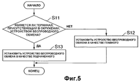
Фиг. 5 изображает последовательность операций для пояснения работы устройств 51 и 52 беспроводной связи согласно второму варианту осуществления.FIG. 5 is a flowchart for explaining the operation of
Пользователь устанавливает операционный режим (режим работы) каждого из устройств 51 и 52 беспроводной связи в специальный режим и устанавливает SSID и параметр защиты равным заранее определенным значениям, чтобы сделать устройства способными к специальному обмену.The user sets the operational mode (operation mode) of each of the
Обработка, показанная в последовательности операций согласно фиг. 5, выполняется активизированным устройством 51 беспроводной связи, то есть устройством 51 беспроводной связи. Устройство 51 беспроводной связи определяет на этапе S11, присутствует ли терминал в его окружении. Это определение делается на основе того, принимает ли устройство 51 беспроводной связи данные радиовещания, такие как сигнал радиомаяка, в течение некоторого периода времени. Если устройство 51 беспроводной связи не принимает сигнал, такой как сигнал радиомаяка, оно определяет, что вокруг него беспроводный терминал отсутствует. Процесс переходит на этап S12, чтобы установить устройство 51 беспроводной связи в качестве главного (ведущего). Аналогично, устройство S2 беспроводной связи, активизированное позднее, подтверждает на этапе S11, присутствует ли терминал вокруг него. В этом случае, так как устройство 51 беспроводной связи уже было активизировано, устройство 52 беспроводной связи принимает сигнал радиомаяка, переданный устройством 51 беспроводной связи. Таким образом, устройство 52 беспроводной связи определяет, что беспроводный терминал присутствует в его окружении. Процесс переходит на этап S13, чтобы установить устройство 52 беспроводной связи в качестве подчиненного.The processing shown in the flowchart of FIG. 5 is performed by the activated
После того как устройства 51 и 52 беспроводной связи активизированы, каждое из устройств 51 и 52 беспроводной связи передает функциональную информацию о самом себе под управлением соответствующего контроллера 305. Более конкретно, каждое из устройств 51 и 52 беспроводной связи передает в качестве данных радиовещания приблизительно каждые 150 мс информацию, указывающую, что устройство имеет функцию разрешения или запрещения управления электропитанием. Это разрешает каждому устройству беспроводной связи подтверждать, что терминал присутствует вокруг него.After the
Устройство 51 беспроводной связи является главным и поэтому работает так, как показано в последовательности операций согласно фиг. 6.The
Фиг. 6 изображает последовательность операций для объяснения обработки в главном устройстве системы беспроводной связи согласно второму варианту осуществления.FIG. 6 is a flowchart for explaining processing in a host device of a wireless communication system according to a second embodiment.
На этапе S21 устройство 51 беспроводной связи ожидает приема радиовещательных данных от своего партнера по обмену. Когда устройство 51 беспроводной связи принимает данные, процесс переходит на этап S22, чтобы определить, включают ли в себя принятые данные функциональную информацию. Если принятые данные включают в себя функциональную информацию, процесс переходит на этап S23, чтобы определить, имеет ли устройство 52 беспроводной связи функцию разрешения или запрещения управления электропитанием. На этапе S23 устройство 51 беспроводной связи посылает устройству 52 беспроводной связи (подчиненному) команды, чтобы отключить управление электропитанием. На этапе S24 устройство 51 беспроводной связи разрешает управление электропитанием своего собственного контроллера 310 электроэнергии (устройства 51 беспроводной связи (главного)).In step S21, the
Контроллер 305 устройства 52 беспроводной связи в качестве подчиненного отключает управление электропитанием своего собственного контроллера 310 электроэнергии на основе команды, переданной на этапе S23. Это разрешает только устройству 51 беспроводной связи в качестве главного выполнять управление сохранением энергии, используя контроллер 310 электроэнергии.The
Следует заметить, что в вышеупомянутом описании главное устройство разрешает управление электропитанием своего собственного контроллера 310 электроэнергии, и подчиненное устройство запрещает управление электропитанием своего собственного контроллера 310 электроэнергии. Однако главное устройство может отключать управление электропитанием своего собственного контроллера 310 электроэнергии, и подчиненное устройство может разрешать управление электропитанием своего собственного контроллера 310 электроэнергии.It should be noted that in the above description, the master device allows power control of its
Как описано выше, в системе беспроводной связи согласно второму варианту осуществления только одно устройство беспроводной связи управляет электропитанием. Поэтому возможно поддерживать специальную сеть, способную выполнять корректный обмен, в то же время избегая отказа в связи и увеличения потребляемой мощности из-за чрезмерно большой или маленькой мощности передачи каждого беспроводного терминала.As described above, in the wireless communication system according to the second embodiment, only one wireless communication device controls power supply. Therefore, it is possible to maintain a special network capable of performing the correct exchange, while at the same time avoiding communication failure and increasing power consumption due to the excessively large or small transmission power of each wireless terminal.
<Третий вариант осуществления><Third Embodiment>
Третий вариант осуществления настоящего изобретения описан ниже.A third embodiment of the present invention is described below.
Фиг. 7 изображает вид, иллюстрирующий конфигурацию системы беспроводной связи, включающей в себя устройства беспроводной связи, согласно третьему варианту осуществления настоящего изобретения.FIG. 7 is a view illustrating a configuration of a wireless communication system including wireless communication devices according to a third embodiment of the present invention.
Система беспроводной связи является системой беспроводной локальной сети в специальном режиме. На фиг. 7 ссылочные позиции 81 и 82 обозначают устройства беспроводной связи. Функциональные блоки, относящиеся к беспроводной связи, и установки для беспроводной связи в устройствах 81 и 82 беспроводной связи являются такими же, как на фиг. 2, описанной выше в первом варианте осуществления. В третьем варианте осуществления устройством 81 беспроводной связи является цифровая камера (устройство ввода изображения), а устройством 82 беспроводной связи является телевизор (устройство вывода изображения).A wireless communication system is a wireless LAN system in a special mode. In FIG. 7,
Система беспроводной связи, использующая устройства 81 и 82 беспроводной связи согласно третьему варианту осуществления, работает следующим образом.A wireless communication system using
Пользователь устанавливает операционный режим каждого из устройства 81 беспроводной связи в качестве устройства, относящегося к типу устройств с батарейным питанием, и устройства 82 беспроводной связи в качестве устройства, относящегося к типу устройств с промышленным источником питания, в специальный режим. Пользователь затем устанавливает SSID и параметр защиты равными заранее определенным значениям, чтобы установить специальный режим обмена между устройствами. После этого каждое из устройств 81 и 82 беспроводной связи передает свою информацию о типе источника питания на основании управления соответствующего контроллера 305. Более конкретно, каждое из устройств 81 и 82 беспроводной связи передает информацию о типе источника питания в качестве данных радиовещания приблизительно каждые 250 мс.The user sets the operating mode of each of the
Фиг. 8 изображает последовательность операций, объясняющую обработку устройств 81 и 82 беспроводной связи согласно третьему варианту осуществления.FIG. 8 is a flowchart for explaining the processing of
Когда контроллер 305 каждого из устройств 81 и 82 беспроводной связи принимает данные радиовещания от своего партнера по обмену на этапе S31, процесс переходит на этап S32, чтобы определить, включают ли в себя принятые данные информацию о типе источника питания. Если принятые данные включают в себя информацию о типе источника питания, процесс переходит на этап S33, чтобы проанализировать информацию о типе источника питания. Если на этапе S31 или S32 результатом является НЕТ, процесс возвращается на этап S31, чтобы повторить описанную выше обработку.When the
Устройство 81 беспроводной связи в качестве устройства с батарейным питанием распознает, что устройство 81 беспроводной связи само имеет тип с батарейным питанием, и беспроводный терминал в качестве партнера по обмену относится к типу устройств с промышленным источником питания. Поэтому процесс переходит на этап S35 от этапа S34. На этапе S35 контроллер 305 устройства 81 беспроводной связи разрешает управление электропитанием своего контроллера 310 электроэнергии на основе информации о типе источника питания (тип с батарейным питанием) и информации о типе источника питания (тип, относящийся к питанию от промышленного источника питания) его партнера по связи. Это имеет место потому, что питаемое от промышленного источника питания устройство не должно выполнять управление для снижения потребляемой мощности.The
Кроме того, устройство 82 беспроводной связи в качестве устройства, питаемого промышленным источником питания, подтверждает на этапе S34, что его партнер по обмену имеет тип с батарейным питанием. Процесс переходит на этап S36. На этапе S36 контроллер 305 устройства 82 беспроводной связи запрещает (отключает) управление электропитанием своего контроллера 310 электроэнергии на основе информации о типе источника питания (тип, питаемый промышленным источником питания) и информации о типе источника питания (тип с батарейным питанием) его партнера по связи.In addition, the
Это разрешает устройству беспроводной связи 81 выполнять управление сохранением энергии контроллера 310 электроэнергии. В этой системе, так как только одно устройство беспроводной связи выполняет управление электропитанием, возможно поддерживать специальную сеть, способную выполнять корректный обмен, в то же время избегая отказы в связи.This allows the
<Четвертый вариант осуществления><Fourth Embodiment>
Четвертый вариант осуществления настоящего изобретения описан ниже.A fourth embodiment of the present invention is described below.
Фиг. 9 изображает вид, иллюстрирующий конфигурацию системы беспроводной связи, включающей в себя устройства беспроводной связи согласно четвертому варианту осуществления настоящего изобретения.FIG. 9 is a view illustrating a configuration of a wireless communication system including wireless communication devices according to a fourth embodiment of the present invention.
Система беспроводной связи является системой беспроводной локальной сети в специальном режиме. На фиг. 9 ссылочные позиции 101-103 обозначают устройства беспроводной связи. Устройствами 101-103 беспроводной связи являются цифровые камеры (устройства ввода изображения). Функциональные блоки, относящиеся к беспроводной связи, и установки (параметры настройки) для беспроводной связи в устройствах 101-103 беспроводной связи являются такими же, как на фиг. 2, описанной выше в первом варианте осуществления.A wireless communication system is a wireless LAN system in a special mode. In FIG. 9, reference numerals 101-103 indicate wireless communication devices. Wireless communication devices 101-103 are digital cameras (image input devices). Functional blocks related to wireless communication and settings (settings) for wireless communication in wireless communication devices 101-103 are the same as in FIG. 2 described above in the first embodiment.
Фиг. 10 изображает последовательность операций для объяснения обработки в устройствах 101-103 беспроводной связи согласно четвертому варианту осуществления.FIG. 10 is a flowchart for explaining processing in wireless communication devices 101-103 according to a fourth embodiment.
Прежде чем обработка начинается, пользователь устанавливает операционный режим каждого из устройств 101, 102 и 103 беспроводной связи в специальный режим и устанавливает SSID и параметры настройки защиты равным заранее определенным значениям, чтобы сделать их способными к специальному обмену. После этого каждое из устройств 101, 102 и 103 беспроводной связи передает свою информацию об оставшемся уровне заряда батареи под управлением соответствующего контроллера 305. Более конкретно, каждое из устройств 101, 102 и 103 беспроводной связи передает информацию оставшегося уровня батареи своей собственной батареи в качестве данных радиовещания приблизительно каждые 750 мс.Before processing begins, the user sets the operational mode of each of the
На основании этих предположений, когда контроллер 305 каждого из устройств 101, 102 и 103 беспроводной связи принимает данные радиовещания на этапе S41, процесс переходит на этап S42, чтобы определить, включают ли в себя эти данные информацию об оставшемся уровне батареи каждой собственной батареи. Если данные не включают в себя такую информацию, процесс возвращается на этап S41, иначе процесс переходит на этап S43, чтобы проанализировать информацию.Based on these assumptions, when the
На этапе S44 контроллер 305 каждого из устройств 101, 102 и 103 беспроводной связи определяет, имеет ли соответствующее устройство беспроводной связи наименьший оставшийся уровень батарей среди устройств 101, 102 и 103. Если уровень батарей соответствующего устройства беспроводной связи является наименьшим оставшимся уровнем батарей, процесс переходит на этап S45, чтобы разрешить управление электропитанием своего собственного контроллера 310 электроэнергии; иначе процесс переходит на этап S46, чтобы отключить управление электропитанием своего собственного контроллера 310 электроэнергии.In step S44, the
Это разрешает только устройству беспроводной связи, имеющему наименьший оставшийся уровень батарей, выполнять управление сохранением энергии контроллера 310 электроэнергии. В этой системе беспроводной связи, так как только одно устройство беспроводной связи управляет электропитанием, возможно поддерживать специальную сеть, способную выполнять корректный обмен, в то же время избегая отказы в связи.This allows only the wireless device having the smallest remaining battery level to perform energy management control of the
<Пятый вариант осуществления><Fifth Embodiment>
Пятый вариант осуществления настоящего изобретения описан ниже.A fifth embodiment of the present invention is described below.
Фиг. 11 изображает вид, иллюстрирующий конфигурацию системы беспроводной связи, включающей в себя устройства беспроводной связи согласно пятому варианту осуществления настоящего изобретения.FIG. 11 is a view illustrating a configuration of a wireless communication system including wireless communication devices according to a fifth embodiment of the present invention.
Система беспроводной связи является системой беспроводной локальной сети в специальном режиме. На фиг. 11 ссылочные позиции 121 и 122 обозначают устройства беспроводной связи. В пятом варианте осуществления устройство 121 беспроводной связи является цифровой камерой (устройством ввода изображения), и устройство 122 беспроводной связи является запоминающим устройством (устройством хранения изображения). Функциональные блоки, относящиеся к беспроводной связи, и параметры настройки для беспроводной связи в устройствах 121 и 122 беспроводной связи являются такими же, как на фиг. 2, описанными выше в первом варианте осуществления.A wireless communication system is a wireless LAN system in a special mode. In FIG. 11,
Фиг. 12 изображает последовательность операций, объясняющую обработку в устройствах 121 и 122 беспроводной связи согласно пятому варианту осуществления.FIG. 12 is a flowchart for explaining processing in
Пользователь устанавливает операционный режим каждого из устройства 121 беспроводной связи как устройства ввода изображения и устройства 122 беспроводной связи в качестве устройства хранения изображения в специальный режим и устанавливает SSID и параметры настройки защиты равным заранее определенным значениям, чтобы дать возможность устройствам обмениваться в специальном режиме.The user sets the operational mode of each of the
Под управлением контроллера 305 каждое из устройств 121 и 122 беспроводной связи передает информацию о своем оставшемся периоде времени работы. Более конкретно, каждое из устройств 121 и 122 беспроводной связи передает информацию о своем оставшемся периоде времени работы в качестве данных радиовещания приблизительно каждые 500 мс. В пятом варианте осуществления оставшийся период времени работы может быть определен в соответствии с оставшимся уровнем батарей каждого устройства беспроводной связи. Однако, если, например, действительный период времени установлен для устройства, оставшийся период времени работы может быть определен в соответствии с фактическим оставшимся периодом времени.Under the control of
На этапе S51, когда контроллер 305 каждого из устройств 121 и 122 беспроводной связи принимает данные радиовещания от своего партнера по обмену, процесс переходит на этап S52. На этапе S52 контроллер 305 определяет, включают ли данные в себя информацию об оставшемся периоде времени работы. Если данные включают в себя информацию об оставшемся периоде времени работы, процесс переходит на этап S53, чтобы проанализировать информацию.In step S51, when the
На этапе S54 контроллер 305 каждого из устройств 121 и 122 беспроводной связи определяет, имеет ли устройство наименьший оставшийся период времени работы, анализируя информацию и подтверждая свой собственный оставшийся период времени работы. Если соответствующее устройство беспроводной связи имеет наименьший оставшийся период времени работы, процесс переходит на этап S55, чтобы разрешить управление электропитанием своего собственного контроллера 310 электроэнергии, иначе процесс переходит на этап S56, чтобы отключить управление электропитанием своего собственного контроллера 310 электроэнергии.In step S54, the
Это разрешает только устройству беспроводной связи, имеющему наименьший оставшийся период времени работы (например, наименьший оставшийся уровень батарей), выполнять управление сохранением энергии. То есть, так как только одно устройство беспроводной связи, имеющее наименьший оставшийся период времени работы, управляет электропитанием, возможно поддерживать специальную сеть, способную выполнять корректный обмен, в то же время избегая отказа в связи.This allows only the wireless device having the smallest remaining battery life (for example, the smallest remaining battery level) to perform energy conservation control. That is, since only one wireless communication device having the smallest remaining operating time period controls the power supply, it is possible to support a special network capable of performing a correct exchange while avoiding communication failure.
<Шестой вариант осуществления><Sixth Embodiment>
Шестой вариант осуществления настоящего изобретения описан ниже.A sixth embodiment of the present invention is described below.
Фиг. 13 изображает вид, иллюстрирующий конфигурацию системы беспроводной связи, включающей в себя устройства беспроводной связи, согласно шестому варианту осуществления настоящего изобретения.FIG. 13 is a view illustrating a configuration of a wireless communication system including wireless communication devices according to a sixth embodiment of the present invention.
Конфигурация системы беспроводной связи, включающей в себя устройства беспроводной связи согласно шестому варианту осуществления, описана со ссылками на фиг. 13. Система беспроводной связи является системой беспроводной локальной сети в специальном режиме. На фиг. 13 ссылочные позиции 141-143 обозначают устройства беспроводной связи. В шестом варианте осуществления устройства 141 и 143 беспроводной связи являются цифровыми камерами (устройствами ввода изображения), и устройство 142 беспроводной связи является принтером (устройством вывода изображения). Функциональные блоки, относящиеся к беспроводной связи, и параметры настройки для беспроводной связи в этих устройствах 141-143 беспроводной связи являются теми же, как на фиг. 2, описанные выше в первом варианте осуществления.A configuration of a wireless communication system including wireless communication devices according to a sixth embodiment is described with reference to FIG. 13. A wireless communication system is a wireless LAN system in a special mode. In FIG. 13, reference numerals 141-143 indicate wireless communication devices. In a sixth embodiment, the
Пользователь устанавливает операционный режим каждого устройства 141 беспроводной связи в качестве устройства ввода изображения и устройства 142 беспроводной связи в качестве устройства вывода изображения в специальный режим и устанавливает SSID и параметры настройки защиты равным заранее определенным значениям, чтобы обеспечить их обмен в специальном режиме.The user sets the operating mode of each
Фиг. 14 изображает вид, иллюстрирующий состояние, в котором устройства беспроводной связи (устройство ввода изображения и устройство вывода изображения) согласно шестому варианту осуществления находятся в специальном состоянии обмена.FIG. 14 is a view illustrating a state in which the wireless communication devices (image input device and image output device) according to the sixth embodiment are in a special exchange state.
В этом случае, выполняя те же самые операции, как в первом-пятом вариантах осуществления, описанных выше, устройство 141 беспроводной связи разрешает управление электропитанием своего собственного контроллера 310 электроэнергии, и устройство 142 беспроводной связи отключает управление электропитанием своего собственного контроллера 310 электроэнергии.In this case, by performing the same operations as in the first to fifth embodiments described above, the
После этого пользователь устанавливает операционный режим устройства 143 беспроводной связи в качестве устройства ввода изображения в специальный режим и устанавливает SSID и параметры настройки защиты равным заранее определенным значениям. Таким образом, устройство 143 беспроводной связи подсоединяется к специальной сети. Под управлением своего собственного контроллера 305, как только источник питания каждого из устройств 141, 142 и 143 беспроводной связи включен, каждое устройство передает информацию о своем устройстве. Более конкретно, каждое из устройств 141, 142 и 143 беспроводной связи передает свой MAC (Управление доступом к среде) адрес в качестве данных радиовещания приблизительно каждые 100 мс.After that, the user sets the operating mode of the
Фиг. 15 изображает последовательность операций, поясняющую обработку в устройствах 141, 142 и 143 беспроводной связи согласно шестому варианту осуществления настоящего изобретения.FIG. 15 is a flowchart for explaining processing in
Когда контроллер 305 каждого из устройств 141, 142 и 143 беспроводной связи принимает данные радиовещания на этапе S61, процесс переходит на этап S62. На этапе S62 контроллер 305 определяет, включают ли в себя принятые данные MAC адрес. Если принятые данные включают в себя MAC адрес, процесс переходит на этап S63, чтобы проанализировать информацию.When the
Анализируя информацию и подтверждая свой собственный MAC адрес на этапе S63, контроллер 305 каждого из устройств 141, 142 и 143 беспроводной связи распознает количество устройств беспроводной связи, которые присоединились к специальной сети. На этапе S64 контроллер 305 определяет, является ли количество устройств беспроводной связи, которые присоединились к специальной сети, равным "2". Если это количество устройств равно "2", и определено, что управление электропитанием посредством своего собственного контроллера 310 электроэнергии должно быть разрешено в соответствии с любым из с первого по пятый варианты осуществления, то процесс переходит на этап S65, чтобы разрешить управление электропитанием своего собственного контроллера 310 электроэнергии. Если количество устройств не равно "2", или на этапе S64 определено, что управление электропитанием посредством своего собственного контроллера 310 электроэнергии должно быть разрешено в соответствии с любым из с первого по пятый варианты осуществления, то процесс переходит на этап S66, чтобы отключить управление электропитанием своего собственного контроллера 310 электроэнергии.By analyzing the information and confirming its own MAC address in step S63, the
Как описано выше, согласно шестому варианту осуществления каждое из устройств 142 и 143 беспроводной связи отключает управление электропитанием. Это дает возможность запретить двум или более устройствам беспроводной связи управлять электропитанием. Поэтому возможно поддерживать специальную сеть, способную выполнять корректный обмен, в то же время избегая отказа в связи.As described above, according to the sixth embodiment, each of the
<Другие варианты осуществления><Other Embodiments>
Варианты осуществления настоящего изобретения были подробно описаны выше. Настоящее изобретение может применяться к системе, включающей в себя множество устройств, или аппаратуре, сформированной единственным устройством.Embodiments of the present invention have been described in detail above. The present invention can be applied to a system including a plurality of devices or apparatus formed by a single device.
Настоящее изобретение также реализуется, обеспечивая программу, реализующую функции описанных выше вариантов осуществления, для системы или устройства непосредственно или от удаленного места, и считыванием и выполнением подаваемой программы компьютером системы или устройством. В этом случае форма настоящего изобретения не должна быть программой до тех пор, пока обеспечиваются функциональные возможности программы.The present invention is also implemented by providing a program that implements the functions of the above embodiments for a system or device directly or from a remote location, and reading and executing the program supplied by the computer of the system or device. In this case, the form of the present invention should not be a program as long as the functionality of the program is provided.
Настоящее изобретение, поэтому, осуществлено программными кодами, установленными в компьютере, чтобы реализовать компьютером функциональные процессы настоящего изобретения. То есть формула изобретения настоящего изобретения включает в себя компьютерную программу для осуществления функциональных процессов настоящего изобретения. В этом случае форма программы является произвольной, например, объектный код, программа, выполняемая интерпретатором, или данные сценария, поданные в ОС, пока она обеспечивает функциональные возможности программы.The present invention, therefore, is implemented by program codes installed in a computer in order to implement the functional processes of the present invention by a computer. That is, the claims of the present invention include a computer program for implementing the functional processes of the present invention. In this case, the form of the program is arbitrary, for example, object code, a program executed by the interpreter, or script data submitted to the OS while it provides the functionality of the program.
В качестве носителя записи для поставки программы могут использоваться, например, дискета, жесткий диск, оптический диск, магнитооптический диск, МО, CD-ROM, CD-R, CD-RW, магнитная лента, энергонезависимая плата с памятью, ROM и DVD (DVD-ПЗУ, DVD-R).As a recording medium for program delivery, for example, a floppy disk, hard disk, optical disk, magneto-optical disk, MO, CD-ROM, CD-R, CD-RW, magnetic tape, non-volatile memory card, ROM and DVD (DVD) can be used ROM, DVD-R).
В качестве другого способа поставки программы программа может быть доставлена посредством подключения клиентского компьютера к Web-странице сети Интернет через браузер клиентского компьютера и загрузки программы с Web-страницы на носитель записи, например жесткий диск. Загруженная программа может быть компьютерной программой согласно настоящему изобретению или сжатым файлом, содержащим функцию автоматической установки. Программа может также быть реализована, группируя программные коды, которые формируют программу согласно настоящему изобретению во множество файлов, и загружая файлы с различных Web-страниц. То есть формула изобретения настоящего изобретения также включает в себя WWW-сервер, который разрешает множеству пользователей загружать программные файлы для осуществления функциональных процессов настоящего изобретения, используя компьютер.As another method for delivering a program, the program can be delivered by connecting a client computer to an Internet web page through a client computer browser and downloading the program from the web page to a recording medium such as a hard disk. The downloaded program may be a computer program according to the present invention or a compressed file containing an automatic installation function. The program may also be implemented by grouping program codes that form the program of the present invention into a plurality of files, and downloading files from various web pages. That is, the claims of the present invention also include a WWW server that allows a plurality of users to download program files for carrying out the functional processes of the present invention using a computer.
Программа настоящего изобретения может быть зашифрована, сохранена на носителе записи типа CD-ROM и распределена пользователю. В этом случае пользователь, который удовлетворяет заранее определенным условиям, запрашивается для загрузки информации ключа расшифровки с Web-страницы через Интернет, и зашифрованная программа, используя эту информацию о ключе, может быть установлена в компьютер в выполнимой форме.The program of the present invention can be encrypted, stored on a CD-ROM type recording medium, and distributed to a user. In this case, a user who satisfies predetermined conditions is requested to download the decryption key information from the Web page via the Internet, and an encrypted program using this key information can be installed into the computer in an executable form.
Функции описанных выше вариантов осуществления реализуются, когда компьютер выполняет программу считывания. Также функции описанных выше вариантов осуществления реализуются, когда ОС или подобное средство, выполняемое на компьютере, исполняет некоторые или все действительные процессы на основе команд программы.The functions of the above embodiments are realized when the computer executes a reader program. Also, the functions of the above embodiments are realized when an OS or a similar tool running on a computer executes some or all of the actual processes based on program instructions.
Программа, считываемая с носителя записи, может быть записана в память платы расширения, вставленной в компьютер, или память модуля расширения функций, связанный с компьютером. В этом случае функции описанных выше вариантов осуществления реализуются, когда ЦП платы расширения или модуля расширения функций исполняет некоторые или все действительные процессы на основе команд программы, после того как программа записана в память платы расширения или память модуля расширения функций.A program read from a recording medium may be written to the memory of an expansion card inserted in a computer, or the memory of a function expansion module associated with a computer. In this case, the functions of the embodiments described above are realized when the CPU of the expansion card or expansion module executes some or all of the actual processes based on the instructions of the program after the program is written to the memory of the expansion card or the memory of the expansion module.
Хотя настоящее изобретение выше описано со ссылками на примерные варианты осуществления, должно быть понятно, что изобретение не ограничено раскрытыми примерными вариантами осуществления. Объем нижеследующей формулы изобретения должен сопровождаться самой широкой интерпретацией, чтобы охватить все такие модификации и эквивалентные структуры и функции.Although the present invention has been described above with reference to exemplary embodiments, it should be understood that the invention is not limited to the disclosed exemplary embodiments. The scope of the following claims should be followed by the broadest interpretation so as to encompass all such modifications and equivalent structures and functions.
Claims (16)
Applications Claiming Priority (2)
| Application Number | Priority Date | Filing Date | Title |
|---|---|---|---|
| JP2005380171A JP4684888B2 (en) | 2005-12-28 | 2005-12-28 | Communication apparatus and power control method |
| JP2005-380171 | 2005-12-28 |
Publications (1)
| Publication Number | Publication Date |
|---|---|
| RU2326498C1 true RU2326498C1 (en) | 2008-06-10 |
Family
ID=37949640
Family Applications (1)
| Application Number | Title | Priority Date | Filing Date |
|---|---|---|---|
| RU2006146040/09A RU2326498C1 (en) | 2005-12-28 | 2006-12-25 | Communication device and power supply control method |
Country Status (6)
| Country | Link |
|---|---|
| US (1) | US7818022B2 (en) |
| EP (1) | EP1804531B1 (en) |
| JP (1) | JP4684888B2 (en) |
| KR (1) | KR100820848B1 (en) |
| CN (1) | CN1992551B (en) |
| RU (1) | RU2326498C1 (en) |
Cited By (1)
| Publication number | Priority date | Publication date | Assignee | Title |
|---|---|---|---|---|
| MD3957G2 (en) * | 2006-01-31 | 2010-03-31 | Amperion, Inc. | Radio frequency coupler, coupling system and method |
Families Citing this family (18)
| Publication number | Priority date | Publication date | Assignee | Title |
|---|---|---|---|---|
| JP5036212B2 (en) | 2006-04-21 | 2012-09-26 | キヤノン株式会社 | Communication apparatus and transmission power control method thereof |
| JP4990067B2 (en) * | 2007-08-22 | 2012-08-01 | シャープ株式会社 | Wireless data communication system |
| EP2210242A4 (en) * | 2007-11-13 | 2012-04-18 | Spielo Mfg Ulc | Wireless wagering system |
| JP5455709B2 (en) * | 2010-02-26 | 2014-03-26 | キヤノン株式会社 | Management device, control method thereof, and program |
| JP2011215955A (en) * | 2010-03-31 | 2011-10-27 | Toshiba Corp | Communication system, communication equipment, and method of supplying electric power |
| JP5489228B2 (en) * | 2010-09-21 | 2014-05-14 | Necシステムテクノロジー株式会社 | Wireless connection setting device, wireless connection setting method, and wireless connection setting program |
| EP2506448B1 (en) * | 2011-03-28 | 2021-08-04 | Sony Group Corporation | Method and module for switching operating mode, and terminal equipment |
| CN102710296A (en) * | 2011-03-28 | 2012-10-03 | 索尼爱立信移动通讯有限公司 | Working mode switching method, working mode switching module and terminal equipment |
| JP5952416B2 (en) * | 2012-09-27 | 2016-07-13 | 京セラ株式会社 | Management method, control apparatus, and communication processing device |
| US8892104B1 (en) | 2012-10-26 | 2014-11-18 | Sprint Spectrum L.P. | Selective simultaneous communication with a wireless communication device based on device type |
| US8948746B1 (en) | 2012-10-26 | 2015-02-03 | Sprint Spectrum L.P. | Enabling an extent of substantially simultaneous communication based on device prevalence |
| WO2014104568A1 (en) * | 2012-12-27 | 2014-07-03 | Samsung Electronics Co., Ltd. | Host device, display device, method of controlling host device, and method of controlling display device |
| US20150296454A1 (en) * | 2014-04-15 | 2015-10-15 | Newracom, Inc. | Method for low-power communications in wireless local area network and apparatus for the same |
| KR102202691B1 (en) * | 2014-04-15 | 2021-01-12 | 뉴라컴 인코포레이티드 | Method for low power communication in wireless local area network and apparatus for the same |
| JP6379790B2 (en) * | 2014-07-23 | 2018-08-29 | 富士電機株式会社 | Wireless network system |
| CN104244373B (en) * | 2014-08-29 | 2017-12-19 | 苏州汉明科技有限公司 | A kind of method that wireless terminal adds wireless network |
| WO2021229587A1 (en) * | 2020-05-15 | 2021-11-18 | Telefonaktiebolaget Lm Ericsson (Publ) | Core network node and method in a wireless communications network |
| CN112511335B (en) * | 2020-11-02 | 2022-03-25 | 珠海格力电器股份有限公司 | IT equipment control method and device and data center management system |
Family Cites Families (45)
| Publication number | Priority date | Publication date | Assignee | Title |
|---|---|---|---|---|
| US6654378B1 (en) * | 1992-03-18 | 2003-11-25 | Broadcom Corp. | Transaction control system including portable data terminal and mobile customer service station |
| US5613135A (en) * | 1992-09-17 | 1997-03-18 | Kabushiki Kaisha Toshiba | Portable computer having dedicated register group and peripheral controller bus between system bus and peripheral controller |
| JP3202878B2 (en) * | 1994-09-19 | 2001-08-27 | 株式会社バーテックススタンダード | Transmission power saving method |
| SE9600578L (en) | 1996-02-16 | 1997-03-10 | Ericsson Telefon Ab L M | Method and apparatus for channel assignment in a radio communication system |
| JP2803626B2 (en) | 1996-04-05 | 1998-09-24 | 日本電気株式会社 | Transmission power control method for mobile radio terminals |
| JP2830911B2 (en) | 1996-06-07 | 1998-12-02 | 日本電気株式会社 | MOBILE COMMUNICATION SYSTEM, TRANSMISSION POWER CONTROL METHOD THEREOF, BASE STATION RADIO APPARATUS AND HIGHER STATION USED FOR THE SAME |
| FI104025B1 (en) | 1996-08-28 | 1999-10-29 | Nokia Telecommunications Oy | Power control method and cellular radio system |
| US5987326A (en) | 1997-02-11 | 1999-11-16 | Qualcomm Incorporated | Transmit power reduction for a high speed CDMA link in soft handoff |
| US6185432B1 (en) | 1997-10-13 | 2001-02-06 | Qualcomm Incorporated | System and method for selecting power control modes |
| US6708041B1 (en) | 1997-12-15 | 2004-03-16 | Telefonaktiebolaget Lm (Publ) | Base station transmit power control in a CDMA cellular telephone system |
| US6744754B1 (en) | 1998-06-09 | 2004-06-01 | Lg Information & Communications, Ltd. | Control of forward link power CDMA mobile communication system |
| US6587696B1 (en) | 1998-07-31 | 2003-07-01 | Nokia Mobile Phones Limited | Power control technique utilizing forward pilot channel |
| US6519236B1 (en) | 1998-09-18 | 2003-02-11 | Telefonaktiebolaget Lm Ericsson (Publ) | Automatic power control in uncoordinated frequency-hopping radio systems |
| JP2000101511A (en) | 1998-09-24 | 2000-04-07 | Fujitsu Ltd | Transmission level control method and transmitter- receiver in subscriber system radio access system |
| JP2000165290A (en) * | 1998-11-25 | 2000-06-16 | Futaba Corp | Spread spectrum communication method and spread spectrum communication device |
| US6377813B1 (en) | 1998-12-03 | 2002-04-23 | Nokia Corporation | Forward link closed loop power control for a third generation wideband CDMA system |
| EP1037396B1 (en) | 1999-03-16 | 2012-05-02 | Alcatel Lucent | A method for improving performances of a mobile radiocommunication system using a power control algorithm |
| US6697343B1 (en) * | 1999-08-26 | 2004-02-24 | Lucent Technologies Inc. | Method and apparatus for controlling power for variable-rate vocoded communications |
| US6563810B1 (en) | 1999-09-30 | 2003-05-13 | Qualcomm Incorporated | Closed loop resource allocation |
| JP3473555B2 (en) | 2000-06-30 | 2003-12-08 | 日本電気株式会社 | Transmission power control system, control method, base station, control station, and recording medium |
| JP3559757B2 (en) * | 2000-08-22 | 2004-09-02 | キヤノン株式会社 | Communication method and communication device |
| FR2813487B1 (en) * | 2000-08-31 | 2002-11-29 | Cit Alcatel | METHOD AND DEVICE FOR CONTROLLING THE AMPLIFICATION OF THE SIGNAL TRANSMITTED BY A MOBILE TERMINAL FOR INCREASING THE AUTONOMY OF SAID MOBILE TERMINAL |
| US6735448B1 (en) * | 2000-11-07 | 2004-05-11 | Hrl Laboratories, Llc | Power management for throughput enhancement in wireless ad-hoc networks |
| GB2369961B (en) | 2000-12-09 | 2003-04-23 | Ericsson Telefon Ab L M | Transmission control in a radio access network |
| KR100636527B1 (en) * | 2000-12-30 | 2006-10-18 | 주식회사 팬택앤큐리텔 | Apparatus and method for power management in bluetooth system |
| JP3610911B2 (en) | 2001-01-29 | 2005-01-19 | 日本電気株式会社 | Transmission power control method and transmission power control apparatus |
| JP2002290320A (en) * | 2001-03-28 | 2002-10-04 | Denso Corp | Bluetooth SYSTEM AND Bluetooth MOUNTED DEVICE |
| JP3929258B2 (en) | 2001-06-21 | 2007-06-13 | 富士通株式会社 | Power control apparatus and power control method for wireless communication |
| WO2003010903A1 (en) | 2001-07-24 | 2003-02-06 | Ntt Docomo, Inc. | Transmission power control apparatus and method in a mobile communication system, mobile station, and communication apparatus |
| JP3834492B2 (en) * | 2001-08-30 | 2006-10-18 | 株式会社ケンウッド | Battery saving method, mobile device, and battery saving processing program recording storage medium |
| JP3534099B2 (en) * | 2001-10-12 | 2004-06-07 | ミノルタ株式会社 | Imaging printing system, digital camera and printer |
| US7024230B2 (en) * | 2002-02-22 | 2006-04-04 | Kyocera-Wireless Corp | Accessory interface system |
| US6704584B2 (en) * | 2002-04-16 | 2004-03-09 | Thomson Licensing S.A. | Mechanism for a wireless device to relinquish its network master status based on its power reserve |
| JP2003347943A (en) | 2002-05-29 | 2003-12-05 | Alps Electric Co Ltd | Card type wireless lan |
| JP2003348010A (en) | 2002-05-29 | 2003-12-05 | Ntt Docomo Inc | Controller, mobile communication system and transmission power control method |
| JP3574443B2 (en) | 2002-08-20 | 2004-10-06 | 松下電器産業株式会社 | Communication terminal device, base station device, and transmission power control method |
| TWI333755B (en) * | 2002-11-15 | 2010-11-21 | Interdigital Tech Corp | Wireless transmit/receive units having multiple receivers and methods |
| US20040162804A1 (en) * | 2003-02-18 | 2004-08-19 | Michael Strittmatter | System and method for searching for wireless devices |
| AU2003209528A1 (en) * | 2003-02-27 | 2004-09-17 | Nokia Corporation | Method and device for activating bluetooth devices through signaling |
| JP4090373B2 (en) * | 2003-03-19 | 2008-05-28 | 日立マクセル株式会社 | Small electrical equipment |
| US7539507B2 (en) | 2003-11-21 | 2009-05-26 | Qualcomm Incorporated | Peer-to-peer communications |
| US7660605B2 (en) * | 2004-08-31 | 2010-02-09 | Research In Motion Limited | Method and system for the configuration of a mobile station baseband circuit for an acoustic accessory |
| JP2006087023A (en) | 2004-09-17 | 2006-03-30 | Toshiba Corp | Radio communication unit and information processing unit |
| KR20060066011A (en) * | 2004-12-11 | 2006-06-15 | 삼성전자주식회사 | Method for deciding operation of node in a mobile communication system and system thereof |
| US7660273B2 (en) | 2005-11-08 | 2010-02-09 | Via Technologies Inc. | WLAN data reception method and WLAN device |
-
2005
- 2005-12-28 JP JP2005380171A patent/JP4684888B2/en active Active
-
2006
- 2006-12-08 EP EP06025435.6A patent/EP1804531B1/en active Active
- 2006-12-14 US US11/610,580 patent/US7818022B2/en active Active
- 2006-12-22 KR KR1020060132395A patent/KR100820848B1/en not_active IP Right Cessation
- 2006-12-25 RU RU2006146040/09A patent/RU2326498C1/en active
- 2006-12-28 CN CN2006101703391A patent/CN1992551B/en active Active
Cited By (1)
| Publication number | Priority date | Publication date | Assignee | Title |
|---|---|---|---|---|
| MD3957G2 (en) * | 2006-01-31 | 2010-03-31 | Amperion, Inc. | Radio frequency coupler, coupling system and method |
Also Published As
| Publication number | Publication date |
|---|---|
| US20070149140A1 (en) | 2007-06-28 |
| EP1804531A1 (en) | 2007-07-04 |
| CN1992551B (en) | 2012-04-25 |
| KR100820848B1 (en) | 2008-04-11 |
| KR20070070075A (en) | 2007-07-03 |
| EP1804531B1 (en) | 2016-05-04 |
| JP4684888B2 (en) | 2011-05-18 |
| JP2007181144A (en) | 2007-07-12 |
| CN1992551A (en) | 2007-07-04 |
| US7818022B2 (en) | 2010-10-19 |
Similar Documents
| Publication | Publication Date | Title |
|---|---|---|
| RU2326498C1 (en) | Communication device and power supply control method | |
| EP1538792B1 (en) | Configuring a wireless communication device with setting information | |
| US7805493B2 (en) | Network service system, service proxy processing method, computer-readable storage medium storing program, and program therefor | |
| EP3193518B1 (en) | Wireless communication terminal, wireless communication system, and wireless communication program | |
| US20180324139A1 (en) | Communication apparatus and communication method therefor | |
| CN105322986A (en) | Function execution system, function execution device and communication terminal | |
| US8769064B2 (en) | System using wired interface to configure wireless connection between host and image forming device | |
| US9560116B2 (en) | Network device, system, method, and storage medium | |
| US20070073914A1 (en) | Wireless communication apparatus and control method of the apparatus | |
| CN105306768A (en) | Information processing apparatus and method of controlling the same | |
| US10091827B2 (en) | Electronic apparatus, method of supporting wireless connection, image forming apparatus, and method of wireless connection | |
| EP3291509B1 (en) | Information processing device and non-transitory recording medium | |
| JP2009110261A (en) | Network management apparatus, network management method, and program for carrying out network management method | |
| US11019622B2 (en) | Information processing apparatus and control method | |
| WO2018113113A1 (en) | Double-system terminal wifi sharing method and device | |
| JP2005136591A (en) | Method and program of setting communication environment | |
| CN103608771B (en) | Share and access to local device | |
| JP7059227B2 (en) | Information processing equipment, control methods and programs | |
| JP2020123798A (en) | Information processing device, wireless terminal and program | |
| JP2006035456A (en) | Image processor and its controlling method and program | |
| JP2019126083A (en) | Communication device and computer program for communication device | |
| CN113099445A (en) | Network configuration method, equipment connection method, device, equipment and system | |
| JP2001312432A (en) | Network server and its control method | |
| JP2022087295A (en) | Information processing device, control method, and program | |
| CN115190275A (en) | Network video recorder, video monitoring system and video monitoring method |