RU2287882C1 - Switchgear and control gear - Google Patents
Switchgear and control gear Download PDFInfo
- Publication number
- RU2287882C1 RU2287882C1 RU2005109354/09A RU2005109354A RU2287882C1 RU 2287882 C1 RU2287882 C1 RU 2287882C1 RU 2005109354/09 A RU2005109354/09 A RU 2005109354/09A RU 2005109354 A RU2005109354 A RU 2005109354A RU 2287882 C1 RU2287882 C1 RU 2287882C1
- Authority
- RU
- Russia
- Prior art keywords
- compartment
- cable
- switchgear
- draw
- current
- Prior art date
Links
Images
Landscapes
- Patch Boards (AREA)
Abstract
Description
Изобретение относится к области высоковольтного строения, в том числе к конструкциям шкафов распределительных устройств (далее КРУ) внутренней установки в металлической оболочке [1-3].The invention relates to the field of high-voltage structures, including the design of switchgear cabinets (hereinafter referred to as switchgear) of an indoor installation in a metal shell [1-3].
Известные КРУ, серийно выпускаемые, унифицированы выдвижными элементами с вакуумными и элегазовыми выключателями, предназначенными для приема и распределения электрической энергии трехфазного переменного тока частотой 50 и 60 Гц, напряжением 6-10 кВ [2].Known switchgears, commercially available, are standardized with sliding elements with vacuum and gas-insulated circuit breakers, designed to receive and distribute electrical energy of three-phase alternating current with a frequency of 50 and 60 Hz, voltage of 6-10 kV [2].
К общеизвестным КРУ, которые серийно выпускаются в странах СНГ и зарубежья (в частности, в Германии), можно отнести такие, которые имеют аналогичные с предлагаемым изобретением массогабаритные и технико-экономические показатели и параметры, а также имеют возможность комплектоваться выкатными элементами с вакуумными выключателями нового поколения, напр. VD4, VM1, HD4, ВР1...3, ВРС-6.The well-known switchgear, which are mass-produced in the CIS countries and abroad (in particular, in Germany), include those that have similar to the proposed invention weight and technical and economic indicators and parameters, and also have the ability to be equipped with withdrawable elements with vacuum circuit breakers of the new generations, e.g. VD4, VM1, HD4, BP1 ... 3, VRS-6.
К таким КРУ можно отнести такие, как по патенту №1652, 17.03.2003, Бюл. №3 (Украина), пат. №2172545, 20.08.2001, Бюл. №23 (Россия), пат. №2211514 (27.08.2003, Бюл. №24, Россия), пат. №2210149 (10.08.2003, Бюл. №22, Россия), пат. DE №4014099 A1, (07.11.91, Германия), европейский пат. ЕР №1227558 (Bulletin, 2003/31) и др.Such switchgear can be attributed to those such as patent No. 1652, 03/17/2003, Bull. No. 3 (Ukraine), US Pat. No. 2172545, 08.20.2001, Bull. No. 23 (Russia), US Pat. No. 2211514 (08.27.2003, Bull. No. 24, Russia), US Pat. No. 2210149 (08/10/2003, Bull. No. 22, Russia), US Pat. DE No. 4014099 A1, (07.11.91, Germany), European Pat. EP No. 1227558 (Bulletin, 2003/31) and others.
По наибольшему количеству сходных признаков, похожих признакам заявляемого изделия, и применению вакуумного выключателя серии ВР за аналог можно принять КРУ по пат. №2210149 (Россия), а за прототип - шкафы серии ZS1 производства ABB Германии (пат. DE №4014099).According to the greatest number of similar features similar to those of the claimed product, and the use of a vacuum circuit breaker of the BP series, the switchgear according to US Pat. No. 2210149 (Russia), and for the prototype - cabinets of the ZS1 series manufactured by ABB Germany (US Pat. DE No. 4014099).
Предложенное изделие как и прототип состоит из следующих основных частей: релейного отсека, отсека выдвижного элемента, отсека сборных шин, отсека линейных шин, заземлителя, проходных втулок.The proposed product, like the prototype, consists of the following main parts: relay compartment, drawer compartment, busbar compartment, linear busbar compartment, earthing switch, bushings.
Разработчикам и производителям КРУ общеизвестны требования, предъявляемые нормативно-технической документацией, и требования эксплуатации.Designers and manufacturers of switchgear are well-known requirements for regulatory and technical documentation, and operating requirements.
Например:For example:
1. Согласно схемам первичных соединений в кабельном отсеке шкафа КРУ должны одновременно размещаться кабельные разделки силовых кабелей, трансформаторы тока и линейные шины [5-6];1. According to the primary connection diagrams, in the cable compartment of the switchgear cabinet, cable sections of power cables, current transformers and linear buses must be simultaneously placed [5-6];
2. Доступ к вторичным цепям трансформаторов тока и напряжения, стационарно установленных в кабельном отсеке шкафов одностороннего (фронтального) обслуживания, должны производиться со стороны фасада без демонтажа элементов конструкции шкафа КРУ [1];2. Access to the secondary circuits of current and voltage transformers permanently installed in the cable compartment of the cabinets for one-sided (frontal) service should be made from the front side without dismantling the structural elements of the switchgear cabinet [1];
3. Демонтаж трансформаторов тока и напряжения должен производиться без демонтажа элементов конструкции шкафа и быть максимально упрощенным;3. The dismantling of current and voltage transformers should be carried out without dismantling the cabinet structural elements and be as simple as possible;
4. Обслуживание кабельных разделов силовых кабелей в шкафах КРУ одностороннего (фронтального) обслуживания должно производиться со стороны фасада и осуществляться без демонтажа конструкции шкафа;4. Maintenance of cable sections of power cables in switchgear cabinets of one-sided (frontal) service should be carried out from the front and carried out without dismantling the cabinet structure;
5. Размер кабельного отсека должен позволять разделывать не менее трех трехфазных кабелей с применением типовых кабельных разделок типа КВЭд-6/10, КВВ-6/10, КВР с соблюдением необходимых размеров для безопасной эксплуатации [8].5. The size of the cable compartment should allow cutting at least three three-phase cables using typical cable cuts of the type KVED-6/10, KVV-6/10, KVR in compliance with the required dimensions for safe operation [8].
К существенным недостаткам прототипа следует отнести то, что компоновка шкафа серии ZS1 согл. п.1 не позволяет реализовать схему с одновременным размещением кабельных разделок силовых кабелей, трансформаторов тока, напряжения и линейными шинами. Это условие выполняется наличием двух шкафов, а это приводит к увеличению габаритных размеров подстанции и увеличивает цену продукции для потребителя.Significant disadvantages of the prototype should include the fact that the layout of the cabinet series ZS1 acc. Clause 1 does not allow to implement a circuit with simultaneous placement of cable cuts of power cables, current transformers, voltage and linear buses. This condition is met by the presence of two cabinets, and this leads to an increase in the overall dimensions of the substation and increases the price of products for the consumer.
Недостаток прототипа по пп.3, 4 обусловлен очень усложненным подходом со стороны фасада к трансформаторам тока, напряжения и к их контактам вторичных цепей без разборки ошиновки и демонтажа кабелей. Необходимо снять перегородку отсеков, шину кабельных соединений, отсоединить кабели от ошиновки. Эти операции требуют проведения большого объема работ по демонтажу элементов конструкции, а после проведения работ с трансформаторами - значительного объема работ по повторному тестированию кабельных подсоединений. В прототипе это обусловлено конструктивной компоновкой кабельного отсека с размещением трансформаторов тока и напряжения на задней раме шкафа.The disadvantage of the prototype according to
Недостатком прототипа также является и то, что (согл. п.5) кабельный отсек в базовом варианте выполнен на подсоединение и разделку одножильных кабелей, которые требуют одинаковых размеров от места крепления жилы к кабельному контакту. В то же время подключение трехжильных кабелей с наиболее применяемыми в эксплуатации разделками требует значительно больших установочных размеров для удобной и безопасной эксплуатации потребителем.The disadvantage of the prototype is also the fact that (according to Clause 5) the cable compartment in the basic version is designed for connecting and cutting single-core cables that require the same dimensions from the point of attachment of the core to the cable contact. At the same time, connecting three-core cables with the most commonly used cuts in operation requires significantly larger installation dimensions for convenient and safe operation by the consumer.
У прототипа для совершения доступа к кабелям необходимо выкатить выдвижной элемент с вакуумным выключателем в ремонтное положение, демонтировать перегородку, которая разделяет отсеки выдвижного элемента и кабельный отсек.In order to access the cables of the prototype, it is necessary to roll out the sliding element with the vacuum circuit breaker to the repair position, to dismantle the partition that separates the drawer compartments and the cable compartment.
Перечисленные недостатки прототипа значительно ограничивают сферу применения такого КРУ на объектах, где в основу проект заложены стандартные, общеприменяемые решения сеток схем главных соединений.The listed disadvantages of the prototype significantly limit the scope of such a switchgear at facilities where the project is based on standard, generally applicable solutions of grids of main connection schemes.
Компоновка подстанций шкафами с односторонним обслуживанием требует удобства, простоты в монтаже, обслуживании, технологических проверках, регламентных работах и плановых ремонтах КРУ. Прототип имеет усложненный доступ к элементам шкафа - трансформаторам, кабельным разделкам. Доступ и замена этих элементов сопровождается значительным объемом работ по демонтажу и соответственно сборок элементов конструкции.Layout of substations with cabinets with one-sided maintenance requires convenience, ease of installation, maintenance, technological inspections, routine maintenance and scheduled repairs of switchgear. The prototype has complicated access to cabinet elements - transformers, cable cuts. Access and replacement of these elements is accompanied by a significant amount of dismantling and, accordingly, assembly of structural elements.
В основу изобретения поставлена задача создания нового типа шкафа КРУ с повышенной безопасностью оперативного одностороннего обслуживания в первую очередь трансформаторов тока и заземлителя.The basis of the invention is the task of creating a new type of switchgear cabinet with increased safety of operational one-sided service, primarily current transformers and ground electrode system.
Поставленная задача достигается тем, что в комплектном распределительном устройстве, содержащем каркас, релейный отсек, отсек выдвижного элемента, отсек сборных шин, выкатной элемент с выключателем, трансформаторы тока, линейные шины, трансформаторы напряжения, заземлитель, кабельный отсек и силовые кабели с разделкой, при этом между отсеком выдвижного элемента и кабельным отсеком имеется перегородка, согласно изобретению, трансформаторы тока и напряжения, заземлитель, линейные шины и силовые кабели размещены в кабельном отсеке с возможностью их разделки, при этом перегородка между отсеком выдвижного элемента и кабельным отсеком выполнена съемной и на ней установлен трансформатор тока с возможностью поворота вокруг своей оси на 90 градусов в сторону отсека выдвижного элемента для перехода из своего рабочего положения в ремонтное, обеспечивая возможность доступа к его контактам вторичной цепи. Заземлитель, установленный стационарно под выкатным элементом в кабельном отсеке, имеет возможность к осмотру, ремонту и оперативной замене элементов узлов и деталей блокировок без демонтажа элементов конструкции КРУ.The task is achieved in that in a complete switchgear containing a frame, a relay compartment, a drawer compartment, a busbar compartment, a withdrawable element with a switch, current transformers, linear buses, voltage transformers, an earthing switch, a cable compartment and power cables with cutting, when between the drawer compartment and the cable compartment there is a partition, according to the invention, current and voltage transformers, an earthing switch, linear busbars and power cables are placed in a cable compartment with their cutting capacity, while the partition between the drawer compartment and the cable compartment is removable and a current transformer is installed on it with the possibility of rotation around its axis by 90 degrees towards the drawer compartment to move from its working position to the repair one, providing access to it secondary circuit contacts. The earthing switch installed stationary under the withdrawable element in the cable compartment has the ability to inspect, repair and quickly replace the components of the nodes and parts of the interlocks without dismantling the structural elements of the switchgear.
Задача достигается благодаря тому, что в кабельном отсеке на днище размещены трансформаторы напряжения, в задней части размещены линейные шины, а в фасадной части шкафа - силовые кабели с кабельной разделкой.The task is achieved due to the fact that voltage transformers are located in the cable compartment on the bottom, linear busbars are located in the rear part, and power cables with cable cutting are located in the front part of the cabinet.
Предлагаемая конструкция позволяет при наличии воздушной изоляции между токопроводящими шинами обеспечить одностороннее обслуживания шкафа. Специальная конструкция выдвижного элемента с выключателем, установленным на рамной конструкции в средней части шкафа, имеет возможность перемещения при закрытых дверях КРУ с рабочего положения в контрольное и, наоборот, фиксации его в этих положениях при сохранении систем блокирования, управления, сигнализации. В ремонтном положении выдвижной элемент находится на специальной инвентарной тележке в коридоре обслуживания.The proposed design allows for the presence of air insulation between the conductive busbars to provide unilateral service cabinet. The special design of the sliding element with a switch mounted on the frame structure in the middle part of the cabinet has the ability to move with the switchgear closed from the working position to the control position and, conversely, lock it in these positions while maintaining the locking, control, and alarm systems. In the repair position, the retractable element is located on a special inventory trolley in the service corridor.
Предложенное КРУ было разработано с применением новых конструктивных решений, которые полностью устранили выше упомянутые недостатки прототипа, при этом были сохранены не только технико-эксплуатационные параметры, но и габаритные размеры и при этом была достигнута высшая степень требований безопасной и удобной эксплуатации потребителем. Возможность применения новой компоновки шкафа с оригинальным размещением элементов кабельного отсека, создающего отличные возможности обслуживания трансформаторов тока и заземлителя (быстродействующего с пружинным приводом), размещение выдвижного элемента над кабельным отсеком и ряд других конструктивных нововведений, как результат поставленной цели, является, по мнению разработчиков, преимуществом над аналогичными типами КРУ и прототипа. Эти решения успешно решены в предлагаемом КРУ.The proposed switchgear was developed using new design solutions that completely eliminated the aforementioned disadvantages of the prototype, while not only technical and operational parameters were saved, but also overall dimensions, and at the same time the highest degree of requirements for safe and convenient operation by the consumer was achieved. The possibility of using the new cabinet layout with the original placement of the cable compartment elements, which creates excellent opportunities for servicing current transformers and an earthing switch (quick-acting with a spring drive), the placement of a sliding element above the cable compartment and a number of other design innovations, as a result of the goal, is, according to the developers, advantage over similar types of switchgear and prototype. These solutions have been successfully resolved in the proposed switchgear.
Другие цели и преимущества настоящего изобретения станут понятны из следующего детального описания примера его выполнения и прилагаемых чертежей, на которых:Other objectives and advantages of the present invention will become apparent from the following detailed description of an example of its implementation and the accompanying drawings, in which:
фиг.1 изображает шкаф КРУ с выдвижным элементом с выключателем в рабочем положении, трансформатором тока, напряжения и заземлителем;figure 1 depicts a switchgear cabinet with a sliding element with a switch in the working position, a current transformer, voltage and ground electrode;
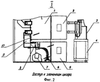
фиг.2 - доступ к элементам шкафа;figure 2 - access to the elements of the cabinet;
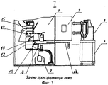
фиг.3 - замену трансформатора тока;figure 3 - replacement of the current transformer;
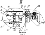
фиг.4 - заземлитель.figure 4 - grounding.
Шкаф КРУ (Фиг.1) состоит из следующих основных частей: А - релейный отсек, Б - отсек выдвижного элемента, В - отсек сборных шин, Г - кабельный отсек.The switchgear cabinet (Fig. 1) consists of the following main parts: A - relay compartment, B - drawer compartment, C - busbar compartment, G - cable compartment.
Позиция I - соответствует размещению в КРУ трансформаторов тока, а позиция II - установка в шкафу КРУ заземлителя (быстродействующего с пружинным приводом).Position I - corresponds to the placement of current transformers in the switchgear, and position II - installation of an earthing switch (quick-acting with a spring drive) in the switchgear cabinet.
Доступ к элементам шкафа, в частности к трансформаторам тока, установленным в каркасе 1 (фиг.2, позиция I), осуществляется выкатом выдвижного элемента с выключателем 3, установленным на инвентарной тележке 4, предварительно открыв дверь 2 (отсека выдвижного элемента) и дверь 5 кабельного отсека. При этом освобождается доступ (указано стрелками) к кабельной разделке 6, трансформатору 7 напряжения, заземлителю 8, трансформатору 9 тока и крышке 10, которая свободно демонтируется, освобождая свободный доступ к контактам вторичных цепей трансформаторов 9 тока. Трансформатор 9 тока, трансформатор 7 напряжения, заземлитель 8, линейные шины и силовые кабели размещены в кабельном отсеке с возможностью их разделки.Access to the cabinet elements, in particular to the current transformers installed in the frame 1 (Fig. 2, position I), is carried out by rolling out the sliding element with the
Замена трансформатора 9 тока, установленного в каркасе 1 (фиг.3, позиция I), осуществляется при открытых дверях 2, при этом выключатель 3 на инвентарной тележке 4 расположен в коридоре обслуживания, а легкосъемная перегородка 11, расположенная между отсеком выдвижного элемента и кабельным отсеком, демонтируется. Трансформатор 7 напряжения и заземлитель 8 обслуживаются ремонтными службами стационарно. Для обслуживания контактов вторичных цепей трансформаторов 9 тока (фиг.3) или его замены достаточно демонтировать шинный крепеж 12 на ошиновке ремонтируемой фазы и крепеж 15 на несущей конструкции каркаса рамы 1. Повернув блок трансформатора 9 тока (фиг.3) с шиной 13 и проходной втулкой 14 вокруг оси в сторону отсека выкатного элемента на 90 градусов в ремонтное положение, трансформатор 9 тока доступен к обслуживанию (ремонту, замене и проч.).Replacement of the
Заземлитель 8 (фиг.1, позиция II) в зависимости от схем может находиться (в данной схеме) под отсеком выкатного элемента в кабельном отсеке и приводится в действие съемной ручкой заземлителя 8. Заземлитель 8, как неотъемлемая часть любого КРУ, в целом предназначен для гарантирования безопасной работы обслуживающего персонала при проведении плановых и регламентных работ, возникающих в процессе эксплуатации шкафов КРУ.The earthing switch 8 (Fig. 1, position II), depending on the schemes, can be located (in this diagram) under the withdrawable element compartment in the cable compartment and is driven by the removable handle of the earthing
При включенном заземлителе 8 невозможно вкатить выдвижной элемент с выключателем 3 из контрольного положения в промежуточное и далее - в рабочее положение. При этом разблокированную дверь 2 отсека выдвижного элемента можно легко открыть.When the earthing
При отключенном положении заземлителя 8 специальным механизмом блокируется дверь 5 кабельного отсека.When the earthing
Основные узлы и детали заземлителя 8 (фиг.4, позиция II) состоят из: блока ножей заземления 16, в состав которого входят вал 17 с пружинами включения-отключения (на фиг. не показаны), фиксатор 18, заземляющих пластин 19, изоляторов 20 со встроенными выводами для индикатора наличия напряжения (на фиг. не показаны), шины 21 соединены с ошиновкой главной токоведущей цепи шкафа, контакты 22, дополнительно устанавливаемый навесной замок 23 дополнительной механической блокировки, одеваемый в отдельные отверстия швеллера 24 и сектора 25. На торец вала 26 привода заземлителя 8 устанавливается съемная ручка для управления заземлителем 8. Выключатель 27 путевой взаимодействует с блокировочным сектором 28, электромагнит 29, взаимодействуя с сектором 30, блокирует упомянутый вал привода заземлителя 8.The main components and parts of the ground electrode 8 (Fig. 4, position II) consist of: a block of grounding
Предложенные технические и конструктивные решения позволили улучшить массогабаритные и технико-эксплуатационные показатели и создать новую серию шкафов КРУ под торговой маркой завода-изготовителя, а именно: КУ-10С с номинальными токами до 3150 А и номинальными токами отключения 40 кА в общепромышленном исполнении и КУ-6С - с теми же параметрами, но в сейсмостойком исполнении для тепловых и атомных электростанций.The proposed technical and constructive solutions made it possible to improve the overall dimensions and technical and operational indicators and create a new series of switchgear cabinets under the brand name of the manufacturer, namely: KU-10S with rated currents of up to 3150 A and rated breaking currents of 40 kA in general industrial design and KU- 6C - with the same parameters, but in earthquake-resistant design for thermal and nuclear power plants.
Изготовленные на ОАО «РЗВА» опытные образцы шкафов КРУ после проведения всех электромеханических испытаний (НИЦ ВВА, г.Москва) полностью подтвердили их надежную работоспособность и могут быть рекомендованы для эксплуатации в народном хозяйстве на объектах электроэнергетики.The prototypes of switchgear cabinets manufactured at RZVA after all the electromechanical tests (SIC VVA, Moscow) fully confirmed their reliable performance and can be recommended for operation in the national economy at electric power facilities.
Claims (2)
Priority Applications (1)
| Application Number | Priority Date | Filing Date | Title |
|---|---|---|---|
| RU2005109354/09A RU2287882C1 (en) | 2005-05-13 | 2005-05-13 | Switchgear and control gear |
Applications Claiming Priority (1)
| Application Number | Priority Date | Filing Date | Title |
|---|---|---|---|
| RU2005109354/09A RU2287882C1 (en) | 2005-05-13 | 2005-05-13 | Switchgear and control gear |
Publications (2)
| Publication Number | Publication Date |
|---|---|
| RU2005109354A RU2005109354A (en) | 2006-11-20 |
| RU2287882C1 true RU2287882C1 (en) | 2006-11-20 |
Family
ID=37501522
Family Applications (1)
| Application Number | Title | Priority Date | Filing Date |
|---|---|---|---|
| RU2005109354/09A RU2287882C1 (en) | 2005-05-13 | 2005-05-13 | Switchgear and control gear |
Country Status (1)
| Country | Link |
|---|---|
| RU (1) | RU2287882C1 (en) |
Cited By (5)
| Publication number | Priority date | Publication date | Assignee | Title |
|---|---|---|---|---|
| RU2406200C1 (en) * | 2009-06-02 | 2010-12-10 | Открытое акционерное общество "Московское Электрооборудование и Лифты" (ОАО "МЭЛ") | Single-side service combined chamber |
| RU2406198C1 (en) * | 2009-04-14 | 2010-12-10 | Открытое акционерное общество "МЭЛ" | Complete distribution unit cabinet with house transformer |
| RU203973U1 (en) * | 2020-11-23 | 2021-04-29 | Закрытое акционерное общество "Завод электротехнического оборудования" (ЗАО "ЗЭТО") | COMPLETE SWITCHING DEVICE |
| CN114664517A (en) * | 2022-04-11 | 2022-06-24 | 无锡市锡容电力电器有限公司 | Current transformer |
| RU2864893C2 (en) * | 2024-11-08 | 2026-06-30 | Общество с ограниченной ответственностью "АЙДИ-ИНЖИНИРИНГ" | Device for distributing electrical energy with cable line test unit |
Citations (2)
| Publication number | Priority date | Publication date | Assignee | Title |
|---|---|---|---|---|
| RU2172545C1 (en) * | 2000-02-01 | 2001-08-20 | Открытое акционерное общество "Электрощит" | Metalclad switchgear cubicle |
| EP1227558A1 (en) * | 2001-01-24 | 2002-07-31 | Mitsubishi Denki Kabushiki Kaisha | Switchgear |
-
2005
- 2005-05-13 RU RU2005109354/09A patent/RU2287882C1/en not_active IP Right Cessation
Patent Citations (2)
| Publication number | Priority date | Publication date | Assignee | Title |
|---|---|---|---|---|
| RU2172545C1 (en) * | 2000-02-01 | 2001-08-20 | Открытое акционерное общество "Электрощит" | Metalclad switchgear cubicle |
| EP1227558A1 (en) * | 2001-01-24 | 2002-07-31 | Mitsubishi Denki Kabushiki Kaisha | Switchgear |
Cited By (6)
| Publication number | Priority date | Publication date | Assignee | Title |
|---|---|---|---|---|
| RU2406198C1 (en) * | 2009-04-14 | 2010-12-10 | Открытое акционерное общество "МЭЛ" | Complete distribution unit cabinet with house transformer |
| RU2406200C1 (en) * | 2009-06-02 | 2010-12-10 | Открытое акционерное общество "Московское Электрооборудование и Лифты" (ОАО "МЭЛ") | Single-side service combined chamber |
| RU203973U1 (en) * | 2020-11-23 | 2021-04-29 | Закрытое акционерное общество "Завод электротехнического оборудования" (ЗАО "ЗЭТО") | COMPLETE SWITCHING DEVICE |
| CN114664517A (en) * | 2022-04-11 | 2022-06-24 | 无锡市锡容电力电器有限公司 | Current transformer |
| CN114664517B (en) * | 2022-04-11 | 2024-03-26 | 无锡市锡容电力电器有限公司 | Current transformer |
| RU2864893C2 (en) * | 2024-11-08 | 2026-06-30 | Общество с ограниченной ответственностью "АЙДИ-ИНЖИНИРИНГ" | Device for distributing electrical energy with cable line test unit |
Also Published As
| Publication number | Publication date |
|---|---|
| RU2005109354A (en) | 2006-11-20 |
Similar Documents
| Publication | Publication Date | Title |
|---|---|---|
| KR101058918B1 (en) | Vacuum insulated switchgear | |
| JP4268991B2 (en) | Vacuum insulated switchgear | |
| CN101588026A (en) | A 24kV mid-mounted switchgear | |
| WO2010133464A1 (en) | Electrical power switch and control panel comprising power switch | |
| RU179417U1 (en) | OUTLET ELEMENT IN A COMPLETE DISTRIBUTION CABINET CABINET | |
| RU82946U1 (en) | CAMERA COMBINED ONE-SIDED SERVICE (KSO-207 "NOVATION") | |
| RU2285319C1 (en) | Switchgear and control gear cabinet and draw-out part of switchgear and control gear cabinet | |
| RU102857U1 (en) | CAMERA COMBINED ONE-SIDED SERVICE | |
| RU2550810C2 (en) | High-voltage switchgear and control gear | |
| RU82947U1 (en) | ONE-SIDED SERVICE CAMERA | |
| RU95432U1 (en) | CELL OF COMPLETE DISTRIBUTION DEVICES | |
| RU121660U1 (en) | COMPLETE DISTRIBUTION DEVICE | |
| KR100356512B1 (en) | Gas insulated switch-gear | |
| RU55513U1 (en) | CABINET OF COMPLETE DISTRIBUTION DEVICE | |
| RU113614U1 (en) | COMPLETE DISTRIBUTION DEVICE | |
| RU76511U1 (en) | CELL OF COMPLETE DISTRIBUTION DEVICES KRU / TEK-206 | |
| CN201742015U (en) | Railroad phase segment vacuum switch cabinet | |
| CN219918046U (en) | Switch cabinet | |
| CN214478653U (en) | Interlocking structure for preventing misoperation of switch cabinet sealing plate | |
| RU2210149C2 (en) | Metalclad switchgear | |
| RU26692U1 (en) | CABINET OF COMPLETE DISTRIBUTION DEVICES TYPE КРУ | |
| RU101874U1 (en) | CAMERA COMBINED ONE-SIDED SERVICE TYPE KSO-393-VM | |
| RU2005109354A (en) | COMPLETE DISTRIBUTION DEVICE | |
| RU58806U1 (en) | CAMERA COMBINED ONE-SIDED SERVICE TYPE KSO 393A-VM (OPTIONS) | |
| RU34811U1 (en) | Complete switchgear K-121 series |
Legal Events
| Date | Code | Title | Description |
|---|---|---|---|
| PC4A | Invention patent assignment |
Effective date: 20070403 |
|
| PC41 | Official registration of the transfer of exclusive right |
Effective date: 20131114 |
|
| MM4A | The patent is invalid due to non-payment of fees |
Effective date: 20150514 |