RU2250546C2 - Method for producing flexible cable conduit inserts, method for producing cable conduit flexible sleeve; flexible textile cable conduit - Google Patents
Method for producing flexible cable conduit inserts, method for producing cable conduit flexible sleeve; flexible textile cable conduit Download PDFInfo
- Publication number
- RU2250546C2 RU2250546C2 RU2003104379/09A RU2003104379A RU2250546C2 RU 2250546 C2 RU2250546 C2 RU 2250546C2 RU 2003104379/09 A RU2003104379/09 A RU 2003104379/09A RU 2003104379 A RU2003104379 A RU 2003104379A RU 2250546 C2 RU2250546 C2 RU 2250546C2
- Authority
- RU
- Russia
- Prior art keywords
- sleeve
- cable
- textile
- conduit
- pulling
- Prior art date
Links
Images
Classifications
-
- H—ELECTRICITY
- H02—GENERATION; CONVERSION OR DISTRIBUTION OF ELECTRIC POWER
- H02G—INSTALLATION OF ELECTRIC CABLES OR LINES, OR OF COMBINED OPTICAL AND ELECTRIC CABLES OR LINES
- H02G3/00—Installations of electric cables or lines or protective tubing therefor in or on buildings, equivalent structures or vehicles
- H02G3/02—Details
- H02G3/04—Protective tubing or conduits, e.g. cable ladders or cable troughs
-
- H—ELECTRICITY
- H02—GENERATION; CONVERSION OR DISTRIBUTION OF ELECTRIC POWER
- H02G—INSTALLATION OF ELECTRIC CABLES OR LINES, OR OF COMBINED OPTICAL AND ELECTRIC CABLES OR LINES
- H02G9/00—Installations of electric cables or lines in or on the ground or water
- H02G9/06—Installations of electric cables or lines in or on the ground or water in underground tubes or conduits; Tubes or conduits therefor
-
- G—PHYSICS
- G02—OPTICS
- G02B—OPTICAL ELEMENTS, SYSTEMS OR APPARATUS
- G02B6/00—Light guides; Structural details of arrangements comprising light guides and other optical elements, e.g. couplings
- G02B6/44—Mechanical structures for providing tensile strength and external protection for fibres, e.g. optical transmission cables
- G02B6/4439—Auxiliary devices
- G02B6/4459—Ducts; Conduits; Hollow tubes for air blown fibres
-
- H—ELECTRICITY
- H02—GENERATION; CONVERSION OR DISTRIBUTION OF ELECTRIC POWER
- H02G—INSTALLATION OF ELECTRIC CABLES OR LINES, OR OF COMBINED OPTICAL AND ELECTRIC CABLES OR LINES
- H02G9/00—Installations of electric cables or lines in or on the ground or water
- H02G9/06—Installations of electric cables or lines in or on the ground or water in underground tubes or conduits; Tubes or conduits therefor
- H02G9/065—Longitudinally split tubes or conduits therefor
-
- Y—GENERAL TAGGING OF NEW TECHNOLOGICAL DEVELOPMENTS; GENERAL TAGGING OF CROSS-SECTIONAL TECHNOLOGIES SPANNING OVER SEVERAL SECTIONS OF THE IPC; TECHNICAL SUBJECTS COVERED BY FORMER USPC CROSS-REFERENCE ART COLLECTIONS [XRACs] AND DIGESTS
- Y10—TECHNICAL SUBJECTS COVERED BY FORMER USPC
- Y10T—TECHNICAL SUBJECTS COVERED BY FORMER US CLASSIFICATION
- Y10T83/00—Cutting
- Y10T83/04—Processes
- Y10T83/0476—Including stacking of plural workpieces
-
- Y—GENERAL TAGGING OF NEW TECHNOLOGICAL DEVELOPMENTS; GENERAL TAGGING OF CROSS-SECTIONAL TECHNOLOGIES SPANNING OVER SEVERAL SECTIONS OF THE IPC; TECHNICAL SUBJECTS COVERED BY FORMER USPC CROSS-REFERENCE ART COLLECTIONS [XRACs] AND DIGESTS
- Y10—TECHNICAL SUBJECTS COVERED BY FORMER USPC
- Y10T—TECHNICAL SUBJECTS COVERED BY FORMER US CLASSIFICATION
- Y10T83/00—Cutting
- Y10T83/04—Processes
- Y10T83/0524—Plural cutting steps
- Y10T83/0538—Repetitive transverse severing from leading edge of work
- Y10T83/0548—With longitudinal severing
Abstract
Description
1. Область изобретения1. Field of invention
Настоящее изобретение, в общем, относится к такому типу трубчатого кабелепровода, который можно использовать для прокладки подземных кабелей, таких как волоконно-оптический кабель, коаксиальный кабель или подобные. Более конкретно настоящее изобретение относится к устройству разделения перегородками, которое можно ввести в такой кабелепровод для разделения кабелепровода на отдельные камеры или ячейки, и к способу изготовления такого устройства.The present invention, in General, relates to this type of tubular conduit, which can be used for laying underground cables, such as fiber optic cable, coaxial cable or the like. More specifically, the present invention relates to a partitioning device that can be inserted into such a conduit for dividing the conduit into separate chambers or cells, and to a method for manufacturing such a device.
Кабель, такой как коммуникационный волоконно-оптический кабель, часто прокладывается под землей на большие расстояния. Из уровня техники известна такая прокладка кабеля в почве, которая не приводит к загромождению территории над землей самим кабелем и его соответствующими опорными сооружениями. Кроме того, при размещении кабеля под землей он становится более защищенным от погодных условий и других возможных источников повреждений.A cable, such as a fiber optic communications cable, is often routed underground for long distances. The prior art knows such a cable laying in the soil, which does not lead to clutter of the territory above the ground by the cable itself and its corresponding supporting structures. In addition, when placing the cable underground it becomes more protected from weather conditions and other possible sources of damage.
Кроме того, для обеспечения наиболее полной защиты кабеля в земле из уровня техники известно размещение кабеля внутри кабелепровода. Кабелепровод часто формируют из участков поливинилхлоридных труб или тому подобных, которые прокладывают в земле. Затем через кабелепровод вдувают веревку, прикрепленную, в свою очередь, к одному концу кабеля. При вытягивании веревки кабель протягивают через кабелепровод. После размещения кабеля внутри кабелепровода он будет защищен от повреждений, которые могут быть вызваны погодными условиями, водой и т.п.In addition, to provide the most complete cable protection in the ground, it is known in the art to place the cable inside the conduit. A conduit is often formed from sections of polyvinyl chloride pipes or the like that are laid in the ground. Then, through the conduit, a rope is blown, attached, in turn, to one end of the cable. When pulling the rope, the cable is pulled through the conduit. After placing the cable inside the conduit, it will be protected from damage that may be caused by weather conditions, water, etc.
Было обнаружено, что некоторые грызуны иногда прогрызают подземный кабелепровод. Поэтому чаще всего используются достаточно большие подземные кабелепроводы, имеющие диаметр два или более дюймов, и препятствуют нанесению повреждений от большинства грызунов. Хотя такой кабелепровод обеспечивает надежную защиту кабеля, внутри такого кабелепровода имеется много неиспользованного или "мертвого" пространства. С появлением волоконно-оптических кабелей, которые могут иметь диаметр только полдюйма или менее, большая часть площади в поперечном сечении обычного кабелепровода не используется и поэтому остается мертвое пространство.It has been discovered that some rodents sometimes gnaw through an underground conduit. Therefore, rather large underground conduits, having a diameter of two or more inches, are most often used and prevent damage from most rodents. Although such a conduit provides reliable cable protection, there is a lot of unused or dead space inside such a conduit. With the advent of fiber optic cables, which can only have a diameter of half an inch or less, most of the cross-sectional area of a conventional conduit is not used and therefore dead space remains.
После размещения кабелепровода может потребоваться введение второго кабеля через этот кабелепровод. С точки зрения стоимости и времени представляет интерес использование мертвого пространства внутри существующего кабелепровода, а не прокладка нового участка кабелепровода. Однако было обнаружено, что трудно просто ввести второй кабель в кабелепровод, который уже содержит первый кабель. При вдувании веревки в кабелепровод, который уже содержит кабель, или при протягивании второго кабеля через кабелепровод первый кабель часто является непреодолимым препятствием, делая невозможным прокладку второго кабеля.After placing the conduit, it may be necessary to insert a second cable through this conduit. From the point of view of cost and time, it is of interest to use the dead space inside an existing conduit, rather than laying a new section of the conduit. However, it was found that it is difficult to simply insert the second cable into the conduit, which already contains the first cable. When the rope is blown into the conduit that already contains the cable, or when the second cable is pulled through the conduit, the first cable is often an insurmountable obstacle, making it impossible to lay the second cable.
Существует изделие, которое устраняет некоторые из вышеупомянутых недостатков. Структура внутреннего кабельного канала с одним рукавом включает в себя пару прилегающих слоев в форме полос, выполненных из гибкого текстильного материала, которые соединены вдоль своих продольных кромок, образуя при этом канал, через который кабель может простираться в продольном направлении через структуру внутреннего кабельного канала, сформированную между слоями. Расположенные рядом слои имеют различную ширину между своими продольными кромками, за счет чего широкий слой выпячивается относительно узкого слоя, придавая каналу открытую конфигурацию. Поэтому существует потребность в недорогом и эффективном способе изготовления такого устройства для гибкого разделения перегородками кабелепровода. Кроме того, при некоторых применениях желательно обеспечить устройство для разделения перегородками кабелепровода с многочисленными рукавами, где каждый рукав включает в себя множество ячеек для приема кабелей и тому подобного.There is a product that eliminates some of the aforementioned disadvantages. The structure of the internal cable channel with one sleeve includes a pair of adjacent layers in the form of strips made of flexible textile material, which are connected along their longitudinal edges, forming a channel through which the cable can extend in the longitudinal direction through the structure of the internal cable channel formed between layers. The adjacent layers have different widths between their longitudinal edges, due to which the wide layer protrudes from a relatively narrow layer, giving the channel an open configuration. Therefore, there is a need for an inexpensive and efficient method for manufacturing such a device for flexible separation by conduit baffles. In addition, in some applications, it is desirable to provide a device for separating the conduit walls with multiple sleeves, where each sleeve includes a plurality of cells for receiving cables and the like.
2. Описание предшествующего уровня техники2. Description of the Related Art
Все цитируемые патенты, указанные в описании, представлены в качестве аналогов.All cited patents referred to in the description are presented as analogues.
В патенте США №5587115, выданном Аллену (Allen), описан способ изготовления кабелепроводной сборки с плавающей перегородкой путем выдавливания оболочки через головку экструдера при одновременной подаче элемента перегородки в оболочку в процессе ее выдавливания для образования множества камер. Если кабелепроводная сборка изготавливается со шнуром, таким как веревка или кабель, веревку и/или кабель аналогично подают в оболочку, расположенную рядом с элементом перегородки, в одну или обе камеры.US Pat. No. 5,587,115 to Allen describes a method for manufacturing a conduit assembly with a floating baffle by extruding a sheath through an extruder head while simultaneously feeding a baffle member into the sheath during extrusion to form multiple chambers. If the conduit assembly is made with a cord, such as a rope or cable, the rope and / or cable is likewise fed into the sheath located next to the partition element into one or both chambers.
В патенте США №4836968, выданном Какмакси (Cakmakci), описан способ изготовления вставки волоконно-оптического кабелепровода путем непрерывного выдавливания пластмассового материала во вставку кабелепровода с многочисленными камерами, включающую в себя, по меньшей мере, две по существу параллельные первую и вторую камеры, разнесенные на расстояние в продольном направлении. Конфигурация в поперечном сечении каждой из камер определяется, в общем, с помощью параллельных внутренней и внешней боковых стенок, соединенных на одной их кромке с помощью базовой стенки и соединенных на их противоположной кромке с помощью верхней стенки. Шарнирная часть соединяет вместе расположенные рядом края внутренних стенок и базовых стенок камер. Противоположные концы внутренних стенок расположены дальше, чем расположенные рядом концы внутренних стенок, для того, чтобы оставить внешние поверхности внутренних стенок для охлаждающей среды в процессе изготовления.US Pat. No. 4,836,968 to Cakmakci describes a method for manufacturing a fiber optic conduit insert by continuously extruding plastic material into a multiple conduit insert including at least two substantially parallel first and second chambers spaced apart a distance in the longitudinal direction. The cross-sectional configuration of each of the chambers is determined, in general, by means of parallel inner and outer side walls connected at one edge with a base wall and connected at their opposite edge with an upper wall. The hinge part connects together adjacent edges of the inner walls and the base walls of the chambers. The opposite ends of the inner walls are located further than the adjacent ends of the inner walls in order to leave the outer surfaces of the inner walls for the cooling medium during the manufacturing process.
В патенте США №4582093, выданном Хаббарду (Hubbard), описан способ изготовления вставки волоконно-оптического кабелепровода путем использования процесса экструзии пластмассы для производства вставки кабелепровода с многочисленными камерами, которые можно использовать для преобразования однокамерного кабелепровода в многокамерный кабелепровод. В частности, вставка кабелепровода включает в себя множество взаимодействующих, протяженных в продольном направлении стенок, имеющих части с изогнутой внешней поверхностью и образующих множество параллельных, разнесенных в пространстве камер одинаковой длины. В предпочтительном варианте осуществления изобретения две идентичных вставки кабелепровода расположены во взаимном отношении друг к другу и образуют сборку для вставки в однокамерный кабелепровод.US Pat. No. 4,508,093 to Hubbard describes a method for manufacturing an optical fiber conduit insert by using a plastic extrusion process to produce a multiple conduit insert that can be used to convert a single-chamber conduit to a multi-chamber conduit. In particular, the conduit insert includes a plurality of interacting longitudinally extending walls having parts with a curved outer surface and forming a plurality of parallel, spaced apart chambers of the same length. In a preferred embodiment of the invention, two identical conduit inserts are arranged mutually relative to each other and form an assembly for insertion into a single-chamber conduit.
Ниже представлены другие патенты из известного уровня техники, раскрывающие устройства, которые облегчают размещение многочисленных кабелей внутри одного кабелепровода:The following are other patents from the prior art, disclosing devices that facilitate the placement of multiple cables within a single conduit:
Один недостаток, присущий многим из этих устройств, заключается в том, что они, главным образом, представляют собой прессованные пластмассовые изделия, которые не очень хорошо сгибаются или скручиваются. Трудно ввести полужесткую, пластмассовую структуру в жесткий канал или трубу, особенно в тот, который уже содержит кабель. Кроме того, скорость установки жесткой перегородки строго ограничена сопротивлением за счет трения и выделяемым при этом теплом. Гибкий кабелепровод с тканевыми рукавами и многочисленными ячейками позволяет устранить упомянутые выше недостатки, и, таким образом, имеется потребность в эффективном и недорогом способе изготовления изделия. Кроме того, желательно получить многорукавный кабелепровод, содержащий множество ячеек в рукаве, для приема большого жгута кабелей, а также способ изготовления такого устройства.One drawback inherent in many of these devices is that they mainly are molded plastic products that do not bend or twist very well. It is difficult to insert a semi-rigid, plastic structure into a rigid duct or pipe, especially one that already contains the cable. In addition, the installation speed of the rigid partition is strictly limited by the resistance due to friction and the heat generated during this. A flexible conduit with fabric sleeves and numerous cells eliminates the aforementioned disadvantages, and thus there is a need for an efficient and inexpensive method of manufacturing an article. In addition, it is desirable to obtain a multi-sleeve conduit containing many cells in the sleeve for receiving a large cable bundle, as well as a method of manufacturing such a device.
Сущность изобретенияSUMMARY OF THE INVENTION
Таким образом, основной задачей настоящего изобретения является обеспечение эффективного и недорогого способа изготовления гибких кабелепроводных вкладышей для волоконно-оптических кабелей, коаксиальных кабелей, содержащего следующие этапы:Thus, the main objective of the present invention is to provide an effective and inexpensive method of manufacturing flexible conduit inserts for fiber optic cables, coaxial cables, comprising the following steps:
осуществляют пропускание, по меньшей мере, двух слоев текстильного материала через устройство для сшивания в продольном направлении,passing at least two layers of textile material through a device for stitching in the longitudinal direction,
сшивают множество швов вдоль материала в продольном направлении для формирования множества продольных рукавов иstitching a plurality of seams along the material in the longitudinal direction to form a plurality of longitudinal sleeves and
разрезают указанный текстильный материал в продольном направлении для отделения заданного числа рукавов от остальной части материала.cut the specified textile material in the longitudinal direction to separate a given number of sleeves from the rest of the material.
Кроме того, согласно указанному способу используют, по меньшей мере, три слоя текстильного материала, обеспечивая множество рукавов, каждый из которых имеет, по меньшей мере, две отдельные внутренние ячейки для приема волоконно-оптического кабеля.In addition, according to the method, at least three layers of textile material are used, providing a plurality of sleeves, each of which has at least two separate inner cells for receiving an optical fiber cable.
Указанный способ дополнительно включает в себя этап свертывания каждого отдельного рукава в рулон для хранения и транспортировки. Согласно указанному способу материал выбирают из группы, содержащей: текстильную ткань, вязаное полотно, нетканый материал, склеенный смолой грубый холст, полимерную пленку, уточное трикотажное переплетение или любую комбинацию указанных видов текстильных материалов.The specified method further includes the step of rolling each individual sleeve into a roll for storage and transportation. According to the specified method, the material is selected from the group consisting of: textile fabric, knitted fabric, nonwoven material, coarse canvas glued with resin, polymer film, weft knit weaving, or any combination of these types of textile materials.
Кроме того, указанный способ дополнительно включает в себя этап загибания, по меньшей мере, верхнего или нижнего слоя материала перед сшиванием для обеспечения рукава, имеющего протяженную, но складную конфигурацию ячейки. А также дополнительно включает в себя этап обеспечения множества шнуров или лент для протягивания кабеля таким образом, чтобы внутри каждой ячейки каждого рукава размещался один шнур для протягивания кабеля с возможностью скольжения. In addition, this method further includes the step of folding at least the upper or lower layer of material before stitching to provide a sleeve having an extended but folding cell configuration. It also further includes the step of providing a plurality of cords or tapes for pulling the cable so that inside each cell of each sleeve there is one cord for sliding the cable.
Согласно указанному способу используют, по меньшей мере, четыре слоя текстильного материала, обеспечивающих множество рукавов, каждый из которых имеет, по меньшей мере, три отдельные внутренние ячейки для приема волоконно-оптического кабеля.According to the method, at least four layers of textile material are used that provide a plurality of sleeves, each of which has at least three separate inner cells for receiving an optical fiber cable.
Кроме того, указанный способ может дополнительно включть в себя этап нанесения клея между швами для получения законченной кромки с обеих сторон каждого рукава после разрезания в продольном направлении. А также дополнительно включать в себя этап термического соединения материала между швами для получения законченной кромки с обеих сторон каждого рукава после разрезания в продольном направлении. Кроме того, согласно указанному способу дополнительно включают в себя этап использования горячего ножа для разрезания материала в продольном направлении.In addition, this method may further include the step of applying glue between the seams to obtain a finished edge on both sides of each sleeve after cutting in the longitudinal direction. And also additionally include the step of thermal connection of the material between the seams to obtain a finished edge on both sides of each sleeve after cutting in the longitudinal direction. In addition, according to the specified method further include the step of using a hot knife to cut the material in the longitudinal direction.
При этом согласно указанному способу каждую ячейку внутри рукава маркируют с тем, чтобы ее можно было отличить от других ячеек внутри рукава. При этом согласно указанному способу, по меньшей мере, одну из лент для протягивания кабеля в каждом рукаве маркируют в виде мерных приращений. А также на каждой из лент для протягивания кабеля в рукаве осуществляют печать или окраску с тем, чтобы ее можно было отличить от других лент для протягивания кабеля внутри рукава.Moreover, according to the specified method, each cell inside the sleeve is marked so that it can be distinguished from other cells inside the sleeve. Moreover, according to the specified method, at least one of the tapes for pulling the cable in each sleeve is marked in the form of measured increments. Also, on each of the tapes for pulling the cable in the sleeve, printing or coloring is carried out so that it can be distinguished from other tapes for pulling the cable inside the sleeve.
Согласно другому важному аспекту настоящего изобретения обеспечивается способ изготовления гибких рукавов кабелепровода для волоконно-оптических кабелей, коаксиальных кабелей, содержащий следующие этапы:According to another important aspect of the present invention, there is provided a method for manufacturing flexible conduit sleeves for fiber optic cables, coaxial cables, comprising the steps of:
обеспечивают, по меньшей мере, два сложенных слоя текстильного материала,provide at least two folded layers of textile material,
прикрепляют сложенные слои вместе путем создания множества параллельных, продольных швов, таким образом создавая множество параллельных, продольных рукавов и осуществляют отделение заданного числа рукавов от указанного материала в виде отдельного рукава или наборов множества рукавов.attach the folded layers together by creating a plurality of parallel, longitudinal seams, thus creating a plurality of parallel, longitudinal sleeves, and separate a predetermined number of sleeves from said material in the form of a single sleeve or sets of multiple sleeves.
Кроме того, указанный способ дополнительно включает в себя этап скатывания отдельного рукава или набора рукавов в рулон для транспортировки, хранения или использования. При этом продольные швы могут быть сформированы путем термического соединения, путем нанесения клея.In addition, this method further includes the step of rolling a single sleeve or a set of sleeves into a roll for transportation, storage or use. In this case, longitudinal seams can be formed by thermal bonding, by applying glue.
Кроме того, согласно указанному способу используют, по меньшей мере, три слоя текстильного материала, обеспечивая множество рукавов, каждый из которых имеет, по меньшей мере, две отдельные внутренние ячейки для приема волоконно-оптического кабеля. При этом текстильный материал может быть выбран из группы, содержащей: текстильную ткань, вязаное полотно, нетканый материал, склеенный смолой грубый холст, полимерную пленку, уточное трикотажное переплетение или любую комбинацию из указанной группы.In addition, according to the method, at least three layers of textile material are used, providing a plurality of sleeves, each of which has at least two separate inner cells for receiving an optical fiber cable. In this case, the textile material can be selected from the group consisting of: textile fabric, knitted fabric, non-woven material, coarse canvas glued with resin, polymer film, weft knit weaving, or any combination of the specified group.
Указанный способ дополнительно включает в себя этап загибания, по меньшей мере, верхнего или нижнего слоя материала перед формированием швов для обеспечения рукава, имеющего протяженную, но складную конфигурацию ячейки.The specified method further includes the step of folding at least the upper or lower layer of material before forming the seams to provide a sleeve having an extended but folding cell configuration.
А также дополнительно включает в себя этап обеспечения множества шнуров или лент для протягивания кабеля таким способом, чтобы один шнур для протягивания кабеля размещался с возможностью скольжения внутри каждой ячейки каждого рукава.And also further includes the step of providing multiple cords or tapes for pulling the cable in such a way that one cord for pulling the cable is placed with the possibility of sliding inside each cell of each sleeve.
Кроме того, согласно указанному способу используют, по меньшей мере, четыре слоя текстильного материала, обеспечивая множество рукавов, каждый из которых имеет, по меньшей мере, три отдельные внутренние ячейки для приема волоконно-оптического кабеля. При этом каждую ячейку внутри рукава маркируют с тем, чтобы ее можно было отличить от других ячеек внутри рукава.In addition, according to the method, at least four layers of textile material are used, providing a plurality of sleeves, each of which has at least three separate inner cells for receiving an optical fiber cable. Moreover, each cell inside the sleeve is marked so that it can be distinguished from other cells inside the sleeve.
Согласно указанному способу, по меньшей мере, одну из лент для протягивания кабеля в каждом рукаве маркируют в виде мерных приращений. А на каждой из лент для протягивания кабеля в рукаве осуществляют печать или окраску с тем, чтобы ее можно было отличить от других лент для протягивания кабеля внутри рукава.According to this method, at least one of the tapes for pulling the cable in each sleeve is marked in the form of measured increments. And on each of the tapes for pulling the cable in the sleeve, printing or coloring is carried out so that it can be distinguished from other tapes for pulling the cable inside the sleeve.
Согласно еще одному аспекту изобретения заявлен гибкий текстильный кабелепровод для волоконно-оптических кабелей, коаксиальных кабелей, при этом кабелепровод содержит, по меньшей мере, два элемента рукава, которые соединены и расположены параллельно, и при этом каждый элемент рукава имеет, по меньшей мере, одну ячейку для приема кабеля.According to another aspect of the invention, a flexible textile conduit for fiber optic cables, coaxial cables is claimed, wherein the conduit comprises at least two sleeve elements that are connected and arranged in parallel, and each sleeve element has at least one cell for cable reception.
Кроме того, согласно указанному аспекту в текстильном кабелепроводе каждый элемент рукава содержит, по меньшей мере, две ячейки для приема одного кабеля в одну ячейку. А между каждым из элементов рукава выполнена перфорация для легкого отделения элементов рукава друг от друга.In addition, according to this aspect, in a textile conduit, each sleeve element comprises at least two cells for receiving one cable in one cell. And between each of the sleeve elements perforation is made for easy separation of the sleeve elements from each other.
Согласно указанному текстильному кабелепроводу лента для протягивания кабеля расположена в каждой ячейке с возможностью скольжения. А структура сформирована, по меньшей мере, из двух отдельных листов материала.According to the specified textile conduit, the tape for pulling the cable is slidable in each cell. And the structure is formed of at least two separate sheets of material.
Согласно указанному кабелепроводу текстильный материал может быть выбран из группы, содержащей: текстильную ткань, вязаное полотно, нетканый материал, склеенный смолой грубый холст, полимерную пленку, уточное трикотажное переплетение или любую комбинацию из группы.According to the specified conduit, the textile material can be selected from the group consisting of: textile fabric, knitted fabric, non-woven material, coarse canvas glued with resin, polymer film, weft knit weave, or any combination of the group.
При этом в указанном текстильном кабелепроводе рукава и ячейки имеют конфигурацию с открытой ячейкой, но складываются в поперечном направлении. А каждая ячейка внутри рукава маркируется с тем, чтобы ее можно было отличить от других ячеек внутри рукава.In this textile conduit, the sleeves and cells are configured with an open cell, but fold in the transverse direction. And each cell inside the sleeve is marked so that it can be distinguished from other cells inside the sleeve.
Кроме того, согласно указанному текстильному кабелепроводу, по меньшей мере, одна из лент для протягивания кабеля в каждом рукаве имеет маркировку в виде мерных приращений. Причем каждая из лент для протягивания кабеля в рукаве согласно указанному кабелепроводу имеет печатную маркировку или окраску с тем, чтобы ее можно было отличить от других лент для протягивания кабеля внутри рукава. А в указанном текстильном кабелепроводе каждый рукав включает в себя три ячейки для приема кабеля.In addition, according to the specified textile conduit, at least one of the tapes for pulling the cable in each sleeve is marked in the form of measured increments. Moreover, each of the tapes for pulling the cable in the sleeve according to the specified conduit has a printed marking or coloring so that it can be distinguished from other tapes for pulling the cable inside the sleeve. And in said textile conduit, each sleeve includes three cells for receiving a cable.
Краткое описание чертежейBrief Description of the Drawings
Эти и другие особенности, аспекты и преимущества настоящего изобретения станут понятны из следующего описания, прилагаемой формулы изобретения и сопроводительных чертежей, на которых:These and other features, aspects and advantages of the present invention will become apparent from the following description, the appended claims and the accompanying drawings, in which:
на фиг.1 представлен перспективный вид рукава гибкого кабелепровода с многочисленными ячейками;figure 1 presents a perspective view of the sleeve of a flexible conduit with numerous cells;
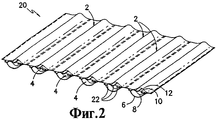
на фиг.2 представлен перспективный вид ряда рукавов гибкого кабелепровода с многочисленными ячейками, изготовленных параллельно, согласно настоящему изобретению; иfigure 2 presents a perspective view of a number of sleeves of a flexible conduit with multiple cells made in parallel, according to the present invention; and
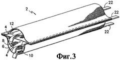
на фиг.3 представлен перспективный вид рукава гибкого кабелепровода с многочисленными ячейками, имеющего ровные и без выступов продольные кромки.figure 3 presents a perspective view of the sleeve of a flexible conduit with numerous cells, having smooth and without protrusions longitudinal edges.
Подробное описаниеDetailed description
На фиг.1 представлен гибкий кабелепровод 2 с многочисленными ячейками, предназначенный для использования в качестве одиночной структуры рукава кабелепровода внутреннего кабельного канала для волоконно-оптических кабелей, коаксиальных кабелей или тому подобного. Указанный вариант осуществления структуры раскрыт в поданной заявке на патент США №09/400778, которая включена в данном описании в качестве ссылки. Структура кабелепровода имеет множество каналов 4, которые сформированы с помощью взаимосвязанных слоев ткани 6, 8, 10, 12. В первом варианте осуществления изобретения структура имеет три канала 4, сформированных с помощью вышеупомянутых слоев, которые соединены между собой на своих противоположных продольных боковых краевых частях, имеющих краевые части нижнего слоя 6, которые накладываются на краевые части других слоев. Слои сшиваются или соединяются с помощью других подходящих способов, таких как ультразвуковая сварка или склеивание, обеспечивающих соединение слоев вместе. На фиг.1 видно, что противоположные продольные боковые краевые части нижней полосы загибают над подобными частями других полос и сшивают для формирования показанной структуры.Figure 1 shows a
На фиг.2 показан альтернативный вариант осуществления структуры 20 кабелепровода согласно настоящему изобретению. Обнаружено, что структуру кабелепровода можно изготовить более эффективно и недорого, если многочисленные полоски и шнуры 22 для протягивания кабеля укладывают в стопу и размещают таким способом, чтобы многочисленные рукава структуры кабелепровода можно было изготовить одновременно с параллельным размещением, показанным на фигуре. На фиг.2 представлен вариант осуществления, где элементы 2 рукава параллельно связаны между собой. Этот вариант осуществления позволяет разделить элементы рукава на отдельные модули или, при необходимости, на многочисленные модули. После разделения продольные кромки рукава кабелепровода разрезают так, чтобы каждый слой был выровнен с другими (фиг.3), в отличие от варианта осуществления, показанного на фиг.1, где нижний слой используется для загибания вокруг кромок других слоев.Figure 2 shows an alternative embodiment of the
Способ изготовления согласно варианту осуществления, показанному на фиг.2, включает в себя подачу нескольких сложенных листов 6, 8, 10 и 12 через кромкогибочное устройство, швейную машину и продольно-резательное устройство. В предпочтительном варианте осуществления используют четыре сложенных листа, из которых, в конечном счете, формируют три ячейки 4 или камеры в одном рукаве 2 кабелепровода. Однако следует понимать, что можно использовать любое число листов для получения необходимого числа ячеек в рукаве кабелепровода.The manufacturing method according to the embodiment shown in FIG. 2 includes feeding several folded
Кроме того, дополнительный вариант осуществления предусматривает сгибание одного листа материала для образования множества слоев для конечного продукта, в отличие от использования отдельно сложенных листов материала. Полный конечный продукт можно изготовить, при необходимости, из одного листа материала.In addition, an additional embodiment provides for folding one sheet of material to form multiple layers for the final product, as opposed to using separately folded sheets of material. The complete end product can be made, if necessary, from one sheet of material.
В предпочтительном варианте осуществления способа изготовления сложенные листы сначала пропускают через кромкогибочное устройство, которое размещает один лист в натянутом состоянии в поперечном направлении. Другие листы сгибают для создания по существу продольных складок или волн поперек поперечного направления материала. Эти складки представляют собой части материала листа, которые должны выступать относительно натянутого листа в центральной точке на складке, в конечном счете образуя продольные камеры или ячейки внутри каждого рукава кабелепровода. Кромкогибочное устройство обеспечивает ввод лент или шнуров 22 для протягивания в каждую ячейку, созданную с помощью складки, так, чтобы каждая ячейка в конечном счете включала в себя ленту для протягивания с возможностью скольжения.In a preferred embodiment of the manufacturing method, the folded sheets are first passed through an edging device that places one sheet in a transverse tension state. Other sheets are bent to create substantially longitudinal folds or waves across the transverse direction of the material. These folds are pieces of sheet material that should protrude relative to the stretched sheet at a central point on the fold, ultimately forming longitudinal chambers or cells within each sleeve of the conduit. The bending device allows the entry of tapes or
Дополнительным этапом в способе изготовления является нанесение соответствующего клея вдоль продольных линий соприкосновения между складками. Этот этап предусматривает нанесение слоя клея для соединения вместе всех слоев в продольном направлении между двух продольных линий строчки (которые еще не присутствуют в способе изготовления), где прокладки внутреннего кабельного канала будут разрезаться на отдельные части или рукава. Такое размещение обеспечивает законченную кромку с обеих сторон каждого рукава после этапа разрезания в продольном направлении для предотвращения распутывания или изнашивания материала.An additional step in the manufacturing method is the application of appropriate glue along the longitudinal lines of contact between the folds. This step involves applying a layer of glue to join together all the layers in the longitudinal direction between two longitudinal stitch lines (which are not yet present in the manufacturing method), where the gaskets of the internal cable channel will be cut into separate parts or sleeves. This arrangement provides a finished edge on both sides of each sleeve after the cutting step in the longitudinal direction to prevent unraveling or fraying of the material.
После формирования складок и введения, по меньшей мере, первых частей лент для протягивания кабеля сложенный материал подается в швейную машину, такую как Маливатта Карла Мейера ((Maliwatt by Karl Mayer). Между каждой складкой сшивают два шва в продольном направлении вдоль основания складки, предпочтительно в стороне на расстоянии около 1/2 дюйма. Швы фиксируют складки по месту в их открытой конфигурации, как показано на фиг.2. В дополнительном варианте осуществления слои материала можно скреплять с помощью других средств, которые отличаются от сшивания и включают в себя такие средства, как склеивание, термосклеивание, ультразвуковая сварка или любое другое подходящее средство, включающее в себя их комбинации.After the folds are formed and at least the first parts of the cable pulling tapes are inserted, the folded material is fed into a sewing machine such as Maliwatt by Karl Mayer. Two seams are sewn longitudinally along the crease base between each fold, preferably to the side at a distance of about 1/2 ". The seams fix the folds in place in their open configuration, as shown in figure 2. In an additional embodiment, the layers of material can be bonded using other means that are different from stitching Ia and include means such as gluing, heat sealing, ultrasonic welding or any other suitable means including a combination thereof.
После сшивания собранный материал разрезают на отдельные полосы или, при необходимости, на многочисленные параллельные полосы. Материал разрезают между двумя стежками так, чтобы каждая структура кабелепровода включала в себя один шов на каждом продольном краю. Если используется другое средство для прикрепления слоев вместе, важно, чтобы этап разрезания в продольном направлении не нарушал шов с обеих сторон структуры рукава кабелепровода. Задача этого способа изготовления заключается в получении многочисленных параллельных полос структуры кабелепровода, которые можно разделить по мере необходимости без нарушения целостности структуры рукава кабелепровода и/или ячеек. Может потребоваться разрезание материала для получения одиночных элементов рукава, или альтернативно, может потребоваться разрезание материала на двойные элементы рукава, тройные элементы рукава или подобные. Предпочтительным способом разрезания в продольном направлении является ротационное срезание, и альтернативные способы, полезные для операции разрезания в продольном направлении, включают в себя ультразвуковой способ, горячий нож, ротационный нож и тому подобное.After stitching, the collected material is cut into separate strips or, if necessary, into numerous parallel strips. The material is cut between two stitches so that each conduit structure includes one seam at each longitudinal edge. If another means is used to attach the layers together, it is important that the cutting step in the longitudinal direction does not break the seam on both sides of the conduit sleeve structure. The objective of this manufacturing method is to obtain multiple parallel bands of the conduit structure, which can be divided as necessary without violating the integrity of the structure of the conduit sleeve and / or cells. It may be necessary to cut the material to obtain single sleeve elements, or alternatively, it may be necessary to cut the material into double sleeve elements, triple sleeve elements, or the like. A preferred longitudinal cutting method is rotary cutting, and alternative methods useful for the longitudinal cutting operation include an ultrasonic method, a hot knife, a rotary knife, and the like.
С другой стороны, сборку из параллельных рукавов можно перфорировать между рукавами, которые устраняют потребность в этапе разрезания в продольном направлении. Перфорация позволяет разделить рукава в любой конфигурации, включая конфигурацию с одним рукавом, конфигурацию с двойным рукавом и так далее. Этот этап разделения можно выполнить на месте установки, при необходимости, так, чтобы решение относительно желательного числа рукавов можно было принять после завершения процесса изготовления.On the other hand, an assembly of parallel arms can be perforated between the arms, which eliminate the need for a cutting step in the longitudinal direction. Perforation allows you to split the sleeves in any configuration, including a configuration with one sleeve, a configuration with a double sleeve, and so on. This separation step can be performed at the installation site, if necessary, so that a decision on the desired number of hoses can be made after completion of the manufacturing process.
В предпочтительном варианте осуществления после этапа разрезания в продольном направлении структуру рукава кабелепровода скатывают в рулон для транспортировки и хранения. Предпочтительная структура рукавов кабелепровода позволяет сжимать рукав до плоской конфигурации в рулоне, но при раскручивании с рулона она должна принимать конфигурацию с открытыми ячейками. Для транспортировки и хранения можно использовать и другие средства для упаковки рукавов кабелепровода, включая коробки, катушки и подобное.In a preferred embodiment, after the cutting step in the longitudinal direction, the conduit sleeve structure is rolled up for transportation and storage. The preferred conduit sleeve structure allows the sleeve to be squeezed to a flat configuration in a roll, but when unwound from a roll, it should take an open-cell configuration. For transportation and storage, other means for packaging conduit sleeves, including boxes, spools and the like, can be used.
Другой вариант осуществления может предусматривать устройство кодирования или идентификации для распознавания отдельных ячеек внутри рукава кабелепровода. Важно отличить одну ячейку от другой при попытке проложить кабель через рукав кабелепровода. Человек, который прикрепляет ленту к кабелю для его протягивания на одном конце рукава, должен сообщить другому человеку, расположенному на другом конце, о том, какую ленту для прокладки кабеля необходимо протягивать через рукав кабелепровода. Эту идентификацию ячейки можно осуществить различными путями, включая цветовое кодирование ячеек или слоев, печатное или цветовое кодирование швов. Кроме того, на внешний слой рукава кабелепровода можно нанести разметку в виде мерных приращений, таких как футы или метры. Различные слои, образующие кабелепровод, могут иметь различные цвета для цветового кодирования ячеек. С другой стороны, ленты для протягивания могут иметь цветовую кодировку для идентификации ячеек. В предпочтительном варианте осуществления ленты для протягивания кабелей имеют маркировку в виде мерных приращений, которые помогают идентифицировать, насколько кабель будет необходим для конкретной работы после размещения по месту рукава кабелепровода. Короче говоря, можно использовать любой подходящий способ для идентификации ячеек и для измерения рукавов и/или лент для протягивания кабелей.Another embodiment may include an encoding or identification device for recognizing individual cells within a conduit sleeve. It is important to distinguish one cell from another when trying to route the cable through the conduit sleeve. The person who attaches the tape to the cable to pull it on one end of the sleeve must tell the other person located on the other end which tape to lay the cable through the conduit sleeve. This cell identification can be done in various ways, including color coding of cells or layers, printing or color coding of seams. In addition, markings in the form of measured increments, such as feet or meters, can be applied to the outer layer of the conduit sleeve. The different layers forming the conduit may have different colors for color coding the cells. Alternatively, the pull ribbons may be color coded to identify cells. In a preferred embodiment, the tapes for pulling the cables are marked in the form of measured increments, which help to identify how much the cable will be needed for a particular job after being placed in place of the conduit sleeve. In short, any suitable method can be used to identify cells and to measure sleeves and / or tapes for pulling cables.
Поэтому объем прилагаемой формулы изобретения не должен ограничиваться описанием предпочтительных вариантов, содержащихся в нем. Все признаки изобретения, раскрытые в этом описании, могут быть заменены на альтернативные признаки, которые служат той же самой, эквивалентной или подобной цели, если явно не оговорено противное. Таким образом, если явно не оговорено противное, то каждый раскрытый признак является только одним примером ряда с определенными родовыми признаками эквивалентных или подобных особенностей.Therefore, the scope of the appended claims should not be limited to the description of the preferred options contained therein. All features of the invention disclosed in this description can be replaced by alternative features that serve the same, equivalent, or similar purpose, unless expressly stated otherwise. Thus, unless the contrary is explicitly stated, then each feature disclosed is only one example of a series with certain generic characters of equivalent or similar features.
Claims (36)
Applications Claiming Priority (2)
| Application Number | Priority Date | Filing Date | Title |
|---|---|---|---|
| US09/616,864 US6571833B1 (en) | 2000-07-14 | 2000-07-14 | Optic cable conduit insert and method of manufacture |
| US09/616,864 | 2000-07-14 |
Publications (2)
| Publication Number | Publication Date |
|---|---|
| RU2003104379A RU2003104379A (en) | 2004-06-20 |
| RU2250546C2 true RU2250546C2 (en) | 2005-04-20 |
Family
ID=24471277
Family Applications (1)
| Application Number | Title | Priority Date | Filing Date |
|---|---|---|---|
| RU2003104379/09A RU2250546C2 (en) | 2000-07-14 | 2001-04-04 | Method for producing flexible cable conduit inserts, method for producing cable conduit flexible sleeve; flexible textile cable conduit |
Country Status (15)
| Country | Link |
|---|---|
| US (1) | US6571833B1 (en) |
| EP (1) | EP1301970B1 (en) |
| JP (1) | JP3863488B2 (en) |
| KR (1) | KR100519840B1 (en) |
| CN (1) | CN1441984A (en) |
| AT (1) | ATE331331T1 (en) |
| AU (2) | AU4982301A (en) |
| BR (1) | BR0112511A (en) |
| CA (1) | CA2415367A1 (en) |
| DE (1) | DE60120981T2 (en) |
| ES (1) | ES2261390T3 (en) |
| MX (1) | MXPA03000023A (en) |
| RU (1) | RU2250546C2 (en) |
| WO (1) | WO2002007279A1 (en) |
| ZA (1) | ZA200210270B (en) |
Cited By (2)
| Publication number | Priority date | Publication date | Assignee | Title |
|---|---|---|---|---|
| RU2462801C1 (en) * | 2011-05-18 | 2012-09-27 | Государственное образовательное учреждение высшего профессионального образования "Поволжский государственный университет телекоммуникаций и информатики" (ГОУВПО ПГУТИ) | Method of protecting optical cable from freezing water in protective polymer pipe and backup thereof in case of damage |
| RU2560659C2 (en) * | 2010-11-30 | 2015-08-20 | Милликен Энд Компани | Woven fabric and flexible cable channel with multiply inserted weft threads |
Families Citing this family (35)
| Publication number | Priority date | Publication date | Assignee | Title |
|---|---|---|---|---|
| US6304698B1 (en) * | 1999-09-22 | 2001-10-16 | Milliken & Company | Conduit insert for optical fiber cable |
| MXPA04002007A (en) * | 2001-08-31 | 2004-07-08 | Federal Mogul Powertrain Inc | Optical fiber carrier. |
| US6718100B2 (en) * | 2002-03-28 | 2004-04-06 | Milliken & Company | Fire resistant conduit insert for optical fiber cable |
| WO2003085304A2 (en) * | 2002-03-29 | 2003-10-16 | Tvc Communications, L.L.C. | Multi-compartment aerial duct |
| FR2838502B1 (en) * | 2002-04-12 | 2004-07-09 | Fed Mogul Systems Prot Group | SELF-CLOSING THERMAL PROTECTION SHEATH AND MANUFACTURING METHOD THEREOF |
| US7866022B2 (en) | 2002-04-23 | 2011-01-11 | British Telecommunications Public | Method and system of subduct and cable installation |
| US7799997B2 (en) * | 2007-04-27 | 2010-09-21 | Milliken & Company | Innerduct structure having increased flexibility |
| GB0814665D0 (en) * | 2008-08-12 | 2008-09-17 | Thomas Elfed | Laying network cables in sewers |
| GB0822110D0 (en) * | 2008-12-03 | 2009-01-07 | Angiomed Ag | Catheter sheath for implant delivery |
| US9689512B2 (en) * | 2009-02-20 | 2017-06-27 | Hobart Brothers Company | Air hose delivery assembly with inner liner |
| GB2479137A (en) * | 2010-03-29 | 2011-10-05 | Miniflex Ltd | Sub-duct for cables having lines of flexibility for expansion and contraction |
| BR112012031684A2 (en) * | 2010-06-23 | 2018-03-06 | 3M Innovative Properties Co | multichannel cabling for rf signal distribution |
| US20120125471A1 (en) * | 2010-11-18 | 2012-05-24 | Chun-Ping Kuo | Water Pipe Structure |
| JP5414704B2 (en) * | 2011-01-21 | 2014-02-12 | 株式会社椿本チエイン | Articulated cable protection guide device |
| US9362725B2 (en) | 2011-10-28 | 2016-06-07 | Milliken & Company | Electromagnetic shielded sleeve |
| US9391433B2 (en) * | 2011-11-21 | 2016-07-12 | Wesco Distribution, Inc. | Conduit space recovery system |
| CA2770876C (en) * | 2012-03-08 | 2018-02-27 | Abc Canada Technology Group Ltd. | Welded double fabric tube |
| US9769943B2 (en) | 2013-08-09 | 2017-09-19 | Peter Chin | Cable management device |
| USD762588S1 (en) | 2014-04-10 | 2016-08-02 | Peter Chin | Cable management device |
| DE102014219449A1 (en) | 2014-09-25 | 2016-03-31 | Christine Haub | Irrigation mat for providing fluids to the root area of plants and irrigation system |
| USD785340S1 (en) * | 2015-11-24 | 2017-05-02 | Milliken & Company | Fabric |
| US10254498B2 (en) | 2015-11-24 | 2019-04-09 | Milliken & Company | Partial float weave fabric |
| US20170244228A1 (en) * | 2016-02-24 | 2017-08-24 | Wesco Distribution, Inc. | Apparatus for dividing a duct or conduit |
| KR101890986B1 (en) * | 2016-05-26 | 2018-08-23 | 엘에스전선 주식회사 | Multi sleeve for cables support apparatus and cables support apparatus comprising the same |
| US10091956B2 (en) * | 2016-09-30 | 2018-10-09 | Jutta M. Gietl | Subsurface irrigation systems and methods |
| US10316446B1 (en) * | 2016-11-21 | 2019-06-11 | The United States Of America As Represented By The Secretary Of The Navy | Sewing machine for continuous strength members |
| US10234649B2 (en) * | 2017-07-03 | 2019-03-19 | Wesco Distribution, Inc. | Fabric encased micro tubes for air blown fibers |
| US11522347B2 (en) * | 2018-06-12 | 2022-12-06 | Wesco Distribution, Inc. | Method of making an innerduct for a conduit |
| RU186701U1 (en) * | 2018-10-16 | 2019-01-30 | Общество с ограниченной ответственностью "ЭнергоТэк" | CABLE LINE |
| US20200161844A1 (en) * | 2018-11-20 | 2020-05-21 | Milliken & Company | Innerduct having multiple sized chambers |
| CN111355193A (en) * | 2018-12-20 | 2020-06-30 | 美利肯公司 | Multi-cavity folding inner conduit structure |
| CN211151396U (en) | 2018-12-20 | 2020-07-31 | 美利肯公司 | Multi-cavity inner conduit structure |
| US20210063096A1 (en) * | 2019-08-29 | 2021-03-04 | Biotherm Hydronic, Inc. | Flexible mat with fluid conduit, method of manufacture thereof and apparatus for the manufacture thereof |
| JP7314793B2 (en) * | 2019-12-20 | 2023-07-26 | 株式会社オートネットワーク技術研究所 | Wiring material |
| US20230175612A1 (en) | 2021-12-07 | 2023-06-08 | Milliken & Company | Blowable flexible innerduct |
Family Cites Families (42)
| Publication number | Priority date | Publication date | Assignee | Title |
|---|---|---|---|---|
| US2585054A (en) | 1949-03-10 | 1952-02-12 | Edward J Stachura | Flexible shield for electric conductors |
| US2742388A (en) | 1954-06-18 | 1956-04-17 | Russell Reinforced Plastics Co | Reinforced plastic structural member |
| US2916055A (en) | 1955-05-09 | 1959-12-08 | Moore & Co Samuel | Extruded tubing sheath |
| GB1030484A (en) * | 1966-05-12 | 1966-05-25 | Francis Edwin Fish | Improvements in or relating to the edge-sealing of thermoplastic woven fabrics |
| DE1671869C3 (en) | 1967-09-27 | 1978-03-30 | Olbo Textilwerke Gmbh, 5650 Solingen | Device for the production of tubes for tube electrodes of electrical accumulators |
| US3524921A (en) | 1968-06-07 | 1970-08-18 | Leo Wolf | Two-lead strip cable and sliding connector therefor |
| US3939875A (en) | 1970-08-06 | 1976-02-24 | Boyle And Osborn | Permeable flexible plastic tubing |
| US3856052A (en) | 1972-07-31 | 1974-12-24 | Goodyear Tire & Rubber | Hose structure |
| US3996968A (en) | 1973-01-23 | 1976-12-14 | E. I. Du Pont De Nemours And Company | Tubing articles |
| US3996084A (en) * | 1974-06-17 | 1976-12-07 | Mcdonnell Douglas Corporation | Lock core panel |
| US4478661A (en) | 1981-03-20 | 1984-10-23 | Dayco Corporation | Method of making a reinforced collapsible hose construction |
| US4862922A (en) * | 1983-01-18 | 1989-09-05 | The Bentley-Harris Manufacturing Company | Abrasion resistant sleeve for flat substrates |
| US4582093A (en) | 1983-12-05 | 1986-04-15 | Libbey-Owens-Ford Company | Fiber optic duct insert |
| US4674167A (en) | 1983-12-05 | 1987-06-23 | Sterling Engineered Products Inc. | Method of converting a single chambered conduit to a multi-chambered conduit |
| GB2161614B (en) | 1984-06-19 | 1987-12-16 | Telephone Cables Ltd | Optical fibre cables |
| US4619291A (en) | 1984-10-23 | 1986-10-28 | Nynex Corporation | Duct for cable |
| DE3447225C1 (en) | 1984-12-22 | 1986-02-06 | Kabelwerke Reinshagen Gmbh, 5600 Wuppertal | Floatable, flexible electrical and / or optical cable |
| WO1987001878A1 (en) | 1985-09-13 | 1987-03-26 | Kumpf, Ursula | Device for subsequent insertion of cables in ducts provided for this purpose |
| US4741593A (en) | 1986-02-19 | 1988-05-03 | Tbg Inc. | Multiple channel duct manifold system for fiber optic cables |
| US5034180A (en) | 1988-04-13 | 1991-07-23 | Nupipe, Inc. | Method for installing a substantially rigid thermoplastic pipe in an existing pipeline |
| DE3804604A1 (en) | 1987-03-18 | 1988-10-20 | Kumpf Ursula | CABLE GUIDE ARRANGEMENT |
| DE8704051U1 (en) | 1987-03-18 | 1987-04-30 | Kumpf, Erich, 7300 Esslingen, De | |
| US4836968A (en) | 1987-04-15 | 1989-06-06 | Sterling Engineered Products Inc. | Method of making fiber optic duct insert |
| US4976290A (en) | 1989-06-12 | 1990-12-11 | Ozite Corporation | Tubular member having a liner |
| US5908049A (en) | 1990-03-15 | 1999-06-01 | Fiber Spar And Tube Corporation | Spoolable composite tubular member with energy conductors |
| GB9009899D0 (en) | 1990-05-02 | 1990-06-27 | Du Pont Canada | Lining of metallic pipe |
| CA2072173C (en) | 1991-06-24 | 2002-06-04 | Takayoshi Imoto | Lining material for pipe lines and a process for providing pipe lines therewith |
| TW203636B (en) * | 1991-07-18 | 1993-04-11 | Textilma Ag | |
| US5442136A (en) | 1992-07-02 | 1995-08-15 | Allen; Jerry L. | Method of installation of partitioning device for a tubular conduit |
| US5388616A (en) * | 1993-05-19 | 1995-02-14 | Mueller; Hans | Invertible liner for internal surfaces of fluid conveying pipes and the like |
| US5391838A (en) | 1993-05-25 | 1995-02-21 | The Zippertubing Co. | Flexible double electrical shielding jacket |
| IT1272480B (en) * | 1993-07-21 | 1997-06-23 | Korma S R L Ora Korma S P A | PROCEDURE AND EQUIPMENT FOR MANUFACTURING INTERMEDIATE ABSORBING PRODUCTS, PRODUCTS SO OBTAINED, AND FINISHED ABSORBING ITEMS USING THESE PRODUCTS. |
| US5587115A (en) | 1994-03-22 | 1996-12-24 | Vikimatic Sales, Inc. | Method of manufacturing a conduit assembly with a floating divider |
| US5536461A (en) | 1994-12-22 | 1996-07-16 | Sinclair & Rush, Inc. | Tube multi-pack methods of manufacture |
| JP2702086B2 (en) | 1995-02-13 | 1998-01-21 | 株式会社湘南合成樹脂製作所 | Manufacturing method of pipe lining material |
| US5538045A (en) | 1995-02-14 | 1996-07-23 | Bentley-Harris Inc. | Protective sleeve with warp spacers |
| US6010652A (en) | 1995-03-23 | 2000-01-04 | Unitika Glass Fiber Co., Ltd. | Three-dimensional woven fabric structural material and method of producing same |
| JP2815329B2 (en) * | 1995-10-03 | 1998-10-27 | 株式会社湘南合成樹脂製作所 | Tubing material for cable laying and cable laying and pipeline repair method |
| AU4068797A (en) * | 1996-08-14 | 1998-03-06 | Anna Maria Bigonzi-Jaker | Membranes suitable for medical use |
| DE29910196U1 (en) | 1999-06-11 | 1999-09-16 | Gruber Sabine | Device for the parallel connection of at least one longitudinal profile and / or at least one line by means of a textile material |
| US6262371B1 (en) * | 1999-06-23 | 2001-07-17 | Marc Talon, Inc. | Method and apparatus for dividing a conduit into compartments |
| US6304698B1 (en) * | 1999-09-22 | 2001-10-16 | Milliken & Company | Conduit insert for optical fiber cable |
-
2000
- 2000-07-14 US US09/616,864 patent/US6571833B1/en not_active Expired - Lifetime
-
2001
- 2001-04-04 CA CA002415367A patent/CA2415367A1/en not_active Abandoned
- 2001-04-04 CN CN01812667A patent/CN1441984A/en active Pending
- 2001-04-04 EP EP01923098A patent/EP1301970B1/en not_active Expired - Lifetime
- 2001-04-04 KR KR10-2003-7000473A patent/KR100519840B1/en not_active IP Right Cessation
- 2001-04-04 BR BR0112511-7A patent/BR0112511A/en not_active IP Right Cessation
- 2001-04-04 WO PCT/US2001/010884 patent/WO2002007279A1/en active IP Right Grant
- 2001-04-04 MX MXPA03000023A patent/MXPA03000023A/en active IP Right Grant
- 2001-04-04 AU AU4982301A patent/AU4982301A/en active Pending
- 2001-04-04 AT AT01923098T patent/ATE331331T1/en not_active IP Right Cessation
- 2001-04-04 JP JP2002513064A patent/JP3863488B2/en not_active Expired - Fee Related
- 2001-04-04 DE DE60120981T patent/DE60120981T2/en not_active Expired - Fee Related
- 2001-04-04 ES ES01923098T patent/ES2261390T3/en not_active Expired - Lifetime
- 2001-04-04 AU AU2001249823A patent/AU2001249823B2/en not_active Ceased
- 2001-04-04 RU RU2003104379/09A patent/RU2250546C2/en not_active IP Right Cessation
-
2002
- 2002-12-19 ZA ZA200210270A patent/ZA200210270B/en unknown
Cited By (2)
| Publication number | Priority date | Publication date | Assignee | Title |
|---|---|---|---|---|
| RU2560659C2 (en) * | 2010-11-30 | 2015-08-20 | Милликен Энд Компани | Woven fabric and flexible cable channel with multiply inserted weft threads |
| RU2462801C1 (en) * | 2011-05-18 | 2012-09-27 | Государственное образовательное учреждение высшего профессионального образования "Поволжский государственный университет телекоммуникаций и информатики" (ГОУВПО ПГУТИ) | Method of protecting optical cable from freezing water in protective polymer pipe and backup thereof in case of damage |
Also Published As
| Publication number | Publication date |
|---|---|
| JP2004504794A (en) | 2004-02-12 |
| DE60120981T2 (en) | 2007-03-15 |
| CA2415367A1 (en) | 2002-01-24 |
| US6571833B1 (en) | 2003-06-03 |
| KR100519840B1 (en) | 2005-10-06 |
| AU2001249823B2 (en) | 2005-02-17 |
| DE60120981D1 (en) | 2006-08-03 |
| ATE331331T1 (en) | 2006-07-15 |
| MXPA03000023A (en) | 2003-06-19 |
| CN1441984A (en) | 2003-09-10 |
| JP3863488B2 (en) | 2006-12-27 |
| BR0112511A (en) | 2003-09-02 |
| EP1301970B1 (en) | 2006-06-21 |
| ES2261390T3 (en) | 2006-11-16 |
| AU4982301A (en) | 2002-01-30 |
| WO2002007279A1 (en) | 2002-01-24 |
| ZA200210270B (en) | 2004-03-11 |
| EP1301970A1 (en) | 2003-04-16 |
| KR20030015386A (en) | 2003-02-20 |
Similar Documents
| Publication | Publication Date | Title |
|---|---|---|
| RU2250546C2 (en) | Method for producing flexible cable conduit inserts, method for producing cable conduit flexible sleeve; flexible textile cable conduit | |
| AU2001249823A1 (en) | Optic cable conduit insert and method of manufacture | |
| EP2202857B1 (en) | Conduit insert for optical fiber cable | |
| US7799997B2 (en) | Innerduct structure having increased flexibility | |
| RU2003104379A (en) | INSERT CABLE FOR OPTICAL CABLE AND METHOD FOR MANUFACTURING | |
| KR20210019417A (en) | Method of manufacturing inner duct for conduit | |
| AU2003262489B2 (en) | Conduit insert for optical fiber cable | |
| AU2006203776B2 (en) | Conduit insert for optical fiber cable | |
| GB2034130A (en) | Protective means for cables and process of manufacturing the same |
Legal Events
| Date | Code | Title | Description |
|---|---|---|---|
| MM4A | The patent is invalid due to non-payment of fees |
Effective date: 20070405 |