RU2193643C1 - Coded lock - Google Patents
Coded lock Download PDFInfo
- Publication number
- RU2193643C1 RU2193643C1 RU2001112485A RU2001112485A RU2193643C1 RU 2193643 C1 RU2193643 C1 RU 2193643C1 RU 2001112485 A RU2001112485 A RU 2001112485A RU 2001112485 A RU2001112485 A RU 2001112485A RU 2193643 C1 RU2193643 C1 RU 2193643C1
- Authority
- RU
- Russia
- Prior art keywords
- code
- crossbar
- holes
- cross
- bar
- Prior art date
Links
- 239000011521 glass Substances 0.000 claims description 19
- 239000000126 substance Substances 0.000 abstract 1
- 239000000463 material Substances 0.000 description 2
- 230000002093 peripheral effect Effects 0.000 description 2
- 210000000038 chest Anatomy 0.000 description 1
- 238000010276 construction Methods 0.000 description 1
Images
Landscapes
- Lock And Its Accessories (AREA)
Abstract
Description
Изобретение относится к замкам кодовым и может быть использовано для дверей, сейфов, ящиков, сундуков и автотранспорта. The invention relates to combination locks and can be used for doors, safes, drawers, chests and vehicles.
Известен замок кодовый, содержащий корпус, ригель, установленные с возможностью поворота кодовые элементы в виде стаканов с равномерно расположенными по периметру метками и средство защиты от несанкционированного подбора кода, выполненное в виде отдельных стаканов с отверстиями и пазами (SU 1030523 А, 23.07.1983). A known code lock containing a housing, a crossbar, rotatable code elements in the form of glasses with marks evenly spaced around the perimeter and a means of protection against unauthorized selection of the code, made in the form of separate glasses with holes and grooves (SU 1030523 A, 07.23.1983) .
Задачей изобретения является создание замка кодового, обеспечивающего получение технического результата, состоящего в расширении арсенала технических средств для конструкции замка кодового. The objective of the invention is the creation of a code lock, providing a technical result, consisting in expanding the arsenal of technical means for the construction of a code lock.
Этот технический результат в замке кодовом, содержащем корпус, ригель, установленные с возможностью поворота кодовые элементы в виде стаканов с равномерно расположенными по периметру метками и средство защиты от несанкционированного подбора кода, выполненное в виде отдельных стаканов с отверстиями и пазами, достигается тем, что он содержит стакан с фланцем и отверстием в днище для центрирования ригеля, кольца и ограничитель, закрепленный на ригеле, имеющем шипы, при этом кодовые элементы с метками установлены соосно один другому и выполнены с отверстиями и пазами, кольца расположены между кодовыми элементами, а ограничитель на ригеле установлен во внутренней полости стакана с фланцем, причем стаканы средства защиты от несанкционированного подбора кода коаксиально установлены во внутренних полостях кодовых элементов и скреплены с последними. This technical result in a code lock containing a housing, a crossbar, rotatable code elements in the form of glasses with marks evenly spaced around the perimeter and a means of protection against unauthorized selection of the code, made in the form of separate glasses with holes and grooves, is achieved by the fact that it contains a glass with a flange and an opening in the bottom for centering the crossbar, a ring and a stopper mounted on the crossbar having spikes, while the code elements with marks are mounted coaxially to one another and neny with holes and grooves, the rings are located between the code elements, and the stopper on the bolt is installed in the inner cavity of the glass with a flange, and the glasses of the means of protection against unauthorized selection of the code are coaxially installed in the internal cavities of the code elements and fastened to the latter.
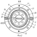
На фиг. 1 показан общий вид замка кодового; на фиг.2 - сечение А-А на фиг.1. In FIG. 1 shows a general view of the code lock; figure 2 is a section aa in figure 1.
Замок кодовый содержит ригель 1, кодовые элементы 2, шипы 3, стойки 4, пластины 5, крепежные элементы б, полости 7, пазы 9, 10, 25, стакан 11 с фланцем 14, крышку 12, ограничитель 13, стаканы внутренние 15, отверстия 16, 21, 8, 23, 24, фиксаторы 17, диск 18, рифления 19, днища 20, резьбовые элементы 22, кольца 26 и метки 27. The code lock contains a crossbar 1,
Ригель 1 (фиг. 1 и 2) выполнен из листового материала и установлен с возможностью санкционированного возвратно-поступательного ограниченного перемещения. На одной из боковых поверхностей ригеля 1 выполнены шипы 3. В нижней части ригеля 1 установлен ограничитель 13 в виде, например, винта. Кодовые элементы 2 выполнены в виде стаканов с отверстиями 23 и пазами 9. На наружной боковой поверхности кодовых элементов 2 выполнены рифления 19 и метки в виде равномерной шкалы с цифрами ( на фиг.условно позицией не обозначено). Кодовые элементы 2 установлены с возможностью поворота вокруг ригеля 1. Стойки 4 выполнены в виде элементов L-образной и I-образной формы с опорными частями и отверстиями. Между стойками 4 установлены две пластины 5 и скреплены между собой посредством крепежных элементов 6, например заклепок. Стойки 4, пластины 5 и крепежные элементы 6 образуют неразъемный корпус. В верхней части корпуса две пластины 5 имеют полости 7. Пластины 5 и стойки 4 формируют отверстие, в котором перемещается ригель 1. Полости 7 необходимы для обеспечения перемещения верхних шипов 3 на заданную величину "h". Отверстия 8 выполнены на кольцах 26. Пазы 10 выполнены на стаканах внутренних 15 и сообщены с отверстиями 24, выполненными также на стаканах внутренних 15. Стакан 11 с фланцем 14 установлен по центру ригеля 1 между крышкой 12 и корпусом. В днище стакана 11 выполнено отверстие ( на фиг. условно позицией не обозначено) по форме ригеля 1, посредством которого осуществляется центрирование ригеля 1. Крышка 12 также имеет отверстие по форме ригеля 1, посредством которого также осуществляется центрирование ригеля 1. Ограничитель 13 выполнен, например, в виде винта и закреплен к ригелю 1. Ограничитель 13 ограничивает перемещение ригеля 1. Ограничитель 13 расположен во внутренней полости стакана 11 между его днищем и поверхностью крышки 12. Стаканы внутренние 15 установлены во внутренних полостях кодовых элементов 2. На днищах 20 стаканов внутренних 15 выполнены отверстия 24 и пазы 10. На днищах 20 стаканов внутренних 15 также выполнены фиксаторы 17 посредством выдавки листового материала стаканов внутренних 15. Фиксаторы 17 кинематически взаимодействуют с отверстиями 16, выполненными на кодовых элементах 2. Фиксаторы 17 скрепляют кодовые элементы 2 со стаканами внутренними 15. Кодовые элементы 2 установлены с возможностью поворота совместно со стаканами внутренними 15. Диск 18 установлен в верхней части замка кодового и имеет отверстие по форме ригеля 1 и паз для обеспечения перемещения верхнего шипа 3. Диск 18 имеет также два паза 25, выполненных на наружной периферийной его части, которые кинематически взаимодействуют с пластинами 5. Рифления 19 выполнены на наружной поверхности каждого кодового диска 2. Функциональное назначение рифлении 19 - обеспечить качественное сцепление с поверхностью кодовых элементов 2 при их повороте. Отверстия 21 выполнены сквозными на опорных частях стоек 4, на фланцах 14 и на крышке 12 и предназначены для монтажа замка кодового к опорной поверхности, например, двери или сейфа. Резьбовые элементы 22 выполнены в виде винтов с потайной головкой и обеспечивают закрепление крышки 12 и стакана 11 с фланцем 14 к опорным частям стоек 4. Отверстия 23 выполнены на кодовых элементах 2. Отверстия 24 выполнены на днищах 20 стаканов внутренних 15. Пазы 25 выполнены на периферийных частях колец 26 и диска 18 и кинематически взаимодействуют с пластинами 5. Диск 18 и кольца 26 установлены с возможностью перемещения вдоль пластин 5. На каждом кольце 26 выполнено по одной метке 27. The crossbar 1 (Fig. 1 and 2) is made of sheet material and installed with the possibility of an authorized reciprocating limited movement. On one of the side surfaces of the crossbar 1 there are spikes 3. In the lower part of the crossbar 1 there is a limiter 13 in the form of, for example, a screw. The
Замок кодовый работает следующим образом. Code lock works as follows.
На фиг.1 и 2 показан замок кодовый в положении "закрыто", при этом нижняя часть ригеля 1 выступает за пределы крышки 12 (см. фиг.1). Figure 1 and 2 shows the code lock in the closed position, while the lower part of the crossbar 1 extends beyond the cover 12 (see figure 1).
Предположим, что необходимо выставить замок кодовый в положение "открыто". Обхватывают кодовые элементы 2 в зоне рифлений 19 и поворачивают их вокруг ригеля 1, совмещая нужные метки на поверхности кодовых элементов 2 с метками 27 (см. фиг.2), при этом пазы 9 и 10 совмещаются с шипами 3. Затем берутся за выступающую верхнюю часть ригеля 1 и перемещают его вверх до упора, при этом шипы 3 перемещаются сквозь пазы 9, 10 (а также сквозь паз, выполненный на диске 18) и отверстия 8. После перемещения ригеля 1 вверх шипы 3 перемещаются в пространство над кольцами 26 и диском 18, а ограничитель 13 вступает во взаимодействие с внутренней поверхностью стакана 11. Для фиксации ригеля 1 в крайнем верхнем положении необходимо повернуть кодовые элементы в любое произвольное положение и отвести тем самым пазы 9 и 10 из зоны шипов 3. Замок кодовый выставлен в положение "открыто". Suppose you want to set the code lock to the "open" position. They encircle the
Внутренние стаканы 15 с фиксаторами 17, кинематически взаимодействующими с отверстиями 16 на кодовых элементах 2, предотвращают несанкционированное определение "истинного" кода замка, при котором осуществляется открывание замка. The
Claims (1)
Priority Applications (1)
| Application Number | Priority Date | Filing Date | Title |
|---|---|---|---|
| RU2001112485A RU2193643C1 (en) | 2001-05-14 | 2001-05-14 | Coded lock |
Applications Claiming Priority (1)
| Application Number | Priority Date | Filing Date | Title |
|---|---|---|---|
| RU2001112485A RU2193643C1 (en) | 2001-05-14 | 2001-05-14 | Coded lock |
Publications (1)
| Publication Number | Publication Date |
|---|---|
| RU2193643C1 true RU2193643C1 (en) | 2002-11-27 |
Family
ID=20249387
Family Applications (1)
| Application Number | Title | Priority Date | Filing Date |
|---|---|---|---|
| RU2001112485A RU2193643C1 (en) | 2001-05-14 | 2001-05-14 | Coded lock |
Country Status (1)
| Country | Link |
|---|---|
| RU (1) | RU2193643C1 (en) |
Citations (7)
| Publication number | Priority date | Publication date | Assignee | Title |
|---|---|---|---|---|
| US3419893A (en) * | 1966-06-13 | 1968-12-31 | Emhart Corp | Permutation locks |
| US3906761A (en) * | 1974-08-26 | 1975-09-23 | Frank H Swaim | Disabling mechanism for a combination lock |
| DE1947557B2 (en) * | 1969-02-10 | 1976-12-16 | Presto Lock Co. Inc., Garfield, N.J. (V.St.A.) | PERMUTATION LOCK FOR CASE OR DGL. |
| DE2653193A1 (en) * | 1976-01-30 | 1977-08-04 | Kidde Co Presto Lock Div | COMBINATION LOCKED |
| DE3609443A1 (en) * | 1986-03-20 | 1987-09-24 | Franzen Soehne S | Combination lock with a secret-code resetting device |
| EP0246980A1 (en) * | 1986-05-22 | 1987-11-25 | Etablissements THIRARD | Combination padlock |
| RU2161684C1 (en) * | 2000-04-14 | 2001-01-10 | Максимов Александр Иванович | Door and code lock; door fabrication method |
-
2001
- 2001-05-14 RU RU2001112485A patent/RU2193643C1/en active
Patent Citations (7)
| Publication number | Priority date | Publication date | Assignee | Title |
|---|---|---|---|---|
| US3419893A (en) * | 1966-06-13 | 1968-12-31 | Emhart Corp | Permutation locks |
| DE1947557B2 (en) * | 1969-02-10 | 1976-12-16 | Presto Lock Co. Inc., Garfield, N.J. (V.St.A.) | PERMUTATION LOCK FOR CASE OR DGL. |
| US3906761A (en) * | 1974-08-26 | 1975-09-23 | Frank H Swaim | Disabling mechanism for a combination lock |
| DE2653193A1 (en) * | 1976-01-30 | 1977-08-04 | Kidde Co Presto Lock Div | COMBINATION LOCKED |
| DE3609443A1 (en) * | 1986-03-20 | 1987-09-24 | Franzen Soehne S | Combination lock with a secret-code resetting device |
| EP0246980A1 (en) * | 1986-05-22 | 1987-11-25 | Etablissements THIRARD | Combination padlock |
| RU2161684C1 (en) * | 2000-04-14 | 2001-01-10 | Максимов Александр Иванович | Door and code lock; door fabrication method |
Similar Documents
| Publication | Publication Date | Title |
|---|---|---|
| US4073172A (en) | High security deadbolt lock | |
| RU2161684C1 (en) | Door and code lock; door fabrication method | |
| US4068505A (en) | Locking device | |
| US20140311390A1 (en) | Safe and Lock Mechanism | |
| US20150159410A1 (en) | Lock Assembly with Locking Handle | |
| US6082272A (en) | Safe for supporting a bed | |
| CA2878539A1 (en) | Dual cam lock apparatus | |
| AU2013346669B2 (en) | Mechanism for opening cam locks by means of electronic clutch cylinders | |
| RU2370612C1 (en) | Protective cover plate for cylinder mechanism | |
| EP0452282A3 (en) | Mechanism designed to ensure that actuators for automatically locking and unlocking automobile doors have no load at the end of their movement run | |
| US1854839A (en) | Safe | |
| CN203654895U (en) | Keyhole protective device comprising cam and dial disk | |
| US4532870A (en) | Safe apparatus | |
| RU2245978C2 (en) | Door | |
| RU2162129C1 (en) | Method for assembly of door handle and door handle | |
| US1967779A (en) | Closure member | |
| RU185252U1 (en) | Small-sized household safe | |
| RU2244085C2 (en) | Method for manufacture of combination lock and combination lock | |
| RU2193087C1 (en) | Coded lock | |
| RU2200224C1 (en) | Manner to close keyhole and device closing keyhole | |
| RU2414571C1 (en) | Blocking device for door lock | |
| RU2166048C1 (en) | Method of closing keyhole and metal door | |
| RU2192529C1 (en) | Code lock | |
| KR200440287Y1 (en) | Lock on sliding windows | |
| RU2186918C1 (en) | Method for manufacture of lock and lock |