RU2166048C1 - Method of closing keyhole and metal door - Google Patents
Method of closing keyhole and metal door Download PDFInfo
- Publication number
- RU2166048C1 RU2166048C1 RU2000119200/12A RU2000119200A RU2166048C1 RU 2166048 C1 RU2166048 C1 RU 2166048C1 RU 2000119200/12 A RU2000119200/12 A RU 2000119200/12A RU 2000119200 A RU2000119200 A RU 2000119200A RU 2166048 C1 RU2166048 C1 RU 2166048C1
- Authority
- RU
- Russia
- Prior art keywords
- keyhole
- hinge
- movable part
- closing
- shaped
- Prior art date
Links
Images
Landscapes
- Hinges (AREA)
Abstract
Description
Изобретения относятся к способам для закрывания замочной скважины и металлическим дверям и могут быть широко использованы для замков любых конструкций, имеющих замочную скважину для предотвращения несанкционированного доступа. The invention relates to methods for closing a keyhole and metal doors and can be widely used for locks of any structure having a keyhole to prevent unauthorized access.
Известен способ закрывания замочной скважины, включающий перемещение материального тела в зону замочной скважины, причем в качестве материального тела используют дверную ручку (патент N 2140514, Россия, 1999 г., E 05 B 17/14) - аналог. A known method of closing a keyhole, including moving the material body into the keyhole zone, wherein the door handle is used as the material body (patent N 2140514, Russia, 1999, E 05 B 17/14) is an analogue.
Известно устройство для закрывания замочной скважины, содержащее корпус с отверстием, заслонку и крепежные элементы (патент N 2140514, Россия, 1999 г., E 05 B 17/14) - аналог. A device for closing a keyhole, comprising a housing with a hole, a shutter and fasteners (patent N 2140514, Russia, 1999, E 05 B 17/14) is an analogue.
Известен также способ закрывания замочной скважины, заключающийся в перемещении материального тела в зону замочной скважины (патент N 2147659, Россия, 2000 г., E 05 B 17/14) - прототип. There is also a method of closing a keyhole, which consists in moving the material body into the keyhole zone (patent N 2147659, Russia, 2000, E 05 B 17/14) - prototype.
Известна также металлическая дверь, содержащая коробку, дверное полотно с отверстием для элемента замка с замочной скважиной, замок с замочной скважиной и петли, выполненные в виде отдельных частей, шарнирно скрепленных между собой (патент N 2147659, Россия, 2000 г., E 06 B 5/06) - прототип. Also known is a metal door containing a box, a door leaf with an opening for a lock element with a keyhole, a lock with a keyhole and hinges made in the form of separate parts pivotally fastened together (patent N 2147659, Russia, 2000, E 06 B 5/06) - prototype.
Задача, на решение которой направлено заявляемое техническое решение по объекту "Способ закрывания замочной скважины", состоит в расширении арсенала технических средств для способов закрывания замочной скважины. The problem, which is aimed by the claimed technical solution for the object "Method of closing a keyhole", is to expand the arsenal of technical means for methods of closing a keyhole.
Задача, на решение которой направлено заявляемое техническое решение по объекту "Металлическая дверь", состоит в расширении функциональных возможностей объекта и расширение арсенала технических средств для закрывания замочной скважины. The problem to which the claimed technical solution is directed for the Metal Door facility is to expand the facility's functionality and expand the arsenal of technical means for closing the keyhole.
Технический результат, который может быть получен при осуществлении способа, заключается в расширении арсенала технических средств для способа закрывания замочной скважины. The technical result that can be obtained by implementing the method is to expand the arsenal of technical means for the method of closing a keyhole.
Технический результат, который может быть получен при осуществлении устройства, заключается в расширении функциональных возможностей устройства и расширении арсенала технических средств для закрывания замочной скважины. The technical result that can be obtained by implementing the device is to expand the functionality of the device and expand the arsenal of technical means for closing the keyhole.
Поставленная задача в способе достигается за счет использования в качестве материального тела для закрывания замочной скважины подвижной части петли. The task in the method is achieved through the use of a movable part of the loop as a material body for closing the keyhole.
Поставленная задача в устройстве достигается за счет того, что одна из частей петли установлена с возможностью фиксированного перемещения по поверхности дверного полотна и определенной взаимосвязью деталей устройства. The task in the device is achieved due to the fact that one of the parts of the hinge is installed with the possibility of fixed movement on the surface of the door leaf and a certain relationship of the parts of the device.
Сущность заявляемого способа заключается в том, что в способе закрывания замочной скважины, включающем закрывание замочной скважины путем перемещения материального тела в зону замочной скважины, согласно изобретению в нем в качестве материального тела используют подвижную часть петли. The essence of the proposed method lies in the fact that in the method of closing the keyhole, including closing the keyhole by moving the material body into the zone of the keyhole, according to the invention, the movable part of the loop is used as the material body in it.
Сущность заявляемого устройства заключается в том, что металлическая дверь, содержащая коробку, дверное полотно с отверстием для элемента замка с замочной скважиной, замок с замочной скважиной и петли, согласно изобретению по меньшей мере одна из частей петли установлена с возможностью фиксированного перемещения по поверхности дверного полотна. На подвижной части петли выполнено по меньшей мере одно отверстие для элемента замка с замочной скважиной. Величина перемещения подвижной части петли равна расстоянию между центром отверстия в дверном полотне для элемента замка с замочной скважиной и центром отверстия в подвижной части петли для элемента замка с замочной скважиной. The essence of the claimed device lies in the fact that a metal door containing a box, a door leaf with an opening for a lock element with a keyhole, a lock with a keyhole and hinges, according to the invention, at least one part of the hinge is installed with the possibility of fixed movement on the surface of the door leaf . At least one opening for a lock element with a keyhole is made on the movable part of the loop. The amount of movement of the movable part of the hinge is equal to the distance between the center of the hole in the door leaf for the lock element with the keyhole and the center of the hole in the movable part of the hinge for the lock element with the keyhole.
Сопоставительный анализ заявляемого способа с прототипом показывает, что заявляемый способ закрывания замочной скважины имеет общие признаки с прототипом:
осуществляют перемещение материального тела в зону замочной скважины.A comparative analysis of the proposed method with the prototype shows that the inventive method of closing the keyhole has common features with the prototype:
carry out the movement of the material body in the keyhole zone.
Заявляемый способ отличается от прототипа новыми признаками:
в качестве материального тела используют подвижную часть петли.The inventive method differs from the prototype with new features:
as a material body use the movable part of the loop.
Сопоставительный анализ заявляемого устройства с прототипом показывает, что заявляемое устройство (металлическая дверь) имеет общие признаки с прототипом:
коробка;
дверное полотно с отверстием для элемента замка с замочной скважиной;
замок с замочной скважиной;
петли, выполненные в виде отдельных частей, шарнирно скрепленных между собой.A comparative analysis of the claimed device with the prototype shows that the claimed device (metal door) has common features with the prototype:
box;
door leaf with an opening for a lock element with a keyhole;
keyhole lock;
hinges made in the form of separate parts pivotally fastened together.
Заявляемое устройство отличается от прототипа новыми признаками:
по меньшей мере одна из частей петли установлена с возможностью фиксированного перемещения по поверхности дверного полотна;
на подвижной части петли выполнено по меньшей мере одно отверстие для элемента замка с замочной скважиной;
величина перемещения подвижной части петли равна расстоянию между центром отверстия в дверном полотне для элемента замка с замочной скважиной и центром отверстия в подвижной части петли для элемента замка с замочной скважиной;
подвижная часть петли выполнена Г-образной формы или Т-образной формы, или Y-образной формы.The inventive device differs from the prototype with new features:
at least one part of the hinge is installed with the possibility of a fixed movement on the surface of the door leaf;
at least one opening for a lock element with a keyhole is made on the movable part of the loop;
the amount of movement of the movable part of the hinge is equal to the distance between the center of the hole in the door leaf for the castle element with the keyhole and the center of the hole in the movable part of the hinge for the castle element with the keyhole;
the movable part of the loop is L-shaped or T-shaped, or Y-shaped.
Из приведенного перечня признаков заявляемого способа и достижения поставленной задачи наглядно видно, что заявляемое техническое решение представляет собой новую совокупность признаков, как сочетание известных и новых признаков, обеспечивающих получение нового технического результата, не известного на дату подачи заявки. Новый технический результат, который может быть получен при осуществлении изобретения, заключается в расширении арсенала технических средств для способа закрывания замочной скважины. From the above list of features of the proposed method and the achievement of the task it is clearly seen that the claimed technical solution is a new set of features, as a combination of known and new features, providing a new technical result, not known at the filing date of the application. A new technical result that can be obtained by carrying out the invention is to expand the arsenal of technical means for the method of closing a keyhole.
Из приведенного перечня признаков заявляемого устройства и достижения поставленной задачи наглядно видно, что заявляемое техническое решение представляет собой новую совокупность признаков как сочетание известных и новых признаков, обеспечивающих получение нового технического результата, не известного на дату подачи заявки. Новый технический результат, который может быть получен при осуществлении изобретения, заключается в расширении арсенала технических средств и в расширении функциональных возможностей для металлической двери. From the above list of features of the claimed device and the achievement of the task it is clearly seen that the claimed technical solution is a new combination of features as a combination of known and new features, providing a new technical result, not known at the filing date of the application. A new technical result that can be obtained by carrying out the invention is to expand the arsenal of technical means and to expand the functionality for a metal door.
Заявляемые изобретения связаны между собой настолько, что образуют единый изобретательский замысел. The claimed inventions are so interconnected that they form a single inventive concept.
Предлагаемый способ промышленно применим, т.к. он может быть использован в строительстве, промышленности, сельском хозяйстве и других отраслях народного хозяйства, где используются способы закрывания замочной скважины. The proposed method is industrially applicable, because it can be used in construction, industry, agriculture and other sectors of the economy, where keyhole closure methods are used.
Предлагаемое устройство промышленно применимо, т.к. оно может быть использовано в строительстве, промышленности, сельском хозяйстве и других отраслях народного хозяйства, где используются металлические двери. The proposed device is industrially applicable, because it can be used in construction, industry, agriculture and other sectors of the economy where metal doors are used.
Техническое решение заявляемого способа соответствует критерию "новизна", т. к. он не известен из уровня техники на дату подачи заявки. Не известна из уровня техники совокупность существенных признаков заявляемого технического решения и их влияние на получение требуемого технического результата. The technical solution of the proposed method meets the criterion of "novelty", because it is not known from the prior art at the date of application. Not known from the prior art, the set of essential features of the claimed technical solution and their impact on obtaining the desired technical result.
Техническое решение заявляемого устройства соответствует критерию "новизна", т.к. оно не известно из уровня техники на дату подачи заявки. Не известна из уровня техники совокупность существенных признаков заявляемого технического решения и их влияние на получение требуемого технического результата. The technical solution of the claimed device meets the criterion of "novelty", because it is not known from the prior art at the filing date of the application. Not known from the prior art, the set of essential features of the claimed technical solution and their impact on obtaining the desired technical result.
Техническое решение заявляемого способа соответствует критерию "изобретательский уровень", т.к. не выявлены решения, имеющие признаки, совпадающие с его отличительными признаками, и не обнаружена известность влияния отличительных признаков на получаемый технический результат. The technical solution of the proposed method meets the criterion of "inventive step", because no solutions having features matching its distinctive features have been identified, and the influence of the distinctive features on the resulting technical result is not known.
Техническое решение заявляемого устройства соответствует критерию "изобретательский уровень", т.к. не выявлены решения, имеющие признаки, совпадающие с его отличительными признаками, и не обнаружена известность влияния отличительных признаков на получаемый технический результат. The technical solution of the claimed device meets the criterion of "inventive step", because no solutions having features matching its distinctive features have been identified, and the influence of the distinctive features on the resulting technical result is not known.
Таким образом, заявляемые технические решения "cпособ..." и "металлическая дверь" соответствуют всем предъявляемым к изобретению критериям и связаны между собой настолько, что они образуют единый изобретательский замысел и обеспечивают получение нового технического результата. Thus, the claimed technical solutions "method ..." and "metal door" correspond to all the criteria for the invention and are so interconnected that they form a single inventive concept and provide a new technical result.
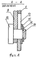
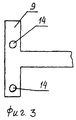
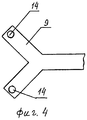
На фиг. 1 показан общий вид металлической двери для реализации способа закрывания замочной скважины; на фиг. 2 - сечение А-А на фиг. 1; на фиг. 3 и фиг. 4 - варианты исполнения подвижной части петли. In FIG. 1 shows a general view of a metal door for implementing a keyhole closing method; in FIG. 2 is a section AA in FIG. 1; in FIG. 3 and FIG. 4 - embodiments of the movable part of the loop.
Металлическая дверь содержит дверное полотно 1, коробку 2, ручку 3, замок с замочной скважиной 4, подвижные части петли 5, 9, неподвижные части петли 6, 10, оси 7, 11, крепежные элементы 8, фиксаторы 12, направляющие 13, отверстие для элемента замка с замочной скважиной 14 (отверстие выполнено на подвижной части петли 9), отверстие в дверном полотне для элемента замка с замочной скважиной (отверстие условно не обозначено позицией, т.к. в отверстие входит часть замка с замочной скважиной 4), шайбу 15, стопорное кольцо 16 и канавку 17. The metal door comprises a door leaf 1, a box 2, a handle 3, a lock with a keyhole 4, movable parts of the
Металлическая дверь имеет три петли - верхнюю, среднюю и нижнюю. Верхняя и нижняя петли имеют одинаковую конструкцию. Подвижная часть петли 5 (см. фиг. 1) жестко закреплена к поверхности дверного полотна 1 посредством крепежных элементов 8 и установлена с возможностью поворота вокруг оси 7. Неподвижная часть петли 6 жестко прикреплена к поверхности коробки 2. Ручка 3 закреплена к поверхности дверного полотна 1. Замок с замочной скважиной 4 размещен так, что часть замка с замочной скважиной размещена в отверстии, которое выполнено в дверном полотне (позиция отверстия условно не показана). Подвижная часть петли 9, средней, установлена с возможностью перемещения по поверхности дверного полотна 1 и с возможностью поворота вокруг оси 11. Неподвижная часть петли 10 закреплена к поверхности коробки 2. На поверхности подвижной части петли выполнено отверстие 14 для элемента замка с замочной скважиной. Фиксаторы 12 жестко закреплены к подвижной части петли 9 и установлены с возможностью перемещения совместно с подвижной частью петли 9 вдоль направляющих 13. Направляющие 13 выполнены на поверхности дверного полотна 1 в виде отверстий вытянутой формы. На поверхности фиксатора 12 выполнена канавка 17 (см. фиг. 2) в которой смонтирована стопорная шайба 16. Между стопорной шайбой 16 и дверным полотном 1 размещена шайба 15. The metal door has three hinges - upper, middle and lower. The upper and lower hinges have the same design. The movable part of the hinge 5 (see Fig. 1) is rigidly fixed to the surface of the door leaf 1 by means of fasteners 8 and mounted to rotate around the axis 7. The fixed part of the hinge 6 is rigidly attached to the surface of the box 2. The handle 3 is fixed to the surface of the door leaf 1 The lock with keyhole 4 is placed so that part of the lock with keyhole is placed in the hole that is made in the door leaf (the position of the hole is not shown conventionally). The movable part of the
При установке на дверное полотно 1 двух замков с замочными скважинами используют подвижную часть петли 9 Т-образной или Y-образной формы (см. фиг. 3 и 4). Это делают для того, чтобы обеспечить одновременное закрывание двух замочных скважин замков. При закрывании одной замочной скважины используют подвижную часть петли Г-образной формы (см. фиг. 1). When installing on the door leaf 1 two locks with keyholes, the movable part of the
Способ реализуется следующим образом. The method is implemented as follows.
На фиг. 1 показан общий вид металлической двери в закрытом положении, при этом замочная скважина замка 4 закрыта подвижной частью петли 9 (см. фиг. 1). Для открывания двери перемещают подвижную часть петли 9 вверх до упора, при этом отверстие для элемента замка с замочной скважиной 14 совместится с отверстием в дверном полотне для элемента замка с замочной скважиной, а фиксаторы переместятся до упора вверх вдоль направляющих 13. Направляющие 13 обеспечивают фиксированное перемещение подвижной части петли 9 на величину, равную межосевому расстоянию между центрами отверстия 14 и отверстия в дверном полотне 1 под замочную скважину замка 4. После того как переместили подвижную часть петли 9, берут ключ, вводят его в замочную скважину замка и открывают замок. Вынимают ключ из замочной скважины замка 4 и перемещают подвижную часть петли 9 вниз. Затем берутся за ручку 3 и поворачивают дверное полотно 1 совместно с подвижными частями петель 5 и 9 вокруг осей 7 и 11. In FIG. 1 shows a General view of the metal door in the closed position, while the keyhole of the lock 4 is closed by the movable part of the loop 9 (see Fig. 1). To open the door, move the movable part of the
Работа устройства описана при описании реализации способа. The operation of the device is described in the description of the implementation of the method.
Таким образом, заявляемые технические решения "способ закрывания замочной скважины" и "металлическая дверь" обеспечивают достижение поставленной задачи и получение нового технического результата. Thus, the claimed technical solutions "method of closing the keyhole" and "metal door" ensure the achievement of the task and a new technical result.
Claims (3)
Priority Applications (1)
| Application Number | Priority Date | Filing Date | Title |
|---|---|---|---|
| RU2000119200/12A RU2166048C1 (en) | 2000-07-20 | 2000-07-20 | Method of closing keyhole and metal door |
Applications Claiming Priority (1)
| Application Number | Priority Date | Filing Date | Title |
|---|---|---|---|
| RU2000119200/12A RU2166048C1 (en) | 2000-07-20 | 2000-07-20 | Method of closing keyhole and metal door |
Publications (1)
| Publication Number | Publication Date |
|---|---|
| RU2166048C1 true RU2166048C1 (en) | 2001-04-27 |
Family
ID=20238078
Family Applications (1)
| Application Number | Title | Priority Date | Filing Date |
|---|---|---|---|
| RU2000119200/12A RU2166048C1 (en) | 2000-07-20 | 2000-07-20 | Method of closing keyhole and metal door |
Country Status (1)
| Country | Link |
|---|---|
| RU (1) | RU2166048C1 (en) |
Cited By (2)
| Publication number | Priority date | Publication date | Assignee | Title |
|---|---|---|---|---|
| RU2204005C1 (en) * | 2001-10-09 | 2003-05-10 | Максимов Александр Иванович | Method of door manufacture |
| RU2205267C1 (en) * | 2001-12-03 | 2003-05-27 | Максимов Александр Иванович | Method of door manufacture, door, method of door locking system manufacture and door locking system |
Citations (5)
| Publication number | Priority date | Publication date | Assignee | Title |
|---|---|---|---|---|
| CH94181A (en) * | 1921-06-13 | 1922-04-17 | Wenger Hans | Lock security. |
| DE3033585A1 (en) * | 1980-09-06 | 1982-03-25 | Heinrich 3550 Marburg Sälzer | Bullet proof intruder resistant keyhole plate cover - has tongues fitting two angled parallel grooves cut into plate |
| DE3837427A1 (en) * | 1988-11-04 | 1990-05-10 | Sicherheit Und Service Inh Kla | Device for securing the visible key opening in locks |
| WO1991003614A1 (en) * | 1989-08-31 | 1991-03-21 | Tetsurou Makita | Lock with cover |
| RU2147659C1 (en) * | 1999-08-20 | 2000-04-20 | Максимов Александр Иванович | Method of closing key hole, and metal door |
-
2000
- 2000-07-20 RU RU2000119200/12A patent/RU2166048C1/en not_active IP Right Cessation
Patent Citations (5)
| Publication number | Priority date | Publication date | Assignee | Title |
|---|---|---|---|---|
| CH94181A (en) * | 1921-06-13 | 1922-04-17 | Wenger Hans | Lock security. |
| DE3033585A1 (en) * | 1980-09-06 | 1982-03-25 | Heinrich 3550 Marburg Sälzer | Bullet proof intruder resistant keyhole plate cover - has tongues fitting two angled parallel grooves cut into plate |
| DE3837427A1 (en) * | 1988-11-04 | 1990-05-10 | Sicherheit Und Service Inh Kla | Device for securing the visible key opening in locks |
| WO1991003614A1 (en) * | 1989-08-31 | 1991-03-21 | Tetsurou Makita | Lock with cover |
| RU2147659C1 (en) * | 1999-08-20 | 2000-04-20 | Максимов Александр Иванович | Method of closing key hole, and metal door |
Cited By (2)
| Publication number | Priority date | Publication date | Assignee | Title |
|---|---|---|---|---|
| RU2204005C1 (en) * | 2001-10-09 | 2003-05-10 | Максимов Александр Иванович | Method of door manufacture |
| RU2205267C1 (en) * | 2001-12-03 | 2003-05-27 | Максимов Александр Иванович | Method of door manufacture, door, method of door locking system manufacture and door locking system |
Similar Documents
| Publication | Publication Date | Title |
|---|---|---|
| RU2163289C1 (en) | Door manufacturing method; door and door-handle | |
| US3751948A (en) | Protective lock casing | |
| US4673202A (en) | Door locking device | |
| US3888096A (en) | Lock-up housing for door lock | |
| RU2161684C1 (en) | Door and code lock; door fabrication method | |
| KR20080095832A (en) | Door security device | |
| US20140033639A1 (en) | Low profile security system for canine entry and exit | |
| US3817062A (en) | Lock device for securing an apertured member | |
| US4997219A (en) | Multi-lock latch | |
| EP0835358A1 (en) | Bolt unit and frame arrangement | |
| US4286814A (en) | Universally pivotal padlock and staple shielding hasp | |
| US5623841A (en) | Two-way locking system and method | |
| RU2040690C1 (en) | Safe | |
| US7387076B2 (en) | Locking system for a door of an enclosure | |
| RU2222677C2 (en) | Sliding locking bolt | |
| RU2140514C1 (en) | Method for closing of keyhole and device for its realization | |
| RU2147659C1 (en) | Method of closing key hole, and metal door | |
| US5280976A (en) | Door security device | |
| US4093284A (en) | Door construction | |
| US4962954A (en) | Burglar bar system incorporating a hand operated latch mechanism operable from the building interior | |
| EP3461976B1 (en) | Improved door locking mechanism | |
| RU2095536C1 (en) | Locking system | |
| KR830003638A (en) | Auto cross bolt double lock | |
| RU2087660C1 (en) | Locking device for garage gate | |
| RU2162129C1 (en) | Method for assembly of door handle and door handle |
Legal Events
| Date | Code | Title | Description |
|---|---|---|---|
| MM4A | The patent is invalid due to non-payment of fees |
Effective date: 20050721 |