RU2145683C1 - Transmission mechanisms for transport facility and method of control of this mechanism - Google Patents
Transmission mechanisms for transport facility and method of control of this mechanism Download PDFInfo
- Publication number
- RU2145683C1 RU2145683C1 RU97104209/28A RU97104209A RU2145683C1 RU 2145683 C1 RU2145683 C1 RU 2145683C1 RU 97104209/28 A RU97104209/28 A RU 97104209/28A RU 97104209 A RU97104209 A RU 97104209A RU 2145683 C1 RU2145683 C1 RU 2145683C1
- Authority
- RU
- Russia
- Prior art keywords
- force
- transmission mechanism
- mechanism according
- applying
- teeth
- Prior art date
Links
Images
Classifications
-
- F—MECHANICAL ENGINEERING; LIGHTING; HEATING; WEAPONS; BLASTING
- F16—ENGINEERING ELEMENTS AND UNITS; GENERAL MEASURES FOR PRODUCING AND MAINTAINING EFFECTIVE FUNCTIONING OF MACHINES OR INSTALLATIONS; THERMAL INSULATION IN GENERAL
- F16H—GEARING
- F16H63/00—Control outputs from the control unit to change-speed- or reversing-gearings for conveying rotary motion or to other devices than the final output mechanism
- F16H63/02—Final output mechanisms therefor; Actuating means for the final output mechanisms
- F16H63/30—Constructional features of the final output mechanisms
- F16H63/3023—Constructional features of the final output mechanisms the final output mechanisms comprising elements moved by fluid pressure
- F16H63/3026—Constructional features of the final output mechanisms the final output mechanisms comprising elements moved by fluid pressure comprising friction clutches or brakes
-
- F—MECHANICAL ENGINEERING; LIGHTING; HEATING; WEAPONS; BLASTING
- F16—ENGINEERING ELEMENTS AND UNITS; GENERAL MEASURES FOR PRODUCING AND MAINTAINING EFFECTIVE FUNCTIONING OF MACHINES OR INSTALLATIONS; THERMAL INSULATION IN GENERAL
- F16H—GEARING
- F16H61/00—Control functions within control units of change-speed- or reversing-gearings for conveying rotary motion ; Control of exclusively fluid gearing, friction gearing, gearings with endless flexible members or other particular types of gearing
- F16H61/02—Control functions within control units of change-speed- or reversing-gearings for conveying rotary motion ; Control of exclusively fluid gearing, friction gearing, gearings with endless flexible members or other particular types of gearing characterised by the signals used
- F16H61/0293—Control functions within control units of change-speed- or reversing-gearings for conveying rotary motion ; Control of exclusively fluid gearing, friction gearing, gearings with endless flexible members or other particular types of gearing characterised by the signals used the signals being purely mechanical
- F16H61/0295—Automatic gear shift control, e.g. initiating shift by centrifugal forces
Abstract
Description
Изобретение относится к механизму автоматической трансмиссии, в особенности для транспортного средства, имеющему по меньшей мере две передачи. The invention relates to an automatic transmission mechanism, in particular for a vehicle having at least two gears.
Настоящее изобретение также относится к способу управления таким механизмом. The present invention also relates to a method for controlling such a mechanism.
В международной публикации WO-A-9207206 описана автоматическая трансмиссия, в которой муфта избирательно соединяет два вращающихся элемента дифференциала, такого как, например, эпициклическая передача, в зависимости от того, какая из двух противодействующих сил больше. Такими силами являются, например, осевая сила, вызываемая подвижным в осевом направлении косозубым цилиндрическим зубчатым колесом и способствующая освобождению муфты против действия пружин, и/или сила, вызванная центробежными тахометрическими средствами и способствующая включению муфты. При разъединенном состоянии муфты необходимо предотвратить вращение третьего вращающегося элемента дифференциала, что может быть обеспечено посредством муфты свободного хода, предотвращающей вращение этого элемента в обратном направлении. International publication WO-A-9207206 describes an automatic transmission in which a clutch selectively couples two rotating differential elements, such as, for example, an epicyclic gear, depending on which of the two opposing forces is greater. Such forces are, for example, the axial force caused by the axially movable helical gear and contributing to the release of the clutch against the action of the springs, and / or the force caused by centrifugal tachometric means and contributing to the inclusion of the clutch. When the clutch is disconnected, it is necessary to prevent the rotation of the third rotating differential element, which can be achieved by means of a freewheel preventing the rotation of this element in the opposite direction.
Такой тип трансмиссии имеет ряд преимуществ, так как для его основного функционирования не требуются внешний источник энергии, датчики и схема управления. Это и есть механизм трансмиссии, который создает силы, управляющие им и одновременно являющиеся критериями для параметров, необходимых для управления. This type of transmission has several advantages, since its main operation does not require an external energy source, sensors and control circuit. This is the transmission mechanism, which creates the forces that control it and at the same time are the criteria for the parameters necessary for control.
Однако такой механизм трансмиссии непосредственно не обеспечивает возможность оптимизации процесса притормаживания, то есть, когда педаль акселератора отпущена, двигатель создает определенное торможение транспортного средства. В этом случае устойчивый крутящий момент двигателя уже не зависит ни от чего, кроме скорости вращения, и потому не является показателем торможения, необходимого водителю. Кроме того, в случае, когда крутящий момент определяется реакцией винтовых зубьев, последняя изменяет направление в процессе притормаживания и, следовательно, уже не стремится разъединить муфту. Кроме того, когда в конструкции имеется муфта свободного хода, даже если реакция зубьев обеспечивает возможность разъединения муфты, при создании таким образом одного из условий для работы с понижением скорости, другое условие остается не выполненным: в процессе притормаживания третий вращающийся элемент дифференциала стремится вращаться не в обратном направлении, а в нормальном и с высокой скоростью, что не может предотвратить муфта свободного хода. However, such a transmission mechanism does not directly provide an opportunity to optimize the braking process, that is, when the accelerator pedal is released, the engine creates a certain braking effect on the vehicle. In this case, the stable engine torque no longer depends on anything other than the rotation speed, and therefore is not an indication of the braking required by the driver. In addition, in the case where the torque is determined by the reaction of the helical teeth, the latter changes direction during braking and, therefore, no longer seeks to disconnect the clutch. In addition, when the design has a freewheel, even if the reaction of the teeth allows the coupling to be disconnected, thus creating one of the conditions for working with lowering speed, another condition remains unfulfilled: during braking, the third rotating differential element tends to rotate not in the opposite direction, but in normal and high speed, which cannot prevent the freewheel.
В международной публикации WО 94/19629, опубликованной после даты приоритета данного изобретения, описывается возможность избирательного добавления дополнительной силы для обеспечения процесса притормаживания и, в некоторых других случаях, для работы механизма трансмиссии с передаточным отношением, отличающимся от отношения, которое может получиться при сопоставлении двух основных противодействующих сил. Таким образом, когда водитель транспортного средства полностью выжимает педаль акселератора, возможна работа механизма трансмиссии с меньшим передаточным отношением даже при скоростях, при которых, например, центробежная сила, пропорциональная квадрату скорости, в обычных условиях вызвала бы работу с более высоким передаточным отношением. In the international publication WO 94/19629, published after the priority date of the present invention, describes the possibility of selectively adding additional force to ensure the braking process and, in some other cases, for the operation of the transmission mechanism with a gear ratio different from the ratio that can result from a comparison of two main opposing forces. Thus, when the driver of the vehicle fully depresses the accelerator pedal, it is possible to operate the transmission mechanism with a lower gear ratio even at speeds at which, for example, a centrifugal force proportional to the square of the speed would, under normal conditions, cause work with a higher gear ratio.
Существует проблема появления ударов во время изменения передачи. Например, возникновение такого удара возможно, если водитель случайно отпускает педаль акселератора, и при переходе механизма трансмиссии с более низкого передаточного отношения на более высокое появляется центробежная сила. В этом случае возникающее превосходство центробежной силы стремительно растет, и внезапно может произойти переключение механизма сцепления в положение сцепления. То же самое возможно, когда процесс управления вызывает изменение дополнительной силы, например вызывает ее исчезновение. There is a problem of impacts during a gear change. For example, the occurrence of such a blow is possible if the driver accidentally releases the accelerator pedal, and when the transmission mechanism moves from a lower gear ratio to a higher gear, a centrifugal force appears. In this case, the resulting superiority of centrifugal force is growing rapidly, and suddenly the clutch mechanism can switch to the clutch position. The same is possible when the control process causes a change in additional force, for example, causes its disappearance.
В патенте США A-4 713 984 описан механизм трансмиссии, в котором муфты управляются не силами, одна из которых может служить критерием для рабочего параметра, а только лишь гидравлическими приводами, управляемыми средствами выбора трансмиссии. Для предотвращения ударов путем ограничения скоростей потока масла при создании давления в гидравлических камерах и при их опорожнении предусмотрены специальные средства. US patent A-4 713,984 describes a transmission mechanism in which the couplings are not driven by forces, one of which can serve as a criterion for an operating parameter, but only by hydraulic drives controlled by transmission selection means. Special means are provided to prevent shock by limiting the flow rates of the oil when pressurizing the hydraulic chambers and when emptying them.
В аналогичной конструкции, описанной в европейском патенте EP-A-0149012, поперечное сечение канала, через которое проходит масло, изменяется в зависимости от скорости транспортного средства. In a similar design described in European patent EP-A-0149012, the cross section of the channel through which the oil passes varies depending on the speed of the vehicle.
Целью настоящего изобретения является создание механизма трансмиссии, в котором избирательные соединительные средства управляются переменными противодействующими силами и в котором отсутствуют удары, возможные во время изменения передаточного отношения. The aim of the present invention is to provide a transmission mechanism in which selective connecting means are controlled by variable opposing forces and in which there are no shocks possible during a gear ratio change.
Предлагаемый механизм трансмиссии содержит комбинацию групп зубьев, находящихся во взаимном зацеплении, и фрикционные соединительные средства, в которых подвижной включающий элемент подвергается воздействию средств приложения противодействующей силы, из которых по меньшей мере одно обеспечивает приложение к подвижному включающему элементу силы, являющейся критерием рабочего параметра, относящегося к автоматическому выбору передаточного отношения, причем указанная комбинация зубьев обеспечивает два различных передаточных отношения в соответствии с соединенным или разъединенным состоянием фрикционных соединительных средств, при этом механизм трансмиссии снабжен средствами амортизации ударов, установленными с возможностью торможения по меньшей мере некоторых перемещений подвижного включающего элемента между соединенным и разъединенным состояниями фрикционных соединительных средств. The proposed transmission mechanism contains a combination of groups of teeth that are in mutual engagement, and friction connecting means in which the movable switching element is exposed to the means of applying a counteracting force, of which at least one provides a force, which is the criterion of the operating parameter, related to the moving including element to the automatic gear ratio selection, wherein said tooth combination provides two different gear ratios in accordance with the connected or disconnected state of the friction coupling means, wherein the transmission mechanism is equipped with shock absorbing means that are capable of braking at least some movements of the movable switching element between the connected and disconnected states of the friction coupling means.
Средства амортизации предотвращают возникновение ударов путем торможения подвижного включающего элемента, особенно в указанных выше случаях. Cushioning means prevent the occurrence of shock by braking the movable switching element, especially in the above cases.
Средства приложения противодействующей силы предпочтительно содержат приспособление для приложения регулируемой силы, подающее в механизм трансмиссии силу, которая имитирует увеличение или повторное появление одной из противодействующих сил, обычно управляющих механизмом, чтобы тем самым в большей степени способствовать работе механизма с одним передаточным отношением по сравнению с автоматическим управлением только основными средствами приложения противодействующей силы. Means for applying a counter force preferably comprise a device for applying a controlled force, which feeds into the transmission mechanism a force that simulates the increase or reappearance of one of the counter forces, which usually control the mechanism, in order to thereby contribute to a greater extent the operation of the mechanism with one gear ratio compared to an automatic control only the main means of application of the opposing force.
Если приспособление для приложения регулируемой силы содержит гидравлический привод, средства амортизации могут включать перепад давлений в сливной магистрали камеры давления привода, так что, когда давление в приводе отсутствует или понижено, для приведения регулируемой силы к нулю или малой величине, подвижной включающий элемент может перемещаться лишь с малой скоростью в направлении, соответствующем опорожнению камеры давления привода. If the device for applying the adjustable force contains a hydraulic actuator, the shock absorbing means may include a differential pressure in the drain line of the actuator pressure chamber, so that when the pressure in the actuator is absent or reduced, to bring the adjustable force to zero or a small value, the movable switching element can only move at a slow speed in the direction corresponding to the emptying of the actuator pressure chamber.
Другой целью изобретения является создание способа управления механизмом трансмиссии, содержащим комбинацию зубьев, находящихся во взаимном зацеплении, и фрикционные соединительные средства, что обеспечивает работу указанной комбинации с одним из двух различных передаточных отношений в зависимости от того, в соединенном или разъединенном состоянии находятся эти средства, включающего воздействие на подвижной включающий элемент фрикционных соединительных средств двух основных противодействующих сил, одна из которых при каждом изменении состояния указанных средств изменяется с обеспечением стабилизации нового состояния, при этом с помощью по меньшей мере одних средств приложения противодействующей силы обеспечено приложение к подвижному включающему элементу силы, которая является критерием рабочего параметра, относящегося к автоматическому выбору передаточного отношения, и, кроме того, в котором:
подвижной включающий элемент подвергают дополнительному воздействию регулируемой силы для избирательного содействия таким образом возникновению одного из двух состояний;
перемещение включающего элемента тормозят по меньшей мере в одном направлении.Another objective of the invention is to provide a method for controlling a transmission mechanism comprising a combination of teeth engaged in mutual engagement and friction connecting means, which ensures the operation of this combination with one of two different gear ratios, depending on whether these means are in a connected or disconnected state, including the impact on the movable switching element of the friction connecting means of two main opposing forces, one of which with each change The state of the indicated means changes to ensure stabilization of the new state, while using at least one means of applying the opposing force, a force is applied to the movable switching element, which is a criterion of the operating parameter related to the automatic selection of the gear ratio, and, in addition, which:
the movable switching element is further subjected to an adjustable force to thereby selectively contribute to the occurrence of one of two conditions;
the movement of the enclosing element is inhibited in at least one direction.
Регулируемая сила может иметь относительно небольшую величину, так как это только вид дополнительной силы и поэтому возможно ее создание при относительно низком потреблении энергии. Удары и толчки предотвращаются путем торможения движения включающего элемента по меньшей мере в одном направлении, например в направлении, соответствующем исчезновению регулируемой силы. The adjustable force can be relatively small, since this is only a form of additional force and therefore it can be created with a relatively low energy consumption. Shocks and shocks are prevented by braking the movement of the switching element in at least one direction, for example, in the direction corresponding to the disappearance of the adjustable force.
Преимущество настоящего изобретения заключается в том, что, когда основная противодействующая сила или силы, которые должна преодолеть регулируемая сила для изменения состояния фрикционных соединительных средств, изменяются в виде функции заданного рабочего параметра, величина регулируемой силы изменяется также в виде функции этого же рабочего параметра. An advantage of the present invention is that when the main opposing force or forces that the adjustable force must overcome to change the state of the friction coupling means change as a function of a given operating parameter, the magnitude of the adjustable force also changes as a function of the same operating parameter.
Таким образом, когда приспособление для приложения регулируемой силы мешает изменению состояния фрикционных соединительных средств, сила, которую они создают, лишь немногим больше противодействующей силы, которую необходимо преодолеть. Это предотвращает удары, возможные во время изменения передачи, происходящего в результате этого действия, какой бы ни была величина рабочего параметра. Thus, when the device for applying an adjustable force interferes with the change in the state of the friction coupling means, the force that they create is only slightly more than the opposing force that must be overcome. This prevents impacts that may occur during gear changes resulting from this action, whatever the value of the operating parameter.
В остальной части описания передаточное отношение считается "низким", когда оно соответствует малой скорости на выходе по отношению к скорости на входе. В противном случае передаточное отношение считается "большим". In the rest of the description, the gear ratio is considered to be “low” when it corresponds to a low output speed with respect to the input speed. Otherwise, the gear ratio is considered "large."
Другие особенности и преимущества изобретения станут более понятны из следующего описания, изложенного со ссылками на примеры, не ограничивающие сущности изобретения. Other features and advantages of the invention will become more apparent from the following description, set forth with reference to examples, not limiting the invention.
На прилагаемых чертежах:
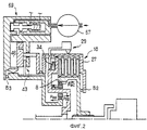
фиг. 1 изображает схематический вид половины продольного разреза предлагаемого механизма трансмиссии, имеющего две передачи, в состоянии покоя;
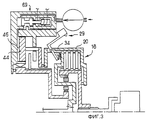
фиг. 2 и 3 изображают виды, аналогичные виду на фиг. 1, но относящиеся соответственно к работе с понижением скорости и работе с прямой передачей;
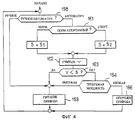
фиг. 4 изображает графическое представление алгоритма управления механизмом трансмиссии, показанным на фиг. 1-3; и
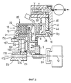
фиг. 5 изображает вид, аналогичный виду на фиг. 3, но соответствующий второму варианту выполнения.In the attached drawings:
FIG. 1 is a schematic view of half a longitudinal section of a proposed transmission mechanism having two gears at rest;
FIG. 2 and 3 are views similar to those in FIG. 1, but relating, respectively, to operation with a reduction in speed and operation with direct transmission;
FIG. 4 is a graphical representation of a transmission mechanism control algorithm shown in FIG. 1-3; and
FIG. 5 is a view similar to that of FIG. 3, but corresponding to the second embodiment.
Механизм трансмиссии с двумя передачами, показанный на фиг. 1 и предназначенный, в частности, для автомобиля, содержит входной вал 2a и выходной вал 2b, расположенные на оси 12 механизма. Вал 2a соединен с выходным валом двигателя 5 автомобиля посредством промежуточной муфты 86. Вал 2b предназначен для прямого или непрямого привода входа дифференциала для приведения в движение ведущих колес транспортного средства. Между валом 2b и входом дифференциала возможна установка, например, другого механизма трансмиссии с двумя или более передачами и/или механизма изменения направления движения вперед или назад с ручным управлением. The dual gear transmission mechanism shown in FIG. 1 and intended, in particular, for an automobile, comprises an
Валы 2a и 2b зафиксированы в осевом направлении по отношению к корпусу 4 механизма трансмиссии. The
Механизм трансмиссии содержит дифференциал, образованный эпициклической передачей 7. Передача 7 содержит коронное колесо 8 с внутренними зубьями и солнечное колесо 9 с внешними зубьями, причем колеса 8 и 9 находятся в зацеплении с планетарными колесами 11, поддерживаемыми с равными угловыми интервалами вокруг оси 12 планетарным водилом 13, которое жестко соединено с выходным валом 2b. Колеса 11 установлены с возможностью свободного вращения вокруг эксцентричных осей 14 водила 13. Колесо 9 установлено с возможностью свободного вращения вокруг оси 12 относительно вала 2b, который оно охватывает. Однако муфта 16 свободного хода предотвращает вращение колеса 9 в обратном направлении, то есть в направлении, противоположном вращению вала 2a по отношению к корпусу 4. The transmission mechanism contains a differential formed by an epicyclic gear 7. The transmission 7 contains a
Колесо 8 заблокировано от проворота, но установлено с возможностью свободного осевого скольжения по отношению к входному валу 2a посредством шлицев 17. The
Вокруг колеса 8 расположена муфта 18, которая содержит пакет кольцевых дисков 19, чередующихся с кольцевыми дисками 22. Диски 19 заблокированы от проворота по отношению к колесу 8 с возможностью осевого скольжения. С этой целью диски 19 снабжены внутренними зубьями, находящимися в зацеплении со шлицами 21, которые выполнены заодно с колесом 8. Диски 22 заблокированы от проворота по отношению к водилу 13 с возможностью осевого перемещения. Для этого кожух 20 на своей внутренней радиальной поверхности содержит шлицы 23, находящиеся в зацеплении с возможностью скольжения как с внешними зубьями дисков 22, так и с внешними зубьями 24 водила 13. Around the
Пакет дисков 19 и 22 может быть зажат в осевом направлении между опорной пластиной 26, выполненной за одно целое с водилом 13, и подвижной пластиной 27, которая является частью кожуха 20. The package of
На кожухе 20 установлены центробежные грузики 29, расположенные кольцом вокруг муфты 18. On the
Грузики, таким образом, заблокированы от проворота по отношению к валу 2b механизма трансмиссии. The weights are thus locked against rotation in relation to the
Каждый грузик имеет массивную основную часть 31, расположенную радиально снаружи дисков 19 и 22, и приводной рычаг 32, прижатый к внешней поверхности пластины 26 посредством тарельчатой пружины 34. Рычаг 32 соединен с частью 31 изогнутым под прямым углом рычагом 33, шарнирно установленным на кожухе 20 на оси 28, расположенной тангенциально по отношению к оси 12. В международной публикации WO-A-91/13275 описаны устройства для шарнирной установки таких грузиков, имеющие ряд преимуществ. Центр G тяжести центробежных грузиков расположен внутри или вблизи части 31 на определенном расстоянии от оси 28, замеренном параллельно оси 12. Each sinker has a massive main part 31, located radially outside the
Таким образом, вращение водила 13 вызывает поворот частей 31 грузиков 29 радиально наружу вокруг их тангенциальных осей 28 под действием центробежных сил Fa с целью их перемещения из положения покоя на кожухе 20, ограниченного стопором 36, в разведенное положение, показанное на фиг. 3. Thus, the rotation of the
В результате этого происходит относительное осевое смещение рычага 32 по отношению к оси 28 шарнира центробежного грузика и, следовательно, рычаг 32 по отношению к кожуху 20. Что касается направления смещения, соответствующего разведению грузиков 29 под действием центробежных сил, то кожух 20 прижимается в осевом направлении к коронному колесу с возможностью свободного относительного вращения посредством упорного подшипника B2.As a result of this, the relative axial displacement of the lever 32 with respect to the axis 28 of the centrifugal sinker hinge and, therefore, the lever 32 with respect to the
Следовательно, смещение кожуха 20 по отношению к рычагу 32 вызывает относительное перемещение последнего и пластины 27 муфты 18b навстречу друг другу. Это относительное смещение может соответствовать сжатию пружины 34 и/или смещению пластины 27 в сторону пластины 26 в направлении включения муфты 18. Therefore, the displacement of the
Когда механизм трансмиссии находится в состоянии покоя, как показано на фиг. 1, пружина 34 посредством грузиков 29, опирающихся в состоянии покоя на кожух 20, передает на последний силу, которая включает муфту 18, так что вал 2a механизма трансмиссии соединяется с валом 2b с возможностью вращения, и механизм трансмиссии образует прямую передачу, обеспечивающую передачу крутящего момента до определенного максимального его значения, ограниченного силой контакта тарельчатой пружины. When the transmission mechanism is at rest, as shown in FIG. 1, the
Кроме того, зубья колес 8, 11 и 9 выполнены винтовыми. Поэтому в каждой паре зубьев, находящихся в зацеплении под нагрузкой, возникают противоположные осевые силы, пропорциональные окружным передаваемым силам и, следовательно, крутящим моментам на валах 2a и 2b. Направление наклона винтовых зубьев выбирают так, что осевые силы Pac (фиг. 2), возникающие в колесе 8 при передаче им приводного крутящего момента, действуют в направлении, в котором колесо 8 толкает пластину 27 посредством подшипника B2. Таким образом, при наличии осевой силы Pac, колесо 8 толкает пластину 27 в направлении отделения ее от пластины 26 муфты 18. На колеса 11, находящиеся в зацеплении не только с колесом 8, но и с колесом 9, воздействуют две противоположные уравновешенные осевые реакционные силы PS1 и PS2, а на колесо 9 из-за его зацепления с колесами 11 воздействует осевая сила Pap, равная по величине и противоположная по направлению осевой силе Pac колеса 8. Сила Pap, вызванная колесом 9, передается на корпус 4 посредством упорного подшипника B3. Таким образом, осевая сила Pac действует на пластину 27 муфты относительно корпуса 4 и, следовательно, относительно пластины 26 муфты и в направлении освобождения муфты 18b. Сила, передаваемая подшипником B2 на кожух 20, также вызывает перемещение рычагов 32, грузиков 29 и пластины 26 навстречу друг другу и, следовательно, сохранение грузиков 29 в положении покоя и сжатие пружины 34.In addition, the teeth of the
Это состояние показано на фиг. 2. Ниже описывается основное функционирование механизма трансмиссии, исходя из того, что он начально находится в этом состоянии. Пока величина крутящего момента, передаваемого блоку валом 2a, такова, что величина осевой силы Pac на колесе 8 достаточна для сжатия пружин 34 и удержания грузиков 29 в положении покоя, показанном на фиг. 2, расстояние между пластинами 26 и 27 муфты позволяет дискам 19 и 22 скользить один по другому без передачи друг другу крутящего момента. В этом случае возможны вращение водила 13 со скоростью, отличной от скорости вала 2a, а также тенденция к его остановке под действием нагрузки, которую должен передать вал 2b. В результате этого колеса 11 стремятся действовать как реверсивный механизм, то есть вращают колесо 9 в направлении, противоположном направлению вращения колеса 8. Но это вращение предотвращается муфтой 16. Следовательно, вращение колеса 9 останавливается муфтой 16, а водило 13 вращается со скоростью, средней между нулевой скоростью колеса 9 и скоростью колеса 8 и вала 2a. Следовательно, блок работает как понижающая передача. Если скорость вращения повышается, а крутящий момент остается неизменным, наступает момент, когда центробежная сила грузиков 29 вызывает между пластинами 26 и 27 осевую силу зацепления, большую по величине осевой силы Pac, и пластина 27 под ее воздействием передвигается в сторону пластины 26 для обеспечения прямой передачи.This state is shown in FIG. 2. The basic operation of the transmission mechanism is described below, based on the fact that it is initially in this state. So far, the amount of torque transmitted to the block by the
Когда муфта 18 включена, вся мощность передается непосредственно от колеса 8, сблокированному с валом 2a, к водилу 13, сблокированному с валом 2b. В результате зубья передачи 7 уже не работают, то есть они уже не передают какой-либо силы и, следовательно, не вызывают какой-либо осевой силы. Таким образом, осевая сила, обусловленная центробежной силой, может быть полностью направлена на сближение пластин 26 и 27 друг с другом. Поэтому становится более понятным процесс переключения на прямую передачу: как только диски 19 и 22 начинают тереться друг о друга и передавать часть мощности, нагрузка на зубья пропорционально уменьшается, осевая сила Pac также пропорционально уменьшается, а преобладание центробежной силы растет до тех пор, пока муфта 18 полностью не обеспечит прямую передачу.When the clutch 18 is turned on, all power is transmitted directly from the
Может оказаться, что скорость вращения вала 2b уменьшается, и/или что передаваемый крутящий момент повышается до величины, при которой грузики 29 не обеспечивают больше в муфте 18 силы сцепления, достаточной для передачи крутящего момента. В этом случае муфта 18 начинает проскальзывать. Скорость колеса 9 уменьшается до нуля. Муфта 16 останавливает солнечное колесо, и снова появляется сила Pac, которая выключает муфту, так что механизм трансмиссии затем работает как понижающая передача. Таким образом, всякий раз, когда происходит переключение с работы с понижением скорости на работу с прямой передачей, осевая сила Pac изменяется, то есть происходит стабилизация нового преобладающего передаточного числа. Большим преимуществом такой конструкции является, с одной стороны, предотвращение слишком частого изменения передач вблизи некоторой критической точки работы и, с другой стороны, кратковременность состояния проскальзывания муфты 18.It may turn out that the rotation speed of the
Когда трансмиссия находится в состоянии покоя, благодаря включению муфты пружины 34 образуют механическое соединение между входом и выходом механизма трансмиссии. Таким образом, транспортное средство удерживается двигателем в неподвижном состоянии, когда последний сам находится в режиме остановки. Если отключить муфту 18 в состоянии покоя трансмиссии, то ничто не препятствует свободному движению транспортного средства на передней передаче, так как в этом случае остановка колеса 8 двигателем 5 вызывает вращение колеса 9 в нормальном направлении, которое муфта 16 не предотвращает. When the transmission is at rest, by engaging the clutch, the
Ниже со ссылкой на фиг. 1 описаны дополнительные средства, предусмотренные для обеспечения избирательного осуществления работы механизма трансмиссии с понижением скорости при условиях, отличных от условий, обусловленных осевыми силами пружин 34, грузиков 29 и зубьев колеса 8. Below with reference to FIG. 1, additional tools are described that are provided for selective operation of the transmission mechanism with a decrease in speed under conditions different from the conditions caused by the axial forces of the
Для этого механизм трансмиссии содержит тормоз 43, который обеспечивает возможность остановки колеса 9 по отношению к корпусу 4 независимо от муфты 16. Другими словами тормоз 43 установлен для работы параллельно с муфтой 16 между колесом 9 и корпусом 4. Гидравлический поршень 44 установлен с возможностью скольжения в осевом направлении выборочно в направлении взаимодействия или разъединения с тормозом 43. Тормоз 43 и поршень 44 имеют кольцевую форму, и их оси совпадают с осью 12 механизма трансмиссии. Поршень 44 расположен смежно с гидравлической камерой 46, в которую может выборочно подаваться масло под давлением для отжатия поршня 44 в направлении взаимодействия с тормозом 43. To this end, the transmission mechanism comprises a
Кроме того, поршень 44 жестко присоединен к толкателю 47, который может упираться в кожух 20 посредством упорного подшипника B4. Когда давление в камере 46 толкает поршень 44 в направлении положения взаимодействия с тормозом 43, кожух 20, прежде чем тормоз 43 включится, отталкивается назад на величину, достаточную для отсоединения муфты 18.In addition, the
Таким образом, когда поршень 44 находится в положении взаимодействия с тормозом (фиг. 2), колесо 9 останавливается, даже если скорость вращения водила 13 превышает скорость вращения колеса 8, что происходит в случае процесса притормаживания, и в результате этого блок обеспечивает работу с понижением скорости, как и при разъединении муфты 18. Thus, when the
Следовательно, узел из элементов 43, 44, 46, 47, описанный выше, образует средства, обеспечивающие водителю транспортного средства возможность работы блока в качестве понижающей передачи, когда водитель желает повысить тормозной эффект двигателя, например на спуске, или приводной крутящий момент на валу 2b. Когда крутящий момент является приводным, тормоз 43 во включенном состоянии оказывает избыточное воздействие вместе с воздействием муфты 16, однако это не является недостатком. Therefore, the assembly of the
Наполнение и опорожнение камеры 46 регулируется электрическим клапаном 69, который в состоянии покоя (фиг. 1 и 3) соединяет камеру 46 с каналом 151 стока, обладающим гидравлическим сопротивлением. При подаче электропитания (фиг. 2) на клапан 69 последний отделяет камеру 46 от канала 151 и соединяет ее с выходом насоса 57, приводимого в действие двигателем 5. Независимо от состояния клапана 69, насос 57 может также использоваться для питания контура смазки (не показан) механизма трансмиссии. The filling and emptying of the
Клапан 69 управляется блоком 152 управления, соединенным с датчиком 153, определяющим скорость транспортного средства (или скорость вала 2b), с датчиком положения переключателя 154, устанавливающего ручное или автоматическое управление и выполненного доступным для водителя, с датчиком положения педали 156 акселератора и с переключателем 157, устанавливающим нормальный или спортивный режим транспортного средства и обеспечивающим водителю возможность выбора между двумя различными автоматическими режимами работы механизма трансмиссии. The
Из вышесказанного очевидно, что пружины 34 устанавливают механизм трансмиссии на прямую передачу, когда транспортное средство неподвижно. Следовательно, при трогании с места для появления на зубьях силы Pac необходимо переключить механизм трансмиссии на работу с понижением скорости, так чтобы затем завершение этого режима проводилось на низшей передаче. Это может систематически вызывать нежелательный удар, для предотвращения которого предусмотрено, что узел, содержащий тормоз 43, поршень 44 и толкатель 47, устанавливает механизм трансмиссии в положение работы с понижением скорости, когда работает двигатель (работает насос 57), но когда скорость вала 2b, определяемая датчиком 153, ниже определенного порога S, величина которого поясняется ниже. Таким образом, когда начинается движение вала 2b, механизм трансмиссии уже осуществляет работу с понижением скорости, и так до тех пор, пока скорость выходного вала не превысит порога S.From the foregoing, it is obvious that the
Переключатель 157 обеспечивает водителю возможность изменять порог S. Если водитель выбирает нормальный режим, порог S достаточно низок и соответствует, например, скорости двигателя 5, составляющей 2500 об/мин при работе механизма трансмиссии с понижением скорости. The switch 157 provides the driver with the ability to change the threshold S. If the driver selects the normal mode, the threshold S is low enough and corresponds, for example, to the
Как только происходит превышение порога, клапан 69 устанавливает привод 44, 46 в положение слива, при этом обеспечивается возможность переключения механизма трансмиссии на работу с прямой передачей, если величина осевой силы, создаваемой центробежными грузиками или пружиной 34, достаточна для преодоления силы Рас на зубьях, направленной в противоположном направлении. Если водитель выбирает спортивный режим, порог S - высокий и соответствует, например, скорости двигателя 5, составляющей 3500 об/мин при работе механизма трансмиссии с понижением скорости.As soon as the threshold is exceeded, the
После превышения порога S камера 46 не опорожняется, пока механизм трансмиссии работает с понижением скорости, потому что ничто не толкает обратно поршень 44. Когда сила центробежных грузиков начинает преодолевать силу на зубьях, первые поднимаются и перемещают кожух 20 в направлении выталкивания поршня 44 назад посредством упорного подшипника B4. При этом камера 46 опорожняется через канал 151, и в результате создается тормозная или демпфирующая сила на поршне, которая передается на кожух 20. Следовательно, центробежными грузиками предотвращается внезапное включение муфты 18.After exceeding the threshold S, the
Когда датчик 156 определяет, что педаль акселератора полностью отжата вниз, блок 152 приводит в действие клапан 69, при этом камера 46 заполняется, и в результате начинается работа с понижением скорости. When the sensor 156 determines that the accelerator pedal is fully depressed, the block 152 actuates the
Переключатель 154 обеспечивает водителю возможность выбора между автоматической работой, описанной выше, и работой с понижением скорости. В последнем случае блок 152 обеспечивает постоянное наполнение камеры 46. Switch 154 provides the driver with a choice between automatic operation described above and speed reduction operation. In the latter case, the block 152 provides a constant filling of the
На фиг. 4 показано графическое представление алгоритма работы блока 152. Тест 158 определяет состояние переключателя 154. Если переключатель 154 находится в положении "ручное управление", непосредственно выдается команда 159 на наполнение привода 44, 46. Если переключатель 154 находится в положении "автоматическое управление", тест 161 определяет состояние переключателя 157 и в зависимости от результата этой проверки присваивает порогу значение S1 или S2. Наконец, посредством датчика 153 считывается скорость V транспортного средства (шаг 162), которая затем в тесте 163 сравнивается с порогом S. Если скорость V меньше порога S, выдается команда 159 на наполнение привода. В противном случае тест 164 выдает команду на опорожнение привода (команда 166) до тех пор, пока датчик 156 не укажет на требование высокой мощности, поступившее от водителя, в этом случае выдается команда 159 на наполнение привода. In FIG. 4 shows a graphical representation of the operation algorithm of block 152.
Таким образом, когда механизм трансмиссии переключается с работы с понижением скорости на работу с прямой передачей, будь то после трогания с места или при разгоне с низкой скорости, или когда водитель отпускает педаль акселератора после ее сильного нажатия, или когда он перемещает переключатель 154 из положения "ручное управление" в положение "автоматическое управление", или же переключатель 157 из положения "спортивный режим" в положение "нормальный режим", фактически во всех этих случаях камера 46 заполняется гидравлической жидкостью и, следовательно, должна опорожняться с обеспечением уже описанного тормозного эффекта и возможности включения муфты 18 посредством пластины 27. Это дает особое преимущество, когда сила поршня 44 является определяющим фактором в поддержании работы в качестве понижающей передачи: действительно, в этом случае внезапное исчезновение силы поршня 44 создает риск внезапного включения муфты 18. Амортизация удара, обусловленная затрудненным опорожнением камеры 46, предотвращает внезапное включение муфты абсолютно во всех этих случаях. Thus, when the transmission mechanism shifts from low-speed operation to direct-drive operation, whether after starting off or accelerating at low speed, or when the driver releases the accelerator pedal after pressing it hard, or when he moves switch 154 from position "manual control" to the "automatic control" position, or the switch 157 from the "sports mode" to the "normal mode" position, in virtually all of these cases, the
При понижении скорости транспортного средства, даже если водитель отпускает педаль акселератора, механизм трансмиссии переключается на работу с понижением скорости при прохождении порога S в направлении снижения скорости. Водитель может также повысить эффект торможения двигателем путем установки переключателя 154 в положение "ручное управление". When the vehicle speed decreases, even if the driver releases the accelerator pedal, the transmission mechanism switches to lower speed when passing threshold S in the direction of decreasing speed. The driver can also increase the effect of engine braking by setting the switch 154 to the "manual control" position.
Для наполнения камеры 46 для обеспечения описанных выше функций возможно использование гидравлического давления достаточно большой величины, обеспечивающего преодоление осевой силы, создаваемой грузиками 29 и имеющей противоположное направление, при любой скорости вращения маховиков вокруг оси 12. To fill the
Но с точки зрения безопасности и экономии энергии предпочтительно подавать в камеру 46 ограниченное по величине давление, так чтобы осевая сила поршня 44 обеспечивала преодоление противоположной силы грузиков 29, только если скорость вращения центробежных грузиков мала настолько, что переключение на работу с понижением скорости не приводит к слишком высокой скорости двигателя 5. But from the point of view of safety and energy saving, it is preferable to apply a pressure of limited magnitude to the
В положении, показанном на фиг. 1, двигатель и транспортное средство неподвижны, и питание на блок 152 и клапан 69 не подается, и, следовательно, последний находится в положении опорожнения камеры 46. Пружины 34, опирающиеся на пластину 27, толкают кожух 20 в положение включения муфты 18 и опорожнения камеры 46. Механизм трансмиссии находится в положении прямой передачи и потому обеспечивает двигателю 5 возможность действовать в качестве стояночного тормоза. In the position shown in FIG. 1, the engine and the vehicle are stationary and no power is supplied to the block 152 and
Как показано на фиг. 2, камера 46 наполняется и поддерживает работу с понижением скорости с помощью силы Рас на зубьях и против силы грузиков 29 или пружин 34 (конструкция узла позволяет соответственно действовать только большей из двух сил, создаваемых грузиками 29 и пружиной 34). Возможно также, что величина силы на зубьях достаточна для поддержания работы с понижением скорости, когда камера 46 не наполняется, но это состояние не показано. Напротив, когда двигатель вращается, но муфта 86 выключена, сила Pac на зубьях уже отсутствует, и один поршень 44, противодействуя силе пружины 34, удерживает муфту 18 в выключенном состоянии.As shown in FIG. 2, the
Как показано на фиг. 3, камера 46 не наполняется, и грузики 29 отодвигают кожух в положение включения муфты 18 и опорожнения камеры 46, при этом пружины 34 сжаты. As shown in FIG. 3, the
Ниже описаны только отличия механизма трансмиссии, показанного на фиг. 5, от механизма, изображенного на фиг. 1 - 3. Only differences in the transmission mechanism shown in FIG. 5 from the mechanism depicted in FIG. 13.
Использование эпициклической передачи с входом на коронном колесе и выходом на планетарном водиле с трудом обеспечивает возможность достижения передаточных отношений больше 1.6. The use of an epicyclic gear with an input on the crown wheel and an output on a planetary carrier with difficulty makes it possible to achieve a gear ratio greater than 1.6.
В определенных случаях возможна потребность в значительно большем понижении скорости, особенно когда в трансмиссии используются несколько двухскоростных механизмов и где определенные передаточные отношения достигаются путем переключения одного механизма на работу с понижением скорости, в то время как другое переключается на прямую передачу. Следовательно, необходимо, чтобы при работе с понижением скорости один из двух механизмов имел передаточное отношение, приблизительно равное 3. In certain cases, the need for a significantly larger reduction in speed is possible, especially when several two-speed mechanisms are used in the transmission and where certain gear ratios are achieved by switching one mechanism to work with lowering speed, while the other switches to direct transmission. Therefore, it is necessary that when working with a decrease in speed, one of the two mechanisms should have a gear ratio of approximately equal to 3.
С этой целью к валу 2a механизма трансмиссии присоединено с возможностью скольжения колесо 9, которое прижато в осевом направлении к кожуху 20 посредством упорного подшипника B2, так что сила Pac на зубьях предается на кожух 20 в направлении выключения муфты 18.To this end, a
Водило 13 также заблокировано от проворота относительно вала 2b, но в силу ряда практических причин это соединение в данной конструкции не прямое, а выполнено посредством кожуха 20 и осевых шлицов 167, расположенных между кожухом 20 и валом 2b. Следовательно, кожух 20 имеет возможность свободно скользить относительно вала 2b. Предусмотрены не показанные на чертеже средства, которые останавливают вал 2b и водило 13 в осевом направлении относительно кожуха 4. The
Колесо 8 присоединено к корпусу 4 посредством муфты 16 и выборочно посредством тормоза 43. Муфта 16 предотвращает вращение колеса 8 в обратном направлении. Кроме того, колесо 8 передает создаваемую им осевую силу Pac зубьев на корпус 4 посредством упорного подшипника B3.The
Диски 19 муфты 18 находятся в зацеплении со шлицами 21, которые выполнены заодно с колесом 9. The
Кроме того, и вал 2b, и кожух 20 имеют фланцы 168, 169, ограничивающие расположенную между ними амортизирующую кольцевую камеру 171, соединенную каналом 172, обладающим гидравлическим сопротивлением, с каналом 173 для подачи смазки, выполненным в центре выходного вала 2b. In addition, both the
Полностью не показано, что такой смазочный канал, подача смазки в который осуществляется насосом 59, может быть выполнен вдоль всей длины оси 12 трансмиссии для смазки подшипников, шлицев, упорных подшипников, манжет и т. д. За исключением канала 172, камера 171 герметична, в частности благодаря двум уплотнениям 174, установленным в кожухе 20 с возможностью скольжения по цилиндрическим опорным поверхностям вала 2b при относительном взаимном перемещении кожуха 20 и вала 2b. Шлицы 167 находятся в камере 171. Конструкция узла обеспечивает возможность уменьшения объема камеры 171 при перемещении кожух 20 в направлении выключения муфты 18, для которого, следовательно, необходимо опорожнение камеры 171 через узкий канал 172. It is not completely shown that such a lubricating channel, the supply of lubricant to which is carried out by the pump 59, can be performed along the entire length of the
Таким образом, в примере, показанном на фиг. 5, необходимость опорожнения камеры 46 предотвращает не только внезапное включение муфты 18, но также ее внезапное выключение, которое может внезапно привести в действие муфту 16 и которое предотвращается необходимостью опорожнения камеры 171. Это особенно целесообразно в примере, показанном на фиг. 5, где скорость вращения изменяется в 3 раза при включенной и выключенной муфте. Когда муфта включается, камера 171 опять втягивает масло через канал 172. Thus, in the example shown in FIG. 5, the need to empty the
Кроме этого, функционирование механизма, показанного на фиг. 5, аналогично показанному на фиг. 1 - 4, за исключением того, что при прямой передаче муфта 18 соединяет уже колесо 9, а не колесо 8, с валом 2b, и того, что при работе с понижением скорости остановлено колесо 8, что обеспечивает между колесом 9 и водилом 13 передаточное число, равное примерно 3, вместо 1.5, имеющееся между колесом 8 и водилом 13 в примере, показанном на фиг. 1 - 3. In addition, the operation of the mechanism shown in FIG. 5, similar to that shown in FIG. 1 to 4, with the exception that in direct transmission, the clutch 18 already connects the
Разумеется, изобретение не ограничивается описанными и показанными на чертежах вариантами выполнения. Of course, the invention is not limited to the embodiments described and shown in the drawings.
Когда водителю требуется спортивный режим вождения, способствующий увеличению скорости вращения вала 2a, существует возможность подведения постоянного давления к камере 46 для создания на кожухе 20 силы, вычитающейся из силы зацепления, вызванной центробежными грузиками. Таким образом, передаваемый крутящий момент при прямой передаче для заданной скорости вращения центробежных грузиков имеет меньшую величину, а скорость, при превышении которой трансмиссия возвращается от работы с понижением скорости к прямой передаче для данного крутящего момента, имеет большее значение. When a driver needs a sporty driving mode that helps increase the speed of rotation of the
Возможно осуществление управления посредством гидравлического блока управления, а не электронного. It is possible to control via a hydraulic control unit, and not electronic.
Описанные механизмы трансмиссии, имеющие две передачи, могут быть скомбинированы для образования более сложных трансмиссий, таких, как, например, описаны в международной публикации WO-A-9207206. Возможно также применение изобретения в трансмиссиях, имеющих несколько передач, в частности таких, как описаны в той же публикации WO-A-9207206. The described transmission mechanisms having two gears can be combined to form more complex transmissions, such as, for example, described in international publication WO-A-9207206. It is also possible to use the invention in transmissions having several gears, in particular those described in the same publication WO-A-9207206.
Основная конструкция, содержащая передачу 7, изображенную на фиг. 1 или фиг. 5, и обеспечивающая возможность работы на прямой передаче посредством муфты, приводимой в действие центробежной силой, и работы с понижением скорости под действием привода, выключающего муфту против воздействия центробежных грузиков, имеет преимущество, заключающееся в том, что сила привода повышается пропорционально скорости вращения центробежных грузиков. Когда привод выполнен в виде гидравлического привода 44, 46, такой же эффект может быть достигнут при использовании насоса 57, создающего давление, повышающееся пропорционально скорости вала 2b. Таким образом, когда привод приходит в действие для выключения муфты, последнее осуществляется достаточно постепенно, так как сила привода 44, 46 лишь немного превышает силу центробежных грузиков, какой бы ни была скорость вращения. The main structure comprising gear 7 depicted in FIG. 1 or FIG. 5, and providing the possibility of working in direct transmission by means of a clutch driven by centrifugal force, and working with a decrease in speed under the action of a drive that turns off the clutch against the action of centrifugal weights, has the advantage that the drive force increases in proportion to the speed of rotation of centrifugal weights . When the actuator is in the form of a
В более общем смысле эта особенность изобретения обеспечивает вероятность того, что привод, приведенный в действие, создает изменяющуюся силу, превышающую на достаточную величину переменную противодействующую силу, которую он должен преодолеть для изменения состояния муфты. In a more general sense, this feature of the invention provides the likelihood that the drive, driven, creates a changing force that is sufficient by a sufficient amount of the variable counteracting force that it must overcome to change the state of the coupling.
Claims (34)
Applications Claiming Priority (3)
| Application Number | Priority Date | Filing Date | Title |
|---|---|---|---|
| FR94/10109 | 1994-08-18 | ||
| FR9410109A FR2723775A1 (en) | 1994-08-18 | 1994-08-18 | TRANSMISSION DEVICE, PARTICULARLY FOR VEHICLE, AND DRIVING METHOD RELATING THERETO. |
| PCT/FR1995/001091 WO1996006293A1 (en) | 1994-08-18 | 1995-08-17 | Transmission device, in particular, for vehicles and related method for controlling transmission |
Publications (2)
| Publication Number | Publication Date |
|---|---|
| RU97104209A RU97104209A (en) | 1999-03-10 |
| RU2145683C1 true RU2145683C1 (en) | 2000-02-20 |
Family
ID=9466368
Family Applications (1)
| Application Number | Title | Priority Date | Filing Date |
|---|---|---|---|
| RU97104209/28A RU2145683C1 (en) | 1994-08-18 | 1995-08-17 | Transmission mechanisms for transport facility and method of control of this mechanism |
Country Status (24)
| Country | Link |
|---|---|
| US (1) | US5885180A (en) |
| EP (1) | EP0775272B1 (en) |
| JP (1) | JPH10504376A (en) |
| KR (1) | KR100349828B1 (en) |
| CN (1) | CN1077257C (en) |
| AT (1) | ATE173328T1 (en) |
| AU (1) | AU709183B2 (en) |
| BR (1) | BR9508616A (en) |
| CA (1) | CA2197228A1 (en) |
| CZ (1) | CZ47397A3 (en) |
| DE (1) | DE69505989T2 (en) |
| DK (1) | DK0775272T3 (en) |
| ES (1) | ES2126921T3 (en) |
| FR (1) | FR2723775A1 (en) |
| HU (1) | HU222661B1 (en) |
| MX (1) | MX9701237A (en) |
| MY (1) | MY114778A (en) |
| PL (1) | PL179176B1 (en) |
| RO (1) | RO117396B1 (en) |
| RU (1) | RU2145683C1 (en) |
| SK (1) | SK280274B6 (en) |
| UA (1) | UA55372C2 (en) |
| WO (1) | WO1996006293A1 (en) |
| ZA (1) | ZA956888B (en) |
Cited By (2)
| Publication number | Priority date | Publication date | Assignee | Title |
|---|---|---|---|---|
| RU2471097C2 (en) * | 2008-08-14 | 2012-12-27 | Халдекс Трэкшн Аб | Hydraulic actuator |
| RU2491460C2 (en) * | 2008-06-18 | 2013-08-27 | СКАНИА СВ АБ (пабл) | Method and system for control of transmission at low power |
Families Citing this family (20)
| Publication number | Priority date | Publication date | Assignee | Title |
|---|---|---|---|---|
| FR2738044B1 (en) * | 1995-08-24 | 1997-11-21 | Antonov Automotive Europ | METHOD FOR CONTROLLING A SHIFT, AND TRANSMISSION DEVICE FOR IMPLEMENTING IT |
| FR2768210B1 (en) * | 1997-09-05 | 1999-11-19 | Antonov Automotive Europ | METHOD FOR ADJUSTING THE PROGRESSIVITY OF A GEAR CHANGE, AND RELATED TRANSMISSION DEVICE |
| JP4026959B2 (en) * | 1998-10-20 | 2007-12-26 | 本田技研工業株式会社 | transmission |
| US6209695B1 (en) * | 1999-08-24 | 2001-04-03 | Borgwarner Inc. | Multi-speed transmission with no lag electronically controlled valving |
| JP2001165250A (en) * | 1999-12-07 | 2001-06-19 | Honda Motor Co Ltd | Vehicular automatic transmission |
| JP2001173683A (en) * | 1999-12-17 | 2001-06-26 | Honda Motor Co Ltd | Centrifugal friction clutch for autoamtic transmission |
| FR2813649B1 (en) | 2000-09-06 | 2002-11-15 | Antonov Automotive Europ | TRANSMISSION DEVICE, PARTICULARLY FOR THE AUTOMOTIVE |
| US6663527B2 (en) | 2001-12-27 | 2003-12-16 | Visteon Global Technologies, Inc. | Planetary gear system for controlling torque transfer in a vehicle driveline |
| FR2840043B1 (en) * | 2002-05-23 | 2004-12-03 | Antonov Automotive Europ | TRANSMISSION DEVICE, FOR LAND VEHICLE, ESPECIALLY CAR |
| US6830529B2 (en) * | 2002-06-14 | 2004-12-14 | Visteon Global Technologies, Inc. | Torque transfer assembly with planetary differential |
| JP4899082B2 (en) * | 2004-06-08 | 2012-03-21 | Smc株式会社 | Automatic reduction ratio switching device |
| FR2875568B1 (en) * | 2004-09-23 | 2008-04-18 | Antonov Automotive Europ | TRANSMISSION DEVICE FOR AUXILIARY OR ACCESSORY OF VARIABLE SPEED MOTOR, ENGINE THUS EQUIPPED AND APPLICATIONS |
| GB2455097B (en) * | 2007-11-27 | 2010-01-06 | Antonov Automotive Europ | Dual pulley transmission unit |
| GB2455708B (en) * | 2007-12-13 | 2010-02-17 | Antonov Automotive Europ | A transmission unit for relaying drive from a crankshaft of an internal combustion engine ancillaries with lubricating oil retained in casing |
| WO2011042951A1 (en) * | 2009-10-05 | 2011-04-14 | トヨタ自動車株式会社 | Control device for vehicle drive device |
| CN101799060A (en) * | 2010-03-08 | 2010-08-11 | 张家港金凯达机械有限公司 | Gear transmission device |
| KR101282697B1 (en) * | 2011-05-19 | 2013-07-05 | 현대자동차주식회사 | Apparatus for reducing transmission shock of automatic transmission |
| BR112014006705B1 (en) * | 2011-09-23 | 2021-05-11 | Chrysler Group Llc | apparatus and method for engaging a friction element in a transmission of a vehicle |
| KR102399477B1 (en) * | 2017-07-28 | 2022-05-18 | 현대자동차주식회사 | Apparatus for auto shifting of vehicle |
| CN117489757B (en) * | 2024-01-03 | 2024-03-22 | 常州市曼多林精密机械科技股份有限公司 | Anti-loosening structure of planetary reducer |
Family Cites Families (13)
| Publication number | Priority date | Publication date | Assignee | Title |
|---|---|---|---|---|
| JPS6081552A (en) * | 1983-10-07 | 1985-05-09 | Nissan Motor Co Ltd | Hydraulic controlling device of automatic transmission |
| JPS6213849A (en) * | 1985-07-08 | 1987-01-22 | Daikin Mfg Co Ltd | Control mechanism for speed change shift in automatic transmission |
| FR2668231B1 (en) * | 1990-10-18 | 1995-12-08 | Roumen Antonov | TRANSMISSION DEVICE, ESPECIALLY FOR A MOTOR VEHICLE. |
| US5514044A (en) * | 1990-01-18 | 1996-05-07 | Antonov Automotive North America B.V. | In-series automatic transmission modules directly responsive to torque |
| US5263906A (en) * | 1990-08-30 | 1993-11-23 | Antonov Automotive North America B.V. | Mechanical automatic transmission directly responsive to torque |
| FR2662483A2 (en) * | 1990-02-28 | 1991-11-29 | Antonov Roumen | VARIABLE RATIO TRANSMISSION DEVICE PARTICULARLY FOR THE AUTOMOBILE. |
| US5409428A (en) * | 1990-02-28 | 1995-04-25 | Antonov Automotive North America B.V. | Centrifugal clutch in a planetary transmission device |
| US5106348A (en) * | 1991-05-08 | 1992-04-21 | Koivunen Erkki A | Bi-directional multi-mode clutch for change-speed transmission unit for automatic change speed transmissions |
| FR2682646B1 (en) * | 1991-10-18 | 1994-01-14 | Roumen Antonov | AUTOMATIC CLUTCH CONTROL METHOD AND AUTOMATIC TRANSMISSION DEVICE RELATING THERETO. |
| FR2693247B1 (en) * | 1992-07-03 | 1995-03-10 | Modern Automotive Technologies | Method for controlling a gear change and related gear transmission device, in particular for a vehicle. |
| FR2701746B1 (en) * | 1993-02-18 | 1995-05-19 | Roumen Antonov | Transmission with soft start device, in particular for vehicle. |
| FR2701747B1 (en) * | 1993-02-18 | 1995-04-21 | Roumen Antonov | Transmission device, in particular for a vehicle, and control methods relating thereto. |
| FR2708065B1 (en) * | 1993-07-23 | 1995-09-22 | Antonov Automotive Europ | Volumetric coupling device and transmission device thus equipped. |
-
1994
- 1994-08-18 FR FR9410109A patent/FR2723775A1/en active Granted
-
1995
- 1995-08-17 SK SK156-97A patent/SK280274B6/en unknown
- 1995-08-17 RO RO97-00309A patent/RO117396B1/en unknown
- 1995-08-17 DK DK95927792T patent/DK0775272T3/en active
- 1995-08-17 US US08/793,063 patent/US5885180A/en not_active Expired - Fee Related
- 1995-08-17 AU AU31803/95A patent/AU709183B2/en not_active Ceased
- 1995-08-17 CN CN95195688A patent/CN1077257C/en not_active Expired - Fee Related
- 1995-08-17 RU RU97104209/28A patent/RU2145683C1/en not_active IP Right Cessation
- 1995-08-17 CA CA002197228A patent/CA2197228A1/en not_active Abandoned
- 1995-08-17 CZ CZ97473A patent/CZ47397A3/en unknown
- 1995-08-17 EP EP95927792A patent/EP0775272B1/en not_active Expired - Lifetime
- 1995-08-17 MX MX9701237A patent/MX9701237A/en unknown
- 1995-08-17 JP JP8507822A patent/JPH10504376A/en not_active Ceased
- 1995-08-17 KR KR1019970701025A patent/KR100349828B1/en not_active IP Right Cessation
- 1995-08-17 PL PL95318694A patent/PL179176B1/en not_active IP Right Cessation
- 1995-08-17 WO PCT/FR1995/001091 patent/WO1996006293A1/en not_active Application Discontinuation
- 1995-08-17 HU HU9701768A patent/HU222661B1/en not_active IP Right Cessation
- 1995-08-17 BR BR9508616A patent/BR9508616A/en not_active IP Right Cessation
- 1995-08-17 DE DE69505989T patent/DE69505989T2/en not_active Expired - Fee Related
- 1995-08-17 AT AT95927792T patent/ATE173328T1/en not_active IP Right Cessation
- 1995-08-17 ES ES95927792T patent/ES2126921T3/en not_active Expired - Lifetime
- 1995-08-17 ZA ZA956888A patent/ZA956888B/en unknown
- 1995-08-17 UA UA97030969A patent/UA55372C2/en unknown
- 1995-08-18 MY MYPI95002421A patent/MY114778A/en unknown
Cited By (2)
| Publication number | Priority date | Publication date | Assignee | Title |
|---|---|---|---|---|
| RU2491460C2 (en) * | 2008-06-18 | 2013-08-27 | СКАНИА СВ АБ (пабл) | Method and system for control of transmission at low power |
| RU2471097C2 (en) * | 2008-08-14 | 2012-12-27 | Халдекс Трэкшн Аб | Hydraulic actuator |
Also Published As
| Publication number | Publication date |
|---|---|
| ATE173328T1 (en) | 1998-11-15 |
| WO1996006293A1 (en) | 1996-02-29 |
| AU3180395A (en) | 1996-03-14 |
| DE69505989T2 (en) | 1999-06-10 |
| DE69505989D1 (en) | 1998-12-17 |
| EP0775272A1 (en) | 1997-05-28 |
| KR100349828B1 (en) | 2002-11-23 |
| ZA956888B (en) | 1996-03-13 |
| BR9508616A (en) | 1997-09-30 |
| FR2723775B1 (en) | 1997-03-07 |
| MY114778A (en) | 2003-01-31 |
| PL318694A1 (en) | 1997-07-07 |
| US5885180A (en) | 1999-03-23 |
| UA55372C2 (en) | 2003-04-15 |
| FR2723775A1 (en) | 1996-02-23 |
| CA2197228A1 (en) | 1996-02-29 |
| AU709183B2 (en) | 1999-08-26 |
| SK280274B6 (en) | 1999-10-08 |
| HU222661B1 (en) | 2003-09-29 |
| EP0775272B1 (en) | 1998-11-11 |
| CN1077257C (en) | 2002-01-02 |
| DK0775272T3 (en) | 1999-07-26 |
| JPH10504376A (en) | 1998-04-28 |
| MX9701237A (en) | 1997-05-31 |
| RO117396B1 (en) | 2002-02-28 |
| CN1160437A (en) | 1997-09-24 |
| HUT76964A (en) | 1998-01-28 |
| CZ47397A3 (en) | 1998-05-13 |
| PL179176B1 (en) | 2000-07-31 |
| ES2126921T3 (en) | 1999-04-01 |
| SK15697A3 (en) | 1997-11-05 |
Similar Documents
| Publication | Publication Date | Title |
|---|---|---|
| RU2145683C1 (en) | Transmission mechanisms for transport facility and method of control of this mechanism | |
| RU2114345C1 (en) | Transmission device | |
| KR100196309B1 (en) | Variable speed transmission device, particularly for motor vehicles | |
| RU97104209A (en) | TRANSMISSION MECHANISM, ESPECIALLY FOR VEHICLES AND METHOD FOR MANAGING THIS MECHANISM | |
| EA000123B1 (en) | Multiple-disc coupling device automatic transmission provided therewith and method for making same | |
| JPH07217709A (en) | Gear shifter | |
| JP3585923B2 (en) | Vehicle transmission device and control method therefor | |
| RU2133896C1 (en) | Transmission with gentle start device for car in particular | |
| KR19990044080A (en) | How to perform shifting and shifting device for performing the same | |
| RU2127380C1 (en) | Method of control of change of gear ratio and gear transmission used for realization of this method | |
| CN100394070C (en) | Transmission device for land vehicle, such as a cart | |
| UA45498C2 (en) | METHOD OF ESTABLISHING SMOOTH TRANSMISSION OF TRANSMISSION MECHANISM AND TRANSMISSION DEVICE RELATED TO THIS | |
| US5993346A (en) | Transmission device particularly for vehicles, and controlled methods associated therewith | |
| GB2221964A (en) | Automatic variable speed gear comprising planetary gearing and speed responsive coupling | |
| JPS60201152A (en) | Automatic speed change gear for car | |
| JPS59219547A (en) | Automatic speed change gear for electric automobile | |
| FR2676792A3 (en) | Automatic gear box |
Legal Events
| Date | Code | Title | Description |
|---|---|---|---|
| MM4A | The patent is invalid due to non-payment of fees |
Effective date: 20050818 |