RU2138362C1 - Method and apparatus for cooling rolls of continuous metal strip of ribbon casting mill - Google Patents
Method and apparatus for cooling rolls of continuous metal strip of ribbon casting mill Download PDFInfo
- Publication number
- RU2138362C1 RU2138362C1 RU95113729/02A RU95113729A RU2138362C1 RU 2138362 C1 RU2138362 C1 RU 2138362C1 RU 95113729/02 A RU95113729/02 A RU 95113729/02A RU 95113729 A RU95113729 A RU 95113729A RU 2138362 C1 RU2138362 C1 RU 2138362C1
- Authority
- RU
- Russia
- Prior art keywords
- cooling
- roll
- fluid
- rolls
- circuit
- Prior art date
Links
Images
Classifications
-
- B—PERFORMING OPERATIONS; TRANSPORTING
- B22—CASTING; POWDER METALLURGY
- B22D—CASTING OF METALS; CASTING OF OTHER SUBSTANCES BY THE SAME PROCESSES OR DEVICES
- B22D11/00—Continuous casting of metals, i.e. casting in indefinite lengths
- B22D11/12—Accessories for subsequent treating or working cast stock in situ
-
- B—PERFORMING OPERATIONS; TRANSPORTING
- B22—CASTING; POWDER METALLURGY
- B22D—CASTING OF METALS; CASTING OF OTHER SUBSTANCES BY THE SAME PROCESSES OR DEVICES
- B22D11/00—Continuous casting of metals, i.e. casting in indefinite lengths
- B22D11/06—Continuous casting of metals, i.e. casting in indefinite lengths into moulds with travelling walls, e.g. with rolls, plates, belts, caterpillars
- B22D11/0637—Accessories therefor
- B22D11/068—Accessories therefor for cooling the cast product during its passage through the mould surfaces
- B22D11/0682—Accessories therefor for cooling the cast product during its passage through the mould surfaces by cooling the casting wheel
-
- B—PERFORMING OPERATIONS; TRANSPORTING
- B21—MECHANICAL METAL-WORKING WITHOUT ESSENTIALLY REMOVING MATERIAL; PUNCHING METAL
- B21B—ROLLING OF METAL
- B21B27/00—Rolls, roll alloys or roll fabrication; Lubricating, cooling or heating rolls while in use
- B21B27/06—Lubricating, cooling or heating rolls
- B21B27/08—Lubricating, cooling or heating rolls internally
Abstract
Description
Изобретение касается способа и устройства для охлаждения валков для непрерывного литья металлической полосы, обеспечивающего коррекцию овализации при нарушении округлости термического или теплового происхождения, проявляющейся на валках установок непрерывного литья металлической полосы или ленты, имеющих два валка одинаковой формы, вращающихся в противоположных направлениях и принудительно охлаждаемых изнутри. The invention relates to a method and device for cooling rolls for continuous casting of a metal strip, providing ovalization correction in case of roundness of thermal or thermal origin, manifested on rolls of continuous casting of a metal strip or tape having two rolls of the same shape, rotating in opposite directions and forcibly cooled from the inside .
Установка для непрерывного литья тонкой металлической полосы или ленты содержит обычно два одинаковых валка, располагающихся друг против друга и разделенных между собой некоторым пространством, ширина которого соответствует требуемой толщине отливаемой на данной установке металлической полосы или ленты, причем упомянутые валки приводятся во вращательное движение в противоположных направлениях. An apparatus for continuous casting of a thin metal strip or tape usually contains two identical rolls, located opposite each other and separated by a certain space, the width of which corresponds to the required thickness of the metal strip or tape cast on this installation, and the said rolls are rotated in opposite directions .
Расплавленный металл в жидком состоянии подается с одной из сторон упомянутого выше пространства, с другой стороны которого выходит затвердевшая полоса или лента кристаллизовавшегося металла номинальной толщины. The molten metal in a liquid state is supplied from one side of the space mentioned above, on the other side of which there is a hardened strip or crystallized metal strip of nominal thickness.
При использовании такой установки можно изготавливать тонкие полосы или ленты из различных металлов толщиной от нескольких сантиметров до единиц миллиметров и менее. Using such an installation, thin strips or tapes can be made of various metals with thicknesses from a few centimeters to units of millimeters or less.
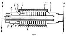
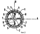
Патент Франции N 2217098 описывает валок установки для непрерывного литья и деталь общей конструкции такого валка приведена ниже на фиг. 1 (продольный разрез) и фиг. 2 (поперечный разрез). French Patent No. 2217098 describes a roll of a continuous casting machine and a detail of the general construction of such a roll is shown below in FIG. 1 (longitudinal section) and FIG. 2 (cross section).
Такой валок содержит цилиндрический корпус 1 (центральная часть), который охвачен бандажом 2, непосредственно контактирующим с расплавленным металлом, причем этот бандаж служит для фактической прокатки изготавливаемой полосы или ленты. Вследствие этого имеется необходимость в принудительном охлаждении всей системы валка такой установки. Such a roll contains a cylindrical body 1 (central part), which is covered by a band 2, which is in direct contact with molten metal, and this band serves for the actual rolling of the manufactured strip or tape. As a consequence, there is a need for forced cooling of the entire roll system of such an installation.
Это принудительное охлаждение обычно осуществляется при помощи циркуляции некоторой охлаждающей жидкости (как правило в качестве этой охлаждающей жидкости используется обычная вода), проходящей через по меньшей мере один охлаждающий контур, располагающийся внутри цилиндрического корпуса данного валка 1. This forced cooling is usually carried out by circulating some cooling liquid (usually ordinary water is used as this cooling liquid) passing through at least one cooling circuit located inside the cylindrical body of this
Этот контур содержит по меньшей мере одно отверстие подвода холодной воды 3, выполненное в виде перфорированной трубки в корпусе валка 1, располагающейся параллельно оси этого валка и открывающейся наружу на одном из своих концов, причем другой конец этой трубки закрыт. Трубка подачи холодной воды проходит в непосредственной близости от бандажа 2 по всей его ширине. This circuit contains at least one
Множество трубок меньшего диаметра 4 связывает каждое отверстие подвода холодной воды 3 с распределительным коллектором 5 типа канавки или желобка, располагающимся под бандажом 2 и строго параллельным подводящей трубке 3. Каждый коллектор питает водой собственно охлаждающее устройство, содержащее систему малых каналов 5, проточенных на периферийной поверхности корпуса валка 1 и располагающихся под бандажом в поперечной плоскости. Там происходит циркуляция воды, которая входит в тепловой контакт с бандажом и обеспечивает таким образом его охлаждение. Many tubes of
После нагревания воды в системе охлаждающих каналов она удаляется при помощи устройства, аналогичного устройству подачи холодной воды. Это устройство содержит (см. нижнюю часть фиг. 1 и 2) отводной коллектор 7 горячей воды и множество трубок малого диаметра 8, связывающих этот коллектор с отводной трубой 9. After heating the water in the cooling channel system, it is removed using a device similar to a cold water supply. This device contains (see the lower part of FIGS. 1 and 2) a hot water outlet manifold 7 and a plurality of
Обычно корпус валка содержит два, три или четыре контура подвода холодной воды для охлаждения и столько же контуров отвода нагретой воды, взаимосвязанных через систему каналов 6 устройства охлаждения. Взаимное расположение контуров холодной и горячей воды хорошо видно, в частности, на фиг. 2, где представлен случай, когда используются два контура. На фиг. 2 видна взаимосвязь контуров, а также их чередование и смещение друг относительно друга на угол 90o. Стрелками показано направление циркуляции воды. В случае использования в конструкции данного валка трех или четырех контуров их взаимное смещение по окружности поперечного сечения валка будет составлять 60o или 45o.Typically, the roll casing contains two, three or four circuits for supplying cold water for cooling and the same number of circuits for removing heated water, interconnected through a system of
Таким образом, холодная вода, поступающая в один из питающих коллекторов 5, распределяется затем по каналам устройства охлаждения 6, располагающимся по обе стороны от коллектора 5, нагревается там, отбирая тепло от бандажа данного валка, и выводится при помощи отводных коллекторов 7, которые собирают воду, поступающую из двух питающих коллекторов 5, располагающихся по обе стороны от этого отводного коллектора. Thus, cold water entering one of the
При таком расположении и устройство контуров охлаждения валка на его бандаже формируются относительно холодные и относительно горячие зоны, располагающиеся по соседству с соответствующими коллекторами и трубами холодной воды, подаваемой в систему охлаждения, и коллекторами и трубами отвода горячей воды. With this arrangement and the arrangement of the cooling circuits of the roll, relatively cold and relatively hot zones are formed on its bandage, located next to the corresponding collectors and pipes of cold water supplied to the cooling system, and collectors and pipes for removing hot water.
Возникающая вследствие этого неравномерность температуры валка, которая может достигать 4oC, вызывает неодинаковые тепловые расширения различных его частей и порождает геометрическую деформацию валка, называемую овализацией или некруглостью.The resulting uneven temperature of the roll, which can reach 4 o C, causes unequal thermal expansion of its various parts and generates a geometric deformation of the roll, called ovalization or non-circularity.
Эта некруглость валка в установке для непрерывного литья тонких металлических изделий выражается в циклической неравномерности толщины отливаемой в данном случае металлической полосы или ленты, то есть в снижении ее качества. Этот дефект проявляется тем в большей степени, чем тоньше отливаемая в данном случае продукция. This non-circularity of the roll in the installation for continuous casting of thin metal products is expressed in the cyclic unevenness of the thickness of the metal strip or strip being cast in this case, that is, in a decrease in its quality. This defect is manifested to a greater extent, the thinner the products cast in this case.
Итак, для улучшения качества отливаемой полосы или ленты и повышения равномерности ее толщины следует устранить совсем или по меньшей мере свести к возможному минимуму упомянутые отклонения температуры по различным частям данного валка. Заявитель предлагает способ и устройство, имеющие целью уменьшить расхождения температуры в данном валке, которые были бы эффективными и относительно простыми в практической реализации или использовании и по возможности менее дорогостоящими. So, to improve the quality of the cast strip or tape and increase the uniformity of its thickness, it is necessary to eliminate completely or at least minimize the temperature deviations in various parts of this roll. The applicant proposes a method and apparatus for the purpose of reducing temperature differences in a given roll, which would be efficient and relatively simple to implement or use, and as low as possible costly.
В первом своем аспекте предлагаемое изобретение представляет способ охлаждения валков для непрерывного литья металлической полосы или ленты при помощи текучей среды. Упомянутые металлические валки содержат корпус и металлический бандаж, образованный в основном трубой или металлической оболочкой, внутренняя поверхность которой опоясывает упомянутый корпус валка, а наружная поверхность служит для принятия на себя расплавленного отливаемого металла и производства полосы или ленты в процессе взаимодействия двух одинаковых валков упомянутого типа. In a first aspect, the invention provides a method for cooling rolls for continuously casting a metal strip or strip using a fluid. Said metal rolls comprise a housing and a metal band formed mainly by a pipe or metal sheath, the inner surface of which surrounds the said roll housing, and the external surface serving to receive molten metal to be cast and to produce a strip or tape during the interaction of two identical rolls of the said type.
Корпус такого валка содержит по меньшей мере один контур охлаждения, открывающийся во внешнее по отношению к корпусу этого валка пространство двумя своими концами, образующими вход и выход контура. Этот контур содержит по меньшей мере одно устройство подачи холодной текучей среды (обычно этой жидкостью является вода), одно собственно устройство охлаждения, где текучая среда вступает в тепловой контакт с внутренней поверхностью бандажа, и устройство удаления или отвода нагретой в контакте с бандажом текучей среды. The casing of such a roll contains at least one cooling circuit, opening into the space external to the casing of this roll with its two ends forming the input and output of the circuit. This circuit comprises at least one cold fluid supply device (usually this liquid is water), one cooling device per se, where the fluid comes into thermal contact with the inner surface of the bandage, and a device for removing or removing heated fluid in contact with the bandage.
Способ охлаждения в соответствии с предлагаемым изобретением отличается тем, что периодически производится инвертирование направления циркуляции охлаждающей текучей среды в корпусе данного валка, причем устройство подачи холодной текучей среды становится при такой инверсии устройством удаления или отвода текучей среды и наоборот. The cooling method in accordance with the invention is characterized in that the circulation direction of the cooling fluid in the casing of the roll is periodically inverted, and the cold fluid supply device becomes, with this inversion, a device for removing or discharging the fluid and vice versa.
Предлагаемое изобретение специально приспособлено к валкам, имеющим конфигурацию, описанную выше со ссылками на фиг. 1 и 2, когда корпус валка содержит два, три или четыре устройства подачи холодной воды, чередующиеся с таким же количеством устройств удаления или отвода горячей воды, причем эти устройства смещены друг по отношению к другу в угловом отношении на 90o (в случае использования двух устройств), на 60o (в случае использования трех устройств в валке) или на 45o (в случае использования четырех устройств), связанных друг с другом при помощи собственно устройства охлаждения данного валка.The present invention is specifically adapted to rolls having the configuration described above with reference to FIG. 1 and 2, when the roll housing contains two, three or four cold water supply devices alternating with the same number of hot water removal or removal devices, and these devices are 90 ° offset relative to each other (in the case of using two devices), by 60 o (in the case of using three devices in the roll) or by 45 o (in the case of using four devices) connected to each other using the actual cooling device of this roll.
Литье в непрерывном режиме тонкой полосы или ленты обычно осуществляется между двумя одинаковыми валками. При этом инверсия направления циркуляции охлаждающей текучей среды в соответствии с предлагаемым изобретением в предпочтительном варианте его практической реализации осуществляется на обоих валках. Предлагаемый способ может быть применен также к технологическому процессу литья на одном валке, например, в случае так называемого сверхтонкого или пленочного литья. Continuous casting of a thin strip or tape is usually carried out between two identical rolls. Moreover, the inversion of the direction of circulation of the cooling fluid in accordance with the invention in a preferred embodiment of its practical implementation is carried out on both rolls. The proposed method can also be applied to the technological process of casting on a single roll, for example, in the case of the so-called ultra-thin or film casting.
Способ в соответствии с предлагаемым изобретением оказывается особенно полезным в тех случаях, когда литье тонких металлических полос или лент, имеющих толщину, например, от 1 до 12 мм и даже более тонких изделий. Этот способ особенно эффективен при литье изделий толщиной от 5 до 12 мм, когда он дает наиболее существенные результаты, а также в области малых толщин отливаемых изделий, например, в диапазоне от 1 до 5 мм, для которых степень некруглости или овализации данного валка тем более вредна, чем меньше толщина изготавливаемой продукции. Предлагаемое изобретение специальным образом адаптировано для технологического процесса литья полосы или ленты из алюминия или его сплавов. The method in accordance with the invention is particularly useful in cases where the casting of thin metal strips or tapes having a thickness of, for example, from 1 to 12 mm and even thinner products. This method is especially effective when casting products from 5 to 12 mm thick, when it gives the most significant results, as well as in the field of small thicknesses of molded products, for example, in the range from 1 to 5 mm, for which the degree of non-circularity or ovalization of this roll is all the more harmful, the smaller the thickness of the manufactured products. The present invention is specially adapted for the casting process of a strip or strip of aluminum or its alloys.
Частота инвертирования направления циркуляции охлаждающей текучей среды регулируется в зависимости от технических характеристик данной установки непрерывного литья тонких металлических изделий, например от диаметра используемых в данной технологической установке валков, предусматриваемого в данном случае расхода охлаждающей текучей среды. The frequency of inverting the direction of circulation of the cooling fluid is regulated depending on the technical characteristics of this continuous casting plant for thin metal products, for example, on the diameter of the rolls used in this process plant, provided for in this case the flow rate of the cooling fluid.
При использовании способа в соответствии с предлагаемым изобретением удается обеспечить наилучшее выравнивание неравномерности температур различных частей данного валка, в конструкции которого используются достаточно толстые бандажи, толщина которых составляет от 20 до 100 мм. When using the method in accordance with the invention, it is possible to ensure the best equalization of the temperature non-uniformity of various parts of the roll, the construction of which uses sufficiently thick bandages, the thickness of which is from 20 to 100 mm.
В рамках практической реализации предлагаемого изобретения предпочтительным является использование в конструкции данного валка идентичных устройств подачи охлаждающей текучей среды и устройств ее удаления или отвода после нагрева. In the framework of the practical implementation of the present invention, it is preferable to use in the design of this roll identical devices for supplying a cooling fluid and devices for its removal or removal after heating.
Таким образом, при использовании предлагаемого изобретения можно подойти к ограничению максимального отклонения температуры в конструкции данного валка на уровне нескольких долей градуса, что дает возможность практически полностью исключить некруглость или овализацию валков, связанную с дифференциальным тепловым расширением различных его элементов, и усовершенствовать таким образом постоянство толщины отливаемых на данной установке полос или лент из того или иного металла. Thus, when using the present invention, it is possible to approach the limitation of the maximum temperature deviation in the design of this roll at the level of several fractions of a degree, which makes it possible to completely eliminate the non-circularity or ovalization of the rolls associated with the differential thermal expansion of its various elements, and thus improve the constancy of thickness bands or tapes cast from a given metal cast at a given installation.
В качестве примера его практической реализации способ в соответствии с предлагаемым изобретением был применен к установке непрерывного литья полосы толщиной 8 мм из алюминия на валках с внешним диаметром 96 см, бандаж которых имеет толщину 8 см, и имеющим внутренний контур охлаждения, идентичный тому, который схематически представлен на фиг. 1 и 2. As an example of its practical implementation, the method in accordance with the invention was applied to a continuous casting installation of 8 mm thick aluminum strips on rolls with an external diameter of 96 cm, the bandage of which is 8 cm thick and having an internal cooling circuit identical to that which is schematically shown in FIG. 1 and 2.
В отсутствие инвертирования направления циркуляции охлаждающей жидкости было измерено в процессе нормального функционирования упомянутой выше установки непрерывного литья тонких металлических изделий максимальное отклонение температуры на уровне 4oC, что приводило к изменениям толщины отливаемой на данной установке полосы или ленты до 0,04 мм, непосредственно связанным с нарушением круглости валков.In the absence of inverting the direction of circulation of the coolant, the maximum temperature deviation of 4 ° C was measured during normal operation of the above-mentioned continuous casting of thin metal products unit, which led to changes in the thickness of the strip or tape cast on this unit to 0.04 mm, directly related with violation of the roundness of the rolls.
После применения на этой же установке инвертирования направления циркуляции охлаждающей текучей среды с частотой в целом 5 минут и при этом же самом расходе этой охлаждающей текучей среды были получены изменения толщины отливаемой полосы или ленты, не поддающиеся измерению теми же средствами, то есть пренебрежимо малые изменения этого параметра отливаемого изделия. After applying inverting the direction of circulation of the cooling fluid at the same installation with a frequency of a total of 5 minutes and at the same flow rate of this cooling fluid, we obtained changes in the thickness of the cast strip or tape, which could not be measured by the same means, i.e. negligible changes in this parameter of the molded product.
Вторым аспектом предлагаемого изобретения является устройство, позволяющее практически осуществить инверсию направления циркуляции охлаждающей текучей среды в контуре принудительного охлаждения по меньшей мере одного валка, предназначенного для непрерывного литья тонких металлических изделий описанного выше типа, то есть валка, содержащего по меньшей мере один контур охлаждения жидкостного типа, располагающийся во внутренней полости этого валка. При этом упомянутый контур охлаждения при помощи циркулирующей текучей среды открывается во внешнее по отношению к корпусу данного валка пространство двумя своими концами, образующими соответственно вход и выход этой охлаждающей текучей среды. The second aspect of the invention is a device that allows you to practically invert the direction of circulation of the cooling fluid in the forced cooling circuit of at least one roll intended for continuous casting of thin metal products of the type described above, that is, a roll containing at least one liquid type cooling circuit located in the inner cavity of this roll. Moreover, the said cooling circuit with the aid of a circulating fluid opens into the space external to the casing of this roll with its two ends, which respectively form the inlet and outlet of this cooling fluid.
Устройство в соответствии с предлагаемым изобретением отличается тем, что оно содержит:
- буферный бассейн или резервуар, содержащий используемую в данном случае охлаждающую текучую среду;
- по меньшей мере один насос, откачивающий эту текучую среду и подающий ее в контур охлаждения;
- упомянутый контур охлаждения содержит первый трехходовой вентиль, первый канал которого 1 запитывается от упомянутого насоса через, в случае необходимости, расходомер B, второй канал V2 соединен с одной стороны с одним из концов упомянутого контура охлаждения, а с другой стороны с первым каналом W1 второго трехходового вентиля W и третий канал V3 соединен с одной стороны с другим концом упомянутого контура охлаждения, а с другой стороны с вторым каналом W2 вентиля W, причем третий канал W3 вентиля W соединен с трубопроводом удаления или отвода горячей текучей среды.The device in accordance with the invention is characterized in that it contains:
- a buffer pool or tank containing used in this case, the cooling fluid;
- at least one pump pumping this fluid and feeding it into the cooling circuit;
- said cooling circuit comprises a first three-way valve, the first channel of which 1 is supplied from said pump via, if necessary, a flow meter B, a second channel V2 is connected on one side to one of the ends of the cooling circuit, and on the other hand to the first channel W1 of the second the three-way valve W and the third channel V3 is connected on one side to the other end of the cooling circuit, and on the other hand to the second channel W2 of the valve W, the third channel W3 of the valve W connected to the removal or discharge pipe ryachey fluid.
Буферный бассейн или резервуар может принимать горячую текучую среду в том случае, если они имеет размеры, достаточные для обеспечения естественного охлаждения этой текучей среды или если в нем предусмотрено автономное устройство охлаждения. A buffer pool or reservoir may receive hot fluid if it is large enough to provide natural cooling of the fluid, or if it has a stand-alone cooling device.
Из схемы, приведенной на фиг. 3, видно, что вентиль V управляет подачей в контур охлаждения данного валка холодной текучей среды, тогда как вентиль W управляет удалением или отводом уже нагретой в этом контуре текучей среды. From the circuit shown in FIG. 3, it can be seen that valve V controls the supply to the cooling circuit of a given roll of cold fluid, while valve W controls the removal or removal of the fluid already heated in this circuit.
Одновременное переключение обоих этих трехходовых вентилей позволяет изменить на противоположное направление циркуляции текучей среды в контуре охлаждения данного валка без изменения жидкостного контура подающего насоса и контура отвода горячей текучей среды в буферный бассейн или резервуар. Simultaneous switching of both of these three-way valves allows you to change the opposite direction of fluid circulation in the cooling circuit of this roll without changing the liquid circuit of the feed pump and the circuit for the discharge of hot fluid into the buffer pool or tank.
Упомянутые переключения трехходовых вентилей в предпочтительном варианте практической реализации предлагаемого изобретения могут быть автоматизированы и снабжены микропроцессорной схемой управления. Mentioned switching three-way valves in a preferred embodiment of the practical implementation of the invention can be automated and equipped with a microprocessor control circuit.
В том случае, когда данная установка непрерывного литья содержит два валка (например, верхний и нижний), можно подключить контур подачи холодной текущей среды второго валка к ответвлениям канала V2 или W1 вентилей V и W соответственно, уже обеспечивающим подачу холодной текущей среды в контур охлаждения первого валка. Аналогичным образом можно подключить контур удаления или отвода горячей текущей среды упомянутого второго валка к ответвлениям канала V3 или W2 вентилей V и W соответственно, которые уже принимают горячую текущую среду из контура охлаждения первого валка. In the case when this continuous casting installation contains two rolls (for example, the upper and lower), you can connect the supply circuit of the cold current medium of the second roll to the branches of the channel V2 or W1 of valves V and W, respectively, already supplying the cold current medium to the cooling circuit first roll. Similarly, you can connect the removal or removal of the hot current medium of the second roll to the branches of the channel V3 or W2 of the valves V and W, respectively, which already receive the hot current from the cooling circuit of the first roll.
Однако для получения большей гибкости регулирования предпочтительно использовать для обслуживания контура охлаждения второго валка систему, идентичную той, которая обслуживает контур охлаждения первого валка, причем обе эти системы могут быть подключены к каналу нагнетания упомянутого выше насоса. However, to obtain greater control flexibility, it is preferable to use a system identical to that serving the cooling circuit of the first roll to service the cooling circuit of the second roll, both of which can be connected to the discharge channel of the pump mentioned above.
На фиг. 3 представлена схема устройства в соответствии с предлагаемым изобретением, предназначенного для использования в установке непрерывного литья, имеющей в своем составе два валка, обозначенных на этой схеме C (верхний валок) и D (нижний валок). In FIG. 3 shows a diagram of a device in accordance with the invention, intended for use in a continuous casting installation comprising two rolls, designated in this diagram C (upper roll) and D (lower roll).
Позициями C1, C2 и D1, D2 на схеме фиг. 3 обозначены взаимозаменяемые входы и выходы контуров охлаждения упомянутых валков, чередующиеся друг с другом в процессе изменения направления циркуляции охлаждающей текущей среды на противоположное или инвертирования этой циркуляции в упомянутых контурах охлаждения валков. Positions C1, C2 and D1, D2 in the diagram of FIG. 3 denotes the interchangeable inputs and outputs of the cooling circuits of the said rolls, alternating with each other in the process of changing the direction of circulation of the cooling current medium to the opposite or inverting this circulation in the said cooling circuits of the rolls.
Кроме того, на схеме, представленной на фиг. 3, использованы следующие обозначения:
- позицией R обозначен буферный бассейн или резервуар для охлаждающей текущей среды;
- позициями Р1 и Р2 обозначены два нагнетающих насоса, включенных параллельно друг другу;
- позицией A обозначены перекрывающие или отсечные вентили или клапаны;
- позициями V и W обозначены трехходовые вентили с соответствующими каналами V1, V2, V3, W1, W2, W3. В частности, на схеме видно, что канал 1 подключен к тракту нагнетания насосов P при помощи проходного расходомера B, изолируемого при помощи двух отсечных клапанов (этот расходомер может быть закорочен или обойден по каналу 6). На этой схеме видно также, что каналы V2 и W1 соединены с отверстием входа или выхода C2 контура охлаждения валка C, тогда как каналы V3 и W2 соединены с отверстием входа или выхода C1 контура охлаждения этого валка. И наконец, на схеме видно, что канал W3 соединен с трактом удаления или отвода охлаждающей текущей среды, которая возвращается в бассейн или резервуар R;
- позициями V' и W' обозначены аналогичные элементы, относящиеся к валку D. Они имеют то же назначение и выполняют те же функции, что и для валка C.In addition, in the diagram of FIG. 3, the following notation is used:
- R denotes a buffer pool or reservoir for a cooling fluid;
- the positions P1 and P2 indicate two forcing pumps connected in parallel to each other;
- A denotes shutoff or shutoff valves or valves;
- positions V and W indicate three-way valves with corresponding channels V1, V2, V3, W1, W2, W3. In particular, the diagram shows that
- the positions V 'and W' denote similar elements related to roll D. They have the same purpose and perform the same functions as for roll C.
Claims (10)
Applications Claiming Priority (2)
| Application Number | Priority Date | Filing Date | Title |
|---|---|---|---|
| FR9409667A FR2723014B1 (en) | 1994-07-29 | 1994-07-29 | METHOD AND DEVICE FOR CORRECTING THE OVALIZATION OF CONTINUOUS CASTING CYLINDERS OF METAL STRIP |
| FR9409667 | 1994-07-29 |
Publications (2)
| Publication Number | Publication Date |
|---|---|
| RU95113729A RU95113729A (en) | 1997-07-10 |
| RU2138362C1 true RU2138362C1 (en) | 1999-09-27 |
Family
ID=9466065
Family Applications (1)
| Application Number | Title | Priority Date | Filing Date |
|---|---|---|---|
| RU95113729/02A RU2138362C1 (en) | 1994-07-29 | 1995-07-28 | Method and apparatus for cooling rolls of continuous metal strip of ribbon casting mill |
Country Status (13)
| Country | Link |
|---|---|
| US (1) | US5642772A (en) |
| EP (1) | EP0694356B1 (en) |
| JP (1) | JPH0857598A (en) |
| KR (1) | KR100200984B1 (en) |
| AT (1) | ATE189982T1 (en) |
| BR (1) | BR9503511A (en) |
| CZ (1) | CZ290735B6 (en) |
| DE (1) | DE69515225T2 (en) |
| FR (1) | FR2723014B1 (en) |
| MY (1) | MY113719A (en) |
| NO (1) | NO310396B1 (en) |
| RU (1) | RU2138362C1 (en) |
| TW (1) | TW282426B (en) |
Cited By (4)
| Publication number | Priority date | Publication date | Assignee | Title |
|---|---|---|---|---|
| RU2559380C2 (en) * | 2010-03-26 | 2015-08-10 | Сименс Фаи Металз Текнолоджиз Гмбх | Support and rotating input for cooled roller |
| RU2767120C1 (en) * | 2020-12-21 | 2022-03-16 | Александр Алексеевич Семенов | Cooled roller of continuous casting machine |
| RU2770927C1 (en) * | 2020-12-14 | 2022-04-25 | Александр Алексеевич Семенов | Cooling apparatus for a continuous casting roller |
| RU2797229C1 (en) * | 2022-12-05 | 2023-05-31 | Закрытое Акционерное Общество "Солигорский Институт Проблем Ресурсосбережения С Опытным Производством" | Roll press |
Families Citing this family (18)
| Publication number | Priority date | Publication date | Assignee | Title |
|---|---|---|---|---|
| AUPO188696A0 (en) * | 1996-08-27 | 1996-09-19 | Bhp Steel (Jla) Pty Limited | Twin roll casting |
| FR2763602B1 (en) * | 1997-05-20 | 1999-07-09 | Pechiney Rhenalu | METHOD OF MANUFACTURING STRIPS OF ALUMINUM ALLOYS BY THIN CONTINUOUS CASTING BETWEEN CYLINDERS |
| AUPO832897A0 (en) * | 1997-07-30 | 1997-08-28 | Bhp Steel (Jla) Pty Limited | Twin roll casting |
| FR2799399B1 (en) * | 1999-10-06 | 2002-02-08 | Pechiney Rhenalu | CONTINUOUS CASTING CYLINDER OF METAL STRIP COMPRISING A COOLING CIRCUIT |
| US6435258B1 (en) * | 2000-04-26 | 2002-08-20 | Honda Giken Kogyo Kabushiki Kaisha | Method and apparatus for cooling mold |
| US6374903B1 (en) * | 2000-09-11 | 2002-04-23 | Ag Industries, Inc. | System and process for optimizing cooling in continuous casting mold |
| FR2832497B1 (en) * | 2001-11-19 | 2004-05-07 | Pechiney Rhenalu | ALUMINUM ALLOY STRIPS FOR HEAT EXCHANGERS |
| JP2006231378A (en) * | 2005-02-25 | 2006-09-07 | Katagi Aluminum Products Ltd | Method for producing aluminum alloy sheet with continuous casting |
| EP1844880A1 (en) * | 2006-04-12 | 2007-10-17 | So & So Sommerhofer OEG | Strip casting |
| US8607848B2 (en) * | 2008-08-05 | 2013-12-17 | Nucor Corporation | Method for casting metal strip with dynamic crown control |
| ES2397725B1 (en) * | 2010-03-23 | 2014-01-17 | Inasa Foil, S.A. | COOLING SYSTEM OF ROLLERS ROLLERS. |
| US8505611B2 (en) | 2011-06-10 | 2013-08-13 | Castrip, Llc | Twin roll continuous caster |
| DE102011055066A1 (en) * | 2011-11-04 | 2013-05-08 | Hydro Aluminium Rolled Products Gmbh | Roller with cooling system |
| WO2014197918A1 (en) * | 2013-06-10 | 2014-12-18 | Berndorf Band Gmbh | Heatable or coolable return pulley for a continuous casting system |
| CN104368605A (en) * | 2014-11-19 | 2015-02-25 | 辽宁科技大学 | Casting roller cooling water channel suitable for casting and rolling thin and wide plates and strips |
| US20170144218A1 (en) * | 2015-11-20 | 2017-05-25 | Nucor Corporation | Method for casting metal strip with crown control |
| CN105328146A (en) * | 2015-12-15 | 2016-02-17 | 西南铝业(集团)有限责任公司 | Alloy casting cooling water system |
| MX2019015164A (en) | 2017-06-15 | 2020-08-03 | Nucor Corp | Method for casting metal strip with edge control. |
Family Cites Families (7)
| Publication number | Priority date | Publication date | Assignee | Title |
|---|---|---|---|---|
| FR2217098A1 (en) * | 1973-02-13 | 1974-09-06 | Scal Gp Condit Aluminium | Continuous casting appts of improved output capacity - by lining surfaces in contact with liq metal with a highly heat conductive material eg copper (alloys) |
| FR2587247B1 (en) * | 1985-09-17 | 1988-08-12 | Siderurgie Fse Inst Rech | CYLINDER FOR CONTINUOUS CASTING BETWEEN CYLINDERS, WITH COOLING FLUID CIRCULATION |
| JPS62168650A (en) * | 1986-01-20 | 1987-07-24 | Daido Steel Co Ltd | Roll for continuous casting machine |
| CH674166A5 (en) * | 1986-12-22 | 1990-05-15 | Lauener Eng Ag | |
| SU1560376A1 (en) * | 1987-12-14 | 1990-04-30 | Андроповский авиационный технологический институт | Water-cooled roll |
| GB9100151D0 (en) * | 1991-01-04 | 1991-02-20 | Davy Distington Ltd | Strip caster roll |
| SE501633C2 (en) * | 1992-03-30 | 1995-04-03 | Dalforsaan Ab | Chilled support roll |
-
1994
- 1994-07-29 FR FR9409667A patent/FR2723014B1/en not_active Expired - Fee Related
-
1995
- 1995-06-30 TW TW084106757A patent/TW282426B/zh active
- 1995-06-30 MY MYPI95001815A patent/MY113719A/en unknown
- 1995-07-06 NO NO19952681A patent/NO310396B1/en unknown
- 1995-07-10 US US08/500,155 patent/US5642772A/en not_active Expired - Fee Related
- 1995-07-26 DE DE69515225T patent/DE69515225T2/en not_active Expired - Fee Related
- 1995-07-26 AT AT95420218T patent/ATE189982T1/en not_active IP Right Cessation
- 1995-07-26 EP EP95420218A patent/EP0694356B1/en not_active Expired - Lifetime
- 1995-07-27 KR KR1019950022482A patent/KR100200984B1/en not_active IP Right Cessation
- 1995-07-28 CZ CZ19951957A patent/CZ290735B6/en not_active IP Right Cessation
- 1995-07-28 JP JP7193428A patent/JPH0857598A/en active Pending
- 1995-07-28 RU RU95113729/02A patent/RU2138362C1/en not_active IP Right Cessation
- 1995-07-31 BR BR9503511A patent/BR9503511A/en not_active IP Right Cessation
Cited By (4)
| Publication number | Priority date | Publication date | Assignee | Title |
|---|---|---|---|---|
| RU2559380C2 (en) * | 2010-03-26 | 2015-08-10 | Сименс Фаи Металз Текнолоджиз Гмбх | Support and rotating input for cooled roller |
| RU2770927C1 (en) * | 2020-12-14 | 2022-04-25 | Александр Алексеевич Семенов | Cooling apparatus for a continuous casting roller |
| RU2767120C1 (en) * | 2020-12-21 | 2022-03-16 | Александр Алексеевич Семенов | Cooled roller of continuous casting machine |
| RU2797229C1 (en) * | 2022-12-05 | 2023-05-31 | Закрытое Акционерное Общество "Солигорский Институт Проблем Ресурсосбережения С Опытным Производством" | Roll press |
Also Published As
| Publication number | Publication date |
|---|---|
| US5642772A (en) | 1997-07-01 |
| EP0694356A1 (en) | 1996-01-31 |
| FR2723014A1 (en) | 1996-02-02 |
| NO952681D0 (en) | 1995-07-06 |
| ATE189982T1 (en) | 2000-03-15 |
| EP0694356B1 (en) | 2000-03-01 |
| NO310396B1 (en) | 2001-07-02 |
| KR960003855A (en) | 1996-02-23 |
| DE69515225D1 (en) | 2000-04-06 |
| NO952681L (en) | 1996-01-30 |
| JPH0857598A (en) | 1996-03-05 |
| TW282426B (en) | 1996-08-01 |
| FR2723014B1 (en) | 1996-09-20 |
| MY113719A (en) | 2002-05-31 |
| CZ290735B6 (en) | 2002-10-16 |
| KR100200984B1 (en) | 1999-06-15 |
| CZ195795A3 (en) | 1996-02-14 |
| DE69515225T2 (en) | 2000-08-10 |
| BR9503511A (en) | 1996-07-30 |
Similar Documents
| Publication | Publication Date | Title |
|---|---|---|
| RU2138362C1 (en) | Method and apparatus for cooling rolls of continuous metal strip of ribbon casting mill | |
| RU95113729A (en) | METHOD AND DEVICE FOR COOLING COOLES FOR CONTINUOUS CASTING OF METAL TAPES BY USING A COOLED LIQUID | |
| SE9200992D0 (en) | REFRIGERATED SUPER ROLL | |
| US6062056A (en) | Method and apparatus for cooling a steel strip | |
| RU2252106C2 (en) | Roll having cooling contour for continuous casting of metallic band | |
| US2828948A (en) | Heat exchange unit | |
| US3930536A (en) | Heat exchanger | |
| US4825935A (en) | Cooling pad arrangement for belt caster type continuous casting device | |
| JPH03210944A (en) | Mold roll for strip continuous casting equipment | |
| EP0159806B1 (en) | Apparatus for cooling strip of metals | |
| US1657212A (en) | Fluid-cooled roll | |
| EP0519997B1 (en) | Uniformly-cooled casting wheel | |
| JP3235970B2 (en) | Rotary platen temperature holding structure | |
| JPH04354859A (en) | Cooling roll | |
| US5215829A (en) | Method for strengthening pressure resistance of a hollowed metallic structure and a pressure resistant structure made thereby | |
| JPH11108568A (en) | Method and device for exchanging heat | |
| EP1122004B1 (en) | Continuous casting roll | |
| JPS6013525Y2 (en) | Variable crown amount roll | |
| JPS61238408A (en) | Method and apparatus for rolling of metallic plate | |
| KR960000379B1 (en) | Cooling line apparatus | |
| JPS5923826A (en) | Cooling method of metallic strip by cooling roll | |
| RU51913U1 (en) | DEVICE FOR ACCELERATED COOLING AND HYDROTRANSPORT OF ANGULAR RENTAL | |
| JPH11344254A (en) | Hot-water-supply/discharge device | |
| JPH08295946A (en) | Method for cooling steel plate and device therefor | |
| KR20160019415A (en) | Heatable or coolable return pulley for a continuous casting system |
Legal Events
| Date | Code | Title | Description |
|---|---|---|---|
| MM4A | The patent is invalid due to non-payment of fees |
Effective date: 20030729 |