RU2101887C1 - Heat shield, cooling element and its manufacturing process - Google Patents
Heat shield, cooling element and its manufacturing process Download PDFInfo
- Publication number
- RU2101887C1 RU2101887C1 RU94031201A RU94031201A RU2101887C1 RU 2101887 C1 RU2101887 C1 RU 2101887C1 RU 94031201 A RU94031201 A RU 94031201A RU 94031201 A RU94031201 A RU 94031201A RU 2101887 C1 RU2101887 C1 RU 2101887C1
- Authority
- RU
- Russia
- Prior art keywords
- lining
- refractory
- channel
- metal
- sealed
- Prior art date
Links
Images

Classifications
-
- G—PHYSICS
- G21—NUCLEAR PHYSICS; NUCLEAR ENGINEERING
- G21B—FUSION REACTORS
- G21B1/00—Thermonuclear fusion reactors
- G21B1/11—Details
- G21B1/13—First wall; Blanket; Divertor
-
- F—MECHANICAL ENGINEERING; LIGHTING; HEATING; WEAPONS; BLASTING
- F28—HEAT EXCHANGE IN GENERAL
- F28F—DETAILS OF HEAT-EXCHANGE AND HEAT-TRANSFER APPARATUS, OF GENERAL APPLICATION
- F28F19/00—Preventing the formation of deposits or corrosion, e.g. by using filters or scrapers
- F28F19/02—Preventing the formation of deposits or corrosion, e.g. by using filters or scrapers by using coatings, e.g. vitreous or enamel coatings
-
- F—MECHANICAL ENGINEERING; LIGHTING; HEATING; WEAPONS; BLASTING
- F28—HEAT EXCHANGE IN GENERAL
- F28F—DETAILS OF HEAT-EXCHANGE AND HEAT-TRANSFER APPARATUS, OF GENERAL APPLICATION
- F28F7/00—Elements not covered by group F28F1/00, F28F3/00 or F28F5/00
- F28F7/02—Blocks traversed by passages for heat-exchange media
-
- Y—GENERAL TAGGING OF NEW TECHNOLOGICAL DEVELOPMENTS; GENERAL TAGGING OF CROSS-SECTIONAL TECHNOLOGIES SPANNING OVER SEVERAL SECTIONS OF THE IPC; TECHNICAL SUBJECTS COVERED BY FORMER USPC CROSS-REFERENCE ART COLLECTIONS [XRACs] AND DIGESTS
- Y02—TECHNOLOGIES OR APPLICATIONS FOR MITIGATION OR ADAPTATION AGAINST CLIMATE CHANGE
- Y02E—REDUCTION OF GREENHOUSE GAS [GHG] EMISSIONS, RELATED TO ENERGY GENERATION, TRANSMISSION OR DISTRIBUTION
- Y02E30/00—Energy generation of nuclear origin
- Y02E30/10—Nuclear fusion reactors
Abstract
Description
Изобретение относится к системам тепловой защиты из огнеупорного композитного материала, которые охлаждаются потоком жидкости, и более точно касается конструкции тепловой защиты для отражателя камеры удерживания плазмы в установке термоядерного синтеза, охлаждающего элемента, который использован в конструкции тепловой защиты, и способа изготовления такого охлаждающего элемента. The invention relates to thermal protection systems made of a refractory composite material that are cooled by a fluid stream, and more particularly relates to a thermal protection structure for a plasma retention chamber reflector in a fusion installation, a cooling element used in the thermal protection structure, and a method for manufacturing such a cooling element.
Огнеупорными композитными материалами являются материалы, которые содержат арматуру, состоящую из волокон огнеупорного материала, уплотненных матрицей, которая также является огнеупорным материалом. Составляющий волокна огнеупорный материал может быть углеродом или керамикой (например, карбидом кремния). То же относится к материалу, составляющему матрицу. Refractory composite materials are materials that contain reinforcement consisting of fibers of a refractory material, densified by a matrix, which is also a refractory material. The fiber constituent refractory material may be carbon or ceramic (e.g., silicon carbide). The same applies to the material making up the matrix.
Уплотнение армирующих волокон матрицей включает заполнение пустот, существующих в арматуре, материалом, который составляет матрицу. Такое уплотнение может осуществляться путем пропитки армирующих волокон предшественником матрицы и последующим преобразованием предшественника в матрицу. Следовательно, углеродная матрица может быть получена путем пропитки армирующих волокон смолой, имеющей высокое содержание кокса, посредством вынужденного образования поперечных связей (т.е. структурирования) или посредством пиролиза. Другая обычная технология заключается в осуществлении химического осаждения паров или инфильтрации. С этой целью армирующие волокна помещают в камеру, которую наполняют газом, при этом газ такой, что при определенных температуре и давлении он вынуждает составляющий матрицу материал осаждаться на армирующих волокнах, упомянутое осаждение осуществляется за счет разложения газа или за счет химической реакции между компонентами газа при контакте с волокнами и по всему объему армирующих волокон, следовательно, можно получить углеродную матрицу путем разложения одного или более газообразных углеводородов. Compaction of reinforcing fibers with a matrix includes filling the voids existing in the reinforcement with the material that makes up the matrix. Such compaction can be accomplished by impregnating the reinforcing fibers with a matrix precursor and then converting the precursor into a matrix. Therefore, the carbon matrix can be obtained by impregnating the reinforcing fibers with a resin having a high coke content, by forced crosslinking (i.e., crosslinking), or by pyrolysis. Another common technology is chemical vapor deposition or infiltration. To this end, the reinforcing fibers are placed in a chamber which is filled with gas, while the gas is such that, at a certain temperature and pressure, it forces the matrix material to precipitate on the reinforcing fibers, the aforementioned deposition is carried out due to decomposition of the gas or due to a chemical reaction between the gas components during contact with the fibers and throughout the volume of the reinforcing fibers, therefore, it is possible to obtain a carbon matrix by decomposition of one or more gaseous hydrocarbons.
Вне зависимости от используемой технологии уплотнения армирующих волокон пустоты, первоначально содержащиеся в их массе, полностью никогда не заполняются. Композитный материал сохраняет остаточную пористость. Regardless of the technology used to seal the reinforcing fibers, the voids originally contained in their mass are never completely filled. The composite material retains residual porosity.
Огнеупорные композитные материалы замечательны своими термоструктурными свойствами, т. е. их высоким сопротивлением механическим усилиям, и, следовательно, их пригодностью для создания конструктивных элементов в комбинации с их способностью сохранять их механическую прочность при относительно высоких температурах. Refractory composite materials are remarkable for their thermostructural properties, i.e., their high resistance to mechanical forces, and therefore their suitability for creating structural elements in combination with their ability to maintain their mechanical strength at relatively high temperatures.
Тем не менее, при их применении при очень высоких температурах (например, выше 1700oC) и в течение относительно продолжительного периода времени необходимо предусматривать активное охлаждение деталей, выполненных из огнеупорного композитного материала.However, when they are used at very high temperatures (for example, above 1700 ° C) and for a relatively long period of time, it is necessary to provide for active cooling of parts made of a refractory composite material.
Известна конструкция тепловой защиты для отражателя камеры удерживания плазмы в установке термоядерного синтеза (US, A 5023043), образованная из множества охлаждаемых элементов из углерод/углерод (C/C) композитного материала, имеющего углеродные армирующие волокна и углеродную матрицу, каждый из которых представляет собой деталь, имеющую по меньшей мере один внутренний канал для протекания хладагента металлическую трубку. A known thermal protection design for a plasma confinement chamber reflector in a fusion plant (US, A 5023043) is formed of a plurality of cooled carbon / carbon (C / C) elements of a composite material having carbon reinforcing fibers and a carbon matrix, each of which is a part having at least one internal channel for the flow of refrigerant metal tube.
Детали из C/C композитного материала обеспечивают тепловую защиту, тогда как металлические трубки, которые сообщены с системой подачи и отвода хладагента служат как для обеспечения контура охлаждающей жидкости, так и для обеспечения структуры, придающей механическую прочность всей сборке или узлу. Использование различных материалов, а именно огнеупорного композитного материала и металла в единой конструкции, вызывает трудности, связанные с различием теплового расширения упомянутых материалов. Parts made of C / C composite material provide thermal protection, while metal tubes that are in communication with the refrigerant supply and removal system serve both to provide a coolant circuit and to provide a structure that gives mechanical strength to the entire assembly or assembly. The use of various materials, namely a refractory composite material and metal in a single design, causes difficulties associated with the difference in thermal expansion of the mentioned materials.
Известен также охлаждающий элемент, изготовленный из огнеупорного композитного материала, содержащего арматуру из волокон огнеупорного материала, уплотненных матрицей из огнеупорного материала и выполненный в виде детали, имеющей внутренний герметичный канал для протекания хладагента (US, A 5023043). В известном охлаждающем элементе герметичный канал образован металлической трубкой, которая помимо того, что она обеспечивает герметичность канала, еще и выполняет конструктивную функцию, т.е. по существу не должна быть подвержена деформациям. Also known is a cooling element made of a refractory composite material containing reinforcement from fibers of refractory material, sealed with a matrix of refractory material and made in the form of a part having an internal airtight channel for the flow of refrigerant (US, A 5023043). In the known cooling element, the sealed channel is formed by a metal tube, which, in addition to ensuring the tightness of the channel, also performs a structural function, i.e. essentially should not be subject to deformation.
Способ изготовления известного охлаждаемого элемента состоит в том, что в теле детали из огнеупорного композитного материала, содержащего арматуру из волокон огнеупорного материала, уплотненных матрицей из огнеупорного материала, формируют сквозное отверстие и обеспечивают его герметизацию путем вставления в это отверстие металлической трубки, которую по краям припаивают к стене отверстия. Однако известный охлаждающий элемент под воздействием значительного перепада температур в процессе эксплуатации не обеспечивает необходимой надежности вследствие различия коэффициентов теплового расширения скрепленных между собой композитного материала и металла трубки, образующей герметичный канал. A method of manufacturing a known cooled element consists in that a through hole is formed in the body of the part from a refractory composite material containing reinforcement from fibers of refractory material sealed with a matrix of refractory material and is sealed by inserting a metal tube into this hole, which is soldered around the edges to the wall of the hole. However, the known cooling element under the influence of a significant temperature difference during operation does not provide the necessary reliability due to the difference in the coefficients of thermal expansion of the bonded composite material and the metal of the tube forming a sealed channel.
В основу изобретения поставлена задача создать конструкцию тепловой защиты для отражателя камеры удерживания плазмы в установке термоядерного синтеза, построенную с использованием охлаждаемого элемента, который был бы выполнен в виде детали из огнеупорного композитного материала, способной обеспечить механическую прочность элемента и имел бы герметичный канал для хладагента, который выдерживал бы значительные перепады температур без существенных изменений своих параметров, а также создать способ изготовления такого охлаждающего элемента. The basis of the invention is the task to create a thermal protection structure for the reflector of the plasma confinement chamber in a fusion facility constructed using a cooled element, which would be made in the form of a part made of refractory composite material, capable of providing mechanical strength of the element and would have an airtight channel for refrigerant, which would withstand significant temperature changes without significant changes in its parameters, as well as create a method of manufacturing such a cooling lementa.
Эта задача решается тем, что в конструкции тепловой защиты для отражателя камеры удерживания плазмы в установке термоядерного синтеза, образованной из множества охлаждаемых элементов из композитного огнеупорного материала, каждый из которых представляет собой деталь, имеющую по меньшей мере один внутренний герметичный канал для протекания хладагента, при этом каналы всех деталей сообщены с системой трубопроводов подачи и отвода хладагента, согласно изобретению стенка каждого канала герметизирована внутренней металлической облицовкой, скрепленной с огнеупорным композитным материалом, при этом материал и толщины внутренней металлической облицовки выбраны с учетом обеспечения компенсации разницы в тепловом расширении между огнеупорным композитным материалом и металлической внутренней облицовкой за счет пластической деформации внутренней облицовки без нарушения ее целостности, а механическая прочность элемента обеспечена самим композитным огнеупорным материалом. This problem is solved in that in the design of thermal protection for the reflector of the plasma confinement chamber in a fusion plant formed of many cooled elements of composite refractory material, each of which is a part having at least one internal sealed channel for the flow of refrigerant, the channels of all the parts are in communication with the refrigerant supply and discharge piping system, according to the invention, the wall of each channel is sealed with an inner metal lining bonded with a refractory composite material, while the material and thickness of the inner metal lining are selected to compensate for the difference in thermal expansion between the refractory composite material and the metal inner lining due to plastic deformation of the inner lining without violating its integrity, and the mechanical strength of the element is provided by composite refractory material.
Возможно облицовку выполнить из мягкой меди. Perhaps the lining is made of soft copper.
Предпочтительно, чтобы деталь имела форму профилированной балки и канал был бы ориентирован по ее длине. Preferably, the part has the shape of a profiled beam and the channel is oriented along its length.
При этом возможно, чтобы профилированная балка была прямолинейной, а канал был бы выполнен изогнутым. In this case, it is possible for the profiled beam to be rectilinear, and the channel to be made curved.
Желательно, чтобы охлаждаемые элементы были сгруппированы в идентичные блоки, расположенные рядами и по форме профиля стенки камеры, а каналы были бы соединены между собой и с трубопроводами системы подачи и отвода хладагента посредством трубчатых медных муфт или переходников, приваренных к внутренним облицовкам и к трубопроводам. It is desirable that the cooled elements are grouped into identical blocks arranged in rows and in the shape of the profile of the chamber wall, and the channels should be connected to each other and to the pipelines of the refrigerant supply and removal system by means of tubular copper couplings or adapters welded to the inner linings and pipelines.
Поставленная задача решается также тем, что в охлажденном элементе, изготовленном из огнеупорного композитного материала, содержащего арматуру из волокон огнеупорного материала, уплотненных матрицей из огнеупорного материала, и выполненном в виде детали, имеющей внутренний герметичный канал для протекания хладагента, согласно изобретению стенка канала герметизирована металлической внутренней облицовкой, скрепленной с огнеупорным композитным материалом, при этом материал и толщина внутренней металлической облицовки выбраны с учетом обеспечения компенсации разницы в тепловом расширении между огнеупорным композитным материалом и металлической внутренней облицовкой за счет пластической деформации внутренней облицовки без нарушения ее целостности, а механическая прочность элемента обеспечена самим композитным огнеупорным материалом. The problem is also solved by the fact that in the cooled element made of refractory composite material containing reinforcement made of fibers of refractory material, sealed with a matrix of refractory material, and made in the form of a part having an internal sealed channel for the flow of refrigerant, according to the invention, the channel wall is sealed with a metal the inner lining bonded to the refractory composite material, while the material and thickness of the inner metal lining are selected taking into account m to compensate the difference in thermal expansion between the refractory composite material and the metal inner lining by plastic deformation of the inner lining without compromising its integrity and mechanical strength of the element is provided by the composite refractory material.
Целесообразно облицовку выполнить из мягкой меди. It is advisable to make the lining of soft copper.
Желательно, чтобы охлаждаемый элемент форму профилированной балки, а канал был бы ориентирован по ее длине. It is desirable that the cooled element is shaped like a profiled beam, and the channel would be oriented along its length.
Возможно профилированную балку выполнить прямолинейной. Perhaps profiled beam to perform rectilinear.
Предпочтительно канал выполнить изогнутым. Preferably, the channel is curved.
Наконец, поставленная задача решается тем, что в способе изготовления охлаждаемого элемента, состоящем в том, что в теле детали из огнеупорного композитного материала, содержащего арматуру из волокон огнеупорного материала, уплотненных матрицей из огнеупорного материала, формируют сквозное отверстие и обеспечивают его герметизацию, согласно изобретению герметизацию обеспечивают путем введения трубчатой металлической внутренней облицовки с нанесенным на ее наружную поверхность твердым припоем в отверстие в детали, нагревания детали до температуры, достаточной для выполнения высокотемпературной пайки твердым припоем внутренней металлической облицовки к стенке отверстия, посредством чего ограничивается внутренний герметичный канал, при этом материал и толщину внутренней металлической облицовки выбирают с учетом обеспечения компенсации разницы в тепловом расширении между огнеупорным композитным материалом и металлической внутренней облицовкой за счет пластической деформации внутренней облицовки без нарушения ее целостности, а механическую прочность детали обеспечивают прочностью самого огнеупорного композитного материала. Finally, the problem is solved by the fact that in the method of manufacturing a cooled element, consisting in the fact that in the body of a part from a refractory composite material containing reinforcement from fibers of a refractory material, sealed with a matrix of refractory material, a through hole is formed and its sealing is provided, according to the invention sealing is provided by introducing a tubular metal inner lining with a solder deposited on its outer surface into the hole in the part, heating the part to a temperature sufficient to perform high-temperature brazing of the inner metal cladding to the wall of the hole, whereby the inner sealed channel is limited, while the material and thickness of the inner metal cladding is selected in order to compensate for the difference in thermal expansion between the refractory composite material and the metal inner cladding due to plastic deformation of the inner lining without violating its integrity, and the mechanical strength of the part bespechivaet strength of the refractory composite material.
Предпочтительно сквозное отверстие в детали формировать путем изготовления детали из двух частей, в каждой из которых предварительно выполняют канавку для образования отверстия при соединении частей детали. It is preferable to form a through hole in the part by manufacturing the part from two parts, in each of which a groove is preliminarily made to form a hole when connecting the parts of the part.
Способ согласно изобретению дает возможность очень простым и дешевым образом сформировать герметичный канал в детали из огнеупорного композитного материала, которая охлаждается потоком охлаждающей жидкости, протекающей внутри этого канала. The method according to the invention makes it possible in a very simple and cheap way to form a sealed channel in a part from a refractory composite material, which is cooled by a stream of coolant flowing inside this channel.
В отличие от известных решений металл используется здесь исключительно как герметизирующее барьерное внутреннее покрытие канала, в котором течет поток охлаждающей жидкости. Поэтому в охлаждаемом элементе согласно изобретению именно огнеупорный материал выполняет конструктивную функцию в дополнение к функции тепловой защиты, и, поскольку металлическое внутреннее покрытие служит неконструктивной функции, ему можно позволить пластически деформироваться для компенсации разницы расширения. In contrast to the known solutions, metal is used here exclusively as a sealing barrier inner coating of the channel in which the flow of coolant flows. Therefore, in the cooled element according to the invention, it is the refractory material that performs a structural function in addition to the thermal protection function, and since the metal inner coating serves a non-structural function, it can be allowed to deform plastically to compensate for the expansion difference.
Более того, изобретение делает возможным достижение значительной экономии веса, особенно в конструкции тепловой защиты, поскольку плотность композитного материала намного меньше, чем плотность металла. Также деформация теплового источника меньше при нагрузке опорной структуры, выполненной из огнеупорного композитного материала, чем при нагрузке опорной структуры, выполненной из металла. Например, коэффициент теплового расширения C/C композитного материала в десять раз меньше, чем у меди. Moreover, the invention makes it possible to achieve significant weight savings, especially in the construction of thermal protection, since the density of the composite material is much lower than the density of the metal. Also, the deformation of the heat source is less when the load of the support structure made of refractory composite material than when the load of the support structure made of metal. For example, the thermal expansion coefficient C / C of a composite material is ten times lower than that of copper.
Ниже описан посредством неограничивающего примера конкретный вариант выполнения изобретения. A specific embodiment of the invention is described below by way of non-limiting example.
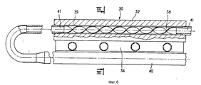
На фиг. 1-3 изображены этапы выполнения герметичного канала в детали из огнеупорного материала в соответствии со способом изготовления охлаждаемого элемента, согласно изобретению; на фиг. 4 изображен схематично вид в разрезе фрагмента установки для регулируемого термоядерного синтеза; на фиг. 5 - конструкция тепловой защиты, составляющей часть стенки камеры на фиг. 4; на фиг. 6 увеличенный вид, в частности, в разрезе, показывающий элемент на фиг. 5 конструкции тепловой защиты; на фиг. 7 частичное сечение по VII-VII на фиг. 6. In FIG. 1-3 depict the stages of the implementation of the sealed channel in the part of the refractory material in accordance with the method of manufacturing the cooled element, according to the invention; in FIG. 4 is a schematic sectional view of a fragment of an apparatus for controlled thermonuclear fusion; in FIG. 5 is a design of thermal protection constituting part of the chamber wall of FIG. 4; in FIG. 6 is an enlarged view, particularly in section, showing the element in FIG. 5 thermal protection designs; in FIG. 7 is a partial section according to VII-VII in FIG. 6.
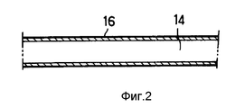
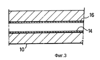
На фиг. 1 позицией 10 обозначена деталь, изготовленная из огнеупорного композитного материала. В детали 10 на стенке выполнено отверстие 12 в том месте, где в ней должен быть выполнен герметичный канал. Металлическое трубчатое внутреннее покрытие или облицовка 14 с покрывающим его внутреннюю поверхность равномерным слоем 16 твердого припоя для высокотемпературной пайки вводится в отверстие 12 (фиг. 2). Сборку затем нагревают до температуры, необходимой для высокотемпературной пайки, и выдерживают при этой температуре в течение соответствующего промежутка времени для обеспечения, во-первых, того, чтобы материал твердого припоя расплавился и вступил в реакцию с композитным материалом и материалом металлического внутреннего покрытия, и, во-вторых, для того, чтобы металл внутреннего покрытия находился в тесном контакте со стенкой отверстия за счет разницы теплового расширения (фиг. 3). В течение высокотемпературной пайки можно подвергнуть металлическую внутреннюю облицовку воздействию внешнего давления. In FIG. 1,
Металлическая внутренняя облицовка 14 изготавливается из металла или металлического сплава, проводящего тепло, например из меди, молибдена и т.п. The metal
Диаметр металлической внутренней облицовки 14 и ее толщину выбирают с учетом выполнения следующих условий:
металлическая внутренняя облицовка, совмещенная со слоем материала твердого припоя, должна быть введена в отверстие с небольшим зазором;
металлическая внутренняя облицовка не должна иметь повреждений после браззинг-процесса; и
контакт между огнеупорным материалом и металлической внутренней облицовкой с напаянным припоем должен быть непрерывным, а разница расширения, имеющая место при использовании детали, должна компенсироваться пластической деформацией металлической внутренней облицовки.The diameter of the metal
metal inner lining, combined with a layer of material of solder, should be introduced into the hole with a small gap;
the metal inner lining should not be damaged after the brazzing process; and
the contact between the refractory material and the metal inner lining with the soldered solder should be continuous, and the expansion difference that occurs when using the part should be compensated by the plastic deformation of the metal inner lining.
Следовательно, толщина металлической внутренней облицовки должна быть больше, чем минимальное значение, ниже которого существует риск того, что она не останется неповрежденной вследствие разъедания материалом твердого пропоя или вследствие давления жидкости в канале. Так как диаметр металлической внутренней облицовки увеличивается, увеличивается и минимальное значение ее толщины. Кроме того, толщина металлической внутренней облицовки должна оставаться меньшей, чем максимальное значение, выше которого облицовка перестает быть пластичной в достаточной степени. Для заданного состава металла минимальное и максимальное значения толщины металлической внутренней облицовки могут быть определены путем эксперимента. Therefore, the thickness of the metal inner lining must be greater than the minimum value, below which there is a risk that it will not remain intact due to corroding by the material of the hard hole or due to the pressure of the liquid in the channel. As the diameter of the metal inner lining increases, the minimum value of its thickness also increases. In addition, the thickness of the metal inner lining should remain less than the maximum value, above which the lining ceases to be sufficiently ductile. For a given metal composition, the minimum and maximum values of the thickness of the metal inner lining can be determined by experiment.
Герметичный канал может быть выполнен в детали, изготовленной из C/C композитного материала при следующих условиях. Деталь из композитного материала изготавливают путем уплотнения армирующих волокон, образованных из слоев ткани из игольчатых кристаллов углерода (патент Франции 2584106). Сначала уплотнение осуществляли путем химической инфильтрации пара (осаждением из парогазовой фазы) с тем, чтобы сформировать отложение или осадок из пиролитического углерода на армирующих волокнах с последующим пропитыванием путем шликерования и пиролизом. Полученный материал подвергали высокотемпературной обработке (графитизации). The sealed channel can be made in a part made of C / C composite material under the following conditions. A component part is made by compaction of reinforcing fibers formed from fabric layers of needle-like carbon crystals (French patent 2584106). First, densification was carried out by chemical vapor infiltration (vapor-gas vapor deposition) so as to form a deposit or precipitate of pyrolytic carbon on reinforcing fibers, followed by impregnation by slip and pyrolysis. The resulting material was subjected to high temperature processing (graphitization).
В детали на станке просверливали прямолинейное отверстие или канал диаметром 11,6 мм общей длиной, равной всей длине детали (200 мм). A straight hole or channel with a diameter of 11.6 mm was drilled into the part on the machine with a total length equal to the entire length of the part (200 mm).
Металлическая внутренняя облицовка представляла собой трубку из мягкой меди с наружным диаметром 11,3 мм и внутренним диаметром 10 мм (толщина 0,65 мм). The metal inner lining was a soft copper tube with an outer diameter of 11.3 mm and an inner diameter of 10 mm (thickness 0.65 mm).
На медную трубку осаждали слой материала твердого припоя толщиной 0,1 мм. В качестве материала твердого припоя использовали припой под названием 4 "Тикусил" ("Ticusil" производства American company GTEWESGO), упомянутый материал твердого припоя базируется на сплаве Ti+Cu+Si+Ag. A 0.1 mm thick layer of brazing material was deposited on a copper tube. As the solder material, a solder called 4 "Ticusil" ("Ticusil" manufactured by American company GTEWESGO) was used, the mentioned solder material is based on the Ti + Cu + Si + Ag alloy.
После введения в отверстие или канал медной трубки, покрытой материалом твердого припоя, сборку, состоящую из детали из композитного материала и медной трубки, нагревали до температуры 890oC и выдерживали при этой температуре в течение 5 мин. При расширении металлическая облицовка, выполненная из меди, впрессовывается в стенку отверстия и принимает форму этой стенки. После охлаждения было видно, что отверстие или канал был полностью облицован медью, находящейся в тесном контакте с огнеупорным композитным материалом, и таким образом был получен совершенно герметичный канал. Также было видно, что металлическая внутренняя облицовка осталась совершенно неповрежденной. Различные испытания показали, что для трубки из мягкой меди с наружным диаметром таким, как описан выше (11,3 мм), толщина стенки трубки должна быть по крайней мере 0,65 мм, поскольку в противном случае очень вероятно, что в металлической внутренней облицовке могут появляться местные трещины и разрывы, при этом толщина стенки должна быть не более чем 1 мм, поскольку в противном случае она не будет достаточно пластичной, а это увеличит количество местных дефектов в ее соединении со стенкой отверстия или канала.After the copper tube coated with the solder material was inserted into the hole or channel, the assembly, consisting of a composite material part and a copper tube, was heated to a temperature of 890 ° C and held at this temperature for 5 minutes. When expanding, a metal cladding made of copper is pressed into the wall of the hole and takes the form of this wall. After cooling, it was seen that the hole or channel was completely lined with copper, which was in close contact with the refractory composite material, and thus a completely sealed channel was obtained. It was also seen that the metal inner lining remained completely intact. Various tests have shown that for a soft copper tube with an outer diameter such as described above (11.3 mm), the tube wall thickness should be at least 0.65 mm, since otherwise it is very likely that the metal inner lining local cracks and tears may appear, while the wall thickness should be no more than 1 mm, because otherwise it will not be sufficiently ductile, and this will increase the number of local defects in its connection with the wall of the hole or channel.
Элемент тепловой защиты, имеющий длину 200 мм и герметичный канал диаметром 10 мм, изготовленный так, как это описано выше, испытывали, используя электронную пушку в условиях высокого теплого потока. После 300 циклов, в течение которых элемент подвергался воздействию установившихся тепловых потоков порядка 11 МВт/м2 и пульсирующих потоков порядка 34 МВт/м2, элемент еще полностью выполнял свои функции.A thermal protection element having a length of 200 mm and a sealed channel with a diameter of 10 mm, manufactured as described above, was tested using an electron gun in high heat flux conditions. After 300 cycles, during which the element was exposed to steady-state heat fluxes of the order of 11 MW / m 2 and pulsating flows of the order of 34 MW / m 2 , the element still fully performed its functions.
Естественно, в этой же детали таким же способом может быть выполнено множество герметичных каналов. Кроме того, возможно выполнение герметичных каналов изогнутыми, а не прямолинейными. Naturally, in the same part in the same way can be made many sealed channels. In addition, it is possible to perform sealed channels curved, rather than straight.
Для образования герметичного канала выше предлагалось начинать с просверливания на стенке отверстия в детали из композитного материала. Однако также возможно оставлять полое отверстие в процессе изготовления детали. Также возможно изготавливать деталь из двух частей, каждая из которых имеет канавку, при этом отверстие образуется при складывании двух частей вместе друг с другом. To form a sealed channel above, it was proposed to start by drilling holes in the composite part on the wall. However, it is also possible to leave a hollow hole in the manufacturing process of the part. It is also possible to produce a part from two parts, each of which has a groove, with the hole being formed when the two parts are folded together.
Способ образования герметичных каналов делает возможным изготовление структур или конструкций из огнеупорного композитного материала, охлаждаемых потоком жидкости. Такие конструкции могут использоваться, в частности, для стенок камер сгорания комбинированных двигателей или для участков аэродинамических конструкций сверхзвуковых космопланов, в частности, на фронтальном конце (носу), вдоль передних кромок крыльев и вокруг обтекателей воздухозаборника. The method of forming sealed channels makes it possible to fabricate structures or structures from a refractory composite material cooled by a fluid stream. Such structures can be used, in particular, for the walls of combustion chambers of combined engines or for sections of the aerodynamic structures of supersonic space planes, in particular at the front end (nose), along the front edges of the wings and around the fairings of the air intake.
Другим применением является изготовление теплозащитных конструкций для очень высокотемпературного оборудования, например камер электромагнитного удерживания плазмы в тороидальных камерах для контролируемого термоядерного синтеза. Another application is the manufacture of heat-shielding structures for very high-temperature equipment, for example, electromagnetic plasma confinement chambers in toroidal chambers for controlled thermonuclear fusion.
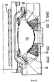
На фиг.4 схематично показано сечение такой камеры. Figure 4 schematically shows a section of such a camera.
Камера удерживания 20 окружена индукционными катушками 22 и 24 и соединена каналом 26 с источником вакуума. Внутренняя стенка камеры 20 укрыта тепловой защитой. На верхней и нижней частях камеры каждый участок образующей отражатель 28 внутренней стенки является зоной, подвергаемой воздействию особенно высоких напряжений. Как показано на фиг.4, линии электромагнитного поля пересекаются в этой зоне. Удержание здесь менее интенсивное, поскольку отражатель подвергается воздействию очень высоких тепловых потоков. Тепловая защита на каждом отражателе выполняет функции защиты стенки камеры. Температура поверхности тепловой защиты тем не менее не должна превышать 1000-1200oC для того, чтобы избежать загрязнения плазмы за счет сублимации материала защиты. Поэтому тепловую защиту преимущественно составляет конструкция, выполненная из огнеупорного композитного материала и охлаждаемая потоком жидкости.The holding chamber 20 is surrounded by
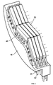
На фиг. 5 фрагментарно в увеличенном масштабе показана тепловая защита одного из отражателей 28. Она собрана из идентичных унитарных элементов 30, каждый из которых имеет выполненный в нем канал для протекания потока охлаждающей жидкости. Эти каналы соединены с системой трубопроводов 40, 42 для подачи и распределения охлаждающей жидкости, при этом такой жидкостью может быть вода при температуре 150oC и давлении 30 50 бар.In FIG. 5 fragmentary on an enlarged scale shows the thermal protection of one of the
В показанном примере элементы 30 размещены зигзагообразно во множестве рядов, которые плотно подогнаны друг к другу для профилирования стенки камеры. Охлаждающая жидкость подается к одному концу каждой линии и удаляется из противоположного конца этой линии. Элементы 30 смонтированы на металлической опорной конструкции 44, которая крепится к стенке 46 камеры. In the shown example, the
Элемент 30 изображен на фиг. 6 и 7. Он содержит профилированную балку 32 из огнеупорного композитного материала, например типа C/C. В основании балка 32 имеет фиксирующее ребро 34, в котором пробиты отверстия 36 для обеспечения возможности монтажа с помощью системы гаек и болтов на опорной конструкции. В балке 32 выполнен, как это описано со ссылкой на фиг. 1-3, герметичный канал 38, при этом герметизация выполнена посредством высокотемпературной пайки твердым припоем (браззинг-процессом) металлической внутренней облицовки 39, выполненной из меди. Канал 38 соединен с трубопроводом 40 или 42 или с герметичным каналом в соседнем элементе посредством муфт 41, приваренных к концам металлической внутренней облицовки 39. Муфты или переходники 41 изготовлены из меди, т.е. из того же материала, что и внутренняя облицовка 39, и они присоединены к концам канала 38 посредством сварки электронным лучом. Трубопроводы 40 и 42 изготовлены из труб из нержавеющей стали, которые приварены сваркой трением к медным муфтам или переходникам 41.
Claims (14)
Applications Claiming Priority (3)
| Application Number | Priority Date | Filing Date | Title |
|---|---|---|---|
| FR9116390A FR2685655B1 (en) | 1991-12-31 | 1991-12-31 | PROCESS FOR FORMING A SEALED PASSAGE IN A PIECE IN REFRACTORY COMPOSITE MATERIAL, AND APPLICATION TO THE PRODUCTION OF A REFRACTORY COMPOSITE STRUCTURE COOLED BY FLUID CIRCULATION. |
| FR9116390 | 1991-12-31 | ||
| PCT/FR1992/001243 WO1993013636A1 (en) | 1991-12-31 | 1992-12-30 | Method for making a sealed passage in a refractory composite part, and application to the production of a refractory composite structure cooled by fluid circulation |
Publications (2)
| Publication Number | Publication Date |
|---|---|
| RU94031201A RU94031201A (en) | 1996-05-27 |
| RU2101887C1 true RU2101887C1 (en) | 1998-01-10 |
Family
ID=9420712
Family Applications (1)
| Application Number | Title | Priority Date | Filing Date |
|---|---|---|---|
| RU94031201A RU2101887C1 (en) | 1991-12-31 | 1992-12-30 | Heat shield, cooling element and its manufacturing process |
Country Status (10)
| Country | Link |
|---|---|
| US (3) | US5583895A (en) |
| EP (1) | EP0628235B1 (en) |
| JP (1) | JP3250668B2 (en) |
| CA (1) | CA2127245C (en) |
| DE (2) | DE69218257T4 (en) |
| ES (1) | ES2099442T3 (en) |
| FR (1) | FR2685655B1 (en) |
| RU (1) | RU2101887C1 (en) |
| UA (1) | UA26342C2 (en) |
| WO (1) | WO1993013636A1 (en) |
Cited By (1)
| Publication number | Priority date | Publication date | Assignee | Title |
|---|---|---|---|---|
| RU2634307C1 (en) * | 2016-05-27 | 2017-10-25 | Российская Федерация, от имени которой выступает Государственная корпорация по атомной энергии "Росатом" | Device for researching thermohydraulic characteristics of liquid-metallic blanket of tyar |
Families Citing this family (10)
| Publication number | Priority date | Publication date | Assignee | Title |
|---|---|---|---|---|
| AT400909B (en) * | 1994-01-17 | 1996-04-25 | Plansee Ag | METHOD FOR PRODUCING A COOLING DEVICE |
| FR2782378B1 (en) | 1998-08-14 | 2000-11-10 | Snecma | STRUCTURAL PART COMPRISING A PART OF THERMOSTRUCTURAL COMPOSITE MATERIAL COOLED BY FLUID CIRCULATION |
| FR2785664B1 (en) | 1998-11-05 | 2001-02-02 | Snecma | COMPOSITE MATERIAL HEAT EXCHANGER AND METHOD FOR THE PRODUCTION THEREOF |
| FR2836699B1 (en) | 2002-03-04 | 2005-02-11 | Eads Launch Vehicles | ENGINE OF ROCKET |
| FR2836698B1 (en) * | 2002-03-04 | 2005-02-11 | Eads Launch Vehicles | COMBUSTION CHAMBER FOR STATOREACTOR AND STATOREACTOR PROVIDED WITH SUCH A COMBUSTION CHAMBER |
| FR2850741B1 (en) * | 2003-01-30 | 2005-09-23 | Snecma Propulsion Solide | PROCESS FOR MANUFACTURING AN ACTIVE COOLING PANEL OF THERMOSTRUCTURAL COMPOSITE MATERIAL |
| US7117680B2 (en) * | 2004-04-22 | 2006-10-10 | United Technologies Corporation | Cooling scheme for scramjet variable geometry hardware |
| US7331381B2 (en) * | 2006-02-16 | 2008-02-19 | Allcomp, Inc. | Hybrid heat exchangers |
| US8212062B2 (en) | 2007-04-02 | 2012-07-03 | Inventure Chemical, Inc. | Production of biodiesel, cellulosic sugars, and peptides from the simultaneous esterification and alcoholysis/hydrolysis of oil-containing materials with cellulosic and peptidic content |
| US7943792B2 (en) * | 2007-04-02 | 2011-05-17 | Inventure Chemical Inc. | Production of biodiesel, cellulosic sugars, and peptides from the simultaneous esterification and alcoholysis/hydrolysis of materials with oil-containing substituents including phospholipids and peptidic content |
Family Cites Families (6)
| Publication number | Priority date | Publication date | Assignee | Title |
|---|---|---|---|---|
| DE3416843A1 (en) * | 1984-05-07 | 1985-11-14 | Max-Planck-Gesellschaft zur Förderung der Wissenschaften e.V., 3400 Göttingen | ACTIVE COOLED HEAT SHIELD |
| US4852645A (en) * | 1986-06-16 | 1989-08-01 | Le Carbone Lorraine | Thermal transfer layer |
| DE68929046T2 (en) * | 1988-04-28 | 1999-12-23 | Mitsubishi Heavy Ind Ltd | Carbon fiber reinforced carbon composites, processes for their manufacture and their use as inner walls of nuclear fusion reactors |
| DE3828902A1 (en) * | 1988-08-25 | 1990-03-08 | Max Planck Gesellschaft | HEAT SHIELD |
| JPH0814633B2 (en) * | 1989-05-24 | 1996-02-14 | 株式会社日立製作所 | Nuclear fusion reactor |
| FR2664585B1 (en) * | 1990-07-13 | 1993-08-06 | Europ Propulsion | COOLED REFRACTORY STRUCTURES AND METHOD FOR THEIR MANUFACTURE. |
-
1991
- 1991-12-31 FR FR9116390A patent/FR2685655B1/en not_active Expired - Fee Related
-
1992
- 1992-12-30 WO PCT/FR1992/001243 patent/WO1993013636A1/en active IP Right Grant
- 1992-12-30 US US08/256,253 patent/US5583895A/en not_active Expired - Lifetime
- 1992-12-30 EP EP93911665A patent/EP0628235B1/en not_active Expired - Lifetime
- 1992-12-30 UA UA94005337A patent/UA26342C2/en unknown
- 1992-12-30 JP JP51150493A patent/JP3250668B2/en not_active Expired - Fee Related
- 1992-12-30 ES ES93911665T patent/ES2099442T3/en not_active Expired - Lifetime
- 1992-12-30 CA CA002127245A patent/CA2127245C/en not_active Expired - Fee Related
- 1992-12-30 DE DE69218257T patent/DE69218257T4/en not_active Expired - Lifetime
- 1992-12-30 DE DE69218257A patent/DE69218257D1/en not_active Expired - Lifetime
- 1992-12-30 RU RU94031201A patent/RU2101887C1/en not_active IP Right Cessation
-
1995
- 1995-06-06 US US08/471,648 patent/US5604776A/en not_active Expired - Lifetime
-
1996
- 1996-07-24 US US08/685,544 patent/US5778033A/en not_active Expired - Lifetime
Non-Patent Citations (1)
| Title |
|---|
| US, А, 5023043, кл. G 21 B 1/00 1991. * |
Cited By (1)
| Publication number | Priority date | Publication date | Assignee | Title |
|---|---|---|---|---|
| RU2634307C1 (en) * | 2016-05-27 | 2017-10-25 | Российская Федерация, от имени которой выступает Государственная корпорация по атомной энергии "Росатом" | Device for researching thermohydraulic characteristics of liquid-metallic blanket of tyar |
Also Published As
| Publication number | Publication date |
|---|---|
| WO1993013636A1 (en) | 1993-07-08 |
| JPH07502597A (en) | 1995-03-16 |
| US5583895A (en) | 1996-12-10 |
| RU94031201A (en) | 1996-05-27 |
| US5604776A (en) | 1997-02-18 |
| US5778033A (en) | 1998-07-07 |
| DE69218257D1 (en) | 1997-04-17 |
| FR2685655B1 (en) | 1995-08-18 |
| EP0628235A1 (en) | 1994-12-14 |
| DE69218257T2 (en) | 1997-06-19 |
| DE69218257T4 (en) | 1997-10-23 |
| EP0628235B1 (en) | 1997-03-12 |
| ES2099442T3 (en) | 1997-05-16 |
| CA2127245A1 (en) | 1993-07-08 |
| FR2685655A1 (en) | 1993-07-02 |
| UA26342C2 (en) | 1999-08-30 |
| JP3250668B2 (en) | 2002-01-28 |
| CA2127245C (en) | 1999-10-19 |
Similar Documents
| Publication | Publication Date | Title |
|---|---|---|
| RU2101887C1 (en) | Heat shield, cooling element and its manufacturing process | |
| US6758386B2 (en) | Method of joining ceramic matrix composites and metals | |
| CA2619437C (en) | Gasifier liner | |
| JP4249396B2 (en) | Heat exchanger made of composite material and method of manufacturing the same | |
| US6151887A (en) | Combustion chamber for rocket engine | |
| US5842342A (en) | Fiber reinforced ceramic matrix composite internal combustion engine intake/exhaust port liners | |
| US4895108A (en) | CVD apparatus and process for the preparation of fiber-reinforced ceramic composites | |
| US8276621B2 (en) | Element for a pipe for transporting hot gases and method of fabricating said element | |
| US5230306A (en) | Ceramic sootblower element | |
| US20040194941A1 (en) | Active cooling panel of thermostructural composite material and method for its manufacture | |
| JP2004233044A (en) | Method of manufacturing active cooling panel using thermostructural composite material | |
| US4189301A (en) | Reinforced insulating members | |
| RU2273756C2 (en) | Component of rocket engine and method for manufacture of rocket engine component | |
| Miyajima et al. | Performance of a low thrust LO2/LH2 engine with a 300: 1 area ratio nozzle | |
| JPH102695A (en) | High pressure heat exchanger |
Legal Events
| Date | Code | Title | Description |
|---|---|---|---|
| MM4A | The patent is invalid due to non-payment of fees |
Effective date: 20071231 |