RU2100221C1 - Vehicle - Google Patents
Vehicle Download PDFInfo
- Publication number
- RU2100221C1 RU2100221C1 RU9494018703A RU94018703A RU2100221C1 RU 2100221 C1 RU2100221 C1 RU 2100221C1 RU 9494018703 A RU9494018703 A RU 9494018703A RU 94018703 A RU94018703 A RU 94018703A RU 2100221 C1 RU2100221 C1 RU 2100221C1
- Authority
- RU
- Russia
- Prior art keywords
- power
- vehicle according
- power source
- vehicle
- switching
- Prior art date
Links
Images
Classifications
-
- B—PERFORMING OPERATIONS; TRANSPORTING
- B60—VEHICLES IN GENERAL
- B60K—ARRANGEMENT OR MOUNTING OF PROPULSION UNITS OR OF TRANSMISSIONS IN VEHICLES; ARRANGEMENT OR MOUNTING OF PLURAL DIVERSE PRIME-MOVERS IN VEHICLES; AUXILIARY DRIVES FOR VEHICLES; INSTRUMENTATION OR DASHBOARDS FOR VEHICLES; ARRANGEMENTS IN CONNECTION WITH COOLING, AIR INTAKE, GAS EXHAUST OR FUEL SUPPLY OF PROPULSION UNITS IN VEHICLES
- B60K6/00—Arrangement or mounting of plural diverse prime-movers for mutual or common propulsion, e.g. hybrid propulsion systems comprising electric motors and internal combustion engines ; Control systems therefor, i.e. systems controlling two or more prime movers, or controlling one of these prime movers and any of the transmission, drive or drive units Informative references: mechanical gearings with secondary electric drive F16H3/72; arrangements for handling mechanical energy structurally associated with the dynamo-electric machine H02K7/00; machines comprising structurally interrelated motor and generator parts H02K51/00; dynamo-electric machines not otherwise provided for in H02K see H02K99/00
- B60K6/20—Arrangement or mounting of plural diverse prime-movers for mutual or common propulsion, e.g. hybrid propulsion systems comprising electric motors and internal combustion engines ; Control systems therefor, i.e. systems controlling two or more prime movers, or controlling one of these prime movers and any of the transmission, drive or drive units Informative references: mechanical gearings with secondary electric drive F16H3/72; arrangements for handling mechanical energy structurally associated with the dynamo-electric machine H02K7/00; machines comprising structurally interrelated motor and generator parts H02K51/00; dynamo-electric machines not otherwise provided for in H02K see H02K99/00 the prime-movers consisting of electric motors and internal combustion engines, e.g. HEVs
- B60K6/42—Arrangement or mounting of plural diverse prime-movers for mutual or common propulsion, e.g. hybrid propulsion systems comprising electric motors and internal combustion engines ; Control systems therefor, i.e. systems controlling two or more prime movers, or controlling one of these prime movers and any of the transmission, drive or drive units Informative references: mechanical gearings with secondary electric drive F16H3/72; arrangements for handling mechanical energy structurally associated with the dynamo-electric machine H02K7/00; machines comprising structurally interrelated motor and generator parts H02K51/00; dynamo-electric machines not otherwise provided for in H02K see H02K99/00 the prime-movers consisting of electric motors and internal combustion engines, e.g. HEVs characterised by the architecture of the hybrid electric vehicle
- B60K6/46—Series type
-
- B—PERFORMING OPERATIONS; TRANSPORTING
- B60—VEHICLES IN GENERAL
- B60L—PROPULSION OF ELECTRICALLY-PROPELLED VEHICLES; SUPPLYING ELECTRIC POWER FOR AUXILIARY EQUIPMENT OF ELECTRICALLY-PROPELLED VEHICLES; ELECTRODYNAMIC BRAKE SYSTEMS FOR VEHICLES IN GENERAL; MAGNETIC SUSPENSION OR LEVITATION FOR VEHICLES; MONITORING OPERATING VARIABLES OF ELECTRICALLY-PROPELLED VEHICLES; ELECTRIC SAFETY DEVICES FOR ELECTRICALLY-PROPELLED VEHICLES
- B60L50/00—Electric propulsion with power supplied within the vehicle
- B60L50/10—Electric propulsion with power supplied within the vehicle using propulsion power supplied by engine-driven generators, e.g. generators driven by combustion engines
- B60L50/13—Electric propulsion with power supplied within the vehicle using propulsion power supplied by engine-driven generators, e.g. generators driven by combustion engines using AC generators and AC motors
-
- B—PERFORMING OPERATIONS; TRANSPORTING
- B60—VEHICLES IN GENERAL
- B60L—PROPULSION OF ELECTRICALLY-PROPELLED VEHICLES; SUPPLYING ELECTRIC POWER FOR AUXILIARY EQUIPMENT OF ELECTRICALLY-PROPELLED VEHICLES; ELECTRODYNAMIC BRAKE SYSTEMS FOR VEHICLES IN GENERAL; MAGNETIC SUSPENSION OR LEVITATION FOR VEHICLES; MONITORING OPERATING VARIABLES OF ELECTRICALLY-PROPELLED VEHICLES; ELECTRIC SAFETY DEVICES FOR ELECTRICALLY-PROPELLED VEHICLES
- B60L50/00—Electric propulsion with power supplied within the vehicle
- B60L50/50—Electric propulsion with power supplied within the vehicle using propulsion power supplied by batteries or fuel cells
- B60L50/60—Electric propulsion with power supplied within the vehicle using propulsion power supplied by batteries or fuel cells using power supplied by batteries
- B60L50/61—Electric propulsion with power supplied within the vehicle using propulsion power supplied by batteries or fuel cells using power supplied by batteries by batteries charged by engine-driven generators, e.g. series hybrid electric vehicles
-
- B—PERFORMING OPERATIONS; TRANSPORTING
- B60—VEHICLES IN GENERAL
- B60L—PROPULSION OF ELECTRICALLY-PROPELLED VEHICLES; SUPPLYING ELECTRIC POWER FOR AUXILIARY EQUIPMENT OF ELECTRICALLY-PROPELLED VEHICLES; ELECTRODYNAMIC BRAKE SYSTEMS FOR VEHICLES IN GENERAL; MAGNETIC SUSPENSION OR LEVITATION FOR VEHICLES; MONITORING OPERATING VARIABLES OF ELECTRICALLY-PROPELLED VEHICLES; ELECTRIC SAFETY DEVICES FOR ELECTRICALLY-PROPELLED VEHICLES
- B60L9/00—Electric propulsion with power supply external to the vehicle
- B60L9/02—Electric propulsion with power supply external to the vehicle using dc motors
- B60L9/08—Electric propulsion with power supply external to the vehicle using dc motors fed from ac supply lines
-
- B—PERFORMING OPERATIONS; TRANSPORTING
- B60—VEHICLES IN GENERAL
- B60L—PROPULSION OF ELECTRICALLY-PROPELLED VEHICLES; SUPPLYING ELECTRIC POWER FOR AUXILIARY EQUIPMENT OF ELECTRICALLY-PROPELLED VEHICLES; ELECTRODYNAMIC BRAKE SYSTEMS FOR VEHICLES IN GENERAL; MAGNETIC SUSPENSION OR LEVITATION FOR VEHICLES; MONITORING OPERATING VARIABLES OF ELECTRICALLY-PROPELLED VEHICLES; ELECTRIC SAFETY DEVICES FOR ELECTRICALLY-PROPELLED VEHICLES
- B60L2200/00—Type of vehicles
- B60L2200/26—Rail vehicles
-
- B—PERFORMING OPERATIONS; TRANSPORTING
- B60—VEHICLES IN GENERAL
- B60L—PROPULSION OF ELECTRICALLY-PROPELLED VEHICLES; SUPPLYING ELECTRIC POWER FOR AUXILIARY EQUIPMENT OF ELECTRICALLY-PROPELLED VEHICLES; ELECTRODYNAMIC BRAKE SYSTEMS FOR VEHICLES IN GENERAL; MAGNETIC SUSPENSION OR LEVITATION FOR VEHICLES; MONITORING OPERATING VARIABLES OF ELECTRICALLY-PROPELLED VEHICLES; ELECTRIC SAFETY DEVICES FOR ELECTRICALLY-PROPELLED VEHICLES
- B60L2200/00—Type of vehicles
- B60L2200/40—Working vehicles
-
- Y—GENERAL TAGGING OF NEW TECHNOLOGICAL DEVELOPMENTS; GENERAL TAGGING OF CROSS-SECTIONAL TECHNOLOGIES SPANNING OVER SEVERAL SECTIONS OF THE IPC; TECHNICAL SUBJECTS COVERED BY FORMER USPC CROSS-REFERENCE ART COLLECTIONS [XRACs] AND DIGESTS
- Y02—TECHNOLOGIES OR APPLICATIONS FOR MITIGATION OR ADAPTATION AGAINST CLIMATE CHANGE
- Y02P—CLIMATE CHANGE MITIGATION TECHNOLOGIES IN THE PRODUCTION OR PROCESSING OF GOODS
- Y02P90/00—Enabling technologies with a potential contribution to greenhouse gas [GHG] emissions mitigation
- Y02P90/60—Electric or hybrid propulsion means for production processes
-
- Y—GENERAL TAGGING OF NEW TECHNOLOGICAL DEVELOPMENTS; GENERAL TAGGING OF CROSS-SECTIONAL TECHNOLOGIES SPANNING OVER SEVERAL SECTIONS OF THE IPC; TECHNICAL SUBJECTS COVERED BY FORMER USPC CROSS-REFERENCE ART COLLECTIONS [XRACs] AND DIGESTS
- Y02—TECHNOLOGIES OR APPLICATIONS FOR MITIGATION OR ADAPTATION AGAINST CLIMATE CHANGE
- Y02T—CLIMATE CHANGE MITIGATION TECHNOLOGIES RELATED TO TRANSPORTATION
- Y02T10/00—Road transport of goods or passengers
- Y02T10/60—Other road transportation technologies with climate change mitigation effect
- Y02T10/62—Hybrid vehicles
-
- Y—GENERAL TAGGING OF NEW TECHNOLOGICAL DEVELOPMENTS; GENERAL TAGGING OF CROSS-SECTIONAL TECHNOLOGIES SPANNING OVER SEVERAL SECTIONS OF THE IPC; TECHNICAL SUBJECTS COVERED BY FORMER USPC CROSS-REFERENCE ART COLLECTIONS [XRACs] AND DIGESTS
- Y02—TECHNOLOGIES OR APPLICATIONS FOR MITIGATION OR ADAPTATION AGAINST CLIMATE CHANGE
- Y02T—CLIMATE CHANGE MITIGATION TECHNOLOGIES RELATED TO TRANSPORTATION
- Y02T10/00—Road transport of goods or passengers
- Y02T10/60—Other road transportation technologies with climate change mitigation effect
- Y02T10/70—Energy storage systems for electromobility, e.g. batteries
-
- Y—GENERAL TAGGING OF NEW TECHNOLOGICAL DEVELOPMENTS; GENERAL TAGGING OF CROSS-SECTIONAL TECHNOLOGIES SPANNING OVER SEVERAL SECTIONS OF THE IPC; TECHNICAL SUBJECTS COVERED BY FORMER USPC CROSS-REFERENCE ART COLLECTIONS [XRACs] AND DIGESTS
- Y02—TECHNOLOGIES OR APPLICATIONS FOR MITIGATION OR ADAPTATION AGAINST CLIMATE CHANGE
- Y02T—CLIMATE CHANGE MITIGATION TECHNOLOGIES RELATED TO TRANSPORTATION
- Y02T10/00—Road transport of goods or passengers
- Y02T10/60—Other road transportation technologies with climate change mitigation effect
- Y02T10/7072—Electromobility specific charging systems or methods for batteries, ultracapacitors, supercapacitors or double-layer capacitors
Abstract
Description
Изобретение относится к самодвижущимся транспортным средствам или электромобилям, использующим для питания электроэнергию от внешнего источника. The invention relates to self-propelled vehicles or electric vehicles that use electricity from an external source to power.
Самодвижущиеся транспортные средства или электромобили, питаемые внешней энергией, вообще часто применяются в промышленности, особенно в горной индустрии, в которой требования безопасности препятствуют или ограничивают использование под землей автомобилей, воспринимающих энергию от встроенных двигателей внутреннего сгорания. Такие электромобили обычно получают электроэнергию от внешней контактной сети или подсоединенного волочащегося кабеля, который передает переменный ток. Контактная сеть обычно используется буксировочными тягачами, а кабели копающими машинами. Переменный ток может применяться для питания электродвигателя переменного тока или может быть выпрямлен для питания электродвигателя постоянного тока. Self-propelled vehicles or electric vehicles powered by external energy are generally often used in industry, especially in the mining industry, in which safety requirements hinder or limit the use underground of vehicles that receive energy from internal combustion engines. Such electric vehicles typically receive electricity from an external contact network or a connected dragging cable that transmits alternating current. The contact network is usually used by towing tractors, and cables by digging machines. Alternating current may be used to power an alternating current electric motor or may be rectified to supply a direct current electric motor.
Существующие автомобили, использующие двигатели переменного тока, имеют некоторые недостатки с точки зрения их управляемости. Ранее существовавшие контроллеры переменного тока были бесполезны или не удобны для подвижного автотранспорта из-за их размеров, сложности и чувствительности к воздействию окружающей среды, особенно к ускорению и механическому удару. В результате такие системы использовались только для складских систем монорельсового типа и поисковых систем, имеющих ограниченную мобильность в пределах ограниченной траектории, например, вдоль единственного прохода в автоматизированном товарном складе. В подобных системах контроллер не транспортируется на машине, а параметры окружающей среды легко контролируются. Existing cars using AC motors have some drawbacks in terms of their controllability. Previously existing AC controllers were useless or not suitable for mobile vehicles because of their size, complexity and sensitivity to environmental influences, especially to acceleration and mechanical shock. As a result, such systems were used only for monorail-type storage systems and search engines that have limited mobility within a limited path, for example, along a single passage in an automated warehouse. In such systems, the controller is not transported by car, and environmental parameters are easily controlled.
При таких скоростях электродвигатели переменного тока чувствительны к "зубчатости" статора, которая нарушает равномерный режим работы. Электродвигатели переменного тока использовались в электромобилях, но это были двигатели с постоянной скоростью. Следовательно, они требовали сложной трансмиссии и техники управления сцеплением, применяемой искусными водителями для управления автомобилем при переменной скорости. At these speeds, AC motors are sensitive to stator “jaggedness,” which disrupts uniform operation. AC motors were used in electric cars, but they were motors with constant speed. Consequently, they required a sophisticated transmission and clutch control technique used by skilled drivers to drive a car at variable speed.
Электродвигатели постоянного тока, с другой стороны, легко управляются. Однако, на практике они требуют неэффективного преобразования энергии переменного тока в постоянный ток. Такие системы преобразования переменного тока в постоянный ток представлены, например, (патент США, 4483148, кл. F 01 B 21/04, 1984). DC motors, on the other hand, are easy to control. However, in practice, they require inefficient conversion of AC energy into direct current. Such systems for converting alternating current to direct current are presented, for example, (US Pat. No. 4,483,148, class F 01
К тому же электродвигатели постоянного тока более сложны, чем электродвигатели переменного тока из-за щеток, которые склонны к износу. В результате они более дороги в эксплуатации и менее надежны, чем электродвигатели переменного тока. Использование контактной сети также не годится для обеспечения энергией постоянного тока от внешнего источника по причине потерь энергии из-за сопротивления линии, особенно на длинных линиях. In addition, DC motors are more complex than AC motors because of brushes that are prone to wear. As a result, they are more expensive to operate and less reliable than AC motors. The use of a contact network is also not suitable for providing DC power from an external source due to energy losses due to line resistance, especially on long lines.
Некоторые системы предыдущего уровня техники используют двигатели и переменного, и постоянного тока, чтобы извлечь пользу из преимуществ обеих систем. Однако, это достигается ценой дополнительной сложности и избыточности, (Патент, США, 4099589, кл. В 60 K 9/04, 1978), например, показывает электромобиль с приводными электродвигателями переменного и постоянного тока. Машина может приводиться в движение двигателем постоянного тока при движении на коротком интервале "разгона-торможения", когда важна управляемость, и может приводиться в движение электродвигателем переменного тока при движении на длинные расстояния с относительно постоянной скоростью, когда главный критерий эффективность. Использование избыточных двигателей, однако, существенно увеличивает цену, при этом оба двигателя рассчитаны на наличие бортового встроенного двигателя внутреннего сгорания для выработки электроэнергии. Some prior art systems use both AC and DC motors to benefit from the advantages of both systems. However, this is achieved at the cost of additional complexity and redundancy, (Patent, USA, 4099589, class. 60 K 9/04, 1978), for example, shows an electric car with AC and DC drive motors. The machine can be driven by a DC motor when driving over a short “acceleration-braking” interval, when controllability is important, and can be driven by an AC motor when driving long distances at a relatively constant speed, when the main criterion is efficiency. The use of excess engines, however, significantly increases the price, while both engines are designed for the presence of an onboard built-in internal combustion engine to generate electricity.
Наиболее близким к описываемому является транспортное средство с двойным электропитанием, содержащее индивидуальные для колес или колесных пар тяговые электродвигатели переменного тока, непосредственно с ними связанные, токоприемник, предназначенный для подключения к внешнему источнику электроэнергии переменного тока, контроллеры скорости, включенные в цепи питания тяговых электродвигателей, бортовой источник электроэнергии переменного тока (заявка ФРГ, 2629840, кл. В 60 L 9/00, 1979). Closest to the described is a vehicle with dual power supply, containing traction AC motors individual for wheels or wheelsets, directly connected to them, a current collector designed to connect to an external AC power source, speed controllers included in the power supply circuit of traction motors, onboard AC power source (German application, 2629840, class B 60 L 9/00, 1979).
Однако известное техническое решение предопределяет ограниченные функциональные возможности и невысокие технические характеристики транспортного средства, что позволяет его использовать лишь в качестве городского троллейбуса. However, the known technical solution predetermines the limited functionality and low technical characteristics of the vehicle, which allows it to be used only as an urban trolley.
Задачей изобретения является создание электромобиля, имеющего электромотор переменного тока в качестве своего главного привода в то время, когда транспортное средство подсоединено к контактной сети. Электродвигатель переменного тока подключен к бортовому контроллеру регулирования скорости и, в предпочтительном варианте реализации, может переключаться на вспомогательный бортовой источник энергии переменного тока, когда автотранспорт отсоединен от контактной сети. The objective of the invention is the creation of an electric vehicle having an alternating current electric motor as its main drive while the vehicle is connected to the contact network. The AC motor is connected to an on-board speed controller and, in a preferred embodiment, can switch to an auxiliary on-board AC power source when the vehicle is disconnected from the contact network.
Речь идет о реализации транспортного средства:
с электроприводом, приводимого в движение двигателем переменного тока с регулируемой скоростью, который работает равномерно и эффективно на всех скоростях,
которое может питаться внешней электроэнергией от контактной сети,
имеет вспомогательный бортовой источник энергии;
в котором вспомогательный бортовой источник энергии содержит средство для подачи резервного электропитания переменного тока в приводной двигатель переменного тока с регулируемой скоростью,
которое включает в себя бортовое средство для разделения и переключения с энергии контактной сети на бортовую вспомогательную энергию и обратно.It is about selling a vehicle:
with an electric drive driven by a variable speed AC motor that works uniformly and efficiently at all speeds,
which can be powered by external electricity from the contact network,
has an auxiliary onboard power source;
wherein the auxiliary onboard power source comprises means for supplying alternating current backup power to the variable speed drive AC motor,
which includes on-board means for separating and switching from the energy of the contact network to the on-board auxiliary energy and vice versa.
Поставленная задача решается таким образом, что в транспортное средство с двойным электропитанием, содержащее индивидуальные для колес или колесных пар тяговые электродвигатели переменного тока, непосредственно с ними связанные, токоприемник, предназначенный для подключения к внешнему источнику электроэнергии переменного тока, контроллеры скорости, включенные в цепи питания тяговых электродвигателей, бортовой источник электроэнергии переменного тока, введены узел переключения питания и программируемый контроллер переключения, а контроллеры скорости выполнены с возможностью регулирования частоты переменного тока, при этом силовые входы узла переключения питания соединены с выводами токоприемника и бортового источника электроэнергии, а силовой выход с входами контроллеров скорости, контроллер переключения взаимосвязан по цепям управления с узлом переключения питания, контроллерами скорости и бортовым источником электроэнергии. The problem is solved in such a way that in a vehicle with dual power supply, containing traction AC motors that are individual for wheels or wheelsets, directly connected with them, a current collector designed to connect to an external AC power source, speed controllers included in the power circuit traction electric motors, an on-board AC power source, a power switching unit and a programmable switching controller were introduced, and speed controllers are configured to control the frequency of the alternating current, while the power inputs of the power switching unit are connected to the terminals of the current collector and the onboard power source, and the power output with the inputs of the speed controllers, the switching controller is interconnected via control circuits with the power switching unit, speed controllers and the onboard source electricity.
При этом к силовому выходу узла переключения питания подключен вспомогательный электродвигатель. Со вспомогательным электродвигателем кинематически связан гидравлический насос, предназначенный для создания давления в гидравлической системе транспортного средства. Бортовой источник электроэнергии включает в себя встроенный двигатель внутреннего сгорания и кинематически с ним связанный генератор переменного тока. Токоприемник выполнен с возможностью токосъема с проводов контактной сети. Контроллер переключения включает в себя блок управления узлом переключения питания, выполненный с возможностью его перевода из одной позиции в другую. Блок управления контроллера переключения выполнен с возможностью перевода узла переключения питания на позицию соединения с бортовым источником электроэнергии лишь при наличии электроэнергии на выходе последнего. Контроллер переключения включает в себя датчик переменного тока бортового источника электроэнергии и выполнен с возможностью синхронизации бортового источника электроэнергии и контактной сети с использованием сигналов датчика тока. At the same time, an auxiliary electric motor is connected to the power output of the power switching unit. A hydraulic pump kinematically connected to the auxiliary electric motor is designed to create pressure in the hydraulic system of the vehicle. The on-board power source includes an internal combustion engine and a kinematically connected alternating current generator. The current collector is made with the possibility of current collection from the wires of the contact network. The switching controller includes a control unit for the power switching unit, configured to transfer it from one position to another. The control unit of the switching controller is configured to transfer the power switching unit to the position of connection with the on-board power source only if there is electricity at the output of the latter. The switching controller includes an alternating current sensor of the onboard power source and is configured to synchronize the onboard power source and the contact network using current sensor signals.
Поставленная задача решается также тем, что в транспортное средство с двойным электропитанием, содержащее общий для всех колес тяговый электродвигатель переменного тока, связанный с ними посредством трансмиссии, токоприемник, предназначенный для подключения к внешнему источнику электроэнергии переменного тока, контроллер скорости, включенный в цепь питания тягового электродвигателя, бортовой источник электроэнергии переменного тока, введены узел переключения питания и программируемый контроллер переключения, а контроллер скорости выполнен с возможностью регулирования частоты переменного тока, при этом силовые входы узла переключения питания соединены с выводами токоприемника и бортового источника электроэнергии, а силовой выход с входом контроллера скорости, контроллер переключения взаимосвязан по цепям управления с узлом переключения питания, контроллером скорости и бортовым источником электроэнергии. The problem is also solved by the fact that in a vehicle with dual power supply, containing a common for all wheels traction AC motor connected to them through a transmission, a current collector designed to connect to an external AC power source, a speed controller included in the traction power circuit an electric motor, an onboard AC power source, a power switching unit and a programmable switching controller, and a speed controller were introduced is adapted to regulate the frequency of the alternating current, the power input node switching power supply are connected to the terminals of the susceptor and on-board power source and the power output from the speed controller input, the switching controller is interconnected by control circuits from the power supply switch unit, the speed controller and the onboard electric power source.
При этом к силовому выходу узла переключения питания подключен вспомогательный электродвигатель. Со вспомогательным электродвигателем кинематически связан гидравлический насос, предназначенный для создания давления в гидравлической системе транспортного средства. Со вспомогательным электродвигателем кинематически связан генератор постоянного тока, предназначенный для электроснабжения системы оперативного постоянного тока транспортного средства. Бортовой источник электроэнергии включает в себя встроенный двигатель внутреннего сгорания и кинематически связанный с ним генератор переменного тока. Бортовой источник электроэнергии включает в себя последовательно соединенные источник постоянного тока и инвертор. Токоприемник выполнен с возможностью токосъема с проводов контактной сети. Контроллер переключения включает в себя блок управления узлом переключения питания, выполненный с возможностью его перевода из одной позиции в другую. Блок управления контроллера переключения выполнен с возможностью перевода узла переключения питания на позицию соединения с бортовым источником электроэнергии лишь при наличии электроэнергии на выходе последнего. Контроллер переключения включает в себя датчик переменного тока бортового источника электроэнергии. Контроллер переключения включает в себя блок регулирования величины переменного тока бортового источника электроэнергии. Контроллер переключения включает в себя блок регулирования частоты переменного тока бортового источника электроэнергии. At the same time, an auxiliary electric motor is connected to the power output of the power switching unit. A hydraulic pump kinematically connected to the auxiliary electric motor is designed to create pressure in the hydraulic system of the vehicle. A direct current generator is kinematically connected to the auxiliary electric motor, which is designed to power the vehicle’s operational direct current system. The on-board power source includes an internal combustion engine and an alternating current kinematically connected generator. The on-board power source includes a DC power source and an inverter connected in series. The current collector is made with the possibility of current collection from the wires of the contact network. The switching controller includes a control unit for the power switching unit, configured to transfer it from one position to another. The control unit of the switching controller is configured to transfer the power switching unit to the position of connection with the on-board power source only if there is electricity at the output of the latter. The switching controller includes an AC sensor for the on-board power source. The switching controller includes an alternating current control unit for the on-board power source. The switching controller includes an AC frequency control unit for an onboard power source.
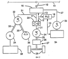
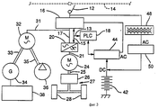
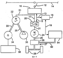
На фиг.1 изображен электромобиль горной промышленности, соответствующий изобретению в перспективе; на фиг.2 схема предпочтительной системы привода и энергоснабжения транспортного средства, использующей дизельный двигатель для выработки электрической энергии как вспомогательный источник энергии; на фиг.3 схема альтернативной системы энергоснабжения и привода электромобиля с батареей постоянного тока в качестве вспомогательного источника энергии; на фиг. 4 схема альтернативной системы энергоснабжения и привода транспортного средства, использующей дизельный двигатель для снабжения механической энергией непосредственно приводной цепи. Figure 1 shows an electric vehicle of the mining industry, corresponding to the invention in perspective; figure 2 diagram of a preferred drive system and power supply of a vehicle using a diesel engine to generate electrical energy as an auxiliary energy source; figure 3 diagram of an alternative power supply system and drive an electric vehicle with a DC battery as an auxiliary energy source; in FIG. 4 is a diagram of an alternative power supply and drive system of a vehicle using a diesel engine to supply mechanical power directly to the drive circuit.
Фиг. 1 показывает пригодный для подземного использования электромобиль горной промышленности 10. Стрела шарнирного пантографа 12 направлена вверх от электромобиля, действуя как энергетический канал, для создания электрического контакта с электропроводной подвесной контактной сетью 14. Контактная сеть 14 имеет криволинейную траекторию, определяющую путь транспортного средства. Сеть несет энергию переменного тока или 50, или 60 Гц от отдаленного источника (не показан) и включает четыре провода: три, обеспечивающие трехфазную энергию переменного тока, и один, соединенный с землей. Каждый из этих проводов электрически контактирует со стрелой пантографа 12. FIG. 1 shows an underground electric vehicle of the mining industry 10. The boom of the articulated
Фиг.2 схематически показывает предпочтительное воплощение системы привода электромобиля. Переключатель передачи 16 выборочно принимает энергию переменного тока со стрелы пантографа 12 и с альтернативных бортовых вспомогательных источников, которые будут обсуждены ниже. Переключатель 16 направляет энергию переменного тока к различным функциональным узлам транспортного средства. Программируемый логический контроллер (PLC) 18 автоматически управляет переключателем передачи 16 в зависимости от условий работы электромобиля или действий главного оператора. Когда между контактной сетью 14 и стрелой пантографа 12 создано необходимое соединение, PLC 18 разрешает оператору активизировать главную систему привода. Figure 2 schematically shows a preferred embodiment of an electric vehicle drive system. The
Главная система привода электромобиля включает имеющийся в продаже контроллер скорости электродвигателя переменного тока с широтно-импульсной модуляцией (PWM) 20, который изменяет частоту переменного тока на своем выходе. Выход контроллера контролируется PLC 18, который принимает его сигнал от ножной педали оператора (не показано). Контроллер двигателя 20 предпочтительно заключен в пыленепроницаемый защитный кожух (не показан) для предотвращения запыления и повреждения элементов, вызывающих нарушения его функций, хотя известный контроллер для электродвигателя переменного тока является большим и громоздким, его можно сделать более компактным при использовании альтернативной охлаждающей системы взамен известной системы воздушного охлаждения. Для применения с целью управления электромобилем контроллер двигателя должен быть противоударно закреплен на транспортном средстве для предотвращения повреждений от вибраций. The main electric vehicle drive system includes a commercially available pulse width modulated (PWM) 20 AC motor speed controller that changes the frequency of the alternating current at its output. The controller output is controlled by
Главный приводной двигатель переменного тока с регулируемой скоростью 24 соединен с выходом переменного тока контроллера двигателя 20 и передает энергию от выходного вала 25 коробки передач 26 механической трансмиссии 27 к ряду сцепляющихся с грунтом колес 28 для продвижения электромобиля. Если двигатель непосредственно связан с колесами, скорость транспортного средства прямо пропорциональна скорости двигателя. Для обычных тяговых применений подземных электромобилей горной промышленности приводной двигатель 24 следует устанавливать примерно на 800 лошадиных сил, хотя это может оказаться излишним с учетом конкретного применения тяговых свойств и размеров транспортного средства. В качестве альтернативы единственному приводному двигателю переменного тока, соединенному с механической трансмиссией, ряд отдельных колесных двигателей переменного тока с регулируемой скоростью (не показаны) может быть электрически соединен с контроллером двигателя 20 для отдельного привода каждого колеса 28. В таком воплощении выход каждого двигателя напрямую соединен с соответствующим колесом. Этот подход предназначается для электромобиля высокой мощности, так как четыре двигателя средней мощности могут быть энергетически более эффективными, чем один очень большой двигатель. Использование нескольких колесных двигателей также упраздняет необходимость в механической трансмиссии 27, включая коробку передач 26. The adjustable-speed main
В соответствии с другими альтернативными воплощениями (не показаны) может быть использован отдельный приводной двигатель переменного тока с регулируемой скоростью, вместо единственного двигателя 24, для привода каждой оси электромобиля. In accordance with other alternative embodiments (not shown), a separate variable-speed AC drive motor may be used, instead of a
Переключатель передачи 16 также через линию 31 обеспечивает энергией переменного тока дополнительный трехфазный электродвигатель переменного тока 32, который работает на постоянной скорости и механически соединен через приводные связи 33, 35, соответственно, для привода 24-вольтового генератора постоянного тока 34 и гидравлического насоса 36. Генератор 34 обеспечивает энергией постоянного тока электрическую систему постоянного тока электромобиля 38, в то время как гидравлический насос 36 создает давление в гидравлической системе транспортного средства, включая рулевое управление, механизм разгрузки и тормоза. The
Первичный двигатель, такой как дизельный двигатель 54, установленный на электромобиле 10, обеспечивает вспомогательный или резервный источник энергии для движения автомобиля транспортного средства, когда стрела пантографа 12 отсоединена от контактной сети или когда первичная энергия иным образом недоступна. Эта особенность позволяет электромобилю переключаться с одной контактной сети на другую на своей собственной энергии и маневрировать, когда не существует контактной сети. Мощность вспомогательной системы привода не является существенной, так как при отсоединении от контактной сети 14 электромобилю нужно двигаться только на низкой скорости. Дизельный двигатель 54 приводит в движение трехфазный генератор переменного тока 56, который электрически подсоединен так, чтобы обеспечить энергией переменного тока переключатель передачи 16. Последний обеспечивает энергией переменного тока через провод 17 контроллер двигателя 20, через провод 21 двигатель привода 24 для приведения в движение транспортного средства, а через провод 31 - дополнительный двигатель переменного тока 32 для питания энергией гидравлической системы и электрической системы постоянного тока 36, 38. A primary engine, such as a
Когда требуется вспомогательная энергия, сигнал оператора передается через программируемый логический контроллер 18, который запускает дизельный двигатель 54. Как только запускается двигатель, включается генератор 56, и резервная мощность доступна. PLC 18 затем координирует отсоединение от контактной сети 14 и подключение вспомогательной энергии в контроллер двигателя 20 и дополнительный двигатель 32. Управляющий сигнал между PLC и дизельным двигателем передается по линии 19. Управляющий сигнал между PLC и PWM и переключателем передачи передается по линиям 13 и 15. Переключение энергии делается без прерывания работы электромобиля, за исключением уменьшения его скорости, обусловленной ограничением имеющейся мощности от бортового источника, для переключения на контактную сеть 14 с вспомогательного источника энергии следует подобная же процедура, причем контроллер 18 управляет и непрерывно контролирует все требуемые функции. В альтернативном воплощении (фиг.3) электрическая аккумуляторная батарея 42, установленная на электромобиле, обеспечивает резервную энергию. Батарея 42 электрически соединена с инвертором 44, который преобразует постоянный ток в переменный ток. Инвертор 44 обеспечивает энергией переменного тока переключатель передачи 16, который направляет энергию в главную систему привода электромобиля и в дополнительный электродвигатель 32. Функционирование инвертора 44 контролируется программируемым логическим контроллером 18. Батарея 42 поддерживается заряженной трансформатором 48 и зарядным устройством 50, которые предусмотрены для получения энергии переменного тока со стрелы пантографа 12 и преобразования ее в энергию постоянного тока для зарядки батареи 42. В непоказанном альтернативном воплощении батарея может быть соединена с приводным двигателем постоянного тока, который посредством силовой механической трансмиссии соединен с коробкой передач 26. Транспортное средство таким образом может двигаться, когда стрела пантографа отсоединена, и исключена необходимость в инверторе 44, хотя потребуется отдельный контроллер скорости для электродвигателя постоянного тока. When auxiliary power is required, the operator signal is transmitted through a
В альтернативном воплощении, показанном на фиг. 4, выход дизельного двигателя 54 может быть соединен через вторичную механическую трансмиссию 60 с коробкой передач 26 для питания энергией электромобиля, когда стрела пантографа 12 отсоединена от контактной сети 14 или когда главный источник электрической энергии переменного тока недоступен по другой причине. In the alternative embodiment shown in FIG. 4, the output of the
В примерном предпочтительном воплощении электромобиль горной промышленности может использовать главный двигатель переменного тока 24 с установленной мощностью 560 кВт или свыше 800 лошадиных сил. Контроллер двигателя 20, сконструированный на заказ, приспособлен к горным условиям и имеет ранее описанные особенности. Подходящий электрический эквивалент должен быть спроектирован на 1400 A. Подходящий программируемый логический контроллер 18 выполняется с несколькими дискретными и аналоговыми входами и выходами, вспомогательный дизельный двигатель 54 сочленен с генератором 56. In an exemplary preferred embodiment, the mining electric vehicle may use an AC
Хотя все рабочие операции горной промышленности изменяются, следующее описание представляет типовой рабочий цикл для электромобиля предпочтительного воплощения. Although all mining operations vary, the following description represents a typical duty cycle for an electric vehicle of the preferred embodiment.
Когда транспортное средство не используется, оно паркуется на площадке технического обслуживания или в подземном цехе. Электромобиль приводится в службу сервиса на вспомогательной энергии, обеспечивающей подъезд к контактной сети, обычно за двухминутный пробег. Стрела пантографа сцепляется с контактной сетью и электромобиль едет на внешнем энергоснабжении вниз к зоне загрузки от нескольких сотен до нескольких тысяч метров, при пробеге от 20 до 30 мин. Зона загрузки обычно отсоединена от главной энергетической линии для предотвращения неполадок в линии во время загрузки и угрозы потери электробезопасности. When the vehicle is not in use, it parks at the maintenance site or in the underground workshop. The electric car is brought into the auxiliary energy service, providing access to the contact network, usually for a two-minute run. The arm of the pantograph interlocks with the contact network and the electric car travels on an external power supply down to the loading zone from several hundred to several thousand meters, with a run of 20 to 30 minutes. The loading area is usually disconnected from the main power line to prevent line malfunctions during loading and the risk of electrical loss.
Транспортное средство затем медленно движется на своей вспомогательной энергии в зону загрузки и загружается. Загрузка обычно занимает около двух минут. Сразу же после загрузки электромобиль возвращается обратно к контактной сети, зацепляется и едет, сколько возможно, к зоне разгрузки, обычно при 30-минутном пробеге. Затем он отцепляется от контактной сети и движется к зоне разгрузки на вспомогательной энергии, разгрузка занимает около пяти минут, после чего электромобиль возвращается обратно к контактной сети, зацепляется и повторяет цикл. The vehicle then slowly moves on its auxiliary energy into the loading zone and loads. Download usually takes about two minutes. Immediately after loading, the electric car returns to the contact network, hooks and travels as far as possible to the unloading zone, usually with a 30-minute run. Then it detaches from the contact network and moves to the unloading zone for auxiliary energy, unloading takes about five minutes, after which the electric car returns to the contact network, hooks and repeats the cycle.
В конце смены электромобиль возвращается к точке на контактной сети, ближайшей к зоне обслуживания, отцепляется и движется к месту парковки в зоне обслуживания. At the end of the shift, the electric car returns to the point on the contact network closest to the service area, detaches and moves to the parking place in the service area.
Claims (20)
Applications Claiming Priority (4)
| Application Number | Priority Date | Filing Date | Title |
|---|---|---|---|
| US753,719 | 1991-09-03 | ||
| US07/753,719 US5293947A (en) | 1991-09-03 | 1991-09-03 | Variable speed AC electric drive vehicle |
| US753719 | 1991-09-03 | ||
| PCT/US1992/007443 WO1993004887A1 (en) | 1991-09-03 | 1992-09-03 | Variable speed ac electric drive vehicle |
Publications (2)
| Publication Number | Publication Date |
|---|---|
| RU94018703A RU94018703A (en) | 1996-11-27 |
| RU2100221C1 true RU2100221C1 (en) | 1997-12-27 |
Family
ID=25031845
Family Applications (1)
| Application Number | Title | Priority Date | Filing Date |
|---|---|---|---|
| RU9494018703A RU2100221C1 (en) | 1991-09-03 | 1992-09-03 | Vehicle |
Country Status (10)
| Country | Link |
|---|---|
| US (1) | US5293947A (en) |
| EP (1) | EP0602186A1 (en) |
| JP (1) | JPH06510418A (en) |
| CN (1) | CN1085169A (en) |
| AU (1) | AU662355B2 (en) |
| CA (1) | CA2116585C (en) |
| FI (1) | FI941000A0 (en) |
| PL (1) | PL169771B1 (en) |
| RU (1) | RU2100221C1 (en) |
| WO (1) | WO1993004887A1 (en) |
Cited By (6)
| Publication number | Priority date | Publication date | Assignee | Title |
|---|---|---|---|---|
| US7963353B2 (en) | 2005-10-13 | 2011-06-21 | Toyota Jidosha Kabushiki Kaisha | Power output device of hybrid vehicle |
| RU2428328C1 (en) * | 2007-09-10 | 2011-09-10 | Тойота Дзидося Кабусики Кайся | Device and method to activate transport facility system |
| US8345453B2 (en) | 2007-09-21 | 2013-01-01 | Mitsubishi Electric Corporation | Power conversion apparatus for electric vehicle |
| RU2509664C1 (en) * | 2009-12-28 | 2014-03-20 | Сандвик Майнинг Энд Констракшн Ой | Mining vehicle and method of its power supply |
| US8714286B2 (en) | 2009-12-28 | 2014-05-06 | Sandvik Mining And Construction Oy | Mining vehicle and method for its energy supply |
| RU2543532C2 (en) * | 2013-05-13 | 2015-03-10 | Общество с ограниченной ответственностью "Научно-производственная фирма Ирбис" | Vehicle with independent drive |
Families Citing this family (77)
| Publication number | Priority date | Publication date | Assignee | Title |
|---|---|---|---|---|
| DE9419568U1 (en) * | 1994-12-07 | 1995-03-16 | Rosenau Viktor Dipl Ing Fh | Floor conveyor system with energy storage vehicles |
| DE29607651U1 (en) * | 1996-04-26 | 1997-08-28 | Kaessbohrer Gelaendefahrzeug G | Tracked vehicle |
| FR2783768B1 (en) * | 1998-09-28 | 2000-11-24 | Renault | CONTROL METHOD FOR A HYBRID VEHICLE WITH SERIAL ELECTRIC TRANSMISSION |
| CA2355670C (en) * | 1998-12-21 | 2004-10-26 | Siemens Energy & Automation, Inc. | System, method and apparatus for connecting electrical sources in series under full load |
| FR2799701A1 (en) * | 1999-10-19 | 2001-04-20 | Giovanni Tonarelli | Motorway lane, with overhead electrification to power hybrid trucks and buses, uses railway-style overhead electric lines with pantographs fitted to heavy vehicles that have a supplementary electric drive |
| PE20010833A1 (en) * | 1999-12-20 | 2001-09-08 | Siemens Energy And Automation Inc | SYSTEM, PROCEDURE AND APPARATUS FOR CONNECTING ELECTRICAL SOURCES IN SERIES UNDER FULL LOAD |
| AT500328B1 (en) | 2002-02-07 | 2010-03-15 | Elin Ebg Traction Gmbh | VEHICLE WITH AN ELECTRIC DRIVE AND METHOD FOR OPERATING SUCH A VEHICLE |
| CA2592250C (en) * | 2005-05-26 | 2012-08-21 | Mitsubishi Denki Kabushiki Kaisha | Controller for variable speed alternating current motor |
| US20080021602A1 (en) * | 2006-05-24 | 2008-01-24 | Ise Corporation | Electrically Powered Rail Propulsion Vehicle and Method |
| ES2454620T3 (en) * | 2006-09-18 | 2014-04-11 | Shanghai E-port Electric Co., Ltd. | Power supply equipment from an electrical supply network for cranes on tires in ports |
| FI125622B (en) * | 2008-06-13 | 2015-12-31 | Cargotec Finland Oy | Drive system for a forklift truck, terminal tractor or equivalent |
| US8360184B2 (en) * | 2008-07-06 | 2013-01-29 | Paul H. Kydd | Control system for electric hybrid vehicle conversion |
| US20100039054A1 (en) * | 2008-08-14 | 2010-02-18 | General Electric Company | Vehicle, system and method |
| FI121769B (en) * | 2008-11-26 | 2011-03-31 | Sandvik Mining & Constr Oy | A method of operating a mine vehicle, an arrangement at a mine, and a rock drilling machine |
| FR2949098A1 (en) * | 2009-08-13 | 2011-02-18 | Roger Norbert Margreve | Double electric power absorbing system for permanent supply of power to e.g. electric traction/propulsion motor of car, has road electric power absorbing device mounted under road vehicle to assure contact with bar integrated to road |
| KR101197317B1 (en) * | 2009-10-16 | 2012-11-05 | 한국과학기술원 | Device and method for dynamic configuration of electric power path in electric vehicle |
| KR101175358B1 (en) * | 2009-10-16 | 2012-08-20 | 한국과학기술원 | Power supply system for non contact electromagnetic inductive charging of Electric Vehicle |
| US8499909B2 (en) * | 2009-10-23 | 2013-08-06 | Siemens Industry, Inc. | Peak demand reduction in mining haul trucks utilizing an on-board energy storage system |
| EP2495146A1 (en) | 2009-10-27 | 2012-09-05 | Hitachi Construction Machinery Co., Ltd. | Electric drive vehicle |
| US8583303B2 (en) * | 2010-03-04 | 2013-11-12 | General Electric Company | Electric drive vehicle, system and method |
| US8950526B2 (en) * | 2010-11-02 | 2015-02-10 | Transport Energy Systems Pty Ltd | AC drive system for a vehicle |
| JP5767852B2 (en) * | 2011-05-10 | 2015-08-19 | 株式会社小松製作所 | Transport vehicle with current collector |
| JP5767851B2 (en) * | 2011-05-10 | 2015-08-19 | 株式会社小松製作所 | Transport vehicle with current collector |
| CN102381202A (en) * | 2011-08-17 | 2012-03-21 | 中国北车股份有限公司大连电力牵引研发中心 | Urban rail vehicle power supply system and urban rail vehicle |
| US9580966B2 (en) * | 2011-08-24 | 2017-02-28 | Lake Shore Systems, Inc. | All electric powered mobile jumbo drill machine |
| US20130126251A1 (en) * | 2011-11-18 | 2013-05-23 | Caterpillar, Inc. | Power System Control Strategy For Mining Truck |
| US8505464B2 (en) | 2011-12-01 | 2013-08-13 | Caterpillar Inc. | Control strategy for providing regenerative electrical power to trolley line in trolley capable mining truck |
| US20130140100A1 (en) * | 2011-12-01 | 2013-06-06 | Caterpillar Inc. | Control Strategy For Powering Auxiliary Device In Trolley Capable Mining Truck |
| US8857542B2 (en) * | 2011-12-08 | 2014-10-14 | Caterpillar Inc. | Method and apparatus to eliminate fuel use for electric drive machines during trolley operation |
| US9170081B2 (en) * | 2012-02-23 | 2015-10-27 | Oldenburg Group Incorporated | All-electric powered ANFO vehicle |
| DE102012202955A1 (en) * | 2012-02-27 | 2013-08-29 | Schunk Bahn- Und Industrietechnik Gmbh | Power transmission device for charging electrical energy storage of vehicles at overhead charging stations |
| US9637005B2 (en) * | 2012-03-30 | 2017-05-02 | Caterpillar Inc. | Display conveying trolley position to operator |
| US8838320B2 (en) * | 2012-03-30 | 2014-09-16 | Caterpillar Inc. | Laser sensors for trolley guidance signal |
| US20130264163A1 (en) * | 2012-04-10 | 2013-10-10 | Caterpillar Inc. | Pantograph mounting structure |
| US8818593B2 (en) | 2012-04-22 | 2014-08-26 | Caterpillar Inc. | Trolley driven machine record and playback automation |
| SE542381C2 (en) | 2012-04-23 | 2020-04-21 | Brokk Ab | Electrically powered demolition robot and its power supply system |
| JP5839697B2 (en) * | 2012-04-26 | 2016-01-06 | 日立建機株式会社 | Operation management system |
| US8874294B2 (en) | 2012-06-04 | 2014-10-28 | Caterpillar Inc. | Simplified topology for trolley assist-capable electric drive truck |
| US11449018B2 (en) | 2012-11-16 | 2022-09-20 | U.S. Well Services, LLC | System and method for parallel power and blackout protection for electric powered hydraulic fracturing |
| US9745840B2 (en) | 2012-11-16 | 2017-08-29 | Us Well Services Llc | Electric powered pump down |
| US11476781B2 (en) | 2012-11-16 | 2022-10-18 | U.S. Well Services, LLC | Wireline power supply during electric powered fracturing operations |
| US9893500B2 (en) | 2012-11-16 | 2018-02-13 | U.S. Well Services, LLC | Switchgear load sharing for oil field equipment |
| US9995218B2 (en) | 2012-11-16 | 2018-06-12 | U.S. Well Services, LLC | Turbine chilling for oil field power generation |
| US10232332B2 (en) | 2012-11-16 | 2019-03-19 | U.S. Well Services, Inc. | Independent control of auger and hopper assembly in electric blender system |
| US10407990B2 (en) | 2012-11-16 | 2019-09-10 | U.S. Well Services, LLC | Slide out pump stand for hydraulic fracturing equipment |
| EP2738035A1 (en) * | 2012-11-28 | 2014-06-04 | Sandvik Mining and Construction Oy | A method and an arrangement for controlling power supply in an electric mining unit, and a method for controlling power supply in a mining unit, as well as a mining unit |
| SE536908C2 (en) | 2013-01-18 | 2014-10-28 | Enega AB | Device for providing electric drive of heavy vehicles |
| EP2789519B1 (en) * | 2013-04-12 | 2016-12-28 | System7-Railsupport GmbH | Device for transporting material in rail construction |
| EP2810809A1 (en) * | 2013-06-07 | 2014-12-10 | Sandvik Mining and Construction Oy | Mining vehicle and method for its energy supply |
| CN104340568A (en) * | 2013-07-25 | 2015-02-11 | 芜湖爱瑞特环保科技有限公司 | Heavy-load garbage truck with AC (alternate current) controller |
| EP3030440B1 (en) * | 2013-08-06 | 2019-04-24 | Volvo Truck Corporation | Hybrid vehicle |
| US9969283B2 (en) | 2013-09-10 | 2018-05-15 | General Electric Company | Battery changing system and method |
| US10286787B2 (en) * | 2013-09-27 | 2019-05-14 | Siemens Industry, Inc. | System and method for all electrical operation of a mining haul truck |
| JP6321935B2 (en) * | 2013-09-30 | 2018-05-09 | 株式会社小松製作所 | Mining system |
| EP2857253B1 (en) | 2013-10-02 | 2016-05-11 | Sandvik Mining and Construction Oy | Mining vehicle and method for its energy supply |
| CN103863103B (en) * | 2014-02-26 | 2017-01-04 | 北京科技大学 | A kind of have double dynamical electric transmission underground mining truck |
| CA2865638C (en) | 2014-03-26 | 2021-01-26 | Robert Brydon Thomas Owen | Controlling batteries for electric bus |
| CN104210385B (en) * | 2014-08-19 | 2016-09-07 | 吉林大学 | The omnidistance electric railway network system without negative phase-sequence interval unpowered net |
| US10377251B2 (en) | 2015-03-26 | 2019-08-13 | Proterra Inc. | Electric vehicle charging interface |
| US9321364B1 (en) | 2015-06-30 | 2016-04-26 | Proterra Inc. | Heated charging interface of electric vehicle |
| EP3184349A1 (en) * | 2015-12-22 | 2017-06-28 | Siemens Aktiengesellschaft | Energy supply system for vehicle and vehicle with electric traction system |
| CN105751845B (en) * | 2016-04-08 | 2018-11-09 | 江苏大学 | A kind of semi-active control method of energy feeding back type semi-active suspension system |
| US9994117B2 (en) | 2016-04-20 | 2018-06-12 | Artisan Vehicle Systems Inc. | System and method for providing power to a mining operation |
| FI20165891L (en) * | 2016-11-24 | 2018-05-25 | Normet Oy | Method and arrangement for actuating power pack |
| EP3558744B1 (en) * | 2016-12-22 | 2021-10-13 | ABB Schweiz AG | Hybrid drive system for a traction vehicle |
| ES2677073B1 (en) * | 2017-01-27 | 2019-05-07 | Serrat Salvador Ayats | Land vehicle |
| CA3084607A1 (en) | 2017-12-05 | 2019-06-13 | U.S. Well Services, LLC | High horsepower pumping configuration for an electric hydraulic fracturing system |
| US10648270B2 (en) | 2018-09-14 | 2020-05-12 | U.S. Well Services, LLC | Riser assist for wellsites |
| GB2578484A (en) * | 2018-10-29 | 2020-05-13 | Mastenbroek Ltd | Trenching apparatus and a method of trenching |
| EP3894261A1 (en) * | 2018-12-14 | 2021-10-20 | Volvo Truck Corporation | An electric power transmission system for a vehicle |
| US11578577B2 (en) | 2019-03-20 | 2023-02-14 | U.S. Well Services, LLC | Oversized switchgear trailer for electric hydraulic fracturing |
| PE20212126A1 (en) | 2019-04-03 | 2021-11-05 | Artisan Vehicle Systems Inc | INTERCHANGEABLE ENERGY DEVICE FOR ELECTRIC VEHICLE |
| CA3139970A1 (en) | 2019-05-13 | 2020-11-19 | U.S. Well Services, LLC | Encoderless vector control for vfd in hydraulic fracturing applications |
| US11506126B2 (en) | 2019-06-10 | 2022-11-22 | U.S. Well Services, LLC | Integrated fuel gas heater for mobile fuel conditioning equipment |
| US11459863B2 (en) | 2019-10-03 | 2022-10-04 | U.S. Well Services, LLC | Electric powered hydraulic fracturing pump system with single electric powered multi-plunger fracturing pump |
| CA3211298A1 (en) * | 2021-08-05 | 2023-02-09 | Yoichi Iihoshi | Mine management system |
| WO2024010498A1 (en) * | 2022-07-04 | 2024-01-11 | Epiroc Rock Drills Aktiebolag | Dynamic power allocation for mining machines |
Family Cites Families (19)
| Publication number | Priority date | Publication date | Assignee | Title |
|---|---|---|---|---|
| US2210675A (en) * | 1936-09-18 | 1940-08-06 | Westinghouse Electric & Mfg Co | Multipower driving vehicle |
| US3547237A (en) * | 1968-06-13 | 1970-12-15 | Kenneth H Ives | Remotely controlled power pickup for trackless electric vehicles |
| JPS4930648B1 (en) * | 1969-12-12 | 1974-08-15 | ||
| US3704760A (en) * | 1971-06-22 | 1972-12-05 | Oscar Kogyo Kk | Electropneumatic propelling system for vehicles |
| US3791881A (en) * | 1972-03-02 | 1974-02-12 | Us Navy | Annealing treatment for controlling warhead fragmentation size distribution |
| FR2316110A1 (en) * | 1975-07-02 | 1977-01-28 | Cem Oerlikon Traction | Traction control for trolley bus - having standby engine driving motor generator supply is disconnected |
| SE402246B (en) * | 1976-10-21 | 1978-06-26 | Krongard Sven Olof | VEHICLE OR MOBILE WORKING MACHINE |
| US4099589A (en) * | 1976-12-20 | 1978-07-11 | Trans Research Development Corporation | DC electric car with auxiliary power and AC drive motor |
| DE2943519A1 (en) * | 1979-10-27 | 1981-05-07 | Volkswagenwerk Ag | DRIVE FOR A VEHICLE WITH AN INTERNAL COMBUSTION ENGINE AND AN ELECTRIC MOTOR |
| EP0073861A1 (en) * | 1981-09-04 | 1983-03-16 | Alexander Mencher Corporation | Hybrid propulsion apparatus and method |
| JPS58179803U (en) * | 1982-05-27 | 1983-12-01 | 株式会社小松製作所 | Vehicle speed control device for single-phase AC type trolley-assisted dump truck |
| DE3235337A1 (en) * | 1982-09-24 | 1984-03-29 | Krauss-Maffei AG, 8000 München | Method and circuit arrangement for radio controlling an electrical rail power unit equipped with an additional diesel-driven generator |
| JPS62104403A (en) * | 1985-10-29 | 1987-05-14 | Isuzu Motors Ltd | Driving device for vehicle |
| JPH0623121Y2 (en) * | 1986-08-05 | 1994-06-15 | 昌煕 金 | Electric drive propulsion device for automobile |
| US4809803A (en) * | 1987-04-06 | 1989-03-07 | General Dynamics-Land Systems | Drive system and vehicle for use therewith |
| US4807803A (en) * | 1987-04-15 | 1989-02-28 | Ulike Corporation | Packing structure for collapsible basket holder |
| JPH01295605A (en) * | 1988-05-24 | 1989-11-29 | Toshiba Corp | Emergency travel power source for trolley bus |
| IT1228713B (en) * | 1989-03-10 | 1991-07-03 | Socimi | ELECTRIC TRACTION EQUIPMENT, IN PARTICULAR FOR PUBLIC TRANSPORT VEHICLES. |
| US5103923A (en) * | 1989-11-30 | 1992-04-14 | Marathon Letourneau Company | Method and apparatus for propelling and retarding off-road haulers |
-
1991
- 1991-09-03 US US07/753,719 patent/US5293947A/en not_active Expired - Fee Related
-
1992
- 1992-09-03 PL PL92302614A patent/PL169771B1/en unknown
- 1992-09-03 RU RU9494018703A patent/RU2100221C1/en active
- 1992-09-03 EP EP92920661A patent/EP0602186A1/en not_active Ceased
- 1992-09-03 WO PCT/US1992/007443 patent/WO1993004887A1/en not_active Application Discontinuation
- 1992-09-03 AU AU26539/92A patent/AU662355B2/en not_active Ceased
- 1992-09-03 JP JP5505396A patent/JPH06510418A/en active Pending
- 1992-09-03 CA CA002116585A patent/CA2116585C/en not_active Expired - Fee Related
- 1992-09-30 CN CN92112485A patent/CN1085169A/en active Pending
-
1994
- 1994-03-02 FI FI941000A patent/FI941000A0/en not_active Application Discontinuation
Non-Patent Citations (1)
| Title |
|---|
| DE, заявка, 2629840, кл. B 60 L 9/00, 1979. * |
Cited By (9)
| Publication number | Priority date | Publication date | Assignee | Title |
|---|---|---|---|---|
| US7963353B2 (en) | 2005-10-13 | 2011-06-21 | Toyota Jidosha Kabushiki Kaisha | Power output device of hybrid vehicle |
| RU2428328C1 (en) * | 2007-09-10 | 2011-09-10 | Тойота Дзидося Кабусики Кайся | Device and method to activate transport facility system |
| US8301322B2 (en) | 2007-09-10 | 2012-10-30 | Toyota Jidosha Kabushiki Kaisha | Apparatus and method for activating system of vehicle |
| US8345453B2 (en) | 2007-09-21 | 2013-01-01 | Mitsubishi Electric Corporation | Power conversion apparatus for electric vehicle |
| RU2509664C1 (en) * | 2009-12-28 | 2014-03-20 | Сандвик Майнинг Энд Констракшн Ой | Mining vehicle and method of its power supply |
| US8714286B2 (en) | 2009-12-28 | 2014-05-06 | Sandvik Mining And Construction Oy | Mining vehicle and method for its energy supply |
| RU2514867C2 (en) * | 2009-12-28 | 2014-05-10 | Сандвик Майнинг Энд Констракшн Ой | Mining vehicle and method of its power supply |
| US8955657B2 (en) | 2009-12-28 | 2015-02-17 | Sandvik Mining And Construction Oy | Mining vehicle and method for its energy supply |
| RU2543532C2 (en) * | 2013-05-13 | 2015-03-10 | Общество с ограниченной ответственностью "Научно-производственная фирма Ирбис" | Vehicle with independent drive |
Also Published As
| Publication number | Publication date |
|---|---|
| CN1085169A (en) | 1994-04-13 |
| CA2116585C (en) | 1996-08-06 |
| AU662355B2 (en) | 1995-08-31 |
| RU94018703A (en) | 1996-11-27 |
| EP0602186A4 (en) | 1994-08-31 |
| FI941000A (en) | 1994-03-02 |
| US5293947A (en) | 1994-03-15 |
| WO1993004887A1 (en) | 1993-03-18 |
| AU2653992A (en) | 1993-04-05 |
| PL169771B1 (en) | 1996-08-30 |
| FI941000A0 (en) | 1994-03-02 |
| EP0602186A1 (en) | 1994-06-22 |
| CA2116585A1 (en) | 1993-03-18 |
| JPH06510418A (en) | 1994-11-17 |
Similar Documents
| Publication | Publication Date | Title |
|---|---|---|
| RU2100221C1 (en) | Vehicle | |
| EP1229636B1 (en) | A/C bus assembly for electric traction vehicle | |
| US7848857B2 (en) | System and method for braking in an electric vehicle | |
| US7521814B2 (en) | System and method for providing low voltage 3-phase power in a vehicle | |
| US4495451A (en) | Inertial energy interchange system with energy makeup by combustion engine on demand | |
| US4900944A (en) | Booster unit for diesel electric locomotive | |
| NO180436B (en) | Electric drive and distribution system for a vehicle, as well as a method for operating such a system | |
| CN103660950B (en) | System and method for producing power in vehicle | |
| CN111114306A (en) | Construction machine | |
| WO1979001127A1 (en) | Battery propelled vehicles | |
| CN101214831B (en) | Bidirectional mine transport vehicle | |
| CN110315995A (en) | Three-in-one controller for electric vehicle | |
| JPS6160641B2 (en) | ||
| JPS6112442B2 (en) | ||
| JPS6277804A (en) | Trolley bus driving device | |
| RU2116205C1 (en) | Vehicle | |
| KR20230050419A (en) | Electric drive for mixer drum | |
| GB2101813A (en) | Friction wheel driven generators for electric and other vehicles | |
| JP2015039919A (en) | Work vehicle | |
| CN109532443A (en) | A kind of electric LHD | |
| JPH05176411A (en) | Driver for electric automobile | |
| WO2018013036A1 (en) | Vehicle with ac outlet | |
| JP2000335498A (en) | Electric power feeding facility for aircraft | |
| HRP930418A2 (en) | Method and apparatus for propelling and retarding off - road haulers | |
| PL190082B1 (en) | Battery-powered overhead monorail tractive trolley |