RU2089986C1 - System for power take-off from high-voltage dc power transmission line - Google Patents
System for power take-off from high-voltage dc power transmission line Download PDFInfo
- Publication number
- RU2089986C1 RU2089986C1 SU905010490A SU5010490A RU2089986C1 RU 2089986 C1 RU2089986 C1 RU 2089986C1 SU 905010490 A SU905010490 A SU 905010490A SU 5010490 A SU5010490 A SU 5010490A RU 2089986 C1 RU2089986 C1 RU 2089986C1
- Authority
- RU
- Russia
- Prior art keywords
- voltage
- converter
- transformer
- current
- direct current
- Prior art date
Links
Images
Classifications
-
- H—ELECTRICITY
- H02—GENERATION; CONVERSION OR DISTRIBUTION OF ELECTRIC POWER
- H02M—APPARATUS FOR CONVERSION BETWEEN AC AND AC, BETWEEN AC AND DC, OR BETWEEN DC AND DC, AND FOR USE WITH MAINS OR SIMILAR POWER SUPPLY SYSTEMS; CONVERSION OF DC OR AC INPUT POWER INTO SURGE OUTPUT POWER; CONTROL OR REGULATION THEREOF
- H02M7/00—Conversion of ac power input into dc power output; Conversion of dc power input into ac power output
- H02M7/66—Conversion of ac power input into dc power output; Conversion of dc power input into ac power output with possibility of reversal
- H02M7/68—Conversion of ac power input into dc power output; Conversion of dc power input into ac power output with possibility of reversal by static converters
- H02M7/72—Conversion of ac power input into dc power output; Conversion of dc power input into ac power output with possibility of reversal by static converters using discharge tubes with control electrode or semiconductor devices with control electrode
- H02M7/75—Conversion of ac power input into dc power output; Conversion of dc power input into ac power output with possibility of reversal by static converters using discharge tubes with control electrode or semiconductor devices with control electrode using devices of a thyratron or thyristor type requiring extinguishing means
- H02M7/757—Conversion of ac power input into dc power output; Conversion of dc power input into ac power output with possibility of reversal by static converters using discharge tubes with control electrode or semiconductor devices with control electrode using devices of a thyratron or thyristor type requiring extinguishing means using semiconductor devices only
- H02M7/7575—Conversion of ac power input into dc power output; Conversion of dc power input into ac power output with possibility of reversal by static converters using discharge tubes with control electrode or semiconductor devices with control electrode using devices of a thyratron or thyristor type requiring extinguishing means using semiconductor devices only for high voltage direct transmission link
-
- H—ELECTRICITY
- H02—GENERATION; CONVERSION OR DISTRIBUTION OF ELECTRIC POWER
- H02J—CIRCUIT ARRANGEMENTS OR SYSTEMS FOR SUPPLYING OR DISTRIBUTING ELECTRIC POWER; SYSTEMS FOR STORING ELECTRIC ENERGY
- H02J3/00—Circuit arrangements for ac mains or ac distribution networks
- H02J3/36—Arrangements for transfer of electric power between ac networks via a high-tension dc link
-
- Y—GENERAL TAGGING OF NEW TECHNOLOGICAL DEVELOPMENTS; GENERAL TAGGING OF CROSS-SECTIONAL TECHNOLOGIES SPANNING OVER SEVERAL SECTIONS OF THE IPC; TECHNICAL SUBJECTS COVERED BY FORMER USPC CROSS-REFERENCE ART COLLECTIONS [XRACs] AND DIGESTS
- Y02—TECHNOLOGIES OR APPLICATIONS FOR MITIGATION OR ADAPTATION AGAINST CLIMATE CHANGE
- Y02E—REDUCTION OF GREENHOUSE GAS [GHG] EMISSIONS, RELATED TO ENERGY GENERATION, TRANSMISSION OR DISTRIBUTION
- Y02E60/00—Enabling technologies; Technologies with a potential or indirect contribution to GHG emissions mitigation
- Y02E60/60—Arrangements for transfer of electric power between AC networks or generators via a high voltage DC link [HVCD]
Abstract
Description
Передача на большие расстояния электроэнергии по высоковольтным линиям постоянного тока постепенно становится общепринятой, в частности, вследствие меньших на них затрат. Большие затраты в таких линиях приходятся на преобразователи тока при отборе и трансформаторах. Вследствие этого непрактично размещать вдоль такой высоковольтной линии несколько полностью укомплектованных принимающих станций. Long-distance transmission of electricity through high-voltage direct current lines is gradually becoming generally accepted, in particular due to lower costs. High costs in such lines are for current transformers for selection and transformers. Because of this, it is impractical to place several fully-equipped receiving stations along such a high-voltage line.
Для отбора меньших напряжений чем в линии, обычно это менее 10% было предложено, чтобы токоотборные станции подсоединялись последовательно в цепь постоянного тока и ток отбирался бы в соответствии с перепадом напряжения в линии. Самое простое решение этого типа предусматривает применение трехфазного преобразователя тока, подключенного последовательно в цепь постоянного тока. Этот шунт преобразователей подсоединяется напрямую к трехфазной сети через трансформатор. Шунт является коммутированным по линии, что означает что коммутация (эл. ) вентилей достигается с помощью тока переменного напряжения в трехфазной сети. To select lower voltages than in the line, usually less than 10%, it was suggested that the collector stations should be connected in series to the DC circuit and the current should be selected in accordance with the voltage drop in the line. The simplest solution of this type involves the use of a three-phase current converter connected in series to a DC circuit. This converter shunt is connected directly to a three-phase network via a transformer. The shunt is commutated along the line, which means that the switching of the (electronic) valves is achieved using an alternating voltage current in a three-phase network.
Первым недостатком систем такого типа является то, что коммутация по линии требует оборудования синхронизаторами, что становится экономически нерентабельным в случае устройства небольших и средних сетей. Вторым недостатком является то, что применение трансформатора дорого в сравнении с отбираемой энергией, а третий недостаток возмущения и помехи в сети переменного тока могут привести к таким же явлениям в коммутационном процессе в преобразователе тока, и таким образом, в основной сети. The first drawback of this type of system is that line switching requires equipment with synchronizers, which becomes economically unprofitable in the case of small and medium-sized networks. The second drawback is that the use of a transformer is expensive in comparison with the selected energy, and the third drawback of disturbances and interference in the AC network can lead to the same phenomena in the switching process in the current converter, and thus in the main network.
Одной из целей изобретения является создание серии систем для отбора электроэнергии, способной устранить эти недостатки. Другой целью является создание системы энергоотбора, которая позволила бы небольшим сетям получать небольшие напряжения (объемы энергии) экономически рентабельным способом. Таковая возможность обладает особенно большой ценностью для государственных (не частных) энергокомпаний, которым трудно рассчитывать на понимание в случае затруднений с подачей электроэнергии в малонаселенные регионы, по которым проходит дорогостоящая линия энергопередачи. One of the objectives of the invention is the creation of a series of systems for the selection of electricity that can eliminate these disadvantages. Another goal is to create an energy extraction system that would allow small networks to receive small voltages (energy volumes) in an economically viable way. Such an opportunity is especially valuable for state-owned (non-private) energy companies, which find it difficult to rely on understanding in the event of difficulties in supplying electricity to sparsely populated regions through which an expensive power transmission line passes.
Эти и другие цели достигаются по изобретению посредством системы, имеющей такие отличительные черты, как это указано в п. 1 формулы изобретения. These and other objectives are achieved according to the invention by means of a system having such distinctive features as indicated in paragraph 1 of the claims.
Изобретение позволяет отбирать небольшие количества энергии от больших сетей высоковольтных линий передачи постоянного тока с помощью относительно недорогих компонентов, так что стоимость подачи энергии оказывается экономически целесообразной. Все что нужно подсоединить к высоковольтной линии это преобразователь, преобразующий один ток в соответствующий другой ток, включенный по мостовой схеме с соответствующим коммутационным оборудованием, управляемый по волоконной оптике с земли и первичной обмотки трансформатора, причем нагрузкой на эту обмотку будет только перепад напряжения, соответствующий отобранной энергии. Для того, чтобы дать представление об идее (концепции), можно представить себе некий случай, в котором имеется высоковольтная линия передачи прямого тока известного типа с напряжением ±500 кВ и максимальной силой тока 1600 А. Первыми подсоединяются в эту сеть первый преобразователь и первичная обмотка трансформатора. Обои могут быть однофазными. Первичная обмотка должна выдерживать полностью ток в 1600 А и должна быть изолирована материалом, выдерживающим 500 кВ, от сердечника трансформатора. С другой стороны, нет необходимости давать на обмотку напряжение большее, чем соответствующее отобранной энергии, т.е. максимум 50 кВ при максимальной мощности 80 МВт. Стоимость использования трансформатора также может быть снижена, если полученному переменному току придать большую частоту, чем обычно это принято, т.е. частоту 120 150 Гц. Его потом снимают с вторичной обмотки трансформатора (40 кВ, 2 кА), который выпрямляется далее на ток постоянной местной сети на 40 кВ во втором преобразователе, который принимается как имеющий ускоренную коммутацию (переключение). Предпочтительно, чтобы трехфазный ток получался из этого тока постоянного напряжения путем преобразования в третьем преобразователе, каковой преобразователь может иметь ускоренную коммутацию на частоту тока в сети 50 или 60 Гц соответственно потребности, при напряжении, пригодном для местной передачи. The invention allows the selection of small amounts of energy from large networks of high voltage direct current transmission lines using relatively inexpensive components, so that the cost of power supply is economically feasible. All that needs to be connected to the high-voltage line is a converter that converts one current into a corresponding other current, connected via a bridge circuit with the appropriate switching equipment, controlled by fiber optics from the ground and the primary winding of the transformer, and the load on this winding will only be the voltage drop corresponding to the selected energy. In order to give an idea of an idea (concept), we can imagine a certain case in which there is a high-voltage direct current transmission line of a known type with a voltage of ± 500 kV and a maximum current of 1600 A. The first converter and primary winding are connected first to this network. transformer. Wallpaper can be single-phase. The primary winding must fully withstand a current of 1600 A and must be isolated by a material withstanding 500 kV from the core of the transformer. On the other hand, there is no need to give to the winding a voltage greater than the corresponding selected energy, i.e. 50 kV maximum with a maximum power of 80 MW. The cost of using a transformer can also be reduced if the received alternating current is given a higher frequency than is usually accepted, i.e. frequency 120 150 Hz. It is then removed from the secondary winding of the transformer (40 kV, 2 kA), which is then rectified to a current of a constant local network of 40 kV in a second converter, which is adopted as having accelerated switching (switching). Preferably, a three-phase current is obtained from this direct current voltage by conversion in a third converter, which converter can have accelerated switching to a current frequency of 50 or 60 Hz in the network, respectively, at a voltage suitable for local transmission.
Местная сеть энергопередачи в предпочтительном варианте поддерживает постоянное напряжение с помощью конденсатора и может быть оснащена также, дополнительно, аккумуляторной батареей для накопления и временного хранения энергии. Расход энергии предпочтительно контролировать по замеру напряжения в местной сети постоянного тока, которое имеет тенденцию падения при увеличивающемся расходе электроэнергии через третий преобразователь, и путем управления коммутацией (переключением) первого и второго преобразователей с целью получения требуемого напряжения постоянного тока в местной сети. The local power transmission network preferably maintains a constant voltage with a capacitor and can also be equipped with an additional battery for storing and temporarily storing energy. It is preferable to control the energy consumption by measuring the voltage in the local DC network, which tends to fall with increasing energy consumption through the third converter, and by controlling the switching (switching) of the first and second converters in order to obtain the required DC voltage in the local network.
Второй и третий преобразователи соответственно выполняются из полностью управляемых полупроводниковых вентилей (двухоперационные триодные, т.е. GTO-тиристоры), которые пропускают ток в обоих направлениях, в то время как первый преобразователь состоит из управляемых полупроводниковых вентилей с блокировкой от перемены полярности тока. Сети передачи электроэнергии будут тогда включать фильтрующие цепи, используемые для устранения пульсаций, возникающих при отборе тока. The second and third converters, respectively, are made up of fully controllable semiconductor gates (two-stage triode, i.e. GTO thyristors) that pass current in both directions, while the first transducer consists of controllable semiconductor valves that block current polarity. Electricity transmission networks will then include filter circuits used to eliminate ripple arising from current extraction.
Стоимость энергоотборных станций будет умеренной, особенно в связи с тем, что напряжение между гребешками коллекторов от линии высокого напряжения относительно низкое, позволяя тем самым даже использовать коллекторные гребешки в качестве преобразующего трансформатора между первым и вторым преобразователями через обычный фарфоровый изолятор. Используемое для иллюстрации исполнение в ряд его вариантов ниже будет описано со ссылками на приложенные чертежи. Для того, чтобы не усложнять описание подробностями известного уровня техники передачи постоянного тока высокого напряжения, делается ссылка на монографическую литературу в этой области, такую как Power Tranmission by Direct Current. Передача энергии постоянным током (Springer Verlag 1975). The cost of the energy extraction stations will be moderate, especially since the voltage between the collector combs from the high voltage line is relatively low, thereby even allowing the use of collector combs as a conversion transformer between the first and second converters through a conventional porcelain insulator. Used to illustrate the execution in a number of variants below will be described with reference to the attached drawings. In order not to complicate the description with details of the prior art for high voltage direct current transmission, reference is made to monographic literature in this area, such as Power Tranmission by Direct Current. DC power transmission (Springer Verlag 1975).
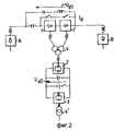
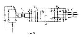
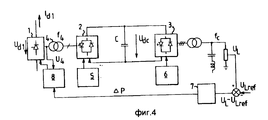
На фиг.1 изображена блок-схема предлагаемой системы; на фиг.2 и 3 более детальное изображение схемы; на фиг.4 блок-схема, иллюстрирующая исполнение системы управления описываемой системы отбора. Figure 1 shows a block diagram of the proposed system; figure 2 and 3 a more detailed image of the circuit; figure 4 is a block diagram illustrating the execution of the control system of the described selection system.
Блок-схема на фиг. 1 иллюстрирует принципиальное устройство с четырьмя отличающимися друг от друга по напряжению системами, а именно: линия передачи постоянного тока высокого напряжения, откуда отбирается часть энергии, в которой, например, 500 кВ, первая система с переменным током AC1, в которой, предпочтительно, частота тока в 2 4 раза выше стандартной, система с постоянным током ДС, например 40 кВ, и вторая система с переменным током AC2, в котором ток имеет частоту сети и которая предназначена передавать/создавать местную систему энергораспределения. Энергия передается между этими двумя системами посредством преобразователей, включенных по мостовой схеме. Хотя первая система с переменным током может быть однофазной, однако это может быть и трехфазная сеть, как проиллюстрировано на фиг.2. The block diagram of FIG. 1 illustrates a principle device with four different voltage systems, namely: a high voltage direct current transmission line, from which a part of the energy is taken, in which, for example, 500 kV, the first alternating current system AC1, in which, preferably, the frequency the current is 2 to 4 times higher than the standard one, a system with a direct current DC, for example 40 kV, and a second system with alternating current AC2, in which the current has a network frequency and which is designed to transmit / create a local power distribution system. Energy is transferred between the two systems through converters connected via a bridge circuit. Although the first AC system can be single-phase, it can also be a three-phase network, as illustrated in FIG.
В целях обеспечения широкого диапазона отбора энергии могло бы быть также целесообразно ввести на линии постоянного тока высокого напряжения некое множество активируемых и дезактивируемых преобразователей, причем функция каждого заключалась бы в передаче соответствующего переменного тока, мощность которых объединена, т.е. путем подачи указанных токов к соответствующей первичной обмотке в первом трансформаторе. Путем выбора соответствующего устройства было бы возможно таким путем избежать излишне больших углов возбуждения на выпрямляющих тиристорах и связанных с этим широко известных проблем. In order to ensure a wide range of energy selection, it might also be advisable to introduce some set of activated and deactivated converters on the high-voltage direct current lines, the function of each being to transmit the corresponding alternating current, the power of which is combined, i.e. by supplying the indicated currents to the corresponding primary winding in the first transformer. By selecting the appropriate device, it would be possible in this way to avoid unnecessarily large field angles on rectifying thyristors and the associated well-known problems.
Очевидно, что однофазная система будет самой дешевой, так как требуются только четыре тиристорных группы на высоковольтной стороне, причем эти тиристоры должны быть способны выдерживать только максимальный перепад напряжений высоковольтной линии в сравнении с принципиальной системой и иметь в системе одну обмотку, изолированную от высокого напряжения в трансформаторе 4. Это связано с выбором мощности (емкости), и в некоторых случаях, возможно, как показано на фиг.2, соединять несколько преобразователей 1, 1' последовательно, когда величина отбираемой энергии возрастет, и применять более дорогостоящую двенадцатиимпульсную коммутацию и т.д. в соответствии с превалирующими потребностями. Однако в случае отбора небольших и средних количеств энергии предпочтительно работать с однофазным напряжением частотой 120-150 Гц, так как трансформатор 4 может обойтись дешевле в этом случае. Частота также может быть регулируемой, так чтобы управлять процессом отбора энергии. Obviously, a single-phase system will be the cheapest, since only four thyristor groups are required on the high-voltage side, and these thyristors must be able to withstand only the maximum voltage drop of the high-voltage line in comparison with the principle system and have one winding isolated from high voltage in the system transformer 4. This is due to the choice of power (capacity), and in some cases, it is possible, as shown in figure 2, to connect several converters 1, 1 'in series, when the values It takes energy to grow and to use more expensive dvenadtsatiimpulsnuyu switching, etc. according to prevailing needs. However, in the case of selection of small and medium amounts of energy, it is preferable to work with a single-phase voltage with a frequency of 120-150 Hz, since transformer 4 can be cheaper in this case. The frequency may also be adjustable so as to control the energy extraction process.
Чертежи представляют в символах всю сеть, включая конечные станции A и B линии передачи постоянного тока высокого напряжения (ЛПТВК), а также систему отбора энергии, подсоединенную к одному из проводов линии, который может быть одним из двух жил (проводов) двухжильного провода (не показано). The drawings represent the entire network in symbols, including the terminal stations A and B of the high voltage direct current transmission line (LPTVK), as well as an energy extraction system connected to one of the wires of the line, which can be one of the two wires (wires) of a two-wire wire (not shown).
Система, показанная на фиг. 2 и 3, включает полупроводниковые вентили (преобразователей) 2 и 3, причем эти вентили запираются посредством колебания тока (тип GTO). Преобразователь 2, показанный на фиг.2, указан как поддерживающий постоянное напряжение и ускоренно коммутируемый. По крайней мере один из преобразователей 1 и 2 должен иметь ускоренную коммутацию. Преобразователь 2 тогда подсоединяется через переменный ток взаимодействия к преобразователю 3, который имеет ускоренную коммутацию и подключен напрямую в цепь переменного тока системы распределения (энергии). Так как работа идет при относительно постоянном напряжении постоянного тока, возможно использовать аккумуляторную батарею, что облегчит запуск системы при перерыве в питании сети переменного тока, а также избежать возмущений в питающей сети постоянного тока и наоборот. Если преобразователь 3 имеет ускоренную коммутацию, то в подсоединяемой цепи нет нужды использовать синхронизирующие устройства. Если у местной сети нет других источников энергопитания, то частота тока в цепи будет определяться, несомненно, коммутационной частотой на преобразователе 3, который также имеет ускоренную коммутацию. В простейшем виде преобразователь управляется прямоугольными сигналами. Ключевой компонент Uv тока переменного при этом пропорционален напряжению тока постоянного Udc, т.е.The system shown in FIG. 2 and 3, includes semiconductor valves (converters) 2 and 3, and these valves are locked by means of current fluctuation (type GTO). The
U(vG) ku•Udc.U (vG) k u • U dc .
Коэффициент отношения Ku является константом для преобразователей, управляемых прямоугольными сигналами, но может также управляться модуляцией по ширине колебания, при использовании двух шестипульсовых со смещенной фазой мостиков или так называемого NPC соединения. Это описано в монографии Экстрема High Power Electronics SVC (Stock Rolm 1989). Переключающие виртуальные схемы (электронные) мощных высоковольтных линий передачи постоянного тока (Стокгольм 1989 г.). Ниже описывается управляющая и контролирующая система для простого случая, когда Kи1 является константой, напряжение переменного тока Uv1, тем самым напряжение в местной сети переменного тока, контролируемое управляющим напряжением, Ud. С другой стороны, если система выполнена так, что Kи может изменяться, тогда напряжение взаимодействия Ud в сети прямого тока выводится на фиксированное значение, что позволяет в цепь тока взаимодействия включить аккумуляторную батарею.The ratio coefficient K u is a constant for converters controlled by square-wave signals, but can also be controlled by modulation in the oscillation width when using two six-pulse phase-shifted bridges or the so-called NPC connection. This is described in the Extreme High Power Electronics SVC monograph (Stock Rolm 1989). Switching virtual circuits (electronic) of high-power high-voltage direct current transmission lines (Stockholm 1989). The control and monitoring system is described below for the simple case when K and 1 is a constant, the AC voltage is U v1 , thereby the voltage in the local AC network is controlled by the control voltage, U d . On the other hand, if the system is designed such that K and can be changed, then the voltage U d of interaction in a direct current network is output to a fixed value, which enables a current path to enable the interaction of the battery.
На фиг.4 показана в форме блок-схемы система контроля и управления к системе, показанной на фиг.1. В этом случае системы возбуждения преобразователей 2 и 3 особенно просты, так как принимается, что эти (преобразователи) управляются с единственной целью обеспечить желаемое значение частот f4 и fe. Системы контроля 5 и 6, например, могут быть в виде счетчиков с кольцевой схемой, возбуждаемых колебаниями, имеющими частоту 2Хf4 и 6Хfe соответственно. Основной проблемой здесь является управление напряжением UDc, так чтобы желаемое напряжение UL могло быть получено в местной (энергораспределительной) сети. В простейшем виде эта сеть может быть выполнена как система обратной связи (фиг.4), где заменяемое напряжение UL сравнивается c желаемым напряжением UL ref. Когда замеряемое напряжение слишком мало, на регуляторе напряжения 7 определяется соответствующее увеличение входящей энергии (мощности) P, подающееся на контрольное устройство 8 преобразователя 1. Замеренное напряжение U4 также передается на контрольное устройство 8. Контрольное устройство может быть тех параметров и размещено так, как это показано в главе 7 указанной монографии Экстрема. Там преобразователь выполнен так, что импульсы возбуждения при плюсе поля запаздывающие и становятся опережающими при минусе поля. Воздействие запаздывающих возбуждающих импульсов на преобразователь 1 вызывает увеличение угла возбуждения и уменьшение угла затухания, что, в свою очередь, приводит к увеличению напряжения постоянного тока Ud1 через преобразователь 1 при постоянном напряжении переменного тока U4. Если принимать, что постоянный ток Ud1, константы, то увеличение напряжения Ud1 приведет к увеличению подачи энергии на конденсатор C сети прямого тока взаимодействия и таким образом к увеличению напряжения Udc на указанном конденсаторе. Для того, чтобы предотвратить ошибки коммутации на преобразователе 1, контрольное устройство 8, подобное такому описанному в вышеуказанной монографии Экстрема, имеет ограничения так, что угол затухания не может быть менее заранее определенного наименьшего уровня.FIG. 4 shows, in block diagram form, a monitoring and control system for the system shown in FIG. In this case, the excitation systems of
В рамках этого изобретения, что понятно для специалиста в данной области, возможно множество различных исполнений. Степень сложности устройства в большой степени зависит от количества отбираемой энергии в каждом конкретном случае, а вышеописанный пример исполнения предусматривает изначально отбор небольших количеств, т.е. там, где преимущества, предоставляемые изобретением, предоставляются наиболее значительными, хотя, как уже было отмечено, система может быть выполнена на, в определенной степени, большие количества энергии при использовании трехфазного (6-пульсового преобразователя в качестве первого преобразователя или простого 12-пульсового преобразователя) с тем, чтобы уменьшить проблемы, связанные с фильтрованием и устранением возмущений на высоковольтной стороне. In the framework of this invention, which is clear to a person skilled in the art, many different designs are possible. The degree of complexity of the device to a large extent depends on the amount of energy taken in each case, and the above-described example of execution provides for the initial selection of small quantities, i.e. where the advantages provided by the invention are provided by the most significant, although, as already noted, the system can be made to, to a certain extent, large amounts of energy by using a three-phase (6-pulse converter as the first converter or a simple 12-pulse converter ) in order to reduce the problems associated with filtering and eliminating disturbances on the high voltage side.
Claims (7)
Applications Claiming Priority (3)
| Application Number | Priority Date | Filing Date | Title |
|---|---|---|---|
| SE8902204-0 | 1989-06-19 | ||
| SE8902204A SE463953B (en) | 1989-06-19 | 1989-06-19 | INSTALLATION FOR DRAINING ELECTRIC POWER FROM A HIGH-SPEED DC POWER TRANSMISSION LINE |
| PCT/SE1990/000425 WO1990016104A1 (en) | 1989-06-19 | 1990-06-15 | A system for discharging electrical power from a high-voltage direct current line |
Publications (1)
| Publication Number | Publication Date |
|---|---|
| RU2089986C1 true RU2089986C1 (en) | 1997-09-10 |
Family
ID=20376317
Family Applications (1)
| Application Number | Title | Priority Date | Filing Date |
|---|---|---|---|
| SU905010490A RU2089986C1 (en) | 1989-06-19 | 1990-06-15 | System for power take-off from high-voltage dc power transmission line |
Country Status (9)
| Country | Link |
|---|---|
| US (1) | US5187651A (en) |
| EP (1) | EP0509991B1 (en) |
| JP (1) | JPH04506146A (en) |
| CA (1) | CA2056383C (en) |
| DE (1) | DE69005647T2 (en) |
| ES (1) | ES2047336T3 (en) |
| RU (1) | RU2089986C1 (en) |
| SE (1) | SE463953B (en) |
| WO (1) | WO1990016104A1 (en) |
Cited By (18)
| Publication number | Priority date | Publication date | Assignee | Title |
|---|---|---|---|---|
| US7830679B2 (en) | 2006-01-18 | 2010-11-09 | Abb Technology Ltd. | Transmission system |
| US8081497B2 (en) | 2006-01-18 | 2011-12-20 | Abb Technology Ltd. | Converter station |
| US8098504B2 (en) | 2006-01-18 | 2012-01-17 | Abb Technology Ltd. | Converter station for connecting an AC system to an end of an HVDC transmission line |
| US8107266B2 (en) | 2006-01-20 | 2012-01-31 | Abb Technology Ltd. | Converter for converting alternating voltage into direct voltage and conversely |
| RU2460195C2 (en) * | 2007-06-15 | 2012-08-27 | Фишер Контролз Интернешнел Ллс | Converter of dc into dc with controlled output voltage used for power takeoff |
| US8300435B2 (en) | 2006-01-18 | 2012-10-30 | Abb Technology Ltd. | Transmission system and a method for control thereof |
| US8305777B2 (en) | 2007-03-19 | 2012-11-06 | Siemens Aktiengesellschaft | Control device for rectifier stations in a high-voltage DC transmission system |
| RU2468486C2 (en) * | 2007-05-25 | 2012-11-27 | Сименс Акциенгезелльшафт | High-voltage direct current transfer device |
| RU2476967C1 (en) * | 2012-02-21 | 2013-02-27 | Федеральное государственное бюджетное образовательное учреждение высшего профессионального образования "Национальный исследовательский университет "МЭИ" | System for power takeoff from three-phase high-voltage overhead transmission line |
| WO2013112981A1 (en) * | 2012-01-26 | 2013-08-01 | Cameron D Kevin | Circuit for transferring power between a direct current line and an alternating-current line |
| RU2516299C2 (en) * | 2009-12-10 | 2014-05-20 | Абб Текнолоджи Аг | Line damage detector |
| RU2543516C2 (en) * | 2009-09-08 | 2015-03-10 | ДжиИ Энерджи Пауэр Конвершн Текнолоджи Лимитед | Electric power transmission and distribution system |
| RU2559024C1 (en) * | 2014-04-29 | 2015-08-10 | Федеральное государственное бюджетное учреждение науки Институт физико-технических проблем Севера имени В.П. Ларионова СО РАН | Device intended for power take-off from power transmission line |
| RU2645723C2 (en) * | 2012-08-17 | 2018-02-28 | ГОМЕС Мариано ЛОПЕС | System for extracting energy for lighting cables among other application methods, which comprises power cable and energy collecting device, methods for manufacturing and recovering mentioned system |
| RU2674167C2 (en) * | 2014-12-23 | 2018-12-05 | Нр Электрик Ко., Лтд. | Method of switching passive section to connection to power system |
| RU2677251C2 (en) * | 2014-01-14 | 2019-01-16 | Филипс Лайтинг Холдинг Б.В. | Low power standby for powered device in power distribution system |
| RU2680819C2 (en) * | 2015-01-21 | 2019-02-27 | Нр Электрик Ко., Лтд. | Sequential valve control device for transmitting high voltage direct current |
| RU2749913C1 (en) * | 2018-05-18 | 2021-06-21 | Сименс Акциенгезелльшафт | High voltage dc control |
Families Citing this family (12)
| Publication number | Priority date | Publication date | Assignee | Title |
|---|---|---|---|---|
| SE504301C2 (en) * | 1993-12-03 | 1996-12-23 | Asea Brown Boveri | Device for draining electrical power from a high voltage direct current transmission line |
| SE502858C2 (en) * | 1994-07-04 | 1996-02-05 | Asea Brown Boveri | HVDC transmission with full transformer-free connection of the inverter to its AC network |
| SE504522C2 (en) * | 1995-07-06 | 1997-02-24 | Asea Brown Boveri | Power transmission with high voltage direct current comprising more than two inverter stations |
| SE521182C2 (en) * | 1997-06-12 | 2003-10-07 | Abb Ab | Installation for transmission of electrical power by means of bi-directional controlled thyristors |
| SE520826C2 (en) * | 1997-06-12 | 2003-09-02 | Abb Ab | A system for transmitting electrical power by means of bi-directional controlled thyristors, and a method for changing the power supply direction of such a system |
| SE510482C2 (en) * | 1997-10-10 | 1999-05-25 | Asea Brown Boveri | Device for voltage setting of a self-commutated (VSC) inverter |
| US6288915B1 (en) * | 1997-12-23 | 2001-09-11 | Asea Brown Boveri Ag | Converter circuit arrangement having a DC intermediate circuit |
| US6411067B1 (en) * | 2001-02-20 | 2002-06-25 | Abb Ab | Voltage source converters operating either as back-to-back stations or as parallel static var compensators |
| EP2122797B1 (en) * | 2007-01-29 | 2020-10-28 | ABB Power Grids Switzerland AG | Tapping power from a hvdc transmission system |
| DE102008038542A1 (en) * | 2008-08-20 | 2010-02-25 | Adensis Gmbh | Method and device for connecting a photovoltaic system to a power supply network |
| CN103098329A (en) * | 2010-09-21 | 2013-05-08 | Abb技术有限公司 | An apparatus for controlling the electric power transmission in a HVDC power transmission system |
| CN108141041B (en) * | 2015-06-30 | 2020-03-06 | Abb瑞士股份有限公司 | Power transmission device and method for operating a power transmission device |
Family Cites Families (12)
| Publication number | Priority date | Publication date | Assignee | Title |
|---|---|---|---|---|
| SE305027B (en) * | 1963-08-15 | 1968-10-14 | Asea Ab | |
| US3578455A (en) * | 1968-03-11 | 1971-05-11 | Horizons Inc | Increased speed in r-c-x3/color former light sensitive system by alkali treatment |
| US3612897A (en) * | 1968-12-11 | 1971-10-12 | Bbc Brown Boveri & Cie | Arrangement for tapping the dc link of a high-voltage direct current transmission system |
| DE2350778C2 (en) * | 1973-10-10 | 1983-08-18 | Brown, Boveri & Cie Ag, 6800 Mannheim | Multi-phase converter station for an HVDC system |
| DE2435755A1 (en) * | 1974-07-25 | 1976-02-05 | Bbc Brown Boveri & Cie | ENERGY TRANSFER SYSTEM WITH COLLECTIVE LINE FOR DC CURRENT |
| JPS524035A (en) * | 1975-06-28 | 1977-01-12 | Tohoku Metal Ind Ltd | Dc stabilizing power source |
| SE419014B (en) * | 1978-02-21 | 1981-07-06 | Asea Ab | POWER TRANSMISSION FOR HIGH-SPEND DC |
| US4274043A (en) * | 1978-12-21 | 1981-06-16 | The Dow Chemical Company | Efficient, high power battery module; D.C. transformers and multi-terminal D.C. power networks utilizing same |
| JPS5746634A (en) * | 1980-09-04 | 1982-03-17 | Tokyo Electric Power Co | Controlling device for dc multiterminal transmission system |
| DE3225285A1 (en) * | 1982-07-03 | 1984-01-05 | Licentia Patent-Verwaltungs-Gmbh, 6000 Frankfurt | METHOD FOR OPERATING A HIGH VOLTAGE DC TRANSFER SYSTEM WITH ANY MANY TRANSFORMER STATIONS |
| US4494180A (en) * | 1983-12-02 | 1985-01-15 | Franklin Electric Co., Inc. | Electrical power matching system |
| US4719550A (en) * | 1986-09-11 | 1988-01-12 | Liebert Corporation | Uninterruptible power supply with energy conversion and enhancement |
-
1989
- 1989-06-19 SE SE8902204A patent/SE463953B/en not_active IP Right Cessation
-
1990
- 1990-06-15 WO PCT/SE1990/000425 patent/WO1990016104A1/en active IP Right Grant
- 1990-06-15 EP EP90909815A patent/EP0509991B1/en not_active Expired - Lifetime
- 1990-06-15 US US07/775,995 patent/US5187651A/en not_active Expired - Fee Related
- 1990-06-15 RU SU905010490A patent/RU2089986C1/en active
- 1990-06-15 CA CA002056383A patent/CA2056383C/en not_active Expired - Fee Related
- 1990-06-15 JP JP2509208A patent/JPH04506146A/en active Pending
- 1990-06-15 ES ES90909815T patent/ES2047336T3/en not_active Expired - Lifetime
- 1990-06-15 DE DE69005647T patent/DE69005647T2/en not_active Expired - Fee Related
Non-Patent Citations (1)
| Title |
|---|
| 1. Power Transmission by Direct Current. Передача энергии постоянным током (Springer Verlag, 1975). * |
Cited By (20)
| Publication number | Priority date | Publication date | Assignee | Title |
|---|---|---|---|---|
| US7830679B2 (en) | 2006-01-18 | 2010-11-09 | Abb Technology Ltd. | Transmission system |
| US8081497B2 (en) | 2006-01-18 | 2011-12-20 | Abb Technology Ltd. | Converter station |
| US8098504B2 (en) | 2006-01-18 | 2012-01-17 | Abb Technology Ltd. | Converter station for connecting an AC system to an end of an HVDC transmission line |
| US8300435B2 (en) | 2006-01-18 | 2012-10-30 | Abb Technology Ltd. | Transmission system and a method for control thereof |
| US8107266B2 (en) | 2006-01-20 | 2012-01-31 | Abb Technology Ltd. | Converter for converting alternating voltage into direct voltage and conversely |
| US8305777B2 (en) | 2007-03-19 | 2012-11-06 | Siemens Aktiengesellschaft | Control device for rectifier stations in a high-voltage DC transmission system |
| RU2468486C2 (en) * | 2007-05-25 | 2012-11-27 | Сименс Акциенгезелльшафт | High-voltage direct current transfer device |
| RU2460195C2 (en) * | 2007-06-15 | 2012-08-27 | Фишер Контролз Интернешнел Ллс | Converter of dc into dc with controlled output voltage used for power takeoff |
| RU2543516C2 (en) * | 2009-09-08 | 2015-03-10 | ДжиИ Энерджи Пауэр Конвершн Текнолоджи Лимитед | Electric power transmission and distribution system |
| RU2516299C2 (en) * | 2009-12-10 | 2014-05-20 | Абб Текнолоджи Аг | Line damage detector |
| WO2013112981A1 (en) * | 2012-01-26 | 2013-08-01 | Cameron D Kevin | Circuit for transferring power between a direct current line and an alternating-current line |
| US9438029B2 (en) | 2012-01-26 | 2016-09-06 | D Kevin Cameron | Circuit for transferring power between a direct current line and an alternating-current line |
| RU2476967C1 (en) * | 2012-02-21 | 2013-02-27 | Федеральное государственное бюджетное образовательное учреждение высшего профессионального образования "Национальный исследовательский университет "МЭИ" | System for power takeoff from three-phase high-voltage overhead transmission line |
| RU2645723C2 (en) * | 2012-08-17 | 2018-02-28 | ГОМЕС Мариано ЛОПЕС | System for extracting energy for lighting cables among other application methods, which comprises power cable and energy collecting device, methods for manufacturing and recovering mentioned system |
| RU2677251C2 (en) * | 2014-01-14 | 2019-01-16 | Филипс Лайтинг Холдинг Б.В. | Low power standby for powered device in power distribution system |
| RU2559024C1 (en) * | 2014-04-29 | 2015-08-10 | Федеральное государственное бюджетное учреждение науки Институт физико-технических проблем Севера имени В.П. Ларионова СО РАН | Device intended for power take-off from power transmission line |
| RU2674167C2 (en) * | 2014-12-23 | 2018-12-05 | Нр Электрик Ко., Лтд. | Method of switching passive section to connection to power system |
| RU2680819C2 (en) * | 2015-01-21 | 2019-02-27 | Нр Электрик Ко., Лтд. | Sequential valve control device for transmitting high voltage direct current |
| RU2749913C1 (en) * | 2018-05-18 | 2021-06-21 | Сименс Акциенгезелльшафт | High voltage dc control |
| US11177662B2 (en) | 2018-05-18 | 2021-11-16 | Siemens Energy Global GmbH & Co. KG | Monitoring of a high-voltage DC transmission |
Also Published As
| Publication number | Publication date |
|---|---|
| CA2056383C (en) | 1996-01-30 |
| JPH04506146A (en) | 1992-10-22 |
| SE463953B (en) | 1991-02-11 |
| DE69005647D1 (en) | 1994-02-10 |
| DE69005647T2 (en) | 1994-07-14 |
| SE8902204L (en) | 1990-12-20 |
| EP0509991B1 (en) | 1993-12-29 |
| SE8902204D0 (en) | 1989-06-19 |
| EP0509991A1 (en) | 1992-10-28 |
| ES2047336T3 (en) | 1994-02-16 |
| US5187651A (en) | 1993-02-16 |
| CA2056383A1 (en) | 1990-12-20 |
| WO1990016104A1 (en) | 1990-12-27 |
Similar Documents
| Publication | Publication Date | Title |
|---|---|---|
| RU2089986C1 (en) | System for power take-off from high-voltage dc power transmission line | |
| US7969755B2 (en) | Apparatus for electrical power transmission | |
| US20080252142A1 (en) | Apparatus for Electrical Power Transmission | |
| CA2713018C (en) | High voltage inverter | |
| US11025171B2 (en) | Power conversion apparatus having Scott-T transformer | |
| CA2116394C (en) | Gate power supply circuit | |
| US6016262A (en) | Converter equipment | |
| RU2762932C1 (en) | Method for regulating the reactive power of the traction network | |
| SU797018A1 (en) | Direct frequency converter with forced switching | |
| CA1128126A (en) | Circuit arrangement for producing reactive currents rapidly variable in magnitude and curve shape, and control and regulating units therefor | |
| RU1800572C (en) | Twelve-phase reversible converter | |
| SE464843B (en) | Power rectifier installation with series-connected fixed power and fixed voltage static rectifier | |
| SU593617A1 (en) | Device for melting ice glaze | |
| SU1598047A1 (en) | Device for connecting load to supply circuits | |
| SU1156552A1 (en) | Multiple-phase device for joining power systems | |
| SU1046740A1 (en) | Ac voltage three-phase control | |
| SU966831A1 (en) | Inverter | |
| SU1022256A1 (en) | Device for protecting four-wire network from phase alternation change and phase brake | |
| SU922967A1 (en) | Direct frequency converter | |
| SU1649626A1 (en) | Device for group electric drive control in hoisting mechanisms | |
| SU1603477A1 (en) | Rectifier symmetry-producing device | |
| SU591099A1 (en) | Converter unit of direct current converter substation | |
| SU741394A1 (en) | Six-phase power-diode converter with artificial switching | |
| RU2111603C1 (en) | Dc voltage changer | |
| SU1513590A1 (en) | Three-phase d.c.-a.c. converter |