RU2057601C1 - Method of hot rolling of steel strip and plant for performing the method - Google Patents
Method of hot rolling of steel strip and plant for performing the method Download PDFInfo
- Publication number
- RU2057601C1 RU2057601C1 SU874203574A SU4203574A RU2057601C1 RU 2057601 C1 RU2057601 C1 RU 2057601C1 SU 874203574 A SU874203574 A SU 874203574A SU 4203574 A SU4203574 A SU 4203574A RU 2057601 C1 RU2057601 C1 RU 2057601C1
- Authority
- RU
- Russia
- Prior art keywords
- rolling
- strip
- stands
- work rolls
- rolls
- Prior art date
Links
Images
Classifications
-
- B—PERFORMING OPERATIONS; TRANSPORTING
- B22—CASTING; POWDER METALLURGY
- B22D—CASTING OF METALS; CASTING OF OTHER SUBSTANCES BY THE SAME PROCESSES OR DEVICES
- B22D11/00—Continuous casting of metals, i.e. casting in indefinite lengths
- B22D11/12—Accessories for subsequent treating or working cast stock in situ
-
- B—PERFORMING OPERATIONS; TRANSPORTING
- B21—MECHANICAL METAL-WORKING WITHOUT ESSENTIALLY REMOVING MATERIAL; PUNCHING METAL
- B21B—ROLLING OF METAL
- B21B1/00—Metal-rolling methods or mills for making semi-finished products of solid or profiled cross-section; Sequence of operations in milling trains; Layout of rolling-mill plant, e.g. grouping of stands; Succession of passes or of sectional pass alternations
- B21B1/46—Metal-rolling methods or mills for making semi-finished products of solid or profiled cross-section; Sequence of operations in milling trains; Layout of rolling-mill plant, e.g. grouping of stands; Succession of passes or of sectional pass alternations for rolling metal immediately subsequent to continuous casting
- B21B1/466—Metal-rolling methods or mills for making semi-finished products of solid or profiled cross-section; Sequence of operations in milling trains; Layout of rolling-mill plant, e.g. grouping of stands; Succession of passes or of sectional pass alternations for rolling metal immediately subsequent to continuous casting in a non-continuous process, i.e. the cast being cut before rolling
-
- B—PERFORMING OPERATIONS; TRANSPORTING
- B21—MECHANICAL METAL-WORKING WITHOUT ESSENTIALLY REMOVING MATERIAL; PUNCHING METAL
- B21B—ROLLING OF METAL
- B21B1/00—Metal-rolling methods or mills for making semi-finished products of solid or profiled cross-section; Sequence of operations in milling trains; Layout of rolling-mill plant, e.g. grouping of stands; Succession of passes or of sectional pass alternations
- B21B1/22—Metal-rolling methods or mills for making semi-finished products of solid or profiled cross-section; Sequence of operations in milling trains; Layout of rolling-mill plant, e.g. grouping of stands; Succession of passes or of sectional pass alternations for rolling plates, strips, bands or sheets of indefinite length
- B21B1/24—Metal-rolling methods or mills for making semi-finished products of solid or profiled cross-section; Sequence of operations in milling trains; Layout of rolling-mill plant, e.g. grouping of stands; Succession of passes or of sectional pass alternations for rolling plates, strips, bands or sheets of indefinite length in a continuous or semi-continuous process
- B21B1/26—Metal-rolling methods or mills for making semi-finished products of solid or profiled cross-section; Sequence of operations in milling trains; Layout of rolling-mill plant, e.g. grouping of stands; Succession of passes or of sectional pass alternations for rolling plates, strips, bands or sheets of indefinite length in a continuous or semi-continuous process by hot-rolling, e.g. Steckel hot mill
-
- B—PERFORMING OPERATIONS; TRANSPORTING
- B21—MECHANICAL METAL-WORKING WITHOUT ESSENTIALLY REMOVING MATERIAL; PUNCHING METAL
- B21B—ROLLING OF METAL
- B21B45/00—Devices for surface or other treatment of work, specially combined with or arranged in, or specially adapted for use in connection with, metal-rolling mills
- B21B45/004—Heating the product
-
- Y—GENERAL TAGGING OF NEW TECHNOLOGICAL DEVELOPMENTS; GENERAL TAGGING OF CROSS-SECTIONAL TECHNOLOGIES SPANNING OVER SEVERAL SECTIONS OF THE IPC; TECHNICAL SUBJECTS COVERED BY FORMER USPC CROSS-REFERENCE ART COLLECTIONS [XRACs] AND DIGESTS
- Y10—TECHNICAL SUBJECTS COVERED BY FORMER USPC
- Y10T—TECHNICAL SUBJECTS COVERED BY FORMER US CLASSIFICATION
- Y10T29/00—Metal working
- Y10T29/49—Method of mechanical manufacture
- Y10T29/4998—Combined manufacture including applying or shaping of fluent material
- Y10T29/49988—Metal casting
- Y10T29/49991—Combined with rolling
Abstract
Description
Изобретение относится к металлургии, в частности к способу и установке для горячей прокатки стальной полосы из отлитого способом непрерывной разливки полосового исходного материала в ходе следующих друг за другом рабочий операций, причем полосовой материал после затвердевания доводится до температур горячей прокатки и для раскатки в готовую полосу подается в многоклетьевой прокатный стан. The invention relates to metallurgy, in particular to a method and apparatus for hot rolling a steel strip from a strip of raw material cast by the continuous casting method during successive work steps, the strip material being hardened to hot rolling temperatures and fed into the finished strip for rolling in a multi-stand rolling mill.
Известен способ прокатки стальной полосы, полученный непрерывной разливкой стали в виде следующих друг за другом рабочих операций, причем заготовку полосы после затвердевания доводят в накопителе до температуры горячей прокатки и вводят в многоклетьевую непрерывно работающую линию прокатки, где раскатывают узкую полосу шириной от 1000 до 2000 мм [1] Недостаток известного способа заключается в высоких капиталовложениях за счет использования многоклетьевого прокатного стана. A known method of rolling a steel strip obtained by continuous casting of steel in the form of successive work steps, wherein the strip blank after hardening is brought to a hot rolling temperature in a storage ring and introduced into a multi-strand continuously operating rolling line, where a narrow strip is rolled from 1000 to 2000 mm wide [1] The disadvantage of this method is the high investment through the use of multi-stand rolling mill.
Целью изобретения является создание способа горячей прокатки стальной полосы и установки для его осуществления, с помощью которых обеспечивается экономичное получение горячекатаной стальной полосы с полной загрузкой при небольших объемах производства и, в частности с небольшими капиталовложениями. The aim of the invention is to provide a method for hot rolling of a steel strip and installation for its implementation, with which it is possible to economically produce a hot-rolled steel strip with full load at low production volumes and, in particular, with little capital investment.
Достигается это за счет того, что раскатку в готовую полосу осуществляют в трех или четырех горизонтальных клетях с рабочими валками одинакового диаметра в диапазоне от 400 до 800 мм со скоростью прокатки 4-6 м/с, а для обеспечения максимально возможного обжатия в каждой клети прокатку осуществляют с использованием предельно допустимого момента прокатки. This is achieved due to the fact that rolling into the finished strip is carried out in three or four horizontal stands with work rolls of the same diameter in the range from 400 to 800 mm with a rolling speed of 4-6 m / s, and to ensure the maximum possible reduction in each stand, rolling carried out using the maximum allowable rolling moment.
Согласно предпочтительному варианту выполнения изобретения во всех клетях привод осуществляют через рабочие валки. According to a preferred embodiment of the invention, the drive is carried out through work rolls in all stands.
В части установки, предназначенной для осуществления способа, содержащей устройство для непрерывной разливки полосы, поперечно-резательное устройство, накопительно-нагревательное устройство, многоклетьевой прокатный стан, устройство для охлаждения, подпольную моталку, отличительной особенностью ее является то, что прокатный стан состоит из трех или четырех клетей с рабочими валками одинакового диаметра в диапазоне от 400 до 800 мм и, по меньшей мере, первые две клети имеют приводные рабочие валки. In the part of the installation intended for the implementation of the method comprising a device for continuous casting of a strip, a cross-cutting device, a storage-heating device, a multi-stand rolling mill, a cooling device, an underground coiler, its distinctive feature is that the rolling mill consists of three or four stands with work rolls of the same diameter in the range from 400 to 800 mm, and at least the first two stands have driven work rolls.
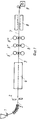
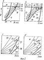
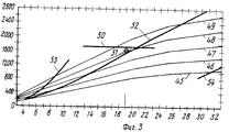
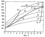
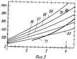
На фиг.1 структурная схема установки, вид сбоку; на фиг.2 а-d принципиальная диаграмма прокатки в четырех клетях по способу согласно изобретению; на фиг.3 -диаграмма прокатки для обжатия за проход в первой клети; на фиг.4 диаграмма прокатки для обжатия за проход во второй клети; на фиг. 5 диаграмма прокатки для обжатия за проход в третьей и последней клетях. Figure 1 is a structural diagram of the installation, side view; figure 2 a-d is a schematic diagram of rolling in four stands according to the method according to the invention; figure 3 is a rolling chart for compression for the passage in the first stand; figure 4 is a rolling chart for compression for the passage in the second stand; in FIG. 5 rolling chart for compression for the passage in the third and last stands.
На фиг.1 позицией 1 обозначена ленточная или полосовая разливочная установка, за которой установлено поперечно-резательное устройство 2, например газорезательная машина или ножницы для отрезания отлитой и выходящей из ленточной разливочной установки 1 полосы 3 на части одинаковой длины. Отдельные отрезки полосы 3 сразу же промежуточно складываются в накопительно-нагревательном устройстве 4, например, печи с роликовым подом, и доводятся до однородной температуры горячей прокатки около 1050-1100оС. С выходящей из печи части полосы 5 известным способом удаляют окалину и придают ей новую предварительную длину (не изображено). После этого отрезок полосы 5 прокатывают начисто в прокатном стане 6, состоящем из трех (или четырех) клетей (6', 6", 6lll) с исходного сечения до конечного сечения. После выхода из последней прокатной клети (6"') прокатного стана 6 с температурой при выходе 860оС готовая полоса 7 проходит участок охлаждения 8 и затем наматывается подпольной моталкой 9 при температуре около 560оС.1, reference numeral 1 denotes a tape or strip filling machine, behind which a
На фиг.2а-d схематично изображены обжатия за проход и параметры прокатки в четырех клетях, при этом на оси абсцисс указано обжатие прокаливаемой полосы по толщине dh в мм, а на оси ординат сумма эффективного момента прокатки "Ма" в кНм. On figa-d schematically shows the compression for the passage and the rolling parameters in four stands, while the abscissa axis indicates the reduction of the hardened strip in thickness dh in mm, and on the ordinate axis the sum of the effective rolling moment "Ma" in kNm.
На фиг. 2а для первой клети толщина при вводе в валки полосового материала принята за 50 мм. Максимально передаваемый момент прокатки, изображенный линией 10 при определенном диаметре 13 17 рабочего валка пересекает как горизонтальная линия кривые 11, 12, причем кривая 11 указывает на предел момента прокатки при переводе на опорные валки с коэффициентом трения μ 0,15 и кривая 12 предел момента прокатки при приводе на рабочие валки. Линии определенного диаметра 13 17 рабочего валка идут, например, снизу вверх в диапазоне 400-800 мм. При использовании почти максимального момента прокатки при определенном и относительно большом диаметре 15, 16 рабочего валка между линиями с приводом на рабочие валки в соответствии с кривой 12 можно выбрать рабочую точку 18 для первой клети так, что обжатие по толщине будет составлять 50-26=24 мм, и полоса такой толщины будет введена во вторую клеть. Соотнесенное обжатие по толщине или за проход достигает при этом 52%
На фиг.2,в позициями 19-23 снова показаны увеличивающиеся диаметры рабочих валков в зависимости от момента прокатки и обжатия по толщине. При использовании максимально передаваемого момента прокатки, изображенного линией 24, во второй клети при предпочтительно одинаковом диаметре 21, 22 рабочих валков получается рабочая точка 25 в предельно допустимом диапазоне момента прокатки при приводе на рабочие валки в соответствии с линией 26, но вне предельно допустимого диапазона момента прокатки для привода на опорные валки в соответствии с линией 27 с обжатием по толщине, например, 12 мм, поэтому остается 24-12=12 мм, что соответствует обжатию по толщине 50% Допустимый рабочий диапазон моментов прокатки между линиями 26 и 24 ограничен при максимальных значениях обжатия направо линией максимального угла захвата 28.In FIG. 2a, for the first stand, the thickness when introducing strip material into the rolls is taken to be 50 mm. The maximum transmitted rolling moment, depicted by
Figure 2, in positions 19-23 again shows the increasing diameters of the work rolls depending on the moment of rolling and compression in thickness. When using the maximum transmitted rolling moment depicted by
На фиг. 2, с позициями 29 33 снова обозначены увеличивающиеся диаметры рабочих валков в зависимости от момента прокатки и обжатия по толщине. Отрегулированное обжатие по толщине составляет в данном случае, например, 6 мм, а оставшаяся толщина 6 мм, что соответствует обжатию по высоте 50% Выбранная рабочая точка 34 находится далеко ниже максимально передаваемого момента прокатки в предельно допустимом диапазоне линии момента прокатки для привода на опорные валки согласно линии 35, поэтому рабочие валки могут приводиться в движение выборочно сами в соответствии с линией 36 или косвенно через опорные валки в соответствии с линией 35. In FIG. 2, with the
На фиг. 2,d позициями 37 41 изображены увеличивающиеся диаметры рабочих валков в зависимости от момента прокатки и обжатия по толщине. Требуемое обжатие по толщине в данном случает составляет, например, 3 мм с конечной толщиной 3 мм, что соответствует обжатию по высоте 50% Выбранная рабочая точка 42, как и на фиг.2,с находится значительно ниже максимально передаваемого момента прокатки в предельно допустимом диапазоне линий момента прокатки согласно линиям 43, 44 для привода на рабочие и опорные валки, поэтому в данном случае рабочие валки, как и в третьей клети, имеют выборочно собственный привод в соответствии с линией 44 или приводятся через опорные валки в соответствие с линией 43. In FIG. 2d,
На фиг. 3 изображены рабочие параметры для обжатия за проход в первой и трех клетей в виде диаграммы, причем на оси абсцисс указаны значения обжатия по толщине dh прокатываемого материала в мм и на оси ординат сумма эффективного момента прокатки "Ма" в кНм. Линии 45-49 соответствуют диаметрам рабочих валков, увеличивающимся с 400 до 800 мм. При использовании максимально передаваемого момента прокатки 1700 кНм в соответствии с линией 50 образуется pабочая точка 51 при диаметре рабочих валков 710 мм между линиями 48 и 49 в предельно допустимом диапазоне над линией для максимально передаваемого момента прокатки при приводе на рабочие валки в соответствии с линией 52, вне предельно допустимого диапазона для привода опорных валков в соответствии с линией 53 с обжатием по толщине 19 мм так, что от толщины 41 мм на входе остается толщина 41 мм 19 мм 22 мм, что соответствует обжатию по толщине за проход 46,34% Допустимый рабочий диапазон между линиями 52 и 50 не ограничен линией максимального угла захвата 54. In FIG. 3 shows the operating parameters for the compression for the passage in the first and three stands in the form of a diagram, and the values of compression along the thickness dh of the rolled material in mm are indicated on the abscissa axis and the sum of the effective rolling moment “Ma” in kNm on the ordinate axis. Lines 45-49 correspond to the diameters of the work rolls increasing from 400 to 800 mm. When using the maximum transmitted rolling moment of 1700 kNm in accordance with
На фиг.4 позициями 55-59 обозначены снова увеличивающиеся диаметры рабочих валков в зависимости от момента прокатки и обжатия по толщине. При использовании максимально передаваемого момента прокатки 1700 кНм в соответствии с линией 60 во второй клети при предпочтительно одинаковом диаметре рабочих валков, как и в первой клети, 710 мм между диаметрами 58 и 59 получается рабочая точка 61 в предельно допустимом диапазоне над линией для максимального передаваемого момента прокатки при переводе на рабочие валки в соответствии с линией 62, но вне предельно допустимого диапазона для привода опорных валков в соответствии с линией 63 с обжатием по толщине 14 мм, поэтому остается толщина 22-14 8 мм, что соответствует обжатию за проход 63,64% Допустимый рабочий диапазон моментов прокатки между линиями 62 и 60 при значительных обжатиях за проход ограничен направо линией максимального угла захвата 64. In figure 4, the positions 55-59 indicate the again increasing diameters of the work rolls depending on the moment of rolling and compression in thickness. When using the maximum transmitted rolling moment of 1700 kNm in accordance with
На фиг.5 позиции 65-69 обозначают линии увеличивающегося диаметра рабочих валков от 400 до 800 мм. Отрегулированное значение обжатия по толщине составляет, например, 4 мм для получения остаточной толщины 4 мм, что соответствует обжатию по высоте 50% Выбранная рабочая точка 70 с моментом прокатки 900 кНм при обжатии по толщине 4 мм расположена значительно ниже максимально передаваемого момента прокатки в предельно допустимом диапазоне линии момента прокатки для привода на опорные валки (не изображено), для привода на рабочие валки в соответствии с линией 71. In figure 5, the positions 65-69 denote the lines of increasing diameter of the work rolls from 400 to 800 mm. The adjusted value of the reduction in thickness is, for example, 4 mm to obtain a residual thickness of 4 mm, which corresponds to a reduction in height of 50%. The selected
Предлагаемые изобретением меры не ограничены примером аыполнения, изображенным на чертежах. Так, например, не выходя за рамки изобретения, можно в отдельных клетях установить рабочие валки разного диаметра и геометрической формы с целью оптимизации отдельных состояний деформации, например, в особенности в последних клетях, а также так называемые смещаемые друг относительно друга валки бутылочного типа для непрерывного изменения раствора валков в месте износа валков. Соответствующее конструктивное исполнение в соответствии с последующим применением устройства представляется специалисту. The measures proposed by the invention are not limited to the embodiment shown in the drawings. So, for example, without going beyond the scope of the invention, it is possible to install work rolls of different diameters and geometric shapes in separate stands in order to optimize individual deformation states, for example, especially in the last stands, as well as the so-called bottle-type rolls relative to each other for continuous changes in the roll solution at the place of wear of the rolls. The corresponding design in accordance with the subsequent use of the device is presented to the specialist.
Claims (3)
Applications Claiming Priority (2)
| Application Number | Priority Date | Filing Date | Title |
|---|---|---|---|
| DEP3637893.3 | 1986-11-06 | ||
| DE3637893A DE3637893C2 (en) | 1986-11-06 | 1986-11-06 | Process and plant for the production of hot-rolled steel strip and strip casting plant |
Publications (1)
| Publication Number | Publication Date |
|---|---|
| RU2057601C1 true RU2057601C1 (en) | 1996-04-10 |
Family
ID=6313346
Family Applications (1)
| Application Number | Title | Priority Date | Filing Date |
|---|---|---|---|
| SU874203574A RU2057601C1 (en) | 1986-11-06 | 1987-11-02 | Method of hot rolling of steel strip and plant for performing the method |
Country Status (18)
| Country | Link |
|---|---|
| US (1) | US4817703A (en) |
| EP (1) | EP0266564B2 (en) |
| JP (1) | JPH082449B2 (en) |
| KR (1) | KR960002400B1 (en) |
| CN (1) | CN1042204C (en) |
| AT (1) | ATE74296T1 (en) |
| BR (1) | BR8705955A (en) |
| CA (1) | CA1320063C (en) |
| DD (1) | DD262602A5 (en) |
| DE (2) | DE3637893C2 (en) |
| ES (1) | ES2029818T5 (en) |
| GR (1) | GR3004260T3 (en) |
| IN (1) | IN170340B (en) |
| LT (1) | LT3832B (en) |
| LV (1) | LV10934B (en) |
| MX (1) | MX160204A (en) |
| RU (1) | RU2057601C1 (en) |
| ZA (1) | ZA877350B (en) |
Cited By (1)
| Publication number | Priority date | Publication date | Assignee | Title |
|---|---|---|---|---|
| RU2630106C2 (en) * | 2013-03-08 | 2017-09-05 | Смс Груп Гмбх | Method of manufacture of metal strip by continuous casting and rolling |
Families Citing this family (24)
| Publication number | Priority date | Publication date | Assignee | Title |
|---|---|---|---|---|
| DE58901955D1 (en) * | 1988-03-17 | 1992-09-03 | Mannesmann Ag | PLANT FOR PRODUCING HOT-ROLLED STEEL STRIP. |
| US5307864A (en) * | 1988-05-26 | 1994-05-03 | Mannesmann Aktiengesellschaft | Method and system for continuously producing flat steel product by the continuous casting method |
| DE3839151A1 (en) * | 1988-11-17 | 1990-05-23 | Mannesmann Ag | METHOD FOR PRODUCING HOT-ROLLED STEEL STRIP FROM A STRIP-SHAPED PRE-MATERIAL |
| US5082047A (en) * | 1989-07-31 | 1992-01-21 | Bricmanage, Inc. | Method of continuously casting and rolling metallic strip |
| DE3929722A1 (en) * | 1989-09-07 | 1991-03-14 | Schloemann Siemag Ag | PLANT FOR THE PRODUCTION OF STEEL STRIP |
| NL9100911A (en) * | 1991-03-22 | 1992-10-16 | Hoogovens Groep Bv | Mfg. hot-rolled steel strip with single pass - for the sole reduction means through two-high roll stand |
| US5488987A (en) * | 1991-10-31 | 1996-02-06 | Danieli & C. Officine Meccaniche Spa | Method for the controlled pre-rolling of thin slabs leaving a continuous casting plant, and relative device |
| AT398396B (en) * | 1993-02-16 | 1994-11-25 | Voest Alpine Ind Anlagen | METHOD FOR PRODUCING A TAPE, PRE-STRIP OR A LAM |
| JP2845097B2 (en) * | 1993-03-18 | 1999-01-13 | 株式会社日立製作所 | Hot steel plate rolling equipment and rolling method |
| US5430930A (en) * | 1993-10-12 | 1995-07-11 | Italimpianti Of America, Inc. | Method of manufacturing hot strip |
| JP3063518B2 (en) * | 1993-12-27 | 2000-07-12 | 株式会社日立製作所 | Continuous casting device and continuous casting system |
| DE4402402B4 (en) * | 1994-01-27 | 2004-05-13 | Sms Demag Ag | Process for producing hot-rolled steel strip from continuously cast starting material and plant for carrying out the process |
| US5632177A (en) * | 1994-03-01 | 1997-05-27 | Hitachi, Ltd. | System and method for manufacturing thin plate by hot working |
| IT1267916B1 (en) * | 1994-03-31 | 1997-02-18 | Danieli Off Mecc | PROCEDURE FOR THE PRODUCTION OF BELT STARTING FROM THIN SLABS AND RELATIVE PLANT |
| DE19613718C1 (en) * | 1996-03-28 | 1997-10-23 | Mannesmann Ag | Process and plant for the production of hot-rolled steel strip |
| DE19725434C2 (en) * | 1997-06-16 | 1999-08-19 | Schloemann Siemag Ag | Process for rolling hot wide strip in a CSP plant |
| DE19814223A1 (en) * | 1998-03-31 | 1999-10-07 | Schloemann Siemag Ag | Process for the production of microalloyed structural steels |
| DE102006054932A1 (en) | 2005-12-16 | 2007-09-13 | Sms Demag Ag | Method and device for producing a metal strip by casting rolls |
| DE102008020412A1 (en) | 2007-08-24 | 2009-02-26 | Sms Demag Ag | Method and device for producing a metal strip by casting rolls |
| DE102008003222A1 (en) * | 2007-09-13 | 2009-03-19 | Sms Demag Ag | Compact flexible CSP system for continuous, semi-continuous and batch operation |
| CN102581008A (en) * | 2012-03-01 | 2012-07-18 | 河北钢铁股份有限公司唐山分公司 | Processing method for producing low-cost high-formability IF (interstitial-free) steel |
| CN102814323B (en) * | 2012-08-26 | 2014-07-09 | 西部钛业有限责任公司 | Processing method for rolling broad zirconium plate |
| KR101755236B1 (en) * | 2015-10-21 | 2017-07-10 | 주식회사 포스코 | Endless rolling apparatus and method |
| CN105458018B (en) * | 2016-01-13 | 2018-03-23 | 中冶东方工程技术有限公司 | Casting and rolling machine couples swing position control device and its control method with conticaster |
Family Cites Families (15)
| Publication number | Priority date | Publication date | Assignee | Title |
|---|---|---|---|---|
| US3358358A (en) * | 1964-12-31 | 1967-12-19 | United States Steel Corp | Method of reducing width of metal slabs |
| AT266362B (en) * | 1966-04-22 | 1968-11-11 | Boehler & Co Ag Geb | Method and device for the production of stretch-formed products from refractory metals, in particular from unalloyed or alloyed steels with improved quality properties |
| AT280191B (en) * | 1966-12-01 | 1970-04-10 | Gerb Boehler & Co Ag | Process for the production of rolled products from continuously cast products using two pairs of rolls |
| DE1816849C3 (en) * | 1968-12-24 | 1973-12-13 | Demag Ag, 4100 Duisburg | Process for continuous casting and subsequent rolling from the casting heat of steel |
| JPS53112247A (en) * | 1977-03-11 | 1978-09-30 | Ishikawajima Harima Heavy Ind Co Ltd | Method and apparatus for rolling continuously cast sliug |
| JPS54153750A (en) * | 1978-05-26 | 1979-12-04 | Toshiba Corp | Method and apparatus for manufacturing metal molding |
| JPS5550912A (en) * | 1978-10-12 | 1980-04-14 | Toshiba Corp | Speed controller for rolling mill |
| DE2917784A1 (en) * | 1979-05-03 | 1980-11-13 | Krupp Gmbh | METHOD FOR PRODUCING FLAT MATERIAL FROM ALUMINUM, COPPER, STEEL OR ALLOYS OF THESE MATERIALS BY MEANS OF A CONTINUOUSLY WORKING CASTING MACHINE, AND DEVICE FOR CARRYING OUT THE METHOD |
| JPS58100903A (en) * | 1981-12-09 | 1983-06-15 | Kawasaki Steel Corp | Train disposed with special continuous casting machine and hot rolling mill |
| US4519118A (en) * | 1982-10-26 | 1985-05-28 | Kennecott Corporation | Hot mill self-centering roll design |
| DE3241745C2 (en) * | 1982-11-11 | 1985-08-08 | Mannesmann AG, 4000 Düsseldorf | Process for the production of hot-rolled steel strip from continuously cast raw material in directly successive work steps |
| JPS60121009A (en) * | 1983-12-02 | 1985-06-28 | Sumitomo Metal Ind Ltd | Manufacture of hot rolled strip |
| JPS60216904A (en) * | 1984-04-13 | 1985-10-30 | Mitsubishi Heavy Ind Ltd | Rolling method of thin metallic-sheet manufactured by continuous casting |
| JPS6156708A (en) * | 1984-08-28 | 1986-03-22 | Sumitomo Metal Ind Ltd | Line of continuous hot rolling mill equipment |
| DE3525457C3 (en) * | 1985-07-17 | 1999-06-10 | Mannesmann Ag | Rolling mill for the production of hot-rolled steel strips |
-
1986
- 1986-11-06 DE DE3637893A patent/DE3637893C2/en not_active Expired - Lifetime
-
1987
- 1987-09-30 ZA ZA877350A patent/ZA877350B/en unknown
- 1987-10-03 AT AT87114449T patent/ATE74296T1/en not_active IP Right Cessation
- 1987-10-03 ES ES87114449T patent/ES2029818T5/en not_active Expired - Lifetime
- 1987-10-03 DE DE8787114449T patent/DE3777954D1/en not_active Expired - Lifetime
- 1987-10-03 EP EP87114449A patent/EP0266564B2/en not_active Expired - Lifetime
- 1987-10-27 IN IN778/MAS/87A patent/IN170340B/en unknown
- 1987-10-30 DD DD87308426A patent/DD262602A5/en not_active IP Right Cessation
- 1987-10-30 MX MX9089A patent/MX160204A/en unknown
- 1987-11-02 KR KR1019870012228A patent/KR960002400B1/en not_active IP Right Cessation
- 1987-11-02 RU SU874203574A patent/RU2057601C1/en active
- 1987-11-03 CN CN87107665A patent/CN1042204C/en not_active Expired - Lifetime
- 1987-11-05 BR BR8705955A patent/BR8705955A/en not_active IP Right Cessation
- 1987-11-05 JP JP62278437A patent/JPH082449B2/en not_active Expired - Lifetime
- 1987-11-06 CA CA000551190A patent/CA1320063C/en not_active Expired - Fee Related
- 1987-11-06 US US07/118,584 patent/US4817703A/en not_active Expired - Lifetime
-
1992
- 1992-04-02 GR GR920400611T patent/GR3004260T3/el unknown
-
1993
- 1993-06-08 LV LVP-93-520A patent/LV10934B/en unknown
-
1994
- 1994-01-13 LT LTIP1769A patent/LT3832B/en not_active IP Right Cessation
Non-Patent Citations (1)
| Title |
|---|
| Патент Германии N 3241745, кл. B 22D 11/128, опублик. 1985. * |
Cited By (1)
| Publication number | Priority date | Publication date | Assignee | Title |
|---|---|---|---|---|
| RU2630106C2 (en) * | 2013-03-08 | 2017-09-05 | Смс Груп Гмбх | Method of manufacture of metal strip by continuous casting and rolling |
Also Published As
| Publication number | Publication date |
|---|---|
| LTIP1769A (en) | 1995-07-25 |
| DE3777954D1 (en) | 1992-05-07 |
| JPS63132703A (en) | 1988-06-04 |
| IN170340B (en) | 1992-03-14 |
| LV10934A (en) | 1995-12-20 |
| CN1042204C (en) | 1999-02-24 |
| DD262602A5 (en) | 1988-12-07 |
| ES2029818T3 (en) | 1992-10-01 |
| GR3004260T3 (en) | 1993-03-31 |
| EP0266564B1 (en) | 1992-04-01 |
| ES2029818T5 (en) | 1999-11-16 |
| LV10934B (en) | 1996-06-20 |
| LT3832B (en) | 1996-04-25 |
| KR880005980A (en) | 1988-07-21 |
| BR8705955A (en) | 1988-06-14 |
| KR960002400B1 (en) | 1996-02-17 |
| EP0266564A2 (en) | 1988-05-11 |
| ATE74296T1 (en) | 1992-04-15 |
| JPH082449B2 (en) | 1996-01-17 |
| DE3637893A1 (en) | 1988-05-19 |
| DE3637893C2 (en) | 1996-02-08 |
| CA1320063C (en) | 1993-07-13 |
| EP0266564A3 (en) | 1988-09-14 |
| MX160204A (en) | 1989-12-26 |
| CN87107665A (en) | 1988-06-29 |
| ZA877350B (en) | 1989-05-30 |
| EP0266564B2 (en) | 1999-07-07 |
| US4817703A (en) | 1989-04-04 |
Similar Documents
| Publication | Publication Date | Title |
|---|---|---|
| RU2057601C1 (en) | Method of hot rolling of steel strip and plant for performing the method | |
| RU2163934C2 (en) | Method of producing hot-rolled steel strip and device for its embodiment | |
| JP3174457B2 (en) | Continuous casting direct hot rolling equipment and rolling method | |
| AU675099B2 (en) | Process for the production of a strip, a pre-strip or a slab | |
| CA2073683C (en) | System and process for forming thin flat hot rolled steel strip | |
| CN1222371C (en) | Method and installation for producing metal strips and sheets | |
| KR0179420B1 (en) | Intermediate thickness twin slab caster and inline hot strip and plate line | |
| EP0594828B2 (en) | Method and apparatus for intermediate thickness slab caster and inline hot strip and plate line | |
| CN1075964C (en) | High-speed thin-slabbing plant | |
| CN108526221A (en) | A kind of mild steel continuous casting and rolling production line and its production technology | |
| JPH07214135A (en) | Method and device for manufacture of band steel hot rolled from continuously cast material | |
| WO1993023182A9 (en) | Method and apparatus for intermediate thickness slab caster and inline hot strip and plate line | |
| US4528834A (en) | Reduced energy consumption method for rolling bars or wire rods | |
| CA2188626A1 (en) | Method to Roll Strip and Plate and Rolling Line which Performs Such Method | |
| CA2199658A1 (en) | Method for the continuous rolling of plate and/or strip and the relative continuous rolling line | |
| EP0745440B1 (en) | Hot strip rolling mill plant | |
| JP2845087B2 (en) | Continuous casting hot rolling equipment | |
| US4393680A (en) | Method for rolling rails | |
| US5983481A (en) | Method of making forged steel bar | |
| JP3067619B2 (en) | Continuous casting and rolling equipment | |
| WO1995013149A1 (en) | Slab caster and inline strip and plate apparatus | |
| CA1325326C (en) | Method of producing a steel strip having a thickness of less than 10 mm | |
| JPS57206502A (en) | Continuous rolling method for shape steel under direct feeding | |
| JPS5645201A (en) | Continuous rolling method for bar steel | |
| SU1431880A1 (en) | Method of continuous hot rolling of strips |