RU2039143C1 - Construction - Google Patents
Construction Download PDFInfo
- Publication number
- RU2039143C1 RU2039143C1 SU884356804A SU4356804A RU2039143C1 RU 2039143 C1 RU2039143 C1 RU 2039143C1 SU 884356804 A SU884356804 A SU 884356804A SU 4356804 A SU4356804 A SU 4356804A RU 2039143 C1 RU2039143 C1 RU 2039143C1
- Authority
- RU
- Russia
- Prior art keywords
- struts
- support
- beams
- strut
- attached
- Prior art date
Links
- 238000010276 construction Methods 0.000 title claims abstract description 8
- 230000000694 effects Effects 0.000 abstract description 3
- 239000000126 substance Substances 0.000 abstract 1
- 239000002184 metal Substances 0.000 description 6
- 239000002131 composite material Substances 0.000 description 5
- 239000003292 glue Substances 0.000 description 4
- 238000005452 bending Methods 0.000 description 2
- 230000006835 compression Effects 0.000 description 2
- 238000007906 compression Methods 0.000 description 2
- 239000000835 fiber Substances 0.000 description 2
- 239000000725 suspension Substances 0.000 description 2
- CIYMULYYXFTYFR-UHFFFAOYSA-N 1-(2-fluorophenyl)-1-(4-fluorophenyl)-2-(1,2,4-triazol-1-yl)ethanol;methyl n-(1h-benzimidazol-2-yl)carbamate Chemical compound C1=CC=C2NC(NC(=O)OC)=NC2=C1.C=1C=C(F)C=CC=1C(C=1C(=CC=CC=1)F)(O)CN1C=NC=N1 CIYMULYYXFTYFR-UHFFFAOYSA-N 0.000 description 1
- 238000004026 adhesive bonding Methods 0.000 description 1
- 230000032683 aging Effects 0.000 description 1
- 239000000470 constituent Substances 0.000 description 1
- 238000010586 diagram Methods 0.000 description 1
- 239000004744 fabric Substances 0.000 description 1
- 230000010006 flight Effects 0.000 description 1
- 239000012634 fragment Substances 0.000 description 1
- 230000005484 gravity Effects 0.000 description 1
- 238000009434 installation Methods 0.000 description 1
- 239000002648 laminated material Substances 0.000 description 1
- 239000000463 material Substances 0.000 description 1
- 239000007769 metal material Substances 0.000 description 1
- 230000007935 neutral effect Effects 0.000 description 1
- 229920000728 polyester Polymers 0.000 description 1
- 230000003014 reinforcing effect Effects 0.000 description 1
- 230000002441 reversible effect Effects 0.000 description 1
- 239000002689 soil Substances 0.000 description 1
- 238000003466 welding Methods 0.000 description 1
Images
Landscapes
- Assembled Shelves (AREA)
Abstract
Description
Изобретение касается общественных работ или строительства, где возможность применения балок с большим пролетом представляет собой одно из основных преимуществ, позволяющих, в частности, реализовать крупнопанельные перекрытия. The invention relates to public works or construction, where the possibility of using beams with a large span is one of the main advantages, allowing, in particular, to realize large-panel ceilings.
Изобретение относится к реализации больших пролетов таких, которые встречаются в сооружениях с большой поверхностью и в промышленных залах, комбинацией, с одной стороны, балок, предпочтительно пластинчатого типа на клею или из композиционных материалов, за исключением металлических или из бетона, с большим пролетом, составляющих параллельные стороны панелей с общепринятыми поперечными балками, а с другой стороны, металлического каркаса опоры. The invention relates to the implementation of large spans such as those found in structures with a large surface and in industrial halls, with a combination, on the one hand, of beams, preferably of plate type, with glue or composite materials, with the exception of metal or concrete, with a large span, constituting parallel sides of the panels with conventional transverse beams, and on the other hand, the metal frame of the support.
Изобретение относится к усовершенствованной системе опоры и подвески балок с большим пролетом пластинчатого типа на клею или из композиционных материалов на металлических опорных стойках, причем система разработана так, что обеспечивается преобразование вертикальной реакции веса балки в усилие подпорной арки в соответствующей стойке и создается таким образом в балке горизонтальное усилие, возникающее в продольном направлении, которое пpиводит к увеличению возможного пролета упомянутой балки. The invention relates to an improved system of support and suspension of beams with a large span of the plate type on glue or from composite materials on metal support posts, and the system is designed so that the vertical reaction of the weight of the beam to the force of the retaining arch in the corresponding rack is provided and is thus created in the beam horizontal force arising in the longitudinal direction, which leads to an increase in the possible span of said beam.
Известно сооружение, включающее опорные стойки, расположенные в пролетах между ними балки, парные подкосы, каждый из которых прикреплен нижним концом к опорной стойке и образует с продольной осью последний угол от 30 до 60о, преимущественно 45о, размещенные на верхних концах подкосов и опорных зонах балок опорные и крепежные элементы и прикрепленные к верхнему концу стойки, удерживающие продольные балки, размещенные между балками, расположенными в пролетах между стойками.A structure is known that includes support struts located in the spans between them beams, paired struts, each of which is attached with its lower end to the support strut and forms with the longitudinal axis the last angle from 30 to 60 about , mainly 45 about , located on the upper ends of the struts and support areas of beams supporting and fastening elements and attached to the upper end of the rack, holding longitudinal beams placed between beams located in the spans between the racks.
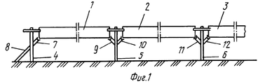
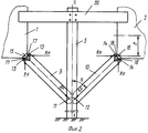
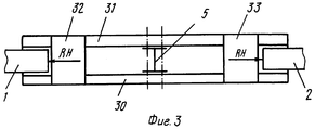
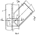
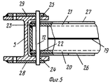
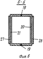
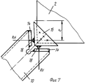
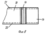
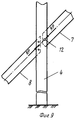
На фиг.1 показана схема сооружения; на фиг.2 вид спереди на верхнюю часть стойки с двумя подкосами, на которые оперты концы двух балок; на фиг.3 вид сверху фрагмента сооружения; на фиг.4 вид спереди на фиг.2 и 3; на фиг.5 сечение по А-А на фиг.4; на фиг.6 сечение по Б-Б на фиг.4; на фиг.7 вид верхнего конца подкоса по фиг.4,5,6 с креплением конца балки с большим пролетом; на фиг.8 вид сверху на конец подкоса, показанный на фиг.7; на фиг.9 вид спереди, каждой из крайних стоек для компенсации бокового давления, действующего со стороны балки с большим пролетом на рассматриваемую стойку. Figure 1 shows a diagram of the structure; figure 2 is a front view of the upper part of the rack with two struts, on which the ends of the two beams are supported; figure 3 is a top view of a fragment of the structure; figure 4 is a front view of figures 2 and 3; figure 5 section along aa in figure 4; Fig.6 section along BB in Fig.4; Fig.7 is a view of the upper end of the strut in Fig.4,5,6 with fastening the end of the beam with a large span; on Fig top view of the end of the strut, shown in Fig.7; Fig.9 is a front view of each of the extreme struts to compensate for the lateral pressure acting from the side of the beam with a large span to the considered strut.
Сооружение включает балки с большими пролетами 1, 2, 3 пластинчатого типа на клею или из композиционных материалов, за исключением металлических материалов или бетона, составляющих параллельные продольные стороны панелей и металлические опорные стойки 4, 5, 6 Н-образного сечения. Сооружение включает парные подкосы 7, 8 для стойки 4 и балки 1, 9, 10 для стойки 5 и балок 1 и 2, 11, 12 для стойки 6 и балок 2 и 3, и так далее до последней крайней стойки (не показана), которая находится на другом конце сооружения. The structure includes beams with large spans of 1, 2, 3 plate type on glue or made of composite materials, with the exception of metal materials or concrete, which make parallel longitudinal sides of the panels and
Теперь выявим, ссылаясь на фиг.2-9, как устроено сооружение с целью обеспечения перевода вертикальной реакции веса балки в усилие на соответствующей стойке и как создается в балке горизонтальное усилие продольного воздействия, что имеет результатом увеличение максимально возможного пролета балки такого типа. Now, let us identify, referring to FIGS. 2-9, how the structure is arranged to ensure the vertical reaction of the beam weight in the force on the corresponding strut and how the horizontal longitudinal force is created in the beam, which results in an increase in the maximum possible span of the beam of this type.
Обращаясь прежде всего и более конкретно к случаю парных подкосов 9, 10 для стойки 5 и балок 1 и 2, которые показаны на фиг.2-8, видно, что симметричное по отношению к продольной оси симметрии ХХ стойки 5 сооружение состоит из парных подкосов 9, 10, шарнирно соединенных по своим нижним концам на осях 11, 12, закрепленных штифтом на стойке 5 так, что отсутствует трение. Кроме того, эти подкосы снабжены на верхнем конце опорными уголками 13, 14. Turning primarily and more specifically to the case of paired
С другой стороны, уголки башмака 15, 16 закрепляются склейкой, сбалчиванием или заклепыванием на нижних углах соответствующих балок 1, 2, причем эти уголки имеют детали контакта 17, 18 соответствующими уголками 13, 14. Даже до более детального описания стоек видно, что для каждой из этих стоек вертикальная реакция Rу веса балки 1 или 2 преобразуется в воздействие Rр в соответствующем подкосе, что создает в балке 1 или 2 горизонтальное усилие продольного воздействия Rн, которое приводит к увеличению возможного пролета указанной балки.On the other hand, the corners of the
Важно отметить, что благодаря данной концепции действующие усилия имеют точки обязательного прохождения, а именно шарнирную ось 11, 12 для усилия Rр на подкосах 9, 10 и соединительные детали 17, 18 для вертикальной реакции Ry, практически 30 т для пролетов 24 м, а горизонтальный упор обеспечивает продольное нагружение в балке М=Rн˙e, где е расстояние РСТ между обязательной точкой прохождения горизонтального усилия Рн и нейтральным волокном балки 2.It is important to note that, thanks to this concept, the existing forces have mandatory passage points, namely, the
Теперь перейдем к детальному описанию того, как могут быть преимущественно выполнены каждый из подкосов 9, 10 по фиг.2, обращаясь при этом к фиг. 4-8. Эти подкосы должны быть обязательно разработаны так, чтобы сопротивляться продольному изгибу; каждая из них выполняется (фиг.6) продольной сваркой 19 двух асимметричных профилей Y-образного сечения 20, 21. Эти профили имеют на своих нижних концах, заостренных асимметрично (фиг.4), отверстия 22, 23, что обеспечивает поворот комплекса подкоса на оси опоры 12, зашплинтованной в отверстиях 24, 25, выполненных в полках стойки 5 Н-образного сечения. Now we turn to a detailed description of how each of the
С целью распределения локальных нагрузок как по поверхностям подкосов, так и по поверхностям соответствующих полок стойки, на подкосе закреплены усиливающие пластины, препятствующие продольному изгибу, например пластины 26, 27, а на полках стойки пластины 28, 29. In order to distribute local loads both on the surfaces of the struts and on the surfaces of the respective rack shelves, reinforcing plates are fixed on the strut, which prevent longitudinal bending, for example,
Ранее при описании фиг.2 было видно, что балка 2 опирается своим концом на верхний конец соответствующего подкоса 10 и что сооружение разработано в соответствии с изобретением таким образом, чтобы приложения усилий Ry, Rн и Rp имели обязательные точки прохождения с тем, чтобы расчет и контроль усилий был бы как можно более простым и точным.Previously, in the description of FIG. 2, it was seen that the
На фиг. 7 и 8 показана в большом масштабе предпочтительная форма реализации изобретения. In FIG. 7 and 8 show on a large scale a preferred embodiment of the invention.
В этом случае конец балки 2 снабжен концевым элементом 16 в форме уголка, каждая из полок которого снабжена соединительной деталью в виде цилиндра или полуцилиндра 18, которые оперты на соответствующий элемент 14 опорного уголка, приваренного к верхнему концу подкоса 10. Очевидно, что в этом случае вертикальные и горизонтальные усилия Ry и Rн, а также точка их приложения точно определены и контролируются с момента, когда балка 2 помещается (фиг.1) на подкосы 9, 10 стоек 5 и 6.In this case, the end of the
Горизонтальное нагружение, созданное таким образом в балке 2, позволяет, как это было показано ранее, увеличить максимально возможный пролет упомянутой балки. Кроме того, видно, что своевременно происходит автоматическое достижение старения материалов, составляющих балку, а именно склеенные слоистые или композиционные материалы, такие как пропитанная полиэфиром ткань, трубы, волокна и т.д. за исключением металла и бетона. The horizontal loading created in this way in the
Очевидно, что возможно шарнирное крепление соединения подкос-опорный элемент, в котором опорный элемент, на который оперта балка, был бы шарнирно закреплен на подкосе, но такое решение, априори, представляет собой неоспоримые трудности при монтаже и применении. Кроме того, можно понять, что концевая деталь 16 имеет лишь один соединительный цилиндр большого радиуса, опертый на две полки уголка 14 подкоса, но такое решение имеет трудности крепления единственного цилиндра на опором элементе и контроля расстояний до точки опоры как для вертикальных, так и для горизонтальных усилий Ry и Rн
Неоспоримо, что предпочтительное решение, описанное ранее, имеет явное преимущество в том, что обязательного прохождения точки указанных усилий точно определены элементами 18, уголка 16, размещенного на уголке 14, подкоса 10. Поскольку балки 1 и 2 просто помещены своими концевыми элементами 15 и 16 на подкосы 9, 10, стойка 5 продолжена вверх и снабжена в верхней части (фиг.2 и 3) двумя антиветровыми балками 30, 31, которые прикреплены в центре на полках стойки 5 Н-образного сечения и зажимают в боковом направлении верхние части балок 1 и 2, размещенные в продолжении друг друга. Кроме того, эти самые балки могут быть собраны пластинами 32, 33 и служить опорой для оборудования, например климатизаторов, нагревателей и др.Obviously, it is possible to hinge the connection of the strut-support element, in which the support element on which the beam is supported would be pivotally mounted on the strut, but such a solution, a priori, presents undeniable difficulties in installation and use. In addition, it can be understood that the
It is indisputable that the preferred solution described earlier has a clear advantage in that the obligatory passage of the points of the indicated forces is precisely determined by the
Угол θ который должен образовывать подкос 10 по отношению к вертикальной оси симметрии ХХ стойки 5 определяется в зависимости от характерных данных составляющих элементов (балки, стойки, минимальная высота под потолком и т. д.) реализуемой конструкции с большим пролетом. The angle θ that should form a
Математическая теория требует, чтобы центр тяжести балки большого пролета 2, геометрический центр концевого уголка 16, которым снабжена упомянутая балка, а также геометрический центр шарнирного соединения 12 на стойке 5 были бы расположены на одной и той же дуге круга. The mathematical theory requires that the center of gravity of the beam of the
На практике угол θ должен быть заключен между 30 и 60о, а предпочтительно, поскольку это намного проще с точки зрения практической, он должен быть равным 45о.In practice, the angle θ should be between 30 and 60 ° , and preferably, since it is much easier from a practical point of view, it should be equal to 45 ° .
В соответствии с другим признаком изобретения крайние стойки, например 4, фиг. 1 и 9, для которых эффект горизонтального нагружения Rн, который имеет место в части 1 и который преобразуется в воздействие Rр на стойку 4, не уравновешивается симметричным обратным воздействием другой балки, как это имеет место, например, в случае стойки 5, и который должен быть компенсирован ветровым подкосом 8, который прикреплен своим верхним концом к полкам стойки 4 и расположен на продолжении подкоса 7 для опоры своим нижним концом на почву, как это четко видно на фиг.1. Таким образом, сооружение находится в идеальном равновесии.According to another feature of the invention, the uprights, for example 4, FIG. 1 and 9, for which the effect of horizontal loading R n , which takes place in
Изобретение представляет собой усовершенствованное сооружение, обеспечивающее опору и подвеску балок с большим пролетом пластинчатого типа на клею или из композиционных материалов на металлические опорные стойки, имеющую на каждой стойке, по крайней мере, один подкос, шарнирно закрепленный на своем нижнем конце на указанной стойке, к которой один из концов балки с большим пролетом поддерживается стойкой; соединительные детали, расположенные на балке или на верхнем конце подкоса, и опорные элементы, расположенные на верхнем конце подкоса или на балке, на которые опираются соединительные элементы, причем расположение этих соединительных и опорных элементов таково, что вес балки производит продольную силу сжатия по оси стойки, которая создает продольную силу сжатия на балке. The invention is an improved structure that provides support and suspension of beams with a large span of the plate type on glue or from composite materials on metal support posts, having at least one strut on each rack pivotally mounted on its lower end to the specified rack, to which one of the ends of the beam with a large span is supported by the rack; connecting parts located on the beam or on the upper end of the strut, and supporting elements located on the upper end of the strut or on the beam on which the connecting elements rest, and the location of these connecting and supporting elements is such that the beam weight produces a longitudinal compression force along the axis of the strut , which creates a longitudinal compression force on the beam.
Очевидно, что настоящее изобретение не ограничивается вариантом реализации, который был описан и показан, а охватывает любые варианты, которые могут быть представлены специалистом. Obviously, the present invention is not limited to the implementation option that has been described and shown, but covers any options that may be presented by a specialist.
Claims (5)
Applications Claiming Priority (3)
| Application Number | Priority Date | Filing Date | Title |
|---|---|---|---|
| FR8702306 | 1987-02-23 | ||
| FR8702306A FR2611781B1 (en) | 1987-02-23 | 1987-02-23 | LONG-RANGE BEAM SUPPORT AND LOCKING SYSTEM |
| PCT/FR1988/000096 WO1988006214A1 (en) | 1987-02-23 | 1988-02-22 | Support and securing system for long supporting beams |
Publications (1)
| Publication Number | Publication Date |
|---|---|
| RU2039143C1 true RU2039143C1 (en) | 1995-07-09 |
Family
ID=26225795
Family Applications (1)
| Application Number | Title | Priority Date | Filing Date |
|---|---|---|---|
| SU884356804A RU2039143C1 (en) | 1987-02-23 | 1988-10-21 | Construction |
Country Status (1)
| Country | Link |
|---|---|
| RU (1) | RU2039143C1 (en) |
Cited By (1)
| Publication number | Priority date | Publication date | Assignee | Title |
|---|---|---|---|---|
| RU2372451C2 (en) * | 2005-04-14 | 2009-11-10 | Л.А.С.П. Систем Италия С.Р.Л. | Multifunctional structure used as shelter |
-
1988
- 1988-10-21 RU SU884356804A patent/RU2039143C1/en not_active IP Right Cessation
Cited By (1)
| Publication number | Priority date | Publication date | Assignee | Title |
|---|---|---|---|---|
| RU2372451C2 (en) * | 2005-04-14 | 2009-11-10 | Л.А.С.П. Систем Италия С.Р.Л. | Multifunctional structure used as shelter |
Similar Documents
| Publication | Publication Date | Title |
|---|---|---|
| US4887406A (en) | Structural member for buildings | |
| US3079649A (en) | Beams and building components | |
| US2241617A (en) | Triangular joist | |
| US4876836A (en) | Support and attachment system for long-span beams | |
| US2868146A (en) | Truss constructions | |
| JPH01315541A (en) | Roof truss | |
| JPH09328860A (en) | Roof structure and roof construction method | |
| JP3247749B2 (en) | Construction method of long span truss beams | |
| RU2488666C2 (en) | Frame of building carcass | |
| CN217557349U (en) | Light-duty composite floor of assembled | |
| JP2809430B2 (en) | Wooden building frame structure | |
| JP2592497B2 (en) | Basement frame structure | |
| JP2608987B2 (en) | Floor structure | |
| SU1122794A1 (en) | Connection joint of crane-supporting beams with column | |
| JP2811198B2 (en) | Supporting device for gable frames on gable roofs | |
| SU1654483A1 (en) | Rest unit for solid wooden girder | |
| JP2869728B2 (en) | Architectural floor frames and floor panels | |
| RU2037617C1 (en) | Multi-storied building | |
| JPH0449328Y2 (en) | ||
| JPH09310311A (en) | Truss bridge reinforcement structure | |
| JPH07113269A (en) | Unit building and joint structure of building units | |
| SU1726684A1 (en) | Joint of cross-bar and column | |
| JPH03107048A (en) | Beam and its installing method | |
| SU990987A1 (en) | Joint of under-crane girders with column | |
| SU1414934A1 (en) | Support assembly of wooden truss |
Legal Events
| Date | Code | Title | Description |
|---|---|---|---|
| MM4A | The patent is invalid due to non-payment of fees |
Effective date: 20030223 |