RU2037793C1 - Electron force converter for balance - Google Patents
Electron force converter for balanceInfo
- Publication number
- RU2037793C1 RU2037793C1 SU5012229A RU2037793C1 RU 2037793 C1 RU2037793 C1 RU 2037793C1 SU 5012229 A SU5012229 A SU 5012229A RU 2037793 C1 RU2037793 C1 RU 2037793C1
- Authority
- RU
- Russia
- Prior art keywords
- outputs
- output
- counter
- input
- inputs
- Prior art date
Links
- 239000010453 quartz Substances 0.000 claims abstract description 11
- VYPSYNLAJGMNEJ-UHFFFAOYSA-N silicon dioxide Inorganic materials O=[Si]=O VYPSYNLAJGMNEJ-UHFFFAOYSA-N 0.000 claims abstract description 11
- 238000009434 installation Methods 0.000 claims description 6
- 239000004065 semiconductor Substances 0.000 claims description 3
- 238000013016 damping Methods 0.000 claims 1
- 238000005259 measurement Methods 0.000 abstract description 5
- 239000000126 substance Substances 0.000 abstract 1
- 230000035945 sensitivity Effects 0.000 description 7
- 230000007423 decrease Effects 0.000 description 2
- 238000001208 nuclear magnetic resonance pulse sequence Methods 0.000 description 2
- 238000005452 bending Methods 0.000 description 1
- 238000006243 chemical reaction Methods 0.000 description 1
- 230000006835 compression Effects 0.000 description 1
- 238000007906 compression Methods 0.000 description 1
- 238000010586 diagram Methods 0.000 description 1
- 230000000284 resting effect Effects 0.000 description 1
- 230000001629 suppression Effects 0.000 description 1
- 239000000725 suspension Substances 0.000 description 1
- 230000001360 synchronised effect Effects 0.000 description 1
- 230000008542 thermal sensitivity Effects 0.000 description 1
Images
Landscapes
- Measuring Temperature Or Quantity Of Heat (AREA)
Abstract
Description
Изобретение относится к силоизмерительной технике, в частности к преобразователям силы для весов. The invention relates to load-measuring equipment, in particular to force transducers for scales.
Известен электронный преобразователь торговых весов, в котором преобразование измеряемого веса в электрический частотный сигнал осуществляется с помощью вибростержневого датчика. Частотный сигнал обрабатывается в микропроцессоре и поступает на индикатор [1] Недостатком преобразователя является сложность, невозможность получения заданного смещения нуля, что затрудняет его использование при определении веса "нетто", появление ложных срабатываний при разгрузке весов. Known electronic converter of trade scales, in which the conversion of the measured weight into an electrical frequency signal is carried out using a vibro rod sensor. The frequency signal is processed in the microprocessor and is sent to the indicator [1]. The disadvantage of the converter is the difficulty, the inability to obtain the specified zero offset, which makes it difficult to use when determining the net weight, the appearance of false alarms when unloading the balance.
Наиболее близким по достигаемому результату и технической сущности к изобретению является электронный преобразователь силы для весов [2] Он является более простым и позволяет взвешивать вес "нетто", имеет более широкие функциональные возможности за счет получения заданного смещения нуля. Недостатком этого преобразователя является невозможность компенсации температурной погрешности. The closest to the achieved result and technical essence to the invention is an electronic force transducer for scales [2]. It is simpler and allows you to weigh the net weight, has broader functionality by obtaining a predetermined zero offset. The disadvantage of this Converter is the inability to compensate for temperature errors.
Целью изобретения является уменьшение температурной погрешности. The aim of the invention is to reduce the temperature error.
Цель достигается тем, что в электронный преобразователь силы для весов, содержащий платформу, установленную на рычаге, на верхней и нижней поверхностях которого размещены кварцевые резонаторы, включенные в частотозадающие цепи измерительных кварцевых резонаторов, выходы которых подключены к смесителю, выход которого через формирователь импульсов соединен с входами двух ключей, управляющие входы которых подключены к выходам распределителя импульсов, вход которого соединен с выходом генератора тактовой частоты, а третий выход с первым входом триггера, второй вход которого через нормально разомкнутую кнопку подключен к шине питания, а выход триггера и четвертый выход распределителя импульсов подключены к вентилю, выход которого соединен с входом установки в нуль счетчика предварительной установки, со счетными входами этого и второго счетчиков соединены выходы ключей, входы второго счетчика соединены с выходами счетчика предварительной установки, выходы второго счетчика через регистр соединены с дешифратором, связанным с индикатором, а установочные входы этого счетчика и регистра соединены соответственно с пятым и шестым выходами распределителя
импульсов, при этом с выходами дешифратора соединены входы блока гашения незначащих цифр, вход которого связан с вторым входом триггера и входом разрешения индикатора, введены управляемый делитель частоты, формирователь интервала времени, третий ключ, генератор с термочувствительным элементом, третий счетчик и второй регистр, причем управляемый делитель частоты установлен между входом распределителя импульсов и выходом генератора тактовой частоты, который связан с формирователем интервала времени, выход которого соединен с управляющим входом третьего ключа, генератор с термочувствительным элементом через третий ключ связан с третьим счетчиком, выход которого соединен с вторым регистром, выходы которого подключены к входам управляемого делителя частоты, а установочные входы третьего счетчика и второго регистра соединены соответственно с пятым и шестым выходами распределителя импульсов.The goal is achieved in that an electronic force transducer for scales, containing a platform mounted on a lever, on the upper and lower surfaces of which there are quartz resonators included in the frequency setting circuits of the measuring quartz resonators, the outputs of which are connected to a mixer, the output of which is connected to the inputs of two keys, the control inputs of which are connected to the outputs of the pulse distributor, whose input is connected to the output of the clock generator, and the third output to the first trigger input, the second input of which is connected through a normally open button to the power bus, and the trigger output and the fourth output of the pulse distributor are connected to a valve whose output is connected to the zero input of the preset counter, the key outputs are connected to the counting inputs of this and the second counters, the inputs of the second counter are connected to the outputs of the preset counter, the outputs of the second counter are connected via a register to a decoder associated with the indicator, and the installation inputs of this counter chika and register are connected respectively to the fifth and sixth outputs of the distributor
pulses, with the outputs of the decoder are connected to the inputs of the block of insignificant digits, the input of which is connected to the second input of the trigger and the indicator enable input, a controlled frequency divider, a time interval shaper, a third key, a generator with a heat-sensitive element, a third counter and a second register are introduced, and a controlled frequency divider is installed between the input of the pulse distributor and the output of the clock generator, which is connected with the shaper of the time interval, the output of which is connected to the control the input of the third key, the generator with the thermosensitive element through the third key is connected to the third counter, the output of which is connected to the second register, the outputs of which are connected to the inputs of the controlled frequency divider, and the installation inputs of the third counter and second register are connected respectively to the fifth and sixth outputs of the pulse distributor .
Кроме того, для достижения цели в качестве термочувствительного элемента используют полупроводниковый терморезистор или кварцевый резонатор. In addition, to achieve the goal, a semiconductor thermistor or a quartz resonator is used as a thermosensitive element.
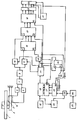
На чертеже представлена структурная схема электронного преобразователя. The drawing shows a structural diagram of an electronic converter.
Преобразователь содержит платформу 1 на свободной подвеске, опирающейся на рычаг 2, на верхней и нижней поверхностях которого размещены кварцевые резонаторы 3 и 4. Резонаторы включены в частотозадающие цепи измерительных кварцевых генераторов 5 и 6, выходы которых подключены к смесителю 7. Выход смесителя через формирователь 8 соединен с входами ключей 9 и 10, управляющие входы которых подключены к выходам распределителя 11 импульсов. Вход распределителя 11 импульсов связан с выходом генератора 12 тактовой частоты через управляемый делитель 13 частоты. Третий выход распределителя импульсов соединен с первым входом триггера 14, второй вход которого через нормально разомкнутую кнопку подключен к шине питания. Выход триггера, четвертый выход распределителя 11 импульсов подключены к вентилю 15, выход которого связан с входом установки в нуль счетчика 16 предварительной установки. Выходы ключей 9 и 10 соединены со счетными входами счетчиков 16 и 17. Входы предустановки счетчика 17 соединены с выходами счетчика 16. Выходы счетчика 17 через регистр 18 соединены с дешифратором 19, соединенным с индикатором 20. Установочные входы счетчика 17 и регистра 18 соединены с пятым и шестым выходами распределителя 11 импульсов. С выходами дешифратора 19 соединены вход устройства 21 гашения незначащих цифр, выход которого соединен с вторым выходом триггера 14 и входом разрешения индикатора 20. The converter contains a platform 1 on a free suspension, resting on a
С выходом генератора 12 тактовой частоты соединен формирователь 22 интервала времени, выход которого соединен с управляющим входом дополнительного ключа 23. Дополнительный генератор 24 с термочувствительным элементом 25 через ключ 23 связан с третьим счетчиком 26, выход которого связан с регистром 27. Регистр связан с управляемым делителем 13 частоты. Установочные входы счетчика 26 и регистра 27 соединены с пятым и шестым выходами распределителя 11 импульсов. A
Работа преобразователя осуществляется следующим образом. The operation of the Converter is as follows.
Груз размещается на платформе 1, при этом измеряемый вес преобразуется в усилие, передаваемое на рычаг 2, испытывающий при этом деформацию изгиба. Резонатор 3 уменьшает свою резонансную частоту (деформация растяжения), а резонатор 4 увеличивает (деформация сжатия). The load is placed on the platform 1, while the measured weight is converted into a force transmitted to the
Генераторы 5 и 6 возбуждают электрические колебания с частотами, близкими к резонансным частотам резонаторов. Эти частоты смешиваются в смесителе 7. Формирователь 8 выделяет импульсную последовательность с разностной частотой.
При отсутствии груза разностная частота равна fо и обусловлена неравенством резонансных частот резонаторов из-за технологического разброса. Под действием измеряемого веса Р разностная частота изменяется на величину Δ fo kP, где k коэффициент чувствительности. Знак коэффициента k может быть любым в зависимости от конкретной конструкции рычага 2.In the absence of load, the difference frequency is equal to f about and is due to the inequality of the resonant frequencies of the resonators due to the technological spread. Under the influence of the measured weight P, the difference frequency changes by Δ f o kP, where k is the sensitivity coefficient. The sign of the coefficient k can be any, depending on the specific design of the
Измерение начинается при нажатии кнопки "Сброс" при ненагруженной платформе. При этом триггер 14 открывает вентиль 15 и импульсом И1 обнуляется счетчик 16 предварительной установки. Код, соответствующий значению частоты, фиксируется в счетчике 16 и переписывается в счетчик 17. Далее импульсы частоты поступают через ключ 10 в счетчик 17, работающий в режиме вычитания. По окончании счета содержимое счетчика 17 равно 0, что индицируется индикатором 20. После установки груза на платформу частота f fo kP поступает только в счетчик 17, так как триггер 14 сброшен в нуль импульсом И4 после записи в счетчике 16 в первом цикле. По окончании счета в счетчике 16 оказывается код, соответствующий Δ f: Δ f fo I fo kP I kP. Этот код, масштабированный в единицах веса, отображается в индикаторе 20.Measurement starts when you press the "Reset" button when the platform is not loaded. In this case, the
Масштаб кода и, соответственно, показания весов определяются временем измерения Т (временными воротами), формируемым распределителем 11 импульсов из импульсной последовательности, поступающей от генератора 12 через делитель 13. Время измерения связано с периодом частоты генератора 12 Т ТтN, где N коэффициент деления делителя 13 частоты.Scale and code, respectively, indications of weights determined by measuring the time T (time gate) formed by the
Влияние температуры окружающей среды сводится к изменению начальной частоты и изменению коэффициента чувствительности по закону, близкому k ko ± Δ k(to to o), где k температурный коэффициент чувствительности.The influence of ambient temperature is reduced to a change in the initial frequency and a change in the sensitivity coefficient according to a law close to kk o ± Δ k (t o t o o ), where k is the temperature coefficient of sensitivity.
Благодаря изменению времени измерения в зависимости от температуры, происходит уменьшение температурной погрешности коэффициента чувствительности (но со знаком, противоположным знаку изменения коэффициента чувствительности). При этом код в счетчике 17 оказывается равным М (ko + Δ k Δ to I ˙ P I ˙ T Δ T Δ to), где Δ Т температурный коэффициент изменения времени измерения; Δ to- изменение температуры.Due to the change in the measurement time depending on the temperature, the temperature error of the sensitivity coefficient decreases (but with a sign opposite to the sign of the change in the sensitivity coefficient). In this case, the code in the
Из приведенного выражения следует, что если температурный коэффициент равен Δ Т Δ kT/kо, то температурная погрешность коэффициента чувствительности k оказывается скомпенсированной с точностью до величины второго порядка малости Δ k Δ T/ Δ to/2. Для реализации данного принципа компенсации коэффициент деления управляемого делителя устанавливается в виде постоянной и переменной частей. Переменная часть определяется кодом в регистре 27, куда он поступает из счетчика 26. Код в счетчике 26 образуется при подсчете импульсов частоты fDO дополнительного генератора 24. Эта частота зависит от температуры термочувствительного элемента 25, включенного в частотозадающую цепь генератора 24. Измерение этой частоты производится за фиксированный интервал времени τ, вырабатываемый формирователем 22 из тактовой частоты fт 1/Тт. В результате код в счетчике 26 равен N2 

Если требуется изменить знак компенсации, то счетчик 26 должен работать в режиме вычитания из кода М1, что осуществляется переключением его входов.If you want to change the sign of compensation, then the
Суммарный коэффициент деления делителя 13 складывается N I M1 ± fDO τ I ± Δ fΔ t τ. Слагаемое в скобках определяет постоянную часть коэффициента деления N и соответствует номинальному значению коэффициента чувствительности kо (при нормальной температуре). Масштабирование компенсирующего изменения коэффициента деления в соответствии с изложенным осуществляется изменением интервала и кода предварительной установки М1.The total division ratio of the
Поскольку формирователь 22 интервала τ связан с генератором 12, то все сигналы в устройстве оказываются синхронизированными и сброс счетчика 26 и регистра 27 можно осуществлять сигналами, идущими на счетчик 17 и регистр 18. Since the
В качестве термочувствительного элемента может быть использован полупроводниковый терморезистор или специальный кварцевый резонатор. A semiconductor thermistor or a special quartz resonator can be used as a thermosensitive element.
Claims (2)
Priority Applications (1)
| Application Number | Priority Date | Filing Date | Title |
|---|---|---|---|
| SU5012229 RU2037793C1 (en) | 1991-09-18 | 1991-09-18 | Electron force converter for balance |
Applications Claiming Priority (1)
| Application Number | Priority Date | Filing Date | Title |
|---|---|---|---|
| SU5012229 RU2037793C1 (en) | 1991-09-18 | 1991-09-18 | Electron force converter for balance |
Publications (1)
| Publication Number | Publication Date |
|---|---|
| RU2037793C1 true RU2037793C1 (en) | 1995-06-19 |
Family
ID=21589361
Family Applications (1)
| Application Number | Title | Priority Date | Filing Date |
|---|---|---|---|
| SU5012229 RU2037793C1 (en) | 1991-09-18 | 1991-09-18 | Electron force converter for balance |
Country Status (1)
| Country | Link |
|---|---|
| RU (1) | RU2037793C1 (en) |
-
1991
- 1991-09-18 RU SU5012229 patent/RU2037793C1/en active
Non-Patent Citations (2)
| Title |
|---|
| 1. Электронный преобразователь торговых весов типа 9026. Экспресс-информация. Сер.ТС-7, 1987, вып.5. Электронные торговые весы. * |
| 2. Авторское свидетельство СССР N 1657972, кл. G 01G 3/16, 1991. * |
Similar Documents
| Publication | Publication Date | Title |
|---|---|---|
| US4858145A (en) | Force measuring device | |
| US3885427A (en) | Electronic balance for measuring masses or forces | |
| EP0144834B1 (en) | Load cell type weight-measuring device | |
| CA1097703A (en) | Scale with digital display | |
| US5014058A (en) | Method and arrangement for evaluating a measurable analog electrical quantity | |
| JPH0752591Y2 (en) | Measuring device with vibration type force sensor | |
| US4770261A (en) | Weighing device | |
| US4955240A (en) | Vibration type force detector | |
| JPS5895230A (en) | Method and apparatus for electronic type temperature measurement | |
| RU2018132C1 (en) | Accelerometer | |
| JP3120883B2 (en) | Counting scale | |
| JPH0346765B2 (en) | ||
| SU514208A1 (en) | Weighting device with the calculation of the value of the weighed goods | |
| JPS6244601B2 (en) | ||
| JP2504753B2 (en) | Electronic thermometer | |
| SU1483280A1 (en) | Electronic scales | |
| SU1657972A1 (en) | Weight-measuring device | |
| SU1268960A1 (en) | Strain-gauge weight-measuring device | |
| SU1030661A1 (en) | Digital multi-integral instrument for strain-gauge type balance | |
| SU1622781A1 (en) | Method of measuring force with compensation of temperature error | |
| JP2679052B2 (en) | Multifunctional scale | |
| JP2522294B2 (en) | Electronic balance | |
| SU1688124A1 (en) | Batch weighing scale with digital control | |
| RU2062998C1 (en) | Level gauge | |
| RU1778574C (en) | Pressure-measuring apparatus |