RU194963U1 - ELECTROMECHANICAL LOCK - Google Patents
ELECTROMECHANICAL LOCK Download PDFInfo
- Publication number
- RU194963U1 RU194963U1 RU2019127598U RU2019127598U RU194963U1 RU 194963 U1 RU194963 U1 RU 194963U1 RU 2019127598 U RU2019127598 U RU 2019127598U RU 2019127598 U RU2019127598 U RU 2019127598U RU 194963 U1 RU194963 U1 RU 194963U1
- Authority
- RU
- Russia
- Prior art keywords
- crossbar
- electromechanical lock
- gearbox
- lock according
- working part
- Prior art date
Links
Images
Classifications
-
- B—PERFORMING OPERATIONS; TRANSPORTING
- B60—VEHICLES IN GENERAL
- B60R—VEHICLES, VEHICLE FITTINGS, OR VEHICLE PARTS, NOT OTHERWISE PROVIDED FOR
- B60R25/00—Fittings or systems for preventing or indicating unauthorised use or theft of vehicles
- B60R25/01—Fittings or systems for preventing or indicating unauthorised use or theft of vehicles operating on vehicle systems or fittings, e.g. on doors, seats or windscreens
-
- E—FIXED CONSTRUCTIONS
- E05—LOCKS; KEYS; WINDOW OR DOOR FITTINGS; SAFES
- E05B—LOCKS; ACCESSORIES THEREFOR; HANDCUFFS
- E05B47/00—Operating or controlling locks or other fastening devices by electric or magnetic means
Landscapes
- Engineering & Computer Science (AREA)
- Mechanical Engineering (AREA)
- Lock And Its Accessories (AREA)
Abstract
Полезная модель относится к замкам для дверей, сейфов и шкафов электромеханического типа с дистанционным управлением.Задача создания полезной модели: повышение надежности и взломостойкости замка при открывании и закрывании.Технический результат: повышение надежности и взломостойкости замка при открывании и закрывании.Решение указанных задач достигнуто в электромеханическом замке, содержащем корпус, внутри которого установлен ригель, имеющий рабочую часть, входящую при закрывании в отверстие ответной планки, соединенный с электродвигателем, отличающийся тем, что применен реверсивный электродвигатель постоянного тока, содержащий статор с обмоткой возбуждения и ротор, вал которого соединен через устройство преобразования с ригелем, обмотка возбуждения соединена электрическими проводами с блоком управления, к которому низковольтными проводами присоединен блок электропитания, а рабочий участок ригеля выполнен с внешней резьбой, на ответной плаке коаксиально отверстию установлен пустотелый цилиндр с внутренней резьбой, соответствующей внешней резьбе рабочего участка ригеля.Устройство преобразования может быть выполнено в виде редуктора, содержащего корпус и блоки шестерен, и соединенного с ним механизма преобразования вращательного движения во вращательное и поступательное.Выходной вал редуктора может быть выполнен с возможностью вращательного и поступательного движения и соединен с ригелем.Редуктор может быть выполнен планетарным.Редуктор может быть выполнен многоступенчатым.Блок управления содержит приемную антенну, соединенную с приемным устройством, выход которого соединен с входом в контроллер, выход которого соединен с входом в электронный ключ, выход которого соединен с обмоткой возбуждения.Электромеханический замок может быть выполнен врезным, при этом оси рабочей части ригеля и электродвигателя выполнены соосно.Электромеханический замок может быть выполнен накладным, при этом оси рабочей части ригеля и электродвигателя выполнены параллельно.К электрическим проводам перед блоком электропитания может быть присоединен по меньшей мере один дополнительный кабель питания со штепсельным разъемом.В качестве штепсельного разъема применен разъем МикроUSB. 9 з.п. ф-лы, 18 ил.The utility model relates to locks for doors, safes and cabinets of electromechanical type with remote control. The task of creating a utility model: improving the reliability and burglar resistance of the lock when opening and closing. Technical result: improving the reliability and burglary resistance of the lock when opening and closing. The solution to these problems was achieved in an electromechanical lock containing a housing, inside of which a crossbar is installed, having a working part, which is inserted when closing the opening of the counter plate connected to the electric motors a fuse, characterized in that a reversible DC motor is used, comprising a stator with an excitation winding and a rotor, the shaft of which is connected through a conversion device to a crossbar, the excitation winding is connected by electric wires to a control unit to which a power supply unit is connected, and the working section of the crossbar made with an external thread, a hollow cylinder with an internal thread corresponding to the external thread of the working part is installed on the counter plate coaxially to the hole crossbar assembly. The conversion device can be made in the form of a gearbox containing a housing and gear blocks, and a mechanism for converting rotational motion into rotational and translational connected to it. The output shaft of the gearbox can be made with rotational and translational motion and connected to the crossbar. be made planetary. The gearbox can be multistage. The control unit contains a receiving antenna connected to a receiving device, the output of which is connected to the input to the controller, the output of which is connected to the input to the electronic key, the output of which is connected to the field coil. The electromechanical lock can be mortise, while the axes of the working part of the crossbar and the electric motor are made coaxially. The electromechanical lock can be made laid on, while the axis of the working part of the crossbar and the electric motor are made in parallel. At least one additional power cable with a plug connector can be connected to the electric wires in front of the power supply unit. selnogo Micro-USB connector plug is applied. 9 s.p. f-ly, 18 ill.
Description
Полезная модель относится к замкам для дверей, сейфов и шкафов электромеханического типа с дистанционным управлениемThe utility model relates to locks for doors, safes and cabinets electromechanical type with remote control
Известен электромеханический замок по патенту РФ на полезную модель №93961, МПК Е05В 47/00, опубл. 10.05.2010.Known electromechanical lock according to the patent of the Russian Federation for utility model No. 93961, IPC Е05В 47/00, publ. 05/10/2010.
Этот электромеханический замок содержит корпус с размещенным в нем электродвигателем, снабженный полостью, выполненной с возможностью возвратно-поступательного движения в ней ригеля, и средство фиксации ригеля в запертом положении, ригель выполнен в виде детали, отдельной от корпуса, при этом, если один из упомянутых элементов жестко закреплен на подвижном элементе закрываемого объекта, то второй жестко закреплен на его неподвижном элементе, причем ригель выполнен в виде пластины с фигурным вырезом переменной ширины, который на участке взаимодействия ригеля с запорным элементом выполнен с поперечным размером, большим ширины прямолинейного участка фигурного выреза, начинающегося от торца ригеля, отличающийся тем, что корпус выполнен в виде стакана, а полость для возвратно-поступательного движения в ней ригеля образована наружной торцевой плоскостью корпуса и крышкой, имеющей П-образный вырез, средство фиксации ригеля в запертом положении представляет собой основание, выполненное в виде круговой пластины с призматическим запорным элементом в центре, причем основание закреплено на свободном конце вала электродвигателя таким образом, чтобы его наружная плоскость совпадала с наружной торцевой плоскостью корпуса, а призматический запорный элемент располагался в полости возвратно-поступательного движения ригеля.This electromechanical lock contains a housing with an electric motor housed in it, provided with a cavity configured for reciprocating movement of the bolt in it, and means for fixing the bolt in the locked position, the bolt is made in the form of a part separate from the housing, moreover, if one of the aforementioned elements is rigidly fixed on the movable element of the object to be closed, then the second is rigidly fixed on its fixed element, and the bolt is made in the form of a plate with a curly cut of variable width, which is the interaction of the bolt with the locking element is made with a transverse dimension greater than the width of the rectilinear section of the figured notch, starting from the end of the bolt, characterized in that the body is made in the form of a glass, and the cavity for reciprocating movement of the bolt in it is formed by the outer end plane of the body and the cover, having a U-shaped cutout, the bolt fixation means in the locked position is a base made in the form of a circular plate with a prismatic locking element in the center, and the base secured to the free end of the motor shaft so that its plane coincides with the outer end of the outer housing plane and a prismatic locking element positioned in the cavity a reciprocating movement pins.
Недостатки: сложность устройства и его относительно низкая надежность.Disadvantages: the complexity of the device and its relatively low reliability.
Известен электромеханический замок по патенту РФ на полезную модель №146759, МПК B60R 25/01, опубл. 20.10.2014, прототип.Known electromechanical lock according to the patent of the Russian Federation for utility model No. 146759, IPC B60R 25/01, publ. 10/20/2014, prototype.
Этот электромеханический замок содержит корпус с размещенными в нем ригелем и электродвигателем для перемещения ригеля посредством соединяющей их тяги, при этом в корпусе также размещена схема управления электродвигателем, а в качестве электродвигателя используется шаговый линейный электродвигатель.This electromechanical lock contains a housing with a crossbar and an electric motor located therein for moving the crossbar by means of a link connecting them, while the housing also has a motor control circuit, and a linear linear motor is used as the electric motor.
Существенные признаки, общие у предложенного технического решения и прототипа: электромеханический замок, содержащий корпус, внутри которого установлен ригель, соединенный с электродвигателем, имеющий рабочую часть, входящую при закрывании в отверстие ответной планки.The essential features common to the proposed technical solution and prototype are: an electromechanical lock containing a housing, inside which a crossbar is installed, connected to an electric motor, having a working part that enters when the mating plate is closed in the hole.
Электромеханический замок, содержащий корпус, внутри которого установлен ригель, имеющий рабочую часть, входящую при закрывании в отверстие рабочей панки, соединенный с электродвигателем.An electromechanical lock containing a housing, inside which a crossbar is installed, having a working part, which, when closed, enters the opening of the working punk connected to an electric motor.
Недостатки: низкая надежность срабатывания замка при закрывании и открывании и невозможность открыть при выходе из строя источника энергопитания.Disadvantages: low reliability of operation of the lock when closing and opening and the inability to open when the power source fails.
Задача создания полезной модели: повышение надежности замка при работе на закрывание и открывание.The task of creating a utility model: improving the reliability of the lock when working on closing and opening.
Технический результат: повышение надежности замка при работе на закрывание и открывание.Effect: increasing the reliability of the lock when working on closing and opening.
Решение указанной задачи достигнуто в электромеханическом замке, содержащем корпус, внутри которого установлен ригель, имеющий рабочую часть, соединенную с электродвигателем, входящую при закрывании в отверстие ответной планки, тем, что применен реверсивный электродвигатель постоянного тока, содержащий статор с обмоткой возбуждения и ротор, вал которого соединен через устройство преобразования с ригелем, обмотка возбуждения соединена электрическими проводами с блоком управления, к которому низковольтными проводами присоединен блок электропитания, а рабочий участок ригеля выполнен с внешней резьбой, на ответной планке коаксиально отверстию установлен пустотелый цилиндр с внутренней резьбой соответствующей внешней резьбе рабочего участка ригеля.The solution to this problem was achieved in an electromechanical lock containing a housing, inside of which a crossbar is installed, having a working part connected to an electric motor, entering when the counter plate is closed in the hole, by using a reversible DC motor containing a stator with a field winding and a rotor, shaft which is connected via a conversion device to a crossbar, the field winding is connected by electric wires to a control unit, to which a block is connected by low-voltage wires power supply, and the working section of the crossbar is made with an external thread, a hollow cylinder with an internal thread corresponding to the external thread of the working section of the crossbar is installed on the strike plate coaxially to the hole.
Устройство преобразования может быть выполнено в виде редуктора, содержащего корпус и блоки шестерен, и соединенного с ним механизма преобразования вращательного движения во вращательное и поступательное.The conversion device can be made in the form of a gearbox containing a housing and gear blocks, and a mechanism for converting rotational motion into rotational and translational connected to it.
Выходной вал редуктора может быть выполнен с возможностью вращательного и поступательного движения и соединен с ригелем.The output shaft of the gearbox can be made with the possibility of rotational and translational motion and connected to the crossbar.
Редуктор может быть выполнен планетарным.The gearbox can be made planetary.
Редуктор может быть выполнен многоступенчатым.The gearbox can be multi-stage.
Блок управления может содержать приемную антенну, соединенную с приемным устройством, выход которого соединен с входом в контроллер, выход которого соединен с входом в электронный ключ, выход которого соединен с обмоткой возбуждения.The control unit may include a receiving antenna connected to a receiving device, the output of which is connected to the input of the controller, the output of which is connected to the input of an electronic key, the output of which is connected to the excitation winding.
Электромеханический замок может быть выполнен врезным, при этом оси рабочей части ригеля и электродвигателя выполнены соосно.The electromechanical lock can be made mortise, while the axis of the working part of the crossbar and the electric motor are made coaxially.
Электромеханический замок может быть выполнен накладным, при этом оси рабочей части ригеля и электродвигателя выполнены параллельно.The electromechanical lock can be made overhead, while the axis of the working part of the crossbar and the electric motor are made in parallel.
К электрическим проводам перед блоком электропитания может быть присоединен, по меньшей мере один дополнительный кабель питания с штепсельным разъемом.At least one additional power cable with a plug connector may be connected to the electrical wires in front of the power supply unit.
В качестве штепсельного разъема применен разъем МикроUSB.A MicroUSB connector is used as a plug connector.
Сущность полезной модели поясняется на чертежах фиг. 1-18, гдеThe essence of the utility model is illustrated in the drawings of FIG. 1-18 where
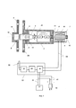
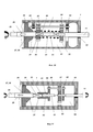
на фиг. 1 приведена основная схема электромеханического замка,in FIG. 1 shows the basic circuit of an electromechanical lock,
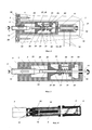
на фиг 2 приведен встроенный замок,Fig.2 shows the built-in lock,
на фиг. 3 приведен вид А встроенного электромеханического замка,in FIG. 3 shows a view A of an integrated electromechanical lock,
на фиг. 4 приведен встроенный электромеханический замок с корпусом круглого поперечного сечения,in FIG. 4 shows a built-in electromechanical lock with a housing of circular cross section,
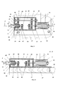
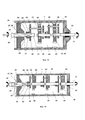
на фиг 5 приведена подробная конструкция передаточного механизма накладного электромеханического замка, без электродвигателя,in Fig.5 shows a detailed design of the transmission mechanism of the overhead electromechanical lock, without an electric motor,
на фиг. 6 приведен накладной электромеханический замок, разрез А-А,in FIG. 6 shows the consignment note electromechanical lock, section aa,
на фиг. 7 приведен механизм создания поступательного и вращательного движения,in FIG. 7 shows the mechanism for creating translational and rotational motion,
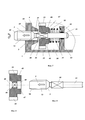
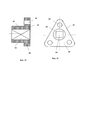
на фиг. 8 приведена ведущая шестерня,in FIG. 8 shows the pinion gear
на фиг. 9 приведен ригель, выполненный заодно с выходным валом,in FIG. 9 shows a crossbar made integrally with the output shaft,
на фиг. 10 приведен двухступенчатый редуктор с цилиндрическим зацеплением,in FIG. 10 shows a two-stage gearbox with cylindrical gearing,
на фиг. 11 приведен планетарный редуктор, одноступенчатый,in FIG. 11 shows a planetary gearbox, single-stage,
на фиг. 12 приведен двухступенчатый планетарный редуктор,in FIG. 12 shows a two-stage planetary gear,
на фиг. 13 приведен трехступенчатый планетарный редуктор,in FIG. 13 shows a three-stage planetary gearbox,
на фиг. 14 приведено водило,in FIG. 14 led carrier,
на фиг. 15 приведено водило, вид сбоку,in FIG. 15 shows a carrier, side view,
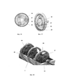
на фиг. 16 приведен одноступенчатый планетарный редуктор, вид спереди,in FIG. 16 shows a single-stage planetary gear, front view,
на фиг. 17 приведен одноступенчатый планетарный редуктор, вид сбоку,in FIG. 17 shows a single-stage planetary gearbox, side view,
на фиг. 18 приведен трехступенчатый планетарный редуктор в изометрии.in FIG. 18 shows a three-stage isometric planetary gearbox.
Условные обозначения, принятые в описании:Symbols accepted in the description:
корпус 1,
ригель 2,
рабочая часть 3,working
отверстия 4
ответное отверстие 5,
ответная планка 6,
электродвигатель 7,
статор 8,
обмотка возбуждения 9,field winding 9,
ротор 10,
вал 11,
устройство преобразования 12,
внешняя резьба 13,
электрические провода 14,
блок управления 15,
низковольтные провода 16,
блок электропитания 17,
пустотелый цилиндр 18,
внутренняя резьба 19,
редуктор 20,
механизм преобразования вращательного движения во вращательное иa mechanism for converting rotational motion into rotational and
поступательное 21,progressive 21,
ведущая шестерня 22,
ведомая шестерня 23,driven
промежуточные шестерни 24,
выходной вал 25,
радиальная стенка 26,
сквозное отверстие 27,through
внутренняя резьба 28
резьбовой участок ригеля 29,threaded section of the
участок квадратного поперечного сечения 30,a
пружина 31,
приемная антенна 32,receiving
приемное устройство 33,a receiving
контроллер 34,
электронный ключ 35,electronic key 35,
полость 36,
дверь 37,
винт 38,screw 38,
основная планка 39,
поверхность 40,
дополнительный кабель питания 41,
штепсельный разъем 42,plug
направляющая резьба 43,guide
основная стенка 44,
ступица 45,
квадратное отверстие 46,
торец 47,
коническая фаска 48,
отверстие круглого поперечного сечения 49,hole of
участок прямоугольного поперечного сечения 50,a section of a
участок круглого поперечного сечения 51,a section of
подшипник 52,bearing 52,
дополнительная опора 53,
заходная фаска 54,
планетарный редуктор 55,
солнечное колесо 56,
сателлиты 57,
ось 58,
первое водило 59,the first drove 59,
второе водило 60,the second drove 60,
радиальная пластина 61,
ступица 62,
отверстие прямоугольного поперечного сечения 63,a hole of
круглые отверстия 64,round holes 64,
планетарное колесо 65,
герметичная полость 66.sealed
Электромеханический замок (фиг. 1) содержит корпус 1, внутри которого установлен ригель 2, имеющий рабочую часть 3, выходящую из отверстия 4 и входящую при закрывании в ответное отверстие 5 ответной планки 6, соединенный с электродвигателем 7.The electromechanical lock (Fig. 1) contains a
Применен реверсивный электродвигатель постоянного тока, содержащий статор 8 с обмоткой возбуждения 9, и ротор 10, вал 11 которого соединен через устройство преобразования 12 с ригелем 2, а рабочая часть 3 ригеля 2 выполнена с внешней резьбой 13.A reversible direct current electric motor is used, comprising a
Обмотка возбуждения 9, соединена электрическими проводами 14 с блоком управления 15, к которому низковольтными проводами 16 присоединен блок электропитания 17.The field winding 9 is connected by
На ответной планке 6 коаксиально ответному отверстию 5 установлен пустотелый цилиндр 18 с внутренней резьбой 19, соответствующей внешней резьбе 13 рабочего части 3 ригеля 2.A
Устройство преобразования 12 может быть выполнено в виде редуктора 20 и механизма преобразования вращательного движения во вращательное и поступательное 21.The
Редуктор 20 может быть выполнен с цилиндрическим, или коническим, или планетарным зацеплением.The
На фиг. 2 приведен редуктор 20 с цилиндрическим зацеплением. Он содержит ведущую шестерню 22, ведомую шестерню 23, промежуточные шестерни 24 и выходной вал 25, жестко соединенный с ригелем 2. Механизм преобразования вращательного движения в поступательное 21 в этом исполнении содержит радиальную стенку 26, со сквозным отверстием 27, имеющим внутреннюю резьбу 28 и резьбовой участок ригеля 29 на выходном валу 25, участок квадратного поперечного сечения 30, и пружину 31, зажатую с натягом между торцами ведущей и ведомой шестерен 22 и 23. Ведомая шестерня 23 выполнена с возможностью осевого перемещения по участку квадратного поперечного сечения 30 выходного вала 25. Шаг внутренней резьбы 28 и резьбового участка ригеля 29 должен соответствовать шагу внешней резьбы 13 и внутренней резьбы 19. Выходной вал 25 жестко соединен с ригелем 2 для его перемещения и ввинчивания во внутреннюю резьбу 19 пустотелого цилиндра 18.In FIG. 2 shows a
Блок управления 15 может содержать приемную антенну 32 (фиг. 1), соединенную с приемным устройством 33, выход которого соединен с входом в контроллер 34, выход которого соединен с входом в электронный ключ 35, выход которого соединен с обмоткой возбуждения 9.The
Замок электромеханический может быть выполнен врезным (фиг. 2…4) и установлен в полости 36 двери 37 при помощи винтов 38, при этом оси рабочей части 3 ригеля 2 и электродвигателя 7 выполнены соосно.The electromechanical lock can be made mortise (Fig. 2 ... 4) and installed in the
На фиг. 4 приведен электромеханический замок с корпусом круглого поперечного сечения. Он имеет ригель 2 с рабочей частью по всей его поверхности и устройство преобразования 12, выполненное внутри ригеля 2. Замок имеет минимальные габариты.In FIG. 4 shows an electromechanical lock with a housing of circular cross section. It has a
Замок электромеханический во всех модификациях имеет основную планку 39.The electromechanical lock in all versions has a
Замок электромеханический может быть выполнен накладным (фиг. 4-8) и установлен на поверхности 40 двери 35, при этом оси рабочей части 3 ригеля 2 и электродвигателя 7 выполнены параллельно.The electromechanical lock can be made overhead (Fig. 4-8) and mounted on the
К низковольтным проводам 16 может быть присоединен (фиг. 1), по меньшей мере, один дополнительный кабель питания 41 со штепсельным разъемом 42 для подсоединения внешнего источника энергопитания (не показан).At least one
В качестве штепсельного разъема 42 может быть применен разъем МикроUSB.As a
Возможно применение редукторов любой схемы в той числе с цилиндрическими шестернями, коническими шестернями, или планетарных редукторов. Возможно применение многоступенчатых редукторов.It is possible to use any type of gearboxes including those with spur gears, bevel gears, or planetary gearboxes. Perhaps the use of multi-stage gearboxes.
На фиг. 2-9 приведены электромеханические замки с редукторами с цилиндрическим зацеплением. Электромеханические замки (фиг. 7) содержат направляющую резьбу 43, выполненную в основной стенке 44 корпуса 1. Ведомая шестерня 23 содержит ступицу 45, квадратное отверстие 46, торец 47, коническую фаску 48, отверстие круглого поперечного сечения 49.In FIG. 2-9 are shown electromechanical locks with gears with cylindrical gearing. Electromechanical locks (Fig. 7) contain a
Ригель 2 содержит (фиг. 9) участок прямоугольного поперечного сечения 50, участок круглого поперечного сечения 51,установленный на подшипнике 52, выполненном в дополнительной опоре 53 (фиг. 7).The
На конце рабочей части 3 ригеля 2 может быть выполнена заходная фаска 54.At the end of the working
На фиг. 10 приведен электромеханический замок с двухступенчатым редуктором с цилиндрическим зацеплением. Применение таких редукторов требует электродвигатель 7 большой мощности.In FIG. 10 shows an electromechanical lock with a two-stage gearbox with cylindrical gearing. The use of such gearboxes requires an
На фиг. 11 изображен одноступенчатый планетарный редуктор 55, который содержит: солнечное колесо 56, сателлиты 57, обычно 3 шт., оси 58 для установки сателитов 57, первое водило 59 и второе водило 60 по обе стороны солнечного колеса 56.In FIG. 11 depicts a single-stage
На фиг. 12 приведен двухступенчатый планетарный редуктор, а на фиг. 12 - трехступенчатый планетарный редуктор, который может в 100 раз уменьшить частоту вращения вала 11 электродвигателя и во столько же раз увеличить крутящий момент.In FIG. 12 shows a two-stage planetary gearbox, and FIG. 12 - a three-stage planetary gearbox, which can 100 times reduce the frequency of rotation of the
Первое водило 59 (фиг. 14 и 15) содержит радиальную пластину 61 со ступицей 62, в которой выполнено отверстие прямоугольного поперечного сечения 63 и три круглых отверстия 64 под оси 58. На корпусе 1 закреплено планетарное колесо 65. Планетарный редуктор размещен в герметичной полости 66, заполненной смазкой, (фиг. 11) для увеличения срока службы.The first carrier 59 (Figs. 14 and 15) contains a
Применение многоступенчатого планетарного редуктора (фиг. 16-18) наиболее перспективно, но он более сложен варианта на фиг. 4.The use of a multi-stage planetary gearbox (Fig. 16-18) is the most promising, but it is a more complicated variant of Fig. 4.
На фиг. 12 приведен двухступенчатый планетарный редуктор, а на фиг. 13 и 15 - трехступенчатый планетарный редуктор. Применение трехступенчатого планетарного редуктора позволит снизить частоту вращения выходного вала по сравнению с валом 11 электродвигателя 7 в 100 раз. Аналогично в 100 раз увеличится крутящий момент на выходе. Это позволит уменьшить габариты замка и мощность и габариты электродвигателя и осуществить его энергоснабжение от аккумуляторной батареи 12-18 В, безопасного в применении и используемого в бытовых приборах.In FIG. 12 shows a two-stage planetary gearbox, and FIG. 13 and 15 - a three-stage planetary gear. The use of a three-stage planetary gear will reduce the speed of the output shaft in comparison with the
РАБОТА УСТРОЙСТВАDEVICE OPERATION
Электромеханический замок монтируют на дверь 37 одним из способов (фиг. 2…5). После этого выходят из помещения и по сигналу с пульта управления (не показан) подают код на закрытие на приемную антенну 32. Сигнал расшифровывает приемное устройство 33, передает его на контроллер 34, который распознает сигнал и при правильном сигнале передает команду на электронный ключ 35 для подачи напряжения на обмотку возбуждения 9 электродвигателя 7. Ротор 10 вращается в сторону «закрытия» и поворачивает вал 11 на несколько оборотов. В устройстве преобразования 12 частота вращения вала 11 уменьшается, крутящий момент на выходном валу 25 возрастает в несколько раз и одновременно совершает поступательное движение в сторону ответной планки 6. Рабочая часть 3 ригеля 2 ввинчивается в отверстие 5 ответной планки 8 до упора.An electromechanical lock is mounted on the
РАБОТА УСТРОЙСТВА ПРИ ОТКАЗЕ БЛОКА ЭНЕРГОПИТАНИЯOPERATION OF THE DEVICE FOR FAILURE OF THE POWER SUPPLY UNIT
При отказе блока электропитания 17, используют внешний источник электропитания (не показан), который подключают через штепсельный разъем 42 (фиг. 1) можно открыть электромеханический замок. Для этого вводят код открывания с внешнего пульта управления (на фиг. 1-18 не показан).In case of failure of the
Естественно, злоумышленник, не знающий кода открывания замка, не может воспользоваться внешним источником электропитания.Naturally, an attacker who does not know the lock unlock code cannot use an external power source.
Применение полезной модели позволилоThe application of the utility model allowed
повысить надежность срабатывания механизма замка на закрывание и открывание за счет применения реверсивного электродвигателя постоянного тока, содержащего статор с обмоткой возбуждения, и ротор, вал которого соединен через устройство преобразования с ригелем, обмотка возбуждения соединены электрическими проводами с блоком управления, к которому низковольтными проводами присоединен блок электропитания, а рабочий участок ригеля выполнен с внешней резьбой, на ответной планке коаксиально отверстию установлен пустотелый цилиндр с внутренней резьбой соответствующей внешней резьбе рабочего участка ригеля,to increase the reliability of the operation of the lock mechanism for closing and opening due to the use of a reversible DC motor containing a stator with an excitation winding, and a rotor whose shaft is connected through a conversion device with a crossbar, the excitation winding is connected by electric wires to the control unit, to which a block is connected by low-voltage wires power supply, and the working section of the crossbar is made with an external thread, a hollow cylinder with an internal the early thread corresponding to the external thread of the working section of the crossbar,
уменьшить размеры, габариты и вес замка и упростить его конструкцию,reduce the size, dimensions and weight of the lock and simplify its design,
использовать замок в системе «умный дом»,use the lock in the "smart home" system,
обеспечить его аварийное открытие при выходе из строя источника энергопитания за счет применения дополнительного кабеля со штепсельным разъемом,ensure its emergency opening in case of failure of the power source due to the use of an additional cable with a plug connector,
расширить номенклатуру изделий определенного назначения - электромеханических замков при условии обеспечения его функционального назначения.expand the range of products for a specific purpose - electromechanical locks, provided that it is functional.
Claims (10)
Priority Applications (1)
| Application Number | Priority Date | Filing Date | Title |
|---|---|---|---|
| RU2019127598U RU194963U1 (en) | 2019-08-30 | 2019-08-30 | ELECTROMECHANICAL LOCK |
Applications Claiming Priority (1)
| Application Number | Priority Date | Filing Date | Title |
|---|---|---|---|
| RU2019127598U RU194963U1 (en) | 2019-08-30 | 2019-08-30 | ELECTROMECHANICAL LOCK |
Publications (1)
| Publication Number | Publication Date |
|---|---|
| RU194963U1 true RU194963U1 (en) | 2020-01-09 |
Family
ID=69140907
Family Applications (1)
| Application Number | Title | Priority Date | Filing Date |
|---|---|---|---|
| RU2019127598U RU194963U1 (en) | 2019-08-30 | 2019-08-30 | ELECTROMECHANICAL LOCK |
Country Status (1)
| Country | Link |
|---|---|
| RU (1) | RU194963U1 (en) |
Cited By (1)
| Publication number | Priority date | Publication date | Assignee | Title |
|---|---|---|---|---|
| RU238881U1 (en) * | 2025-06-10 | 2025-11-17 | Общество с ограниченной ответственностью "Лаборатория Кьюту" | ELECTRONIC LOCK |
Citations (6)
| Publication number | Priority date | Publication date | Assignee | Title |
|---|---|---|---|---|
| EP0780531A1 (en) * | 1995-12-18 | 1997-06-25 | James Salvatore Bianco | Compact electronic lock |
| US20070257773A1 (en) * | 2006-04-26 | 2007-11-08 | Compx International Inc. | Field retrofittable refrigerator lock with audit trail |
| RU90107U1 (en) * | 2009-09-09 | 2009-12-27 | Алексей Юрьевич Замесов | AUTONOMOUS ELECTROMECHANICAL LOCK FOR HOME AND OFFICE FURNITURE WITH REMOTE CONTROL |
| RU99519U1 (en) * | 2009-12-25 | 2010-11-20 | Владимир Юрьевич Петелин | ELECTROMECHANICAL LOCK DRIVE |
| RU146485U1 (en) * | 2014-08-04 | 2014-10-10 | Общество с ограниченной ответственностью "ЭмТиАй" | ELECTROMECHANICAL LOCK WITH LOCK |
| RU146759U1 (en) * | 2014-07-28 | 2014-10-20 | Закрытое Акционерное Общество "БИ-СИСТЕМ" | ELECTROMECHANICAL LOCK |
-
2019
- 2019-08-30 RU RU2019127598U patent/RU194963U1/en not_active IP Right Cessation
Patent Citations (6)
| Publication number | Priority date | Publication date | Assignee | Title |
|---|---|---|---|---|
| EP0780531A1 (en) * | 1995-12-18 | 1997-06-25 | James Salvatore Bianco | Compact electronic lock |
| US20070257773A1 (en) * | 2006-04-26 | 2007-11-08 | Compx International Inc. | Field retrofittable refrigerator lock with audit trail |
| RU90107U1 (en) * | 2009-09-09 | 2009-12-27 | Алексей Юрьевич Замесов | AUTONOMOUS ELECTROMECHANICAL LOCK FOR HOME AND OFFICE FURNITURE WITH REMOTE CONTROL |
| RU99519U1 (en) * | 2009-12-25 | 2010-11-20 | Владимир Юрьевич Петелин | ELECTROMECHANICAL LOCK DRIVE |
| RU146759U1 (en) * | 2014-07-28 | 2014-10-20 | Закрытое Акционерное Общество "БИ-СИСТЕМ" | ELECTROMECHANICAL LOCK |
| RU146485U1 (en) * | 2014-08-04 | 2014-10-10 | Общество с ограниченной ответственностью "ЭмТиАй" | ELECTROMECHANICAL LOCK WITH LOCK |
Cited By (1)
| Publication number | Priority date | Publication date | Assignee | Title |
|---|---|---|---|---|
| RU238881U1 (en) * | 2025-06-10 | 2025-11-17 | Общество с ограниченной ответственностью "Лаборатория Кьюту" | ELECTRONIC LOCK |
Similar Documents
| Publication | Publication Date | Title |
|---|---|---|
| US8671723B2 (en) | Micro motor locking system | |
| US7522042B2 (en) | Door accessory power system | |
| EP0226529A2 (en) | Electric door lock actuator | |
| EP4217568B1 (en) | Drive device for moving a leaf | |
| US4858452A (en) | Non-commutated linear motor | |
| GB2426786A (en) | Electromechanical push to close latch | |
| EP2813647B1 (en) | Electromechanical lock | |
| CN108266084A (en) | It is a kind of that manually operable electronic shutter door actuating device and its method of work are realized by electromagnetic clutch | |
| EP3510692A1 (en) | Drive device for a window lifter having an external rotor motor | |
| CN106121384A (en) | Anti-accident mechanical locking device and door opening and closing method for swing electric automatic door | |
| CN110067452B (en) | Outdoor electrical cabinet | |
| DE102020125098A1 (en) | Method for pivoting a wing with a drive device and drive device for pivoting a wing | |
| CN213304652U (en) | Looped netowrk cabinet based on high security performance locking device of thing networking | |
| CN201033977Y (en) | Intelligent burglar-proof door lock | |
| RU2710682C1 (en) | Electromechanical lock | |
| CN211201430U (en) | Chip type inner door lock device with safety alarm function | |
| CN110273591A (en) | A kind of single-power intelligent miniature lock | |
| JP3628872B2 (en) | Electric door lock drive device | |
| KR200360653Y1 (en) | Motor-Driven Mortise Locking Device for Use in Digital Doorlock | |
| DE102020125102A1 (en) | Drive device for moving a wing | |
| CN212359389U (en) | Rack and pinion drawer fingerprint lock | |
| US12516563B2 (en) | Drive device for pivoting a leaf, hinged door or casement window assembly, and use of the drive device for a hinged door or casement window drive | |
| CN213953333U (en) | Manual opening device for electric door | |
| CN221256416U (en) | Magnetic door lock | |
| DE102010028425A1 (en) | Closure device has electromotive movable component and another static component, where safety unit is provided for monitoring movement of former component and for automatically disrupting movement of component in safety case |
Legal Events
| Date | Code | Title | Description |
|---|---|---|---|
| MM9K | Utility model has become invalid (non-payment of fees) |
Effective date: 20200831 |