RU186047U1 - DEVICE FOR MOUNTING THE MODULE OF HINGED FACING PANELS TO THE BUILDING FACADE - Google Patents
DEVICE FOR MOUNTING THE MODULE OF HINGED FACING PANELS TO THE BUILDING FACADE Download PDFInfo
- Publication number
- RU186047U1 RU186047U1 RU2018131544U RU2018131544U RU186047U1 RU 186047 U1 RU186047 U1 RU 186047U1 RU 2018131544 U RU2018131544 U RU 2018131544U RU 2018131544 U RU2018131544 U RU 2018131544U RU 186047 U1 RU186047 U1 RU 186047U1
- Authority
- RU
- Russia
- Prior art keywords
- bracket
- module
- pad
- facade
- profile
- Prior art date
Links
Images


Classifications
-
- E—FIXED CONSTRUCTIONS
- E04—BUILDING
- E04F—FINISHING WORK ON BUILDINGS, e.g. STAIRS, FLOORS
- E04F13/00—Coverings or linings, e.g. for walls or ceilings
- E04F13/07—Coverings or linings, e.g. for walls or ceilings composed of covering or lining elements; Sub-structures therefor; Fastening means therefor
- E04F13/072—Coverings or linings, e.g. for walls or ceilings composed of covering or lining elements; Sub-structures therefor; Fastening means therefor composed of specially adapted, structured or shaped covering or lining elements
-
- E—FIXED CONSTRUCTIONS
- E04—BUILDING
- E04F—FINISHING WORK ON BUILDINGS, e.g. STAIRS, FLOORS
- E04F13/00—Coverings or linings, e.g. for walls or ceilings
- E04F13/07—Coverings or linings, e.g. for walls or ceilings composed of covering or lining elements; Sub-structures therefor; Fastening means therefor
- E04F13/21—Fastening means specially adapted for covering or lining elements
- E04F13/24—Hidden fastening means on the rear of the covering or lining elements
Abstract
Настоящая полезная модель относится к области промышленного и гражданского строительства, а именно к конструкциям для облицовки навесных вентилируемых фасадов (НВФ) строящихся и реконструируемых зданий и сооружений. Устройство для крепления модуля навесных облицовочных панелей на фасад здания включает модуль с облицовочными панелями, состоящий из вертикальных направляющих с закрепленной на них панелью, кронштейн, крепежные элементы, крепежную накладку, представляющую собой накладку с регулировочным болтом с пружиной и язычком, образующих таким образом защелку в верхней части профиля. Техническим результатом является повышение эстетичности за счет скрытого крепления, повышение качества за счет возможности изготовления готовых модулей в цеховых условиях на автоматизированном оборудовании, скорость монтажа, за счет навешивания готовых модулей на фасад, расширение возможностей изготовления нестандартных архитектурных элементов и форм, возможность «горячей» замены модуля без демонтажа смежных элементов.3 ил.This utility model relates to the field of industrial and civil construction, and in particular to structures for cladding ventilated facades (NVF) of buildings under construction and reconstructed. A device for attaching a module of hinged cladding panels to a building facade includes a module with cladding panels, consisting of vertical rails with a panel fixed to them, a bracket, fasteners, a fastening plate, which is a plate with an adjusting bolt with a spring and a tongue, thus forming a latch in top of the profile. The technical result is to increase aesthetics due to hidden fastening, improving quality due to the possibility of manufacturing finished modules in workshop conditions on automated equipment, the speed of installation, by hanging finished modules on the facade, expanding the possibilities of manufacturing non-standard architectural elements and shapes, the possibility of "hot" replacement module without dismantling adjacent elements. 3 ill.
Description
Настоящая полезная модель относится к области промышленного и гражданского строительства, а именно к конструкциям для облицовки навесных вентилируемых фасадов (НВФ) строящихся и реконструируемых зданий и сооружений.This utility model relates to the field of industrial and civil construction, and in particular to structures for cladding ventilated facades (NVF) of buildings under construction and reconstructed.
Из уровня техники известно устройство для крепления навесных облицовочных панелей из керамического гранита на фасадах зданий скрытым способом (патент на изобретение RU 2403355, опубл.: 10.11.2010 Бюл. №31). Устройство для крепления облицовочных панелей к навесному вентилируемому фасаду включает верхний и нижний захваты. Верхний захват выполнен с возможностью размещения его части в продольном пропиле на верхней торцевой части облицовочной панели, а нижний захват выполнен с возможностью размещения его части в продольном пропиле на нижней части облицовочной панели. Верхний и нижний захваты жестко соединены между собой планкой с образованием модульного элемента крепления. Планка со стороны верхнего захвата снабжена кронштейном, часть которого, предназначенная для крепления к направляющей навесного вентилируемого фасада, выполнена с отгибом, а со стороны нижнего захвата планка снабжена зацепом, выполненным с возможностью скользящего соединения с отгибом кронштейна нижерасположенной планки. Недостатками данного технического решения являются:The prior art device for mounting hinged cladding panels of ceramic granite on the facades of buildings in a hidden way (patent for invention RU 2403355, publ.: 10.11.2010 Bull. No. 31). A device for attaching cladding panels to a hinged ventilated facade includes upper and lower grips. The upper grip is made with the possibility of placing its part in the longitudinal cut on the upper end part of the cladding panel, and the lower grip is made with the possibility of placing its part in the longitudinal cut on the lower part of the cladding panel. The upper and lower grips are rigidly interconnected by a strip with the formation of a modular fastener. The bar on the upper grip side is provided with a bracket, a part of which is intended for fastening to the guide of the hinged ventilated facade, is bent, and on the side of the lower grip the bar is equipped with a hook made with the possibility of sliding connection with the bend of the bracket of the lower bar. The disadvantages of this technical solution are:
- трудоемкость изготовления продольных пропилов в облицовочных плитах, и возникновение отбраковки во время пропила;- the complexity of manufacturing longitudinal cuts in the facing plates, and the occurrence of rejection during the cut;
- ограничения в минимальной толщине облицовочных плит, невозможность применения тонкостенных материалов;- restrictions on the minimum thickness of facing plates, the impossibility of using thin-walled materials;
- необходимость герметизации данных пропилов с целью предотвращения разрушения при циклах замерзания-оттаивания;- the need to seal these cuts in order to prevent destruction during freeze-thaw cycles;
- ограничения по размерам (длине и ширине) отдельных плит ввиду необходимости компенсации разницы линейных температурных расширений материалов;- restrictions on the sizes (length and width) of individual plates due to the need to compensate for the difference in linear thermal expansion of materials;
- невозможность крепления панели сложной геометрической формы (треугольные, либо с архитектурными изгибами).- the impossibility of attaching panels of complex geometric shapes (triangular, or with architectural bends).
Известно устройство для крепления облицовочных плит (патент на полезную модель RU 85519, опубл.: 10.08.2009 Бюл. №22), включающее кронштейны из уголка, закрепленные с помощью анкеров на поверхности стены здания, на перпендикулярных к стене полках которого закреплен несущий профиль П-образного сечения с отогнутыми во внутрь кромками полок, внутри несущего профиля с возможностью перемещения установлена салазка с профилем П-образного сечения, в которой крепятся скобы-зацепы облицовочных плит, кронштейны из уголка, закрепляемые на стене здания, выполнены с полками одинаковой длины или с полкой, расположенной перпендикулярно к стене здания, удлиненной и снабженной удлинителем П-образного сечения с отогнутыми во внутрь кромками полок с возможностью размещения за его кромками удлиненной полки кронштейна, при этом на кронштейне и удлинителе кронштейна выполнены глухие продольные отверстия для закрепления удлинителя на кронштейне с возможностью изменения длины полки, передвижная салазка снабжена штифтом, закрепленным на полках П-образного профиля с выходом его краев за наружные поверхности полок, а на стенке ее выполнены отходящие в противоположные стороны от боковых полок опорные полки, причем устройство дополнительно снабжено дренаж-фиксатором П-образного профиля с отгибом полок наружу, установленным в местах разрыва несущего профиля и закрепленным с одной стороны на стенке несущего профиля и с закреплением его полок на вертикальных полках-загибах облицовочных плит. Недостатками данного технического решения являются:A device for attaching facing plates is known (patent for utility model RU 85519, publ.: 08/10/2009 Bull. No. 22), including brackets from the corner, fixed with anchors on the surface of the wall of the building, on the shelves perpendicular to the wall of which the supporting profile P is fixed -shaped section with the edges of the shelves bent inward, a slide with a profile of a U-shaped section is mounted inside the bearing profile with the possibility of movement, in which the bracket-hooks of the facing plates are attached, the brackets from the corner fixed on the wall of the building, They are available with shelves of the same length or with a shelf perpendicular to the wall of the building, elongated and equipped with an extension of a U-shaped section with the edges of the shelves bent inward with the possibility of placing beyond its edges an elongated shelf of the bracket, with blind longitudinal holes made on the bracket and extension of the bracket for fixing the extension cord on the bracket with the possibility of changing the length of the shelf, the movable slide is equipped with a pin mounted on the shelves of the U-shaped profile with the exit of its edges beyond the outer surfaces shelf shelves, and on its wall there are support flanges extending in opposite directions from the side shelves, and the device is additionally equipped with a U-shaped drainage-lock with the shelves bent outward, installed at the points of rupture of the load-bearing profile and fixed on one side to the wall of the load-bearing profile and with fixing its shelves on vertical shelves-bends of facing plates. The disadvantages of this technical solution are:
- невозможность крепления алюминиевых композитных панелей скрытым листовым способом с учетом требований к пожарной безопасности;- the impossibility of fixing aluminum composite panels with a hidden sheet method, taking into account fire safety requirements;
- отсутствие возможности регулировки в горизонтальной плоскости фасада для подгонки внешних швов;- the lack of adjustment in the horizontal plane of the facade to fit the external seams;
-отсутствие возможности «горячей» замены вышедшего из строя элемента фасада;-lack of the possibility of "hot" replacement of a failed facade element;
- невозможность предварительного изготовления модульных готовых конструкций в производственных условиях;- the impossibility of pre-manufacturing modular finished structures in a production environment;
- при изготовлении кассет большой перерасход материала - до 40%;- in the manufacture of cassettes a large overspending of material - up to 40%;
- отсутствие возможности «горячей» замены вышедшего из строя элемента фасада;- the lack of the possibility of "hot" replacement of a failed facade element;
- невозможность крепления панели сложной геометрической формы (треугольные, либо с архитектурными изгибами).- the impossibility of attaching panels of complex geometric shapes (triangular, or with architectural bends).
Наиболее близким к заявленному техническому решению является устройство для крепления навесных облицовочных панелей на фасадах зданий скрытым способом (патент на изобретение RU 2514029, опубл.: 27.04.2014 Бюл. №12). Устройство для крепления навесных облицовочных панелей на фасадах зданий скрытым способом включает вертикальные направляющие, выполненные с пазами, крепежные элементы, выполненные в виде полки, содержащей основание, причем крепежные элементы выполнены с возможностью установки их в пазы, выполненные в вертикальных направляющих, зацепления с ответными крепежными элементами, установленными на тыльной стороне облицовочных панелей, с образованием узла крепления, с возможностью поворота относительно оси упомянутых пазов, при этом ответные крепежные элементы содержат котировочные винты, закреплены при помощи анкерных дюбелей, а один из ответных крепежных элементов содержит фиксатор, выполненный в виде скобы. Недостатками данного технического решения являются:Closest to the claimed technical solution is a device for mounting hinged cladding panels on the facades of buildings in a hidden way (patent for invention RU 2514029, publ.: 04/27/2014 Bull. No. 12). The device for mounting the hinged cladding panels on the facades of buildings in a hidden way includes vertical guides made with grooves, fasteners made in the form of a shelf containing a base, and the fasteners are made with the possibility of installing them in grooves made in vertical guides, meshing with mating fasteners elements mounted on the back of the cladding panels, with the formation of the mount, with the possibility of rotation about the axis of the mentioned grooves, e fasteners contain quotation screws, secured with anchor dowels, and one of the response fasteners contains a latch made in the form of a bracket. The disadvantages of this technical solution are:
- крепление механическим способом возможно только в однородных твердотельных материалах и имеет ограничение по минимальной толщине для удержания крепежного элемента и невозможно в алюминиевых композитных панелях;- fastening by mechanical means is possible only in homogeneous solid-state materials and has a limitation on the minimum thickness to hold the fastener and is impossible in aluminum composite panels;
- высокая трудоемкость изготовления и зачастую высокий процент отбраковки в таких материалах как керамогранит;- the high complexity of manufacturing and often a high reject rate in materials such as porcelain stoneware;
- отсутствие возможности «горячей» замены вышедшего из строя элемента фасада, то есть для того, чтобы заменить разбитую плитку необходимо разобрать до ближайшего проема;- the lack of the possibility of "hot" replacement of a failed facade element, that is, in order to replace a broken tile, it is necessary to disassemble to the nearest opening;
- невозможность сборки модульных конструкций на производстве;- the impossibility of assembling modular structures in production;
- невозможность крепления панели сложной геометрической формы (треугольные, либо с архитектурными изгибами).- the impossibility of attaching panels of complex geometric shapes (triangular, or with architectural bends).
Заявляемое техническое направлено на решение задач по ускорению монтажа/демонтажа модулей на фасад здания.The claimed technical is aimed at solving problems of accelerating the installation / dismantling of modules on the facade of the building.
Заявленное техническое решение включает в себя:The claimed technical solution includes:
3) специальные кронштейны, которые позволяют навешивать готовые модули и регулировать их в трех плоскостях;3) special brackets that allow you to hang ready-made modules and adjust them in three planes;
4) накладки в профиль, позволяющие регулировать панели в вертикальной плоскости и осуществлять «горячую» замену модуля на готовом фасаде, без демонтажа смежных конструкций.4) lining in the profile, allowing you to adjust the panel in a vertical plane and carry out a "hot" replacement of the module on the finished facade, without dismantling the adjacent structures.
Задачи решаются за счет того, что устройство для крепления модуля навесных облицовочных панелей на фасад здания включает кронштейн, крепежные элементы, кронштейн представляет собой П-образный профиль с наличием отверстий для крепления к фасаду здания, и наличием отверстий в боковых стенках с установкой в них подвижного штифта, на который вешается и закрепляется вертикальная направляющая, штифт выполнен в форме цилиндрического стержня длиной больше ширины кронштейна, а часть стержня, которая ограничивается боковыми стенками кронштейна выполнена толщиной большей размера отверстий, в которые вставлен этот стержень; устройство также содержит крепежную накладку, представляющую собой накладку с регулировочным болтом с пружиной и язычком, образующих таким образом защелку в верхней части профиля, при этом накладка располагается внутри вертикальной направляющей и крепится к ней с помощью заклепок, в верхней части накладка ограничена площадкой, выполненной размером больше отверстия направляющей, в верхней площадке накладки выполнено отверстие с резьбой, через которое проходит регулировочный болт, при этом накладка аналогично вертикальной направляющей имеет вырез для крепления к штифту кронштейна.The problems are solved due to the fact that the device for mounting the module of hinged facing panels to the building facade includes a bracket, fasteners, the bracket is a U-shaped profile with holes for mounting to the building facade, and the presence of holes in the side walls with the installation of a movable pin, on which the vertical guide is hung and fixed, the pin is made in the form of a cylindrical rod longer than the width of the bracket, and the part of the rod, which is limited by the side walls of the bracket made with a thickness of a larger size of the holes into which this rod is inserted; the device also contains a mounting pad, which is a pad with an adjusting bolt with a spring and a tongue, thus forming a latch in the upper part of the profile, while the pad is located inside the vertical guide and is fastened to it with rivets, in the upper part of the pad is limited by a platform made by size more than the guide hole, a threaded hole is made in the upper pad area through which the adjustment bolt passes, while the pad is similar to the vertical guide th has a cutout for fastening to the bracket pin.
Техническим результатом, обеспечиваемым приведенной совокупностью признаков, является возможность «горячей» замены модуля без демонтажа смежных элементов с возможностью регулировки модуля в нескольких плоскостях.The technical result provided by the given set of features is the ability to "hot" replace the module without dismantling adjacent elements with the ability to adjust the module in several planes.
Данное техническое решение представляет собой устройство для крепления модуля навесных облицовочных панелей на фасад здания, включающее кронштейн, закрепленный на фасаде здания и фиксатор крепления направляющего профиля на кронштейне.This technical solution is a device for attaching a module of hinged facing panels to a building facade, including a bracket mounted on the building facade and a retainer for attaching the guide profile to the bracket.
Фиксирующие накладки с пружинной защелкой и регулировочным болтом в верхней части профиля (вертикальной направляющей) позволяют осуществить «горячую» замену вышедшего из строя элемента фасада без демонтажа смежных элементов.Fixing plates with a spring latch and an adjusting bolt in the upper part of the profile (vertical guide) allow for the “hot” replacement of a failed facade element without dismantling the adjacent elements.
Техническое решение включает в себя накладку с регулировочным болтом и защелкой в верхней части профиля, позволяющую заменять модули без демонтажа смежных элементов, и кронштейн с поперечным регулируемым штифтом, позволяющий регулировать модули в плоскостях как параллельной, так и перпендикулярной плоскости фасада, что позволяет точно подогнать вертикальные швы, а также компенсирует горизонтальные линейные расширения модуля.The technical solution includes an overlay with an adjusting bolt and a latch in the upper part of the profile, which allows replacing the modules without dismantling adjacent elements, and an arm with a transverse adjustable pin, which allows adjusting the modules in the planes of both parallel and perpendicular plane of the facade, which allows you to precisely adjust the vertical seams, and also compensates for the horizontal linear expansion of the module.
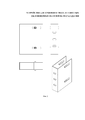
Полезная модель поясняется чертежами, на которых изображено:The utility model is illustrated by drawings, which depict:
на фиг. 1 - узел крепления направляющей с облицовочным листом к фасаду здания;in FIG. 1 - mount rail with a facing sheet to the facade of the building;
на фиг. 2 - кронштейн межэтажный;in FIG. 2 - interfloor bracket;
на фиг. 3 - крепежный элемент с пружинной защелкой,in FIG. 3 - fastener with a spring latch,
гдеWhere
1 - вертикальный направляющий (несущий) профиль;1 - vertical guide (bearing) profile;
2 - листовой материал (облицовочная панель);2 - sheet material (facing panel);
3 - кронштейн;3 - bracket;
4 - межэтажное перекрытие;4 - interfloor overlap;
5 - анкер;5 - anchor;
6 - крепежная система направляющего профиля к кронштейну;6 - mounting system of the guide profile to the bracket;
7 - регулировочный болт;7 - an adjusting bolt;
8 - пружина;8 - spring;
9 - язычок.9 - tongue.
Устройство для крепления модуля навесных облицовочных панелей на фасад здания включает модуль с облицовочными панелями, кронштейн 3, крепежную накладку 6.A device for attaching a module of hinged cladding panels to a building facade includes a module with cladding panels, a
Модуль с облицовочными панелями состоит из вертикальных направляющих профилей 1 с закрепленной на них облицовочной панелью 2. Модуль за счет наличия выреза в вертикальной направляющей 1 крепится на кронштейне 3 и удерживается на нем за счет прижимания накладкой 6.The module with cladding panels consists of vertical guide profiles 1 with a cladding panel fixed to them 2. The module, due to the presence of a cutout in the vertical guide 1, is mounted on the
Кронштейн представляет собой П-образный профиль, с наличием отверстий для крепления к фасаду здания, и наличием отверстий в боковых стенках и установкой в них, по меньшей мере, одного подвижного штифта, на который вешается и закрепляется вертикальная направляющая. Штифт выполнен в форме цилиндрического стержня длиной больше ширины кронштейна, при этом та часть стержня (центральная), которая ограничивается боковыми стенками кронштейна выполнена толщиной большей размера отверстий, куда вставлен этот стержень.The bracket is a U-shaped profile, with holes for attaching to the facade of the building, and the presence of holes in the side walls and the installation of at least one movable pin on which a vertical rail is hung and fixed. The pin is made in the form of a cylindrical rod longer than the width of the bracket, while the part of the rod (central), which is limited by the side walls of the bracket, is made of a larger thickness than the holes where this rod is inserted.
Крепежная система направляющего профиля к кронштейну представляет собой накладку с регулировочным болтом 7 с пружиной 8 и язычком 9, образующих таким образом защелку в верхней части профиля, позволяющую заменять модули без демонтажа смежных элементов. Накладка 6 располагается внутри вертикальной направляющей 1 и крепится к ней по бокам с двух сторон с помощью заклепок. В верхней части накладка ограничена площадкой, выполненной большего размера отверстия направляющей, за счет чего происходит точное позиционирование накладки в направляющей, а также защита от возможного попадания воды. В верхней площадке накладки 6 выполнено отверстие с резьбой, через которое проходит регулировочный болт 7, пружина 8 располагается в нижней части болта внутри накладки 6. Язычок 9 выполнен из цельного металла и удерживается в накладке при помощи фиксирующей шпильки с резьбой на конце, вкручивающейся в регулировочный болт. Накладка аналогично вертикальной направляющей имеет вырез для крепления к штифту кронштейна.The fastening system of the guide profile to the bracket is an overlay with an adjusting
Кронштейны 3 к фасаду здания (межэтажным перекрытиям) 4 крепятся с помощью анкеров 5, или любых аналогичных крепежных элементов.
Для установки облицовочного листа (панели) 2 в вертикальной направляющей 1 делается технологический вырез под углом 45˚, а на верхней грани листового материала 2 делается загиб полки также под углом 45˚. Полка панели заводится в соответствующий вырез в направляющей, сверху крепится уголком крепежным и механически фиксируется заклепками. К несущему профилю уголок крепежный крепится с помощью заклепок. В случае применения композитной панели снизу внешний лист металла загибается внутрь и заводится за внутренний слой металла. Также облицовочная панель (листовой материал) 2 с помощью эластичного полиуретанового клея-герметика приклеивается к вертикальной направляющей 1.To install the facing sheet (panel) 2 in the vertical guide 1, a technological cut is made at an angle of 45 °, and on the upper edge of the sheet material 2, the shelf is also bent at an angle of 45 °. The shelf of the panel is inserted into the corresponding cutout in the guide, from the top it is fastened with a corner fixing and mechanically fixed with rivets. A fixing bracket is attached to the supporting profile with rivets. In the case of using a composite panel from below, the outer sheet of metal bends inward and is wound behind the inner layer of metal. Also, the facing panel (sheet material) 2 is glued to the vertical guide 1 using elastic polyurethane adhesive-sealant.
Разработанное техническое решение предусматривает сборку готовых фасадных модулей в специальном подготовленном для этого помещении и окончательный монтаж готовых конструкций на строительной площадке.The developed technical solution provides for the assembly of finished facade modules in a special room prepared for this and the final installation of finished structures at a construction site.
К основным преимуществам данного технического решения относится:The main advantages of this technical solution include:
1. эстетичность, за счет скрытых креплений;1. aesthetics, due to hidden fixtures;
2. модульность, за счет предварительного изготовления готовых к монтажу конструкций в цеху;2. modularity, due to the preliminary manufacturing of ready-to-install structures in the workshop;
3. легкость и скорость монтажа, сокращение сроков строительства;3. ease and speed of installation, reducing construction time;
4. обеспечение пожарной безопасности.4. ensuring fire safety.
5. возможность «горячей» замены модулей без повреждения смежных конструкций.5. the possibility of "hot" replacement of modules without damage to adjacent structures.
Крепление облицовочных фасадов происходит следующим образом.Fastening of facing facades is as follows.
Модули изготавливаются в цеховых условиях, транспортируются на строительную площадку. Кронштейны крепятся к фасаду здания. На предустановленные кронштейны навешиваются готовые модули, что позволяет быстро закрывать большие площади фасадов зданий.The modules are manufactured in workshop conditions, transported to the construction site. Brackets are attached to the facade of the building. Ready-made modules are hung on the pre-installed brackets, which allows you to quickly close large areas of building facades.
Модули имеют в вертикальной направляющей вырез, за счет которого происходит установка (навешивание) модуля на штифт кронштейна. Язычок накладки при навешивании модуля вначале приподнимается, проходит штифт кронштейна и опускается, далее с помощью регулировочного болта происходит фиксирование накладки на штифте и регулирование положения направляющей.The modules have a cutout in the vertical guide, due to which the module is mounted (hung) on the bracket pin. When mounting the module, the latch tab first rises, passes the bracket pin and lowers, then, with the help of the adjustment bolt, the lining is fixed on the pin and the position of the guide is adjusted.
Для удобства монтажа и обеспечения ширины видимых межпанельных швов предусмотрены возможности регулировки модулей в нескольких плоскостях:For ease of installation and ensuring the width of visible interpanel seams, the module can be adjusted in several planes:
1. Регулировка ширины горизонтальных швов осуществляется с помощью регулировочных винтов в специальной накладке на профиль1. The width of the horizontal joints is adjusted using the adjusting screws in a special overlay on the profile
2. Регулировка в плоскости фасада осуществляется с помощью подвижных штифтов в кронштейнах.2. Adjustment in the plane of the facade is carried out using movable pins in the brackets.
Таким образом, благодаря конструкции несущего кронштейна и крепления секции возможно подгонять секции на объекте друг к другу в трех плоскостях, а в случае повреждения элемента во время эксплуатации, можно заменить модуль, не повреждая прилегающие элементы.Thus, due to the design of the supporting bracket and section fastening, it is possible to fit the sections on the object to each other in three planes, and in case of damage to the element during operation, the module can be replaced without damaging adjacent elements.
Claims (1)
Priority Applications (1)
| Application Number | Priority Date | Filing Date | Title |
|---|---|---|---|
| RU2018131544U RU186047U1 (en) | 2018-09-03 | 2018-09-03 | DEVICE FOR MOUNTING THE MODULE OF HINGED FACING PANELS TO THE BUILDING FACADE |
Applications Claiming Priority (1)
| Application Number | Priority Date | Filing Date | Title |
|---|---|---|---|
| RU2018131544U RU186047U1 (en) | 2018-09-03 | 2018-09-03 | DEVICE FOR MOUNTING THE MODULE OF HINGED FACING PANELS TO THE BUILDING FACADE |
Publications (1)
| Publication Number | Publication Date |
|---|---|
| RU186047U1 true RU186047U1 (en) | 2018-12-27 |
Family
ID=64754122
Family Applications (1)
| Application Number | Title | Priority Date | Filing Date |
|---|---|---|---|
| RU2018131544U RU186047U1 (en) | 2018-09-03 | 2018-09-03 | DEVICE FOR MOUNTING THE MODULE OF HINGED FACING PANELS TO THE BUILDING FACADE |
Country Status (1)
| Country | Link |
|---|---|
| RU (1) | RU186047U1 (en) |
Cited By (4)
| Publication number | Priority date | Publication date | Assignee | Title |
|---|---|---|---|---|
| RU2715579C1 (en) * | 2019-10-22 | 2020-03-02 | Федеральное государственное бюджетное образовательное учреждение высшего образования "Казанский государственный архитектурно-строительный университет" (КазГАСУ) | Bracket for fixing facades to intermediate floors |
| RU198382U1 (en) * | 2020-04-17 | 2020-07-02 | Евгений Юрьевич Чернышев | AGRAF FOR FASTENING THE FACING PANEL |
| CN111546819A (en) * | 2020-06-01 | 2020-08-18 | 广东茂晟广告装饰工程有限公司 | Copper art sculpture structure and installation method thereof |
| RU2772855C1 (en) * | 2021-02-25 | 2022-05-26 | Общество с ограниченной ответственностью "АРФА" | System for facing with the possibility of installing built-in lighting and profile for the system |
Citations (5)
| Publication number | Priority date | Publication date | Assignee | Title |
|---|---|---|---|---|
| DE4406930A1 (en) * | 1994-03-04 | 1995-09-07 | Manfred Klein | Connector device for supporting structure and panelling in coffer ceilings |
| RU30777U1 (en) * | 2002-12-05 | 2003-07-10 | Потапкин Сергей Иванович | Device for fixing cladding plates |
| RU2435006C1 (en) * | 2010-12-03 | 2011-11-27 | Сергей Вячеславович Архангельский | Device to attach facing panels to suspended ventilated fasade by hidden method with individual replacement of facing tiles |
| RU2514029C1 (en) * | 2012-10-25 | 2014-04-27 | Михаил Александрович Мотяев | Device to fix suspended facing panels on building facades in hidden manner |
| RU143007U1 (en) * | 2013-11-05 | 2014-07-10 | Общество с ограниченной ответственностью "ОЛМА" | DEVICE FOR FASTENING FACING ELEMENTS |
-
2018
- 2018-09-03 RU RU2018131544U patent/RU186047U1/en not_active IP Right Cessation
Patent Citations (5)
| Publication number | Priority date | Publication date | Assignee | Title |
|---|---|---|---|---|
| DE4406930A1 (en) * | 1994-03-04 | 1995-09-07 | Manfred Klein | Connector device for supporting structure and panelling in coffer ceilings |
| RU30777U1 (en) * | 2002-12-05 | 2003-07-10 | Потапкин Сергей Иванович | Device for fixing cladding plates |
| RU2435006C1 (en) * | 2010-12-03 | 2011-11-27 | Сергей Вячеславович Архангельский | Device to attach facing panels to suspended ventilated fasade by hidden method with individual replacement of facing tiles |
| RU2514029C1 (en) * | 2012-10-25 | 2014-04-27 | Михаил Александрович Мотяев | Device to fix suspended facing panels on building facades in hidden manner |
| RU143007U1 (en) * | 2013-11-05 | 2014-07-10 | Общество с ограниченной ответственностью "ОЛМА" | DEVICE FOR FASTENING FACING ELEMENTS |
Cited By (7)
| Publication number | Priority date | Publication date | Assignee | Title |
|---|---|---|---|---|
| RU2715579C1 (en) * | 2019-10-22 | 2020-03-02 | Федеральное государственное бюджетное образовательное учреждение высшего образования "Казанский государственный архитектурно-строительный университет" (КазГАСУ) | Bracket for fixing facades to intermediate floors |
| RU198382U1 (en) * | 2020-04-17 | 2020-07-02 | Евгений Юрьевич Чернышев | AGRAF FOR FASTENING THE FACING PANEL |
| CN111546819A (en) * | 2020-06-01 | 2020-08-18 | 广东茂晟广告装饰工程有限公司 | Copper art sculpture structure and installation method thereof |
| RU2772855C1 (en) * | 2021-02-25 | 2022-05-26 | Общество с ограниченной ответственностью "АРФА" | System for facing with the possibility of installing built-in lighting and profile for the system |
| RU213505U1 (en) * | 2022-05-26 | 2022-09-14 | Общество с ограниченной ответственностью "Торговая Производственная Компания ДОКСАЛ" | Means for concealed fastening of the cladding panel |
| RU2796878C1 (en) * | 2022-06-08 | 2023-05-29 | Михаил Александрович Мотяев | Hinged façade |
| RU2802637C1 (en) * | 2022-12-29 | 2023-08-30 | Федеральное государственное бюджетное образовательное учреждение высшего образования "Казанский государственный архитектурно-строительный университет" (КазГАСУ) | Assembly for fastening the guide to the bracket of the facade system |
Similar Documents
| Publication | Publication Date | Title |
|---|---|---|
| RU186047U1 (en) | DEVICE FOR MOUNTING THE MODULE OF HINGED FACING PANELS TO THE BUILDING FACADE | |
| RU178134U1 (en) | Device for attaching small-sized elements of the curtain wall facade, preferably facing brick | |
| US20190063064A1 (en) | Thermal and acoustic insulating and sealing means for a safing slot in a curtain wall | |
| RU2339775C1 (en) | Face plate attachment method | |
| RU2448223C1 (en) | Wall heat insulation panel with ventilated facade of operational compatibility "roslav" and support bracket for its installation | |
| RU2641140C1 (en) | Hinge system of lining of buildings and premises, including for building partitions | |
| RU2609503C1 (en) | Facade cladding system using metal cassettes | |
| KR102039324B1 (en) | Fireproof partition structure and its construction method | |
| RU186046U1 (en) | DESIGN OF THE MODULE OF HINGED FACING PANELS | |
| RU2180935C2 (en) | Tool for fastening facing plates | |
| RU85519U1 (en) | DEVICE FOR FIXING FACING TILES | |
| PL421761A1 (en) | System for fixing panels on buildings' facades | |
| RU67134U1 (en) | DEVICE FOR FASTENING FRONT PLATES | |
| RU113286U1 (en) | FACING PANEL, INSTALLATION ELEMENT FOR FACING PANEL AND WALL FACING SYSTEM | |
| RU138890U1 (en) | FACADE Hinged Ventilated Building Fencing | |
| RU2307906C2 (en) | Method for vented building face assemblage and enveloping structure for method realization | |
| RU102646U1 (en) | WALL HEAT-INSULATING PANEL WITH VENTILATED FACADE OF FACTORY READINESS "ROSLAV" AND SUPPORT BRACKET FOR ITS INSTALLATION | |
| JP2018009383A (en) | Fixing hardware for fixing exterior wall panel | |
| RU2791843C1 (en) | System for fastening the cladding of the hinged facade system | |
| RU69114U1 (en) | FACADE BRACKET FOR FASTENING HINGED PANELS FOR FACING BUILDINGS | |
| RU2416009C1 (en) | Systems of suspended facades and methods of assembly (versions) | |
| JP7074980B2 (en) | How to install the partition for the balcony | |
| RU2761224C1 (en) | Method for installing facing elements on the bearing surface (variants) and surface facing | |
| RU48193U1 (en) | SIAL VENTILATED FACADES SYSTEM (OPTIONS) | |
| RU2815672C1 (en) | Facade cladding fastening system |
Legal Events
| Date | Code | Title | Description |
|---|---|---|---|
| MM9K | Utility model has become invalid (non-payment of fees) |
Effective date: 20190904 |