RU133028U1 - SURFACE CLEANING DEVICE (OPTIONS) - Google Patents
SURFACE CLEANING DEVICE (OPTIONS) Download PDFInfo
- Publication number
- RU133028U1 RU133028U1 RU2013126169/05U RU2013126169U RU133028U1 RU 133028 U1 RU133028 U1 RU 133028U1 RU 2013126169/05 U RU2013126169/05 U RU 2013126169/05U RU 2013126169 U RU2013126169 U RU 2013126169U RU 133028 U1 RU133028 U1 RU 133028U1
- Authority
- RU
- Russia
- Prior art keywords
- scraper
- nozzle
- spray head
- base
- inclination
- Prior art date
Links
- 238000004140 cleaning Methods 0.000 title claims abstract description 58
- 239000007921 spray Substances 0.000 claims abstract description 76
- 239000007788 liquid Substances 0.000 claims abstract description 22
- 239000012530 fluid Substances 0.000 claims abstract description 10
- 230000001154 acute effect Effects 0.000 claims abstract description 8
- 230000015572 biosynthetic process Effects 0.000 claims abstract description 8
- 238000005086 pumping Methods 0.000 claims description 8
- 238000005406 washing Methods 0.000 description 15
- 230000005611 electricity Effects 0.000 description 3
- XLYOFNOQVPJJNP-UHFFFAOYSA-N water Substances O XLYOFNOQVPJJNP-UHFFFAOYSA-N 0.000 description 3
- 239000012459 cleaning agent Substances 0.000 description 2
- 239000011521 glass Substances 0.000 description 2
- 239000003795 chemical substances by application Substances 0.000 description 1
- 238000004891 communication Methods 0.000 description 1
- 239000000356 contaminant Substances 0.000 description 1
- 239000013013 elastic material Substances 0.000 description 1
- 239000012535 impurity Substances 0.000 description 1
- 238000000034 method Methods 0.000 description 1
- 238000005507 spraying Methods 0.000 description 1
- 230000007704 transition Effects 0.000 description 1
Images
Landscapes
- Cleaning By Liquid Or Steam (AREA)
Abstract
1. Устройство для очистки поверхностей, содержащее пустотелое основание удлиненной формы, полость которого образует резервуар для очищающей жидкости, распылительное устройство, включающее насосное устройство, управляющий нажимной крючок и распылительную головку с соплом, а также чистящий элемент, выполненный в виде плоского скребка удлиненной формы, установленного в держателе скребка, причем распылительная головка с соплом и управляющий нажимной крючок размещены с одной стороны устройства под держателем скребка, который расположен в устройстве с наклоном таким образом, что при вертикальном положении устройства скребок располагается над и впереди сопла распылительной головки, отличающееся тем, что держатель скребка и распылительное устройство жестко соединены с основанием устройства, в стенке которого образовано сквозное отверстие, предназначенное для заполнения резервуара очищающей жидкостью, при этом наклон плоскости скребка и наклон оси сопла распылительной головки ориентированы под острым углом к очищаемой поверхности.2. Устройство по п.1, отличающееся тем, что угол наклона оси сопла распылительной головки к продольной оси основания устройства предпочтительно составляет 25-50°.3. Устройство по п.1, отличающееся тем, что угол наклона плоскости скребка к продольной оси основания устройства предпочтительно составляет 25-50°.4. Устройство по п.1, отличающееся тем, что расстояние от выходного среза сопла до кромки скребка предпочтительно равно 80-180 мм.5. Устройство по п.1, отличающееся тем, что сопло распылительной головки выполнено в виде узкой плоской щели для возможности образования веерообразной стру�1. A device for cleaning surfaces containing a hollow base of elongated shape, the cavity of which forms a reservoir for cleaning liquid, a spray device including a pump device, a control hook and a spray head with a nozzle, and a cleaning element made in the form of a flat scraper of an elongated shape, installed in the scraper holder, the spray head with the nozzle and the control pressure hook placed on one side of the device under the scraper holder, which is located in device with an inclination so that when the device is upright, the scraper is located above and in front of the nozzle of the spray head, characterized in that the scraper holder and spray device are rigidly connected to the base of the device, in the wall of which there is a through hole designed to fill the tank with cleaning fluid, the inclination of the plane of the scraper and the inclination of the axis of the nozzle of the spray head are oriented at an acute angle to the surface being cleaned. 2. The device according to claim 1, characterized in that the angle of inclination of the axis of the nozzle of the spray head to the longitudinal axis of the base of the device is preferably 25-50 °. 3. The device according to claim 1, characterized in that the angle of inclination of the plane of the scraper to the longitudinal axis of the base of the device is preferably 25-50 °. The device according to claim 1, characterized in that the distance from the exit nozzle exit to the edge of the scraper is preferably 80-180 mm. The device according to claim 1, characterized in that the nozzle of the spray head is made in the form of a narrow flat slit for the possibility of the formation of a fan-shaped jet
Description
Полезная модель относится к устройствам для очистки поверхностей, преимущественно наружных поверхностей транспортных средств.The utility model relates to devices for cleaning surfaces, mainly the outer surfaces of vehicles.
Широко известен способ очистки стекол и зеркал с применением двух отдельных устройств: бутылка с очищающей жидкостью и распылителем и водосгон с ручкой и наконечником. Для очистки загрязненной поверхности предварительно распыляют жидкость на очищаемой поверхности, а затем посредством водосгона производят очистку поверхности.The method of cleaning glasses and mirrors using two separate devices is widely known: a bottle with a cleaning liquid and a spray and a water squeegee with a handle and a tip. To clean a contaminated surface, the liquid is first sprayed onto the surface to be cleaned, and then the surface is cleaned by means of a water pump.
Известно устройство для очистки стекол, состоящее из рукоятки со встроенным клапаном для подачи моющей жидкости и моющего элемента, расположенного в держателе, связанном с рукояткой и выполненным в виде согнутого эластичного бруска, при этом устройство снабжено перфорированной трубкой, расположенной в сгибе бруска и соединенной с рукояткой, а держатель представляет собой конусообразный кожух, в вершине которого выполнено отверстие для ввода конца рукоятки (а.с. СССР №456608, МПК A47L 1/10, публикация 1975 г.).A device for cleaning glass, consisting of a handle with a built-in valve for supplying washing liquid and a washing element located in the holder associated with the handle and made in the form of a bent elastic bar, the device is equipped with a perforated tube located in the bend of the bar and connected to the handle , and the holder is a cone-shaped casing, at the top of which a hole is made for entering the end of the handle (AS USSR No. 456608, IPC
Недостатками известного устройства является достаточно сложная конструкция моющего элемента и необходимость внешнего источника для принудительной подачи моющей жидкости к моющему элементу.The disadvantages of the known device is the rather complicated design of the washing element and the need for an external source for the forced supply of washing liquid to the washing element.
Известно портативное устройство для мойки наружной поверхности транспортных средств, включающее корпус с рукояткой пистолетного типа, снабженной электровыключателем, размещенный внутри корпуса насос, со встроенным электроприводом, имеющим возможность подключения с помощью внешнего электрического провода к внешнему источнику электроэнергии (патент РФ №38141, МПК B60S 3/04, публикация 2003 г.).A portable device for washing the outer surface of vehicles is known, including a housing with a pistol grip, equipped with an electric switch, a pump located inside the housing, with a built-in electric drive that can be connected using an external electric wire to an external source of electricity (RF patent No. 38141, IPC B60S 3 / 04, 2003 publication).
Недостатком известного устройства является его сложность и необходимость наличия внешнего источника электроэнергии.A disadvantage of the known device is its complexity and the need for an external source of electricity.
Известно переносное устройство для влажной чистки наружной поверхности транспортных средств, включающее канистру, снабженную ручкой и крышкой в верхней части, размещенный внутри канистры водяной погружной насос, со встроенным электроприводом, имеющим возможность подключения с помощью внешнего электрического провода к внешнему источнику электроэнергии (патент РФ №31543, B60S 3/04, публикация 2003 г.).A portable device for wet cleaning the outer surface of vehicles is known, including a canister equipped with a handle and a lid in the upper part, a water submersible pump located inside the canister, with a built-in electric drive having the ability to connect using an external electric wire to an external source of electricity (RF patent No. 31543 , B60S 3/04, 2003 publication).
Недостатком известного устройства является его сложность, громоздкость, необходимость наличия внешнего источника для принудительной подачи моющей жидкости к моющему элементу.A disadvantage of the known device is its complexity, bulkiness, the need for an external source for the forced supply of washing liquid to the washing element.
Известно устройство для очистки от загрязнений поверхности транспортных средств, для мытья остекленных поверхностей окон квартир и офисов, содержащее моющий элемент, например щетку, источник давления, выполненный из эластичного материала и клапан подачи раствора на моющий элемент, при этом устройство снабжено дополнительным клапаном, установленным на входе моющей жидкости в трубопровод, источник давления расположен между двумя клапанами и сообщен с трубопроводом отверстиями, клапан подачи раствора на моющий элемент выполнен в виде шарика, ход которого ограничен со стороны источника давления седлом, а со стороны моющего элемента ограничительной втулкой с щелевыми пазами в осевом направлении (патент РФ №2128089, МПК B60S 3/04; A 4711/00, публикация 1999 г.).A device for cleaning from pollution of the surface of vehicles, for washing glazed surfaces of windows of apartments and offices, containing a washing element, for example a brush, a pressure source made of elastic material and a solution supply valve to the washing element, the device is equipped with an additional valve mounted on the inlet of the washing liquid into the pipeline, the pressure source is located between the two valves and is in communication with the pipeline holes, the valve for supplying the solution to the washing element is made in the form of rica, whose stroke is limited by the seat of the pressure source, and from the cleaning member bounding sleeve with slotted grooves in the axial direction (RF patent №2128089, IPC
Недостатком известного устройства является его неэффективность при очистки наружных поверхностей транспортных средств от различных загрязнений.A disadvantage of the known device is its inefficiency in cleaning the outer surfaces of vehicles from various contaminants.
Известно устройство для очистки окон немецкой фирмы LEIFHEIT AG, содержащее основание, полость которого образует резервуар для очищающей жидкости, распылительный механизм, включающий насосное устройство, управляющий нажимной рычаг и распылительную головку с соплом, а также чистящее средство, выполненное в виде плоского скребка удлиненной формы, установленного в держателе, при этом распылительная головка с соплом и управляющий нажимной рычаг расположены на противоположных сторонах устройства (европейский патент №1872701, МПК A47L 1/06, публикация 2008 г.).A device for cleaning windows of the German company LEIFHEIT AG is known, comprising a base, the cavity of which forms a reservoir for the cleaning liquid, a spray mechanism including a pump device, a control lever and a spray head with a nozzle, as well as a cleaning agent made in the form of an elongated flat scraper, installed in the holder, while the spray head with the nozzle and the control pressure lever are located on opposite sides of the device (European patent No. 1872701, IPC
Известно также устройство для очистки различных поверхностей, содержащее основание, полость которого образует резервуар для очищающей жидкости, распылительный механизм, включающий насосное устройство, управляющий нажимной крючок и распылительную головку с соплом, а также чистящее средство, выполненное в виде плоского скребка удлиненной формы, установленного в держателе, причем держатель скребка расположен в устройстве таким образом, что при вертикальном положении устройства скребок располагается над и впереди сопла распылительной головки. Наклон плоскости скребка и наклон оси сопла распылительной головки ориентированы под прямым углом к очищаемой поверхности (патент США №6223380, МПК A47L 1/08, публикация 2001 г. - прототип).Also known is a device for cleaning various surfaces, containing a base, the cavity of which forms a reservoir for the cleaning liquid, a spray mechanism including a pump device, a control hook and a spray head with a nozzle, and a cleaning agent made in the form of an elongated flat scraper installed in holder, and the scraper holder is located in the device so that when the device is upright, the scraper is located above and in front of the spray nozzle olovki. The inclination of the plane of the scraper and the inclination of the axis of the nozzle of the spray head are oriented at right angles to the surface being cleaned (US patent No. 6223380, IPC
Технической задачей предложенных вариантов устройства является повышение эффективности очистки загрязненных поверхностей с помощью устройства, а также повышение удобства его эксплуатации.The technical task of the proposed device options is to increase the efficiency of cleaning contaminated surfaces using the device, as well as increasing the convenience of its operation.
Технический результат заключается в создании устройства, обеспечивающего удобную для пользователя эффективную очистку загрязненной поверхности.The technical result consists in the creation of a device that provides a user-friendly efficient cleaning of a contaminated surface.
Предложенные варианты устройства расширяют арсенал технических средств, используемых для очистки наружных поверхностей транспортных средств от загрязнений.The proposed device options expand the arsenal of technical means used to clean the outer surfaces of vehicles from pollution.
Сущность предложенного технического решения заключается в следующем.The essence of the proposed technical solution is as follows.
Устройство для очистки поверхностей содержит пустотелое основание удлиненной формы, полость которого образует резервуар для очищающей жидкости, распылительное устройство, включающее насосное устройство, управляющий нажимной крючок и распылительную головку с соплом, а также чистящий элемент, выполненный в виде плоского скребка удлиненной формы, установленного в держателе скребка. Распылительная головка с соплом и управляющий нажимной крючок размещены с одной стороны устройства под держателем скребка, который расположен в устройстве с наклоном таким образом, что при вертикальном положении устройства скребок располагается над и впереди сопла распылительной головки. Держатель скребка и распылительное устройство жестко соединены с основанием устройства, при этом наклон плоскости скребка и наклон оси сопла распылительной головки ориентированы под острым углом к очищаемой поверхности. В стенке основания устройства образовано сквозное отверстие, предназначенное для заполнения резервуара очищающей жидкостью.The surface cleaning device comprises an elongated hollow base, the cavity of which forms a reservoir for the cleaning liquid, a spray device including a pump device, a control hook and a spray head with a nozzle, and a cleaning element made in the form of an elongated flat scraper installed in the holder scraper. The spray head with the nozzle and the control pressure hook are placed on one side of the device under the scraper holder, which is inclined in the device so that when the device is upright, the scraper is located above and in front of the spray head nozzle. The scraper holder and the spray device are rigidly connected to the base of the device, while the inclination of the plane of the scraper and the inclination of the axis of the nozzle of the spray head are oriented at an acute angle to the surface being cleaned. A through hole is formed in the wall of the base of the device, designed to fill the tank with cleaning fluid.
Угол наклона оси сопла распылительной головки к продольной оси основания устройства предпочтительно составляет 25°-50°.The angle of inclination of the axis of the nozzle of the spray head to the longitudinal axis of the base of the device is preferably 25 ° -50 °.
Угол наклона плоскости скребка к продольной оси основания устройства предпочтительно составляет 25°-50°.The angle of inclination of the plane of the scraper to the longitudinal axis of the base of the device is preferably 25 ° -50 °.
Расстояние от выходного среза сопла до кромки скребка предпочтительно равно 80-180 мм.The distance from the nozzle exit to the edge of the scraper is preferably 80-180 mm.
Сопло распылительной головки может быть выполнено в виде узкой плоской щели для возможности образования веерообразной струи очищающей жидкости.The nozzle of the spray head can be made in the form of a narrow flat slit to allow the formation of a fan-shaped jet of cleaning fluid.
Насосное устройство содержит соединенный с управляющим нажимным крючком подпружиненный поршень, размещенный в цилиндре, сообщенном с одной стороны с резервуаром для очищающей жидкости посредством заборной трубки, пропущенной через стенку основания, а с другой стороны соединенным с распылительной головкой.The pump device comprises a spring-loaded piston connected to the control pressure hook, located in a cylinder connected on one side to the cleaning fluid reservoir by means of a suction tube passed through the base wall and, on the other hand, connected to the spray head.
Основание может быть образовано в виде ручки-емкости.The base can be formed in the form of a handle-container.
В стенке верхней части основания выполнено сквозное отверстие, в которое герметично встроен воздушный клапан.A through hole is made in the wall of the upper part of the base into which the air valve is hermetically integrated.
Скребок чистящего элемента может быть выполнен съемным и закреплен в держателе с возможностью замены.The scraper of the cleaning element can be removable and fixed in the holder with the possibility of replacement.
В другом варианте исполнения устройство для очистки поверхностей содержит пустотелое основание удлиненной формы, полость которого образует резервуар для очищающей жидкости, распылительное устройство, включающее насосное устройство, управляющий нажимной крючок и распылительную головку с соплом, а также чистящий элемент, выполненный в виде плоского скребка удлиненной формы, установленного в держателе. Распылительная головка с соплом и управляющий нажимной крючок размещены с одной стороны устройства под держателем скребка, который расположен в устройстве с наклоном таким образом, что при вертикальном положении устройства скребок располагается над и впереди сопла распылительной головки. Держатель скребка и распылительное устройство соединены с основанием посредством переходного соединительного устройства, при этом наклон плоскости скребка и наклон оси сопла распылительной головки ориентированы под острым углом к очищаемой поверхности.In another embodiment, the surface cleaning device comprises an elongated hollow base, the cavity of which forms a reservoir for the cleaning liquid, a spray device comprising a pump device, a control hook and a spray head with a nozzle, and a cleaning element made in the form of an elongated flat scraper installed in the holder. The spray head with the nozzle and the control pressure hook are placed on one side of the device under the scraper holder, which is inclined in the device so that when the device is upright, the scraper is located above and in front of the spray head nozzle. The scraper holder and the spray device are connected to the base via a transitional connecting device, while the inclination of the plane of the scraper and the inclination of the axis of the nozzle of the spray head are oriented at an acute angle to the surface being cleaned.
Угол наклона оси сопла распылительной головки к продольной оси основания устройства предпочтительно составляет 25°-50°.The angle of inclination of the axis of the nozzle of the spray head to the longitudinal axis of the base of the device is preferably 25 ° -50 °.
Угол наклона плоскости скребка к продольной оси основания устройства предпочтительно составляет 25°-50°.The angle of inclination of the plane of the scraper to the longitudinal axis of the base of the device is preferably 25 ° -50 °.
Расстояние от выходного среза сопла до кромки скребка предпочтительно равно 80-180 мм.The distance from the nozzle exit to the edge of the scraper is preferably 80-180 mm.
Сопло распылительной головки может быть выполнено в виде узкой плоской щели для возможности образования веерообразной струи очищающей жидкости.The nozzle of the spray head can be made in the form of a narrow flat slit to allow the formation of a fan-shaped jet of cleaning fluid.
Насосное устройство содержит соединенный с управляющим нажимным крючком подпружиненный поршень, размещенный в цилиндре, сообщенном с одной стороны с резервуаром для очищающей жидкости посредством заборной трубки, а с другой стороны соединенным с распылительной головкой.The pump device comprises a spring-loaded piston connected to the control pressure hook, located in a cylinder connected on one side to the cleaning liquid reservoir by means of an intake pipe, and on the other hand connected to the spray head.
Насосное устройство может быть закреплено непосредственно на держателе скребка.The pump device can be mounted directly on the scraper holder.
Насосное устройство может быть закреплено непосредственно на переходном соединительном устройстве, при этом держатель скребка и цилиндр насосного устройства могут быть соединены шарнирно друг с другом с возможностью поворота держателя скребка вокруг оси соединяющего их шарнира.The pump device can be mounted directly on the transitional connecting device, while the scraper holder and the cylinder of the pumping device can be hinged to each other with the possibility of rotation of the scraper holder around the axis of the joint connecting them.
Скребок чистящего элемента может быть выполнен съемным и закреплен в держателе с возможностью замены.The scraper of the cleaning element can be removable and fixed in the holder with the possibility of replacement.
Основание может быть образовано в виде ручки-емкости.The base can be formed in the form of a handle-container.
Основание может быть выполнено в виде стандартной пластиковой бутылки.The base can be made in the form of a standard plastic bottle.
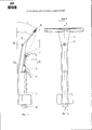
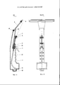
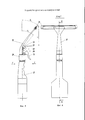
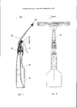
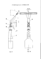
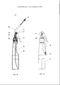
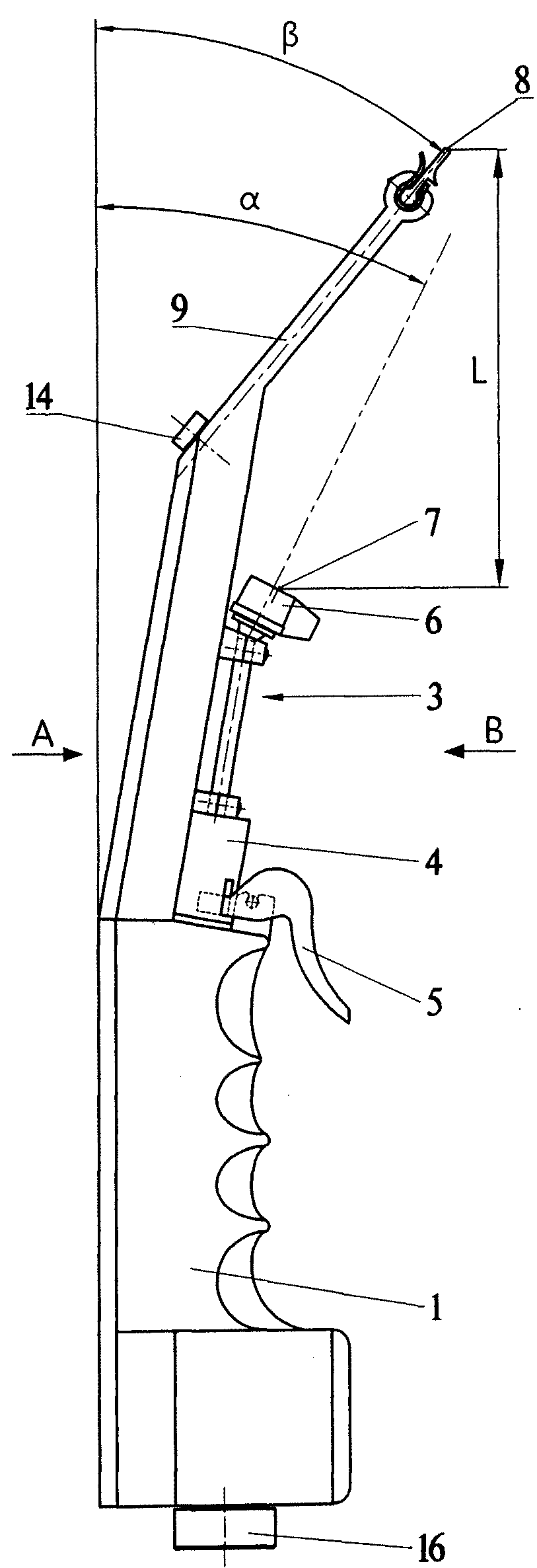
Заявляемая полезная модель представлена на чертежах, где на фиг.1 изображено устройство для очистки поверхностей (1-ый вариант); на фиг.2 вид А на фиг.1 (вид в плане); на фиг.3 - разрез ББ на фиг.2; на фиг.4 - вид В на фиг.1; на фиг.5 - устройство для очистки поверхностей (2-й вариант); на фиг.6 - вид Г на фиг.5; на фиг.7 - разрез ДД на фиг.6; на фиг.8 вид Ε на фиг.7; на фиг.9 - устройство для очистки поверхностей; на фиг.10 - вид Ж на фиг.9; на фиг.11 - разрез ЗЗ на фиг.10; на фиг.12 - устройство на фиг.9 в сложенном состоянии.The inventive utility model is presented in the drawings, where Fig. 1 shows a device for cleaning surfaces (1st option); figure 2 view a in figure 1 (view in plan); figure 3 - section BB in figure 2; figure 4 is a view In figure 1; figure 5 - a device for cleaning surfaces (2nd option); figure 6 is a view of figure 5; Fig.7 is a section of DD in Fig.6; in Fig.8 view Ε in Fig.7; figure 9 is a device for cleaning surfaces; figure 10 is a view W in figure 9; figure 11 is a section of the ЗЗ in figure 10; in Fig.12 - the device of Fig.9 in the folded state.
Устройство для очистки поверхностей по 1-му варианту содержит пустотелое удлиненное основание 1, полость которого образует резервуар 2 для очищающей жидкости, распылительное устройство 3, включающее насосное устройство 4, управляющий нажимной крючок 5 и распылительную головку 6 с соплом 7.The device for cleaning surfaces according to the first embodiment comprises a hollow
Основание 1 образовано в виде ручки-емкости.The
Устройство содержит также чистящий элемент, выполненный в виде плоского скребка 8 удлиненной формы, установленного в держателе 9.The device also contains a cleaning element made in the form of a
Держатель 9 скребка расположен в устройстве таким образом, что при вертикальном положении устройства скребок 8 располагается над и впереди сопла 7 распылительной головки.The
Скребок 8 чистящего элемента может быть выполнен съемным и закреплен в держателе с возможностью замены (не показано).The
Держатель 9 скребка 8 и распылительное устройство 3 жестко соединены с основанием 1 устройства.The
Наклон плоскости скребка 8 и наклон оси сопла 7 распылительной головки ориентированы под острым углом к очищаемой поверхности, что обеспечивается конструктивным расположением держателя 9 и распылительной головки 6 с соплом 7 относительно продольной оси основания 1 устройства.The inclination of the plane of the
Угол «α» наклона оси сопла 7 к продольной оси основания устройства, равный углу наклон оси сопла 7 распылительной головки к очищаемой поверхности при расположении основания 1 устройства параллельно относительно очищаемой поверхности, предпочтительно составляет 25°-50°.The angle "α" of the axis of the
Угол «β» наклона плоскости скребка 8 к продольной оси основания 1 устройства предпочтительно составляет 25°-50°.The angle β of inclination of the plane of the
Расстояние L от выходного среза сопла 7 до рабочей кромки скребка 8 предпочтительно равно 80-180 мм.The distance L from the exit section of the
Для возможности образования веерообразной струи очищающей жидкости сопло 7 распылительной головки 6 может быть выполнено в виде узкой плоской щели.To allow the formation of a fan-shaped jet of cleaning liquid, the
Распылительная головка 6 может быть выполнена с возможностью перекрытия сопла 7 посредством запорного механизма (не показано).The
Насосное устройство 4 содержит подпружиненный поршень 10, размещенный в цилиндре 11, который сообщен, с одной стороны, с резервуаром 2 посредством заборной трубки 12, пропущенной через стенку основания 1, а с другой стороны соединен с распылительной головкой 6.The
В стенке верхней части основания 1 выполнено сквозное отверстие 13, в которое герметично встроен воздушный клапан 14, препятствующий образованию пониженного давления в резервуаре 2 при работе насосного устройства.A through
В стенке нижней части основания 1 выполнено сквозное отверстие 15, через которое в устройство заливается очищающая жидкость. Отверстие 15 закрыто резьбовой крышкой 16.A through
Устройство для очистки поверхностей по 2-му варианту содержит пустотелое удлиненное основание 17, полость которого образует резервуар 18 для очищающей жидкости, распылительное устройство 19, включающее насосное устройство 20, управляющий нажимной крючок 21 и распылительную головку 22 с соплом 23.The surface cleaning device according to the 2nd embodiment comprises a hollow
Основание 17 образовано в виде ручки-емкости.The
Устройство содержит также чистящий элемент, выполненный в виде плоского скребка 24 удлиненной формы, установленного в держателе 25. Держатель 25 скребка расположен в устройстве таким образом, что при вертикальном положении устройства скребок 24 располагается над и впереди сопла 23 распылительной головки.The device also includes a cleaning element made in the form of an elongated
Скребок 24 чистящего элемента может быть выполнен съемным и закреплен в держателе с возможностью замены (не показано).The
Держатель 25 скребка 24 жестко соединен с распылительным устройством 19, которое в свою очередь соединено с основанием посредством переходного устройства.The
Наклон плоскости скребка 24 и наклон оси сопла 23 распылительной головки ориентированы под острым углом к очищаемой поверхности, что обеспечивается конструктивным расположением держателя 25 и распылительной головки 22 с соплом 23 относительно продольной оси основания 17 устройства.The inclination of the plane of the
Угол «α1» наклона оси сопла 23 к продольной оси основания 17 устройства, равный углу наклон оси сопла распылительной головки к очищаемой поверхности при расположении основания 17 устройства параллельно относительно очищаемой поверхности, предпочтительно составляет 25°-50°.The angle "α 1 " of the axis of the
Угол «β1» наклона плоскости скребка 24 к продольной оси основания 17 устройства предпочтительно составляет 25°-50°.The angle "β 1 " of the plane of the
Расстояние L1 от выходного среза сопла 23 до рабочей кромки скребка 24 предпочтительно равно 80-180 мм.The distance L 1 from the exit section of the
Сопло 23 распылительной головки может быть выполнено в виде узкой плоской щели для возможности образования веерообразной струи очищающей жидкости.The
Распылительная головка 22 может быть выполнена с возможностью перекрытия сопла 23 посредством запорного механизма (не показано).The
Насосное устройство 20 содержит подпружиненный поршень 27, размещенный в цилиндре 28, который сообщен, с одной стороны, с резервуаром 18 посредством заборной трубки 29, а с другой стороны соединен с распылительной головкой 22.The
На фиг.5-8 показано устройство с держателем 25 скребка, жестко соединенным с распылительным устройством.Figure 5-8 shows a device with a
На фиг.9-11 показано устройство с держателем 30 скребка, шарнирно закрепленным на распылительном устройстве с возможностью поворота держателя скребка вокруг оси соединяющего их шарнира 31.Figures 9-11 show a device with a
Данное конструктивное решение позволяет уменьшить габариты устройства в нерабочем состоянии.This design solution allows to reduce the dimensions of the device inoperative.
Для очистки загрязненной поверхности устройство удерживают в руке и располагают устройство параллельно очищаемой поверхности (скребок располагается вверху). При нажатии пальцем на крючок моющая жидкость (моющий раствор) с помощью насосного устройства поступает из резервуара в сопло распылительного устройства, посредством которого наносится на очищаемую поверхность в плоскости скребка и непосредственно перед ним. Поскольку жидкость распыляется под острым углом к поверхности, обеспечивается более качественный смыв струей жидкости загрязнений с очищаемой поверхности. При прижатии кромки скребка к поверхности и перемещении скребка вдоль нее происходит очистка поверхности.To clean the contaminated surface, the device is held in the hand and the device is placed parallel to the surface being cleaned (the scraper is located at the top). When a finger is pressed on the hook, the washing liquid (washing solution) by means of a pumping device enters from the reservoir into the nozzle of the spraying device, by means of which it is applied to the surface to be cleaned in the plane of the scraper and immediately in front of it. Since the liquid is sprayed at an acute angle to the surface, a better wash-off of the impurities from the surface being cleaned is provided by the liquid stream. When pressing the edge of the scraper to the surface and moving the scraper along it, the surface is cleaned.
Предложенное устройство может быть использовано как в его вертикальном положении, так и почти в горизонтальном положении.The proposed device can be used both in its vertical position and in almost horizontal position.
Данное техническое решение обеспечивает удобную для пользователя эффективную очистку загрязненной поверхности.This technical solution provides a user-friendly efficient cleaning of contaminated surfaces.
Claims (23)
Priority Applications (1)
| Application Number | Priority Date | Filing Date | Title |
|---|---|---|---|
| RU2013126169/05U RU133028U1 (en) | 2013-06-07 | 2013-06-07 | SURFACE CLEANING DEVICE (OPTIONS) |
Applications Claiming Priority (1)
| Application Number | Priority Date | Filing Date | Title |
|---|---|---|---|
| RU2013126169/05U RU133028U1 (en) | 2013-06-07 | 2013-06-07 | SURFACE CLEANING DEVICE (OPTIONS) |
Publications (1)
| Publication Number | Publication Date |
|---|---|
| RU133028U1 true RU133028U1 (en) | 2013-10-10 |
Family
ID=49303224
Family Applications (1)
| Application Number | Title | Priority Date | Filing Date |
|---|---|---|---|
| RU2013126169/05U RU133028U1 (en) | 2013-06-07 | 2013-06-07 | SURFACE CLEANING DEVICE (OPTIONS) |
Country Status (1)
| Country | Link |
|---|---|
| RU (1) | RU133028U1 (en) |
Cited By (3)
| Publication number | Priority date | Publication date | Assignee | Title |
|---|---|---|---|---|
| RU167506U1 (en) * | 2016-04-18 | 2017-01-10 | Ваагн Энгерфеевич Памбухчян | Surface Cleaner |
| RU2627278C2 (en) * | 2014-10-30 | 2017-08-04 | Фискарс Финланд Ой Аб | Ice scraper |
| RU2813039C1 (en) * | 2023-08-07 | 2024-02-06 | Публичное акционерное общество "Татнефть" имени В.Д. Шашина | Scraper device for cleaning containers from oil residues |
-
2013
- 2013-06-07 RU RU2013126169/05U patent/RU133028U1/en not_active IP Right Cessation
Cited By (4)
| Publication number | Priority date | Publication date | Assignee | Title |
|---|---|---|---|---|
| RU2627278C2 (en) * | 2014-10-30 | 2017-08-04 | Фискарс Финланд Ой Аб | Ice scraper |
| US9855927B2 (en) | 2014-10-30 | 2018-01-02 | Fiskars Garden Oy Ab | Ice scraper |
| RU167506U1 (en) * | 2016-04-18 | 2017-01-10 | Ваагн Энгерфеевич Памбухчян | Surface Cleaner |
| RU2813039C1 (en) * | 2023-08-07 | 2024-02-06 | Публичное акционерное общество "Татнефть" имени В.Д. Шашина | Scraper device for cleaning containers from oil residues |
Similar Documents
| Publication | Publication Date | Title |
|---|---|---|
| KR101591948B1 (en) | Window Cleaner | |
| CN104958051A (en) | Glass scraping device | |
| US2436454A (en) | Self-contained window cleaning implement | |
| CN203873703U (en) | Electric liquid spraying and wiping cleaner | |
| US6082915A (en) | Liquid filled squeegee for side view mirror | |
| WO2016192343A1 (en) | Multifunctional water spray mop | |
| CN110448388B (en) | Portable mouth cleaner | |
| CN102197974A (en) | Glass cleaner | |
| WO2014196900A1 (en) | Surface-cleaning device (variants) | |
| CN202086415U (en) | Glass cleaning device | |
| CN211303453U (en) | A hotel with warm light type shower head | |
| CN210230756U (en) | A cleaning mechanism for a filling machine | |
| CN203195598U (en) | Window wiper with water being convenient to spray | |
| CN211749271U (en) | High-rise glass window cleaning device | |
| RU135595U1 (en) | SURFACE WASHER | |
| CN108969122A (en) | Cleaning device is used in a kind of maintenance of orthopaedic drill | |
| CN219923877U (en) | Glass cleaning structure | |
| CN208081164U (en) | A kind of cleaning vehicle with dust-absorbing function | |
| CN216652156U (en) | Convenient integrative window-cleaning watering can | |
| CN211330363U (en) | Cleaning device | |
| RU167506U1 (en) | Surface Cleaner | |
| CN214077350U (en) | Cleaning agent spraying gun for cleaning range hood | |
| CN210784150U (en) | Cleaning tool | |
| CN204318649U (en) | A kind of hand-held hydrojet window washer | |
| CN221013096U (en) | Glass cleaning device |
Legal Events
| Date | Code | Title | Description |
|---|---|---|---|
| MM1K | Utility model has become invalid (non-payment of fees) |
Effective date: 20150608 |