KR950004606B1 - Condition adaptive-type control method for internal combustion engine - Google Patents
Condition adaptive-type control method for internal combustion engine Download PDFInfo
- Publication number
- KR950004606B1 KR950004606B1 KR1019870004321A KR870004321A KR950004606B1 KR 950004606 B1 KR950004606 B1 KR 950004606B1 KR 1019870004321 A KR1019870004321 A KR 1019870004321A KR 870004321 A KR870004321 A KR 870004321A KR 950004606 B1 KR950004606 B1 KR 950004606B1
- Authority
- KR
- South Korea
- Prior art keywords
- control
- vehicle
- driver
- state
- speed
- Prior art date
Links
Images


Classifications
-
- F—MECHANICAL ENGINEERING; LIGHTING; HEATING; WEAPONS; BLASTING
- F02—COMBUSTION ENGINES; HOT-GAS OR COMBUSTION-PRODUCT ENGINE PLANTS
- F02D—CONTROLLING COMBUSTION ENGINES
- F02D41/00—Electrical control of supply of combustible mixture or its constituents
- F02D41/02—Circuit arrangements for generating control signals
- F02D41/14—Introducing closed-loop corrections
- F02D41/1497—With detection of the mechanical response of the engine
-
- F—MECHANICAL ENGINEERING; LIGHTING; HEATING; WEAPONS; BLASTING
- F02—COMBUSTION ENGINES; HOT-GAS OR COMBUSTION-PRODUCT ENGINE PLANTS
- F02D—CONTROLLING COMBUSTION ENGINES
- F02D41/00—Electrical control of supply of combustible mixture or its constituents
- F02D41/02—Circuit arrangements for generating control signals
- F02D41/04—Introducing corrections for particular operating conditions
-
- B—PERFORMING OPERATIONS; TRANSPORTING
- B60—VEHICLES IN GENERAL
- B60K—ARRANGEMENT OR MOUNTING OF PROPULSION UNITS OR OF TRANSMISSIONS IN VEHICLES; ARRANGEMENT OR MOUNTING OF PLURAL DIVERSE PRIME-MOVERS IN VEHICLES; AUXILIARY DRIVES FOR VEHICLES; INSTRUMENTATION OR DASHBOARDS FOR VEHICLES; ARRANGEMENTS IN CONNECTION WITH COOLING, AIR INTAKE, GAS EXHAUST OR FUEL SUPPLY OF PROPULSION UNITS IN VEHICLES
- B60K31/00—Vehicle fittings, acting on a single sub-unit only, for automatically controlling vehicle speed, i.e. preventing speed from exceeding an arbitrarily established velocity or maintaining speed at a particular velocity, as selected by the vehicle operator
- B60K31/0008—Vehicle fittings, acting on a single sub-unit only, for automatically controlling vehicle speed, i.e. preventing speed from exceeding an arbitrarily established velocity or maintaining speed at a particular velocity, as selected by the vehicle operator including means for detecting potential obstacles in vehicle path
-
- B—PERFORMING OPERATIONS; TRANSPORTING
- B60—VEHICLES IN GENERAL
- B60K—ARRANGEMENT OR MOUNTING OF PROPULSION UNITS OR OF TRANSMISSIONS IN VEHICLES; ARRANGEMENT OR MOUNTING OF PLURAL DIVERSE PRIME-MOVERS IN VEHICLES; AUXILIARY DRIVES FOR VEHICLES; INSTRUMENTATION OR DASHBOARDS FOR VEHICLES; ARRANGEMENTS IN CONNECTION WITH COOLING, AIR INTAKE, GAS EXHAUST OR FUEL SUPPLY OF PROPULSION UNITS IN VEHICLES
- B60K31/00—Vehicle fittings, acting on a single sub-unit only, for automatically controlling vehicle speed, i.e. preventing speed from exceeding an arbitrarily established velocity or maintaining speed at a particular velocity, as selected by the vehicle operator
- B60K31/02—Vehicle fittings, acting on a single sub-unit only, for automatically controlling vehicle speed, i.e. preventing speed from exceeding an arbitrarily established velocity or maintaining speed at a particular velocity, as selected by the vehicle operator including electrically actuated servomechanism including an electric control system or a servomechanism in which the vehicle velocity affecting element is actuated electrically
- B60K31/04—Vehicle fittings, acting on a single sub-unit only, for automatically controlling vehicle speed, i.e. preventing speed from exceeding an arbitrarily established velocity or maintaining speed at a particular velocity, as selected by the vehicle operator including electrically actuated servomechanism including an electric control system or a servomechanism in which the vehicle velocity affecting element is actuated electrically and means for comparing one electrical quantity, e.g. voltage, pulse, waveform, flux, or the like, with another quantity of a like kind, which comparison means is involved in the development of an electrical signal which is fed into the controlling means
-
- B—PERFORMING OPERATIONS; TRANSPORTING
- B60—VEHICLES IN GENERAL
- B60W—CONJOINT CONTROL OF VEHICLE SUB-UNITS OF DIFFERENT TYPE OR DIFFERENT FUNCTION; CONTROL SYSTEMS SPECIALLY ADAPTED FOR HYBRID VEHICLES; ROAD VEHICLE DRIVE CONTROL SYSTEMS FOR PURPOSES NOT RELATED TO THE CONTROL OF A PARTICULAR SUB-UNIT
- B60W10/00—Conjoint control of vehicle sub-units of different type or different function
- B60W10/04—Conjoint control of vehicle sub-units of different type or different function including control of propulsion units
-
- B—PERFORMING OPERATIONS; TRANSPORTING
- B60—VEHICLES IN GENERAL
- B60W—CONJOINT CONTROL OF VEHICLE SUB-UNITS OF DIFFERENT TYPE OR DIFFERENT FUNCTION; CONTROL SYSTEMS SPECIALLY ADAPTED FOR HYBRID VEHICLES; ROAD VEHICLE DRIVE CONTROL SYSTEMS FOR PURPOSES NOT RELATED TO THE CONTROL OF A PARTICULAR SUB-UNIT
- B60W10/00—Conjoint control of vehicle sub-units of different type or different function
- B60W10/18—Conjoint control of vehicle sub-units of different type or different function including control of braking systems
-
- B—PERFORMING OPERATIONS; TRANSPORTING
- B60—VEHICLES IN GENERAL
- B60W—CONJOINT CONTROL OF VEHICLE SUB-UNITS OF DIFFERENT TYPE OR DIFFERENT FUNCTION; CONTROL SYSTEMS SPECIALLY ADAPTED FOR HYBRID VEHICLES; ROAD VEHICLE DRIVE CONTROL SYSTEMS FOR PURPOSES NOT RELATED TO THE CONTROL OF A PARTICULAR SUB-UNIT
- B60W30/00—Purposes of road vehicle drive control systems not related to the control of a particular sub-unit, e.g. of systems using conjoint control of vehicle sub-units, or advanced driver assistance systems for ensuring comfort, stability and safety or drive control systems for propelling or retarding the vehicle
- B60W30/18—Propelling the vehicle
- B60W30/1819—Propulsion control with control means using analogue circuits, relays or mechanical links
-
- B—PERFORMING OPERATIONS; TRANSPORTING
- B60—VEHICLES IN GENERAL
- B60W—CONJOINT CONTROL OF VEHICLE SUB-UNITS OF DIFFERENT TYPE OR DIFFERENT FUNCTION; CONTROL SYSTEMS SPECIALLY ADAPTED FOR HYBRID VEHICLES; ROAD VEHICLE DRIVE CONTROL SYSTEMS FOR PURPOSES NOT RELATED TO THE CONTROL OF A PARTICULAR SUB-UNIT
- B60W50/00—Details of control systems for road vehicle drive control not related to the control of a particular sub-unit, e.g. process diagnostic or vehicle driver interfaces
- B60W50/0097—Predicting future conditions
-
- B—PERFORMING OPERATIONS; TRANSPORTING
- B60—VEHICLES IN GENERAL
- B60T—VEHICLE BRAKE CONTROL SYSTEMS OR PARTS THEREOF; BRAKE CONTROL SYSTEMS OR PARTS THEREOF, IN GENERAL; ARRANGEMENT OF BRAKING ELEMENTS ON VEHICLES IN GENERAL; PORTABLE DEVICES FOR PREVENTING UNWANTED MOVEMENT OF VEHICLES; VEHICLE MODIFICATIONS TO FACILITATE COOLING OF BRAKES
- B60T2220/00—Monitoring, detecting driver behaviour; Signalling thereof; Counteracting thereof
- B60T2220/02—Driver type; Driving style; Driver adaptive features
-
- B—PERFORMING OPERATIONS; TRANSPORTING
- B60—VEHICLES IN GENERAL
- B60W—CONJOINT CONTROL OF VEHICLE SUB-UNITS OF DIFFERENT TYPE OR DIFFERENT FUNCTION; CONTROL SYSTEMS SPECIALLY ADAPTED FOR HYBRID VEHICLES; ROAD VEHICLE DRIVE CONTROL SYSTEMS FOR PURPOSES NOT RELATED TO THE CONTROL OF A PARTICULAR SUB-UNIT
- B60W50/00—Details of control systems for road vehicle drive control not related to the control of a particular sub-unit, e.g. process diagnostic or vehicle driver interfaces
- B60W2050/0001—Details of the control system
- B60W2050/0043—Signal treatments, identification of variables or parameters, parameter estimation or state estimation
- B60W2050/0057—Frequency analysis, spectral techniques or transforms
-
- B—PERFORMING OPERATIONS; TRANSPORTING
- B60—VEHICLES IN GENERAL
- B60W—CONJOINT CONTROL OF VEHICLE SUB-UNITS OF DIFFERENT TYPE OR DIFFERENT FUNCTION; CONTROL SYSTEMS SPECIALLY ADAPTED FOR HYBRID VEHICLES; ROAD VEHICLE DRIVE CONTROL SYSTEMS FOR PURPOSES NOT RELATED TO THE CONTROL OF A PARTICULAR SUB-UNIT
- B60W2510/00—Input parameters relating to a particular sub-units
- B60W2510/06—Combustion engines, Gas turbines
- B60W2510/0638—Engine speed
-
- B—PERFORMING OPERATIONS; TRANSPORTING
- B60—VEHICLES IN GENERAL
- B60W—CONJOINT CONTROL OF VEHICLE SUB-UNITS OF DIFFERENT TYPE OR DIFFERENT FUNCTION; CONTROL SYSTEMS SPECIALLY ADAPTED FOR HYBRID VEHICLES; ROAD VEHICLE DRIVE CONTROL SYSTEMS FOR PURPOSES NOT RELATED TO THE CONTROL OF A PARTICULAR SUB-UNIT
- B60W2530/00—Input parameters relating to vehicle conditions or values, not covered by groups B60W2510/00 or B60W2520/00
-
- B—PERFORMING OPERATIONS; TRANSPORTING
- B60—VEHICLES IN GENERAL
- B60W—CONJOINT CONTROL OF VEHICLE SUB-UNITS OF DIFFERENT TYPE OR DIFFERENT FUNCTION; CONTROL SYSTEMS SPECIALLY ADAPTED FOR HYBRID VEHICLES; ROAD VEHICLE DRIVE CONTROL SYSTEMS FOR PURPOSES NOT RELATED TO THE CONTROL OF A PARTICULAR SUB-UNIT
- B60W2540/00—Input parameters relating to occupants
- B60W2540/10—Accelerator pedal position
- B60W2540/106—Rate of change
-
- B—PERFORMING OPERATIONS; TRANSPORTING
- B60—VEHICLES IN GENERAL
- B60W—CONJOINT CONTROL OF VEHICLE SUB-UNITS OF DIFFERENT TYPE OR DIFFERENT FUNCTION; CONTROL SYSTEMS SPECIALLY ADAPTED FOR HYBRID VEHICLES; ROAD VEHICLE DRIVE CONTROL SYSTEMS FOR PURPOSES NOT RELATED TO THE CONTROL OF A PARTICULAR SUB-UNIT
- B60W2540/00—Input parameters relating to occupants
- B60W2540/12—Brake pedal position
-
- B—PERFORMING OPERATIONS; TRANSPORTING
- B60—VEHICLES IN GENERAL
- B60W—CONJOINT CONTROL OF VEHICLE SUB-UNITS OF DIFFERENT TYPE OR DIFFERENT FUNCTION; CONTROL SYSTEMS SPECIALLY ADAPTED FOR HYBRID VEHICLES; ROAD VEHICLE DRIVE CONTROL SYSTEMS FOR PURPOSES NOT RELATED TO THE CONTROL OF A PARTICULAR SUB-UNIT
- B60W2540/00—Input parameters relating to occupants
- B60W2540/30—Driving style
-
- B—PERFORMING OPERATIONS; TRANSPORTING
- B60—VEHICLES IN GENERAL
- B60W—CONJOINT CONTROL OF VEHICLE SUB-UNITS OF DIFFERENT TYPE OR DIFFERENT FUNCTION; CONTROL SYSTEMS SPECIALLY ADAPTED FOR HYBRID VEHICLES; ROAD VEHICLE DRIVE CONTROL SYSTEMS FOR PURPOSES NOT RELATED TO THE CONTROL OF A PARTICULAR SUB-UNIT
- B60W2710/00—Output or target parameters relating to a particular sub-units
- B60W2710/06—Combustion engines, Gas turbines
- B60W2710/0616—Position of fuel or air injector
- B60W2710/0622—Air-fuel ratio
-
- B—PERFORMING OPERATIONS; TRANSPORTING
- B60—VEHICLES IN GENERAL
- B60W—CONJOINT CONTROL OF VEHICLE SUB-UNITS OF DIFFERENT TYPE OR DIFFERENT FUNCTION; CONTROL SYSTEMS SPECIALLY ADAPTED FOR HYBRID VEHICLES; ROAD VEHICLE DRIVE CONTROL SYSTEMS FOR PURPOSES NOT RELATED TO THE CONTROL OF A PARTICULAR SUB-UNIT
- B60W2710/00—Output or target parameters relating to a particular sub-units
- B60W2710/06—Combustion engines, Gas turbines
- B60W2710/0644—Engine speed
- B60W2710/065—Idle condition
-
- B—PERFORMING OPERATIONS; TRANSPORTING
- B60—VEHICLES IN GENERAL
- B60W—CONJOINT CONTROL OF VEHICLE SUB-UNITS OF DIFFERENT TYPE OR DIFFERENT FUNCTION; CONTROL SYSTEMS SPECIALLY ADAPTED FOR HYBRID VEHICLES; ROAD VEHICLE DRIVE CONTROL SYSTEMS FOR PURPOSES NOT RELATED TO THE CONTROL OF A PARTICULAR SUB-UNIT
- B60W2710/00—Output or target parameters relating to a particular sub-units
- B60W2710/10—Change speed gearings
- B60W2710/105—Output torque
-
- B—PERFORMING OPERATIONS; TRANSPORTING
- B60—VEHICLES IN GENERAL
- B60W—CONJOINT CONTROL OF VEHICLE SUB-UNITS OF DIFFERENT TYPE OR DIFFERENT FUNCTION; CONTROL SYSTEMS SPECIALLY ADAPTED FOR HYBRID VEHICLES; ROAD VEHICLE DRIVE CONTROL SYSTEMS FOR PURPOSES NOT RELATED TO THE CONTROL OF A PARTICULAR SUB-UNIT
- B60W40/00—Estimation or calculation of non-directly measurable driving parameters for road vehicle drive control systems not related to the control of a particular sub unit, e.g. by using mathematical models
- B60W40/08—Estimation or calculation of non-directly measurable driving parameters for road vehicle drive control systems not related to the control of a particular sub unit, e.g. by using mathematical models related to drivers or passengers
- B60W40/09—Driving style or behaviour
Abstract
내용 없음.No content.
Description
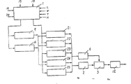
제1도는 본원 발명의 일실시예의 구성도1 is a block diagram of an embodiment of the present invention
제2도는 본원 발명의 다른 실시예의 구성도.2 is a block diagram of another embodiment of the present invention.
제3도는 제1도에 나타낸 실시예에 있어서의 컴퓨터프로그램의 구성예를 나타내는 도면.FIG. 3 is a diagram showing an example of the configuration of a computer program in the embodiment shown in FIG.
제4도는 차량의 상태와 운전자의 의지에 대한 각 제어방법의 관계를 나타내는 도면.4 is a diagram showing the relationship between each control method for the state of the vehicle and the driver's will.
* 도면의 주요부분에 대한 부호의 설명* Explanation of symbols for main parts of the drawings
1 : 상태판별부 2 : 엔진1: Status discriminating unit 2: Engine
3 : 연료분사 제어장치 4 : 점화시기 제어장치3: fuel injection control device 4: ignition timing control device
5 : 토크제어기구 9 : 속도제어기구5: torque control mechanism 9: speed control mechanism
12 : 기어 14 : 추적제어기구12: gear 14: tracking control mechanism
15 : 거리센서15: distance sensor
본원 발명은 내연기관 제어용의 연료분사장치와 점화장치에 관한 것이며, 특히 운전자의 운전에 관한 다양한 요구를 충족시키기에 적합한 상태적응형 내연기관 제어장치 및 제어방법에 관한 것이다.TECHNICAL FIELD The present invention relates to a fuel injection device and an ignition device for controlling an internal combustion engine, and more particularly, to a state adaptive internal combustion engine control device and a control method suitable for satisfying various demands regarding a driver's driving.
종래의 전자식 연료분사 제어장치는 흡입공기량에 따른 연료량을 간헐적으로 공급하는 방법을 취하고, 가속이나 감속시에는 연료량을 다시 증감하는 방법을 취하고 있었다(하기(1), (2) 참조). 이 방법은 정속주행시에는 부하 균형이 맞는 공기량과 연료량을 내연기관에 공급할 수 있으므로 불편은 없다. 그러나 가감속과 같은 과도상태에 있어서는 내연기관에 대한 적절한 제어를 하기 어려운 결점이 있었다.Conventional electronic fuel injection control devices have adopted a method of intermittently supplying a fuel amount corresponding to the intake air amount, and a method of increasing or decreasing the fuel amount again at the time of acceleration or deceleration (see (1) and (2) below). This method can supply the internal combustion engine with a balanced load of air and fuel at constant speed, so there is no inconvenience. However, under transient conditions such as acceleration and deceleration, it was difficult to properly control the internal combustion engine.
상기와 같은 종래의 제어장치는 운전성에 대한 고기능 또한 다양한 요구에 대하여, 충분한 기능을 제공할 수 없었다. 한편에서는 고기능적인 요구에 대해 토크서보제어나 속도서보제어(하기의 (3), (5))가 제안되어 있으나, 차량이 조우(遭遇)하는 모든 조건하에서의 적당한 제어를 행하는 종합제어라는 점에 대해서 충분한 배려가 되어 있지 않았다.The conventional control apparatus as described above could not provide sufficient functions for a variety of demands for high function and operability. On the other hand, torque servo control and speed servo control (3 and 5 below) have been proposed for high-performance requirements, but it is a comprehensive control that performs appropriate control under all conditions encountered by the vehicle. There was not enough consideration.
그리고 이런 종류의 장치에 관련되는 종래의 기술에는 예를들면 하기와 같은 것이 있다.And the conventional art related to this kind of apparatus is as follows, for example.
(1) 데이 : 엔진제어, 전기학회잡지 제10권, 12호, 1148페이지(소 56(1981)-12)…마이크로컴퓨터에 의한 제어 ; 랠은 테이블·룩·업 방식에 관한 것이다.(1) Day: Engine Control, Institute of Electrical Engineers Vol. 10, No. 12, p. 1148 (S 56 (1981) -12). Control by microcomputer; Rall is about the table lookup method.
(2) 나가야마 외 : 마이크로컴퓨터에 의한 엔진의 집중제어, 시스템과 제어, 24권, 5호, 306페이지(소55(1980-5) ; 이것은 엔진작동의 플로차트, 연료분사제어, 점화시기제어, 아이들링회전수제어에 관한 것이다.(2) Nagayama et al .: Centralized Control of Engines by Microcomputers, Systems and Controls, Vol. 24, No. 5, p. 306 (S 55 (1980-5); this is a flowchart of engine operation, fuel injection control, ignition timing control, It relates to idling speed control.
(3) 티. 다베 외 : 자동차의 엔진제어에 대한 진보적 제어이론에 대한 응용(On the Application of Modern Control Theory to Automotive Entgine Control, IECON '85) ; 이것은 토크서보에 관한 것이다.(3) t. Darbe et al .: On the Application of Modern Control Theory to Automotive Entgine Control (IECON '85); This is about torque servo.
(4) 일본국 특허공개 제1982-73836호 공보(4) Japanese Patent Publication No. 1982-73836
(5) 이모 : 엔진제어와 구동제어의 복합제어에 있어서의 최적화에 대하여, 자동차기술 소 61-(1986)-2 ; 이것은 속도서보에 관한 것이다.(5) Aunt: Automobile engineering subsection 61- (1986) -2 for optimization in the combined control of engine control and drive control; This is about speed servos.
상기의 종래 기술은 차량에 있어서의 내연기관의 제어를 시스템으로서 종합적으로 파악하려는 배려가 충분히 되어 있지 않았다. 이 때문에 차량이 이용되는 모든 상황에 대응하는 제어방법이 갖추어지지 않았거나, 또는 제어방법의 파라미터의 설정이 용이하지 않다는 문제가 있었다.The above prior art has not been given enough consideration to comprehensively grasp the control of the internal combustion engine in a vehicle as a system. For this reason, there has been a problem that a control method corresponding to all situations in which a vehicle is used is not provided, or setting of a parameter of the control method is not easy.
그 이유의 하나는, 차량이 조우하는 상태가 정속주행이나 아이들링 운전과 같은 정상상태와, 가감속과 같은 과도상태의 반복에도 불구하고, 종래의 제어방식이 정적인 모델로 구성되어 있다는 점에 기인하는 것이다. 또한 차량이용자의 요구는 과도상태에 있어서의 차량의 거동에 대하여 엄격해지고 있다. 이 때문에 과도상태를 관측하는 계측기를 설치하였다손 치더라도 정적(靜的)인 모델은 그것들을 충분히 활용할 수 없다.One of the reasons is that the conventional control method is composed of a static model despite the repetition of steady state such as constant speed driving and idling driving and transient state such as acceleration and deceleration. It is. In addition, the demands of vehicle users have become strict with respect to the behavior of the vehicle in the transient state. For this reason, static models cannot utilize them sufficiently even if they have installed instruments to monitor the transients.
정적인 제어모델에 관도상태의 보정을 가하는 종래의 방법으로는 차량의 특성이나, 계축기, 조작기 등이 다양하게 상이한 각 차종에 대하여 제어방법을 구체화하고 조정하는데는 많은 연구가 필요하게 된다.As a conventional method of applying the correction of the inertia state to the static control model, much research is required to specify and adjust the control method for each vehicle type having various characteristics of the vehicle, the machine, the manipulator, and the like.
상기의 문제점을 해결하기 위해서 본원 발명에서는, 차량의 상태와 운전자의 의사를 판별분류하고 분류마다 적당한 제어방법을 선택한다. 또한 운전자의 감성이나 기호에 차량의 움직이는 특성을 적합시키는데는 운전자의 기호를 예를 들면 경쾌, 쾌적, 경제적 등의 운전모드로 분류하고, 각 모드에 적합하도록 각 제어방법의 파라미터(계수치)를 변경하면 된다. 상기 판별분류에 상응되는 제어방법의 선택을 구체화하기 위해서는 내연기관 제어장치에 입력되는 컴퓨터의 소프트웨어의 구성을 상기 상태판별분류의 기능이 다른 기능보다 우선적으로 실시되도록 높은 우선레벨로 앨러케이트하면 된다.In order to solve the above problems, the present invention discriminates and classifies the state of the vehicle and the intention of the driver, and selects an appropriate control method for each classification. In addition, in order to fit the moving characteristics of the vehicle to the driver's emotions or preferences, the driver's preferences are classified into driving modes such as lightness, comfort, and economics, and the parameters (count values) of each control method are changed to suit each mode. Just do it. In order to specify the selection of the control method corresponding to the discrimination classification, the software configuration of the computer input to the internal combustion engine control apparatus may be allotted to a high priority level so that the function of the status discrimination classification is performed in preference to other functions.
차량의 상태와 운전자의 의사의 판별분류는 하기와 같이 행하여진다. 차량의 주행상태는 차속과 차속의 변화에 의해 검출된다. 운전자는 주행에 대한 의사표시를 토크전달기구(클러치 및 변속기)의 접속과, 브레이크페달 또는 액셀페달을 밟으므로써 행한다. 즉 양 페달의 밟기에 따라 차량의 상황에 따른 의사표시를 하고 있다. 페달의 각도, 각(角)속도 및 그것들의 시계열적인 궤적이 의사를 나타내고 있다.The classification of the state of the vehicle and the intention of the driver is performed as follows. The running state of the vehicle is detected by the vehicle speed and the change of the vehicle speed. The driver makes the intention to drive by connecting the torque transmission mechanisms (clutch and transmission) and stepping on the brake pedal or accelerator pedal. In other words, according to the pressing of the pedals, the intention is displayed according to the situation of the vehicle. Pedal angles, angular velocities and their time-series trajectories are indicative.
차속과 그 시간변화, 브레이크와 액셀의 양 페달의 각도와 각 속도의 각기 계측기의 과거로부터 현시점까지의 수치에 의해 차량의 상태와 운전자의 의사가 상세하게 검출된다. 또는 그것들을 사용함으로써 차량의 상태와 운전자의 의사를 추정하고 장래의 차량의 상태를 예측하는 것도 가능하다.The condition of the vehicle and the driver's intention are detected in detail by the vehicle speed, its time change, the angles of both pedals of the brake and the accelerator, and the numerical values from the past to the present on the respective measuring instruments of each speed. Or by using them, it is also possible to estimate the state of a vehicle, the driver's intention, and to predict the state of a future vehicle.
제어의 구성방법으로서는 실시예로 후술하는 바와 같이 토크서보, 속도서보, 추적서보를 캐스케이드구성에 의해 실현하는 방법과, 상기의 각종 제어방식을 병렬적으로 준비하는 방법이 있다.As a configuration method of control, there are a method of realizing a torque servo, a speed servo, a tracking servo by a cascade configuration and a method of preparing the various control methods in parallel as described later.
운전자의 차에 대한 기호를 구현화하는 방법으로서는 예를 들면 운전성에 중점을 두는 "경쾌", 승차기분에 중점을 두는 "쾌적", 실용성에 중점을 두는 "경제적"의 3가지의 선택스위치를 설치하고, 그 선택에 따라 각 제어방법의 파라미터를 변경하도록 한다.As a method of embodying the driver's preference, for example, three selection switches of "lightness" focusing on drivingability, "comfort" focusing on riding comfort, and "economical" focusing on practicality are installed. Then, the parameters of each control method can be changed according to the selection.
상기 방법을 구현화하는데 사용되는 컴퓨터는 종래보다도 고속의 것을 사용하고, 그 소프트웨어의 구성으로서는, 상태판별과 제어방법의 선택을 최우선으로 실시하도록 하는 구성을 채용하면 된다.The computer used to implement the above method is faster than the conventional one, and the configuration of the software may be such that the state discrimination and the selection of the control method are prioritized.
우선 본원 발명의 원리를 제4도에 의거 설명한다.First, the principle of this invention is demonstrated based on FIG.
제4도는 차량의 상태와 운전자의 의지의 판별분류와 각 분류에 해당하는 제어방법을 나타낸다.4 shows the classification of the state of the vehicle and the driver's will, and a control method corresponding to each classification.
차량의 상태는 정지하고 있는가 또는 움직이고 있는가로 대별된다. 운전자의 의사는 브레이크페달을 밟고 있는가, 브레이크 페달도 액셀페달도 밟고 있지 않은가, 액셀페달을 밟고 있는가, 멈추고 있는가, 또는 되돌리고 있는가의 5종류의 상태로 판별할 수 있다. 또한 정차중에는 토크전달기구를 접속하는가, 절단하는 가로 상태가 세분화된다.The state of the vehicle is roughly divided into whether it is stationary or moving. The driver's intention can determine whether the driver's brake pedal is stepped on, whether the brake pedal or the accelerator pedal is being stepped on, the accelerator pedal is being stepped on, stopped, or returned. During the stop, the transverse state of connecting or cutting the torque transmission mechanism is subdivided.
토크전달기구가 온(접속)으로 액셀페달을 밟았을때에는 가속요구에 대한 제어를 실시한다. 주행중에 액셀페달을 되돌리고 브레이크페달을 밟는 동안은 감속제어를 실시한다. 그때 아이들스위치가 온에서 회전수가 지나치게 높을 경우에는 퓨엘컷(fuel cut)제어를 행한다.When the accelerator pedal is stepped on when the torque transmission mechanism is on, the acceleration control is controlled. The accelerator pedal is returned while driving and the deceleration control is performed while the pedal is pressed. If the idle speed is too high when the idle switch is turned on, the fuel cut control is performed.
주행상태에 있으면서 가속도 감속도 아닌 경우에는 공연비를 소망치에 유지하는 공연비제어를 행한다.If the vehicle is in a running state and the acceleration is not decelerated, air-fuel ratio control is performed to keep the air-fuel ratio at a desired value.
토크전달기구가 오프일때는 아이들스피드제어에 의해 엔진회전수를 목표치에 유지하는 제어가 작용한다. 이때 액셀페달을 밟으면 공연상태이긴하나 상기의 공연비제어로 이행한다.When the torque transmission mechanism is off, a control is performed to maintain the engine speed at the target value by idling speed control. At this time, if the accelerator pedal is pressed, the performance is in a state of performance, but the above air-fuel ratio control is performed.
상기와 같은 차량의 상태와 운전자의 의사를 판별분류하여 제어방식을 선택하는 방법은 차량 이용자의 다양한 요구와 그것을 해결하는 새로운 기술의 도입에 단계적으로 대응하는데 적합하다. 그것은 설계개발자 및 제어방식의 매칭(파라미터 조정)을 하는 사람에게 있어서는 필요한 분류의 제어방식만을 이해하면 된다는 것과, 컴퓨터의 프로그램 수정도 일부의 모듈(module) 수정으로 족하다는 등의 이점을 의미한다.The method of selecting a control method by discriminating and classifying the state of the vehicle and the driver's intention as described above is suitable for responding step by step to the various demands of the vehicle user and the introduction of new technology to solve it. This means that design developers and those who match the control method (parameter adjustment) need to understand only the control method of the necessary classification, and that the modification of the program of the computer is sufficient for some module modification.
이하 본원 발명의 일실시예를 제1동 의거 설명한다. 제1도는 상태판별부와 그 결과를 받아 작동하는 캐스케이드의 제어계로 구성되어 있다.Hereinafter, an embodiment of the present invention will be described based on the first. 1 is composed of a status discriminating unit and a cascade control system which operates according to the result.
상태판별부(1)에서는 차량의 상태를 차속(V), 엔진회전수(N), 엔진출력토크(T) 및 차의 전방에 있는 장해물과 선행차와의 거리(L)등에 의해 검지하며, 한편 운전자의 의사를 브레이크페달각(θbr)를 나타내는 신호(20)와, 액셀페달각(θac)을 나타내는 신호(19)와 이들 여러가지량의 과거치와의 연산에 의해 얻어지는 시간적(동적)인 변화에 의하여 검지한다. 이들 검지결과와 운전자의 기호에 의거하여 필요한 제어방법은 무엇인가를 판별하고, 캐스케이드에 구성된 제어계의 구성결정을 파라미터의 선택이나 그 값의 변경을 행한다.The state
제어계는 엔진(2)의 회전수(N)와 토크(T)를 제어하기 위해 엔진에 가까운 안쪽으로부터 토크서보계, 속도서보계, 추적서보게가 캐스케이드에 구성되어 있다.In the control system, a cascade of a torque servometer, a speed servometer, and a tracking servo is configured from the inside close to the engine to control the rotation speed N and the torque T of the
엔진(2)에의 연료공급은 연료분사제어장치(3)에 의해 행하여지고, 점화시기는 점화시기 제어장치(4)에 의해 행하여진다.The fuel supply to the
토크제어기구(5)에서는 전후의 제어계로부터 요구되는 토크편차에 따른 연료량과 점화시기를 결정하여 그 결과를 연료분사장치(3)와 점화시기 제어장치(4)로 부여한다. 점화시기 제어장치(4)는 저속이나 정상주행시에는 토크제어기구(5)에 의해 결정되는 점화시기에 따라 작동하나, 과도상태에 있어서 상태판별부(1)가 신속한 서지(surge) 방지대책을 필요로 했을때에는 점화시기를 직접 제어하는 것도 가능하다.The
상태판별부(1)에서 토크서보가 선택되었을때에는 상태판별부(1)에 의해 그 목표치가 토크목표치 설정부(6)에 부여된다. 따라서 토크제어기구(5)의 입력은 토크목표치와 엔진토크의 실측치와의 매칭(matching)치가 된다. 토크서보의 선택스위치(7)는 상태판별부(1)에서의 판정결과에 따라 선택된다. 토크측정부(8)는 토크측 정량의 공학치변환과 평활화를 행한다. 전후의 속도서보가 선택되어 있는 경우에는 속도제어기구(9)의 출력이 토크제어기구(5)의 입력이 된다.When the torque servo is selected in the
가속, 감속의 반복이 많은 운전인 경우에는, 운전자는 액셀페달을 밟으므로써 토크의 증가를 요구하며, 발을 떼므로써 토크의 감소를 지시하고 있으므로, 상태판별부(1)에서는 액셀페달의 움직임에 따른 토크목표치를 부여한다. 또는 토크제어기구(5)에 대해서 토크편차를 직접 부여하는 것도 가능하다.In the case of a lot of repetition of acceleration and deceleration, the driver asks to increase the torque by stepping on the accelerator pedal, and instructs to decrease the torque by releasing the foot. Give the torque target value accordingly. Alternatively, it is also possible to directly give the torque deviation to the
정속주행(크루즈)제어나 아이들스피드제어(ISC)가 선택되었을때는, 상태판별부(1)에서 선택스위치(10)를 선택하고, 상태판별부(1)에서 속도목표치 설정부(11)에 부여한 목표속도와 실측차속을 매치시켜, 속도제어기구(9)로 차속이 목표치에 가까워지도록 제어한다. 실측차속은 차속측정부(13)에 있어서 엔진(2)으로부터 기어(12)를 통하여 얻어지는 차축회전수에 타이어지름 등의 보정을 가하여 계열적 데이터를 평활해서 얻는다.When the constant speed cruise control or idle speed control is selected, the selection switch 10 is selected in the
정속주행을 선택하고 있어도 운전자가 액셀페달을 밟았을때에는 스위치(7)가 들어가 토크서보계로 이행한다.Even when the cruise control is selected, when the driver presses the accelerator pedal, the
차량에 전방장해물과의 거리평정용센서가 설치되어 있는 경우에는, 정속주행 선택스위치(도시생략)로부터의 신호(17)가 선택되며, 또한 앞차와의 차간 거리가 허용치이내가 되면 속도서보로부터 추적서보로 이행한다.If the vehicle is equipped with a distance measuring sensor with a front obstacle, the
추적제어기구는 전방장해물로부터의 거리를 측정하는 거리센서(15)로부터의 측정치와, 차속에 따라 정해진 차간거리 목표치의 차에 따라서 속도의 증감량을 결정하여 속도제어기구(9)의 입력으로 한다. 차간거리 목표치는 상태판별부(1)에 의해 결정되어 차간거리 목표치 설정부(16)에 보내지고, 이 값은 거리차의 산출에 사용된다.The tracking control mechanism determines the increase / decrease amount of the speed according to the difference between the measured value from the
상태판별부(1)에 있어서의 판별결과와 캐스케이드제어부의 구성과의 대응은 제1표에 나타낸 바와 같이 된다.The correspondence between the discrimination result in the
[표 1]TABLE 1

범례Legend
○ : 기여도 큼, △ : 기여도 중간, - : 기여도 작음○: high contribution, △: medium contribution,-: low contribution
상태판별결과, 가속이나 감속제어가 필요하다고 판정되면 토크제어가 주체적으로 기능한다. 이때 정속주행이 선택되어 있으면 속도제어도 기능하고, 거리센서가 작동중이면 추적제어도 기능한다. 퓨엘컷제어는 토크제어의 범위내에서 실행된다. 공연비제어는 토크제어중에 있어서 연료비의 향상과 배기개스의 경감을 도모하도록 실행된다. 정속주행이나 추적주행 때에도 공연비제어는 유효하게 기능한다. 아이들스피드제어는 아이들 회전수를 목표치로 한 속도제어가 기능한다.As a result of the status determination, if it is determined that the acceleration or deceleration control is necessary, the torque control mainly functions. At this time, if constant speed driving is selected, speed control is functioning, and if distance sensor is working, tracking control is also functioning. The fuel cut control is executed within the range of torque control. The air-fuel ratio control is executed to improve the fuel cost and reduce the exhaust gas during torque control. The air-fuel ratio control is effective even when driving at constant speed or tracking. Idle speed control functions as a speed control aimed at idle rotation speed.
상태판별부(1)의 입력인 운전모드선택(18)의 결과를 제2표에 나타낸다.The result of the
[표 2]TABLE 2

범례Legend
○ : 기여도 큼, △ : 기여도 중간, - : 기여도 작음○: high contribution, △: medium contribution,-: low contribution
제2표에 의하면 "경쾌", "쾌적", "경제적"의 각 모드는 주로 토크제어의 제어파라미터의 변경에 따라 대응한다. "쾌적"에 대해서는 정속주행제어기능이나 거리센서의 구비와 어울려서 속도제어나 추적제어가 유효하게 기능한다. "경제적"은 속도제어도 병용가능하지만, 정속제어의 정도를 약간 늦추어도 연료비를 절약할 수 있는 제어연산방식을 채용한다.According to the second table, the respective modes of "light", "comfortable" and "economic" correspond mainly to changes in control parameters of torque control. In terms of "comfort", speed control and tracking control function effectively in combination with the constant speed drive control function and the provision of a distance sensor. Although "economical" speed control can be used in combination, a control calculation method is adopted that can save fuel costs even if the degree of constant speed control is slightly slowed down.
제1도와 같은 목적을 갖는 다른 구성예를 제2도에 나타낸다. 제2도는 상태판별부(1)에서의 판별결과에 의거하여, 제어방법의 대체안중에서 적당한 제어방식을 선택해서 사용하는 구성을 나타내고 있다. 제어방식의 대체안으로서는 가속제어(21), 감속제어(22), 퓨엘컷제어(23), 공연비제어(24), 아이들스피드제어(25)가 기본이다. 이들 5종류의 제어는 어느것이 연산결과로서, 연료량과 점화타이밍을 각기 연료분사제어장치(3)와 점화시기제어장치(4)에 부여한다.Another structural example with the same objective as FIG. 1 is shown in FIG. 2 shows a configuration in which an appropriate control method is selected and used among alternatives of the control method based on the result of the discrimination in the
가속제어, 감속제어, 퓨엘컷제어가 선택된 경우에는, 이들 제어를 급격하게 가하면 차량의 상태에 따라서는 서지현상이 야기될 염려가 있기 때문에, 차량의 상태와 선택된 제어방식을 의거 예측계산을 하며, 서지현상의 발생이 예견될때는, 공연비제어를 선택하기로 하고, 이미 선택된 제어방법의 파라미터치를 변경하기도 한다.When acceleration control, deceleration control, and fuel cut control are selected, suddenly applying these controls may cause surge depending on the state of the vehicle. Therefore, prediction calculation is performed based on the state of the vehicle and the selected control method. When the occurrence of a surge phenomenon is foreseen, the air-fuel ratio control is selected, and the parameter value of the already selected control method is changed.
제1도에 나타낸 엔진에 대한 종합적인 제어를 구체화하는데는 컴퓨터가 불가결하다. 컴퓨터의 프로그램 구성은 제3도와 같이 된다.A computer is indispensable to embody the comprehensive control for the engine shown in FIG. The program configuration of the computer is as shown in FIG.
제3도에 나타내는 프로그램은 인터럽트(interrupt)처리(31)에 의해 가동되며, 인터럽트판정(32)에 의해 주기적인 인터럽트처리(33)이나, 그것에 의해 가동되는 AD변환개시(34)후에 발생하는 AD 변환종료 인터럽트처리(35)에 의해 분기가 일어난다. AD 변환종료에 있어서는 제1도에 기술한 상태판별을 행하여 제어방법의 선택을 한다. 그 선택결과에 의거하여 타스크분배(36)에서는 이하의 타스크의 어느것인가를 부른다. 타스크레벨(0)에서는 점화시기제어(4), 연료분사제어(3), 토크제어(5)가 할당되어서 신속한 대응을 한다. 타스크레벨(1)에서는 속도제어(9), 추적제어(14) 등이 할당된다. 이것들보다도 더욱 완만하게 대응해도되는 프로그램은 타스크레벨(2) 이후에 앨리케이트된다.The program shown in FIG. 3 is started by an interrupt
본 프로그램 구성상의 특징은 차량의 상태나 운전자의 의사를 AD 변환해서 입력한 시점에서, 상태판별처리를 실시하여 과도상태에 신속하게 대응할 수 있다는 점이다.The feature of this program configuration is that it is possible to respond quickly to the transient state by performing the state discrimination process at the time of AD conversion of the state of the vehicle or the driver's intention.
본원 발명에 의하면 차량의 상태와 운전자의 의사를 시시각각 신속하게 검출할 수 있으며, 더구나 그 결과에 따라 취해야 할 제어방법을 정확하게 결정할 수 있으므로 운전성의 향상, 엔진성능의 유효활용, 차종마다 다른 엔진성능에 매치되는 제어방법을 정확하게 결정할 수 있으므로 운전성의 향상, 엔진성능의 유효활용, 차종마다 다른 엔진성능에 매치되는 제어방식의 신속한 개발, 제어방식의 개발과 소프트웨어의 생산성을 향상시킬 수 있다.According to the present invention, it is possible to quickly detect the state of the vehicle and the driver's intention quickly, and furthermore, it is possible to accurately determine the control method to be taken according to the result, thereby improving driving performance, effectively utilizing engine performance, and different engine performance for each vehicle type. It is possible to accurately determine the control method to be matched to improve the driving performance, effective use of engine performance, rapid development of control methods that match the engine performance of each vehicle type, development of control methods and software productivity.
Claims (17)
Applications Claiming Priority (3)
| Application Number | Priority Date | Filing Date | Title |
|---|---|---|---|
| JP104650 | 1984-07-12 | ||
| JP86-104650 | 1986-05-09 | ||
| JP61104650A JP2564275B2 (en) | 1986-05-09 | 1986-05-09 | State adaptive internal combustion engine control system |
Publications (2)
| Publication Number | Publication Date |
|---|---|
| KR870011358A KR870011358A (en) | 1987-12-22 |
| KR950004606B1 true KR950004606B1 (en) | 1995-05-03 |
Family
ID=14386332
Family Applications (1)
| Application Number | Title | Priority Date | Filing Date |
|---|---|---|---|
| KR1019870004321A KR950004606B1 (en) | 1986-05-09 | 1987-05-02 | Condition adaptive-type control method for internal combustion engine |
Country Status (5)
| Country | Link |
|---|---|
| US (2) | US4853720A (en) |
| JP (1) | JP2564275B2 (en) |
| KR (1) | KR950004606B1 (en) |
| DE (1) | DE3715423A1 (en) |
| GB (1) | GB2191023B (en) |
Cited By (1)
| Publication number | Priority date | Publication date | Assignee | Title |
|---|---|---|---|---|
| KR20170065581A (en) * | 2014-11-05 | 2017-06-13 | 고쿠리츠켄큐카이하츠호진 카가쿠기쥬츠신코키코 | Semiconductor device which uses germanium layer as channel region and method for manufacturing same |
Families Citing this family (66)
| Publication number | Priority date | Publication date | Assignee | Title |
|---|---|---|---|---|
| US5189621A (en) * | 1987-05-06 | 1993-02-23 | Hitachi, Ltd. | Electronic engine control apparatus |
| KR940000039B1 (en) * | 1987-08-19 | 1994-01-05 | 가부시기가이샤 히다찌세이사꾸쇼 | Electronic engine control apparatus |
| DE3815625A1 (en) * | 1988-05-07 | 1989-11-16 | Koelner Verkehrs Betriebe Ag | METHOD FOR AUTOMATICALLY PRESENTING DRIVE PARAMETERS IN THE DRIVETRAIN OF A LINE BUS WITH AN AUTOMATIC TRANSMISSION, AND DEVICE FOR IMPLEMENTING THE METHOD |
| DE3937302A1 (en) * | 1989-11-09 | 1991-05-16 | Man Nutzfahrzeuge Ag | METHOD FOR SWITCHING AN UNSYNCHRONIZED (CLAW) MANUAL GEARBOX AND, IF NECESSARY, AUTOMATICALLY ACTUATING THE RELATED CLUTCH |
| JP2940042B2 (en) * | 1990-01-23 | 1999-08-25 | 日産自動車株式会社 | Vehicle control strategy device |
| JP2974440B2 (en) * | 1991-03-22 | 1999-11-10 | 株式会社日立製作所 | Automotive integrated control device |
| US5235512A (en) * | 1991-06-24 | 1993-08-10 | Ford Motor Company | Self-tuning speed control for a vehicle |
| DE4141947C2 (en) * | 1991-12-19 | 2002-02-07 | Bosch Gmbh Robert | Control system for a propulsion unit in an aircraft |
| DE4240117C2 (en) * | 1992-11-28 | 2003-09-25 | Bosch Gmbh Robert | Method and device for speed limitation of vehicles |
| US5483448A (en) * | 1992-12-14 | 1996-01-09 | Ford Motor Company | Adaptive vehicle suspension system with mechanism for varying controller gains in response to changing road roughness conditions |
| US5341703A (en) * | 1993-03-04 | 1994-08-30 | Ford Motor Company | Performance mode and economy mode shift scheduling in an automatic transmission |
| JP3079881B2 (en) * | 1993-08-10 | 2000-08-21 | 三菱自動車工業株式会社 | Road traffic condition estimation method and vehicle driving characteristic control method |
| DE4401416C2 (en) * | 1994-01-19 | 1998-04-16 | Daimler Benz Ag | Gradual driving style classification method and motor vehicle using the same |
| US5479898A (en) * | 1994-07-05 | 1996-01-02 | Ford Motor Company | Method and apparatus for controlling engine torque |
| US5839534A (en) * | 1995-03-01 | 1998-11-24 | Eaton Vorad Technologies, Llc | System and method for intelligent cruise control using standard engine control modes |
| AR001032A1 (en) * | 1995-03-01 | 1997-08-27 | Eaton Vorad Technologies Llc | ARRANGEMENT AND METHOD FOR INTEGRATING THE INTELLIGENT CRUISE CONTROL WITH AN ELECTRONICALLY CONTROLLED ENGINE |
| GB9601479D0 (en) * | 1996-01-25 | 1996-03-27 | Rover Group | A powertrain control system |
| US8140358B1 (en) | 1996-01-29 | 2012-03-20 | Progressive Casualty Insurance Company | Vehicle monitoring system |
| US8090598B2 (en) | 1996-01-29 | 2012-01-03 | Progressive Casualty Insurance Company | Monitoring system for determining and communicating a cost of insurance |
| US5797134A (en) * | 1996-01-29 | 1998-08-18 | Progressive Casualty Insurance Company | Motor vehicle monitoring system for determining a cost of insurance |
| US6868386B1 (en) | 1996-01-29 | 2005-03-15 | Progressive Casualty Insurance Company | Monitoring system for determining and communicating a cost of insurance |
| DE19637210B4 (en) | 1996-09-12 | 2007-05-24 | Siemens Ag | Powertrain control for a motor vehicle |
| DE69839616D1 (en) * | 1997-04-25 | 2008-07-24 | Hitachi Ltd | Method for setting a target drive torque and corresponding vehicle control |
| JP3578597B2 (en) * | 1997-06-30 | 2004-10-20 | 株式会社日立ユニシアオートモティブ | Control device for direct injection spark ignition type internal combustion engine |
| DE19730906A1 (en) * | 1997-07-18 | 1999-01-28 | Daimler Benz Ag | Method for setting the throttle valve and / or injection quantity of an internal combustion engine of a motor vehicle to the specification of the vehicle driver |
| US5978729A (en) * | 1997-10-15 | 1999-11-02 | Caterpillar Inc. | Electronic engine control and method of operating same |
| DE19807126C2 (en) * | 1998-02-20 | 2000-11-16 | Daimler Chrysler Ag | Method for adjusting the drive power of a motor vehicle |
| US6134499A (en) * | 1998-05-29 | 2000-10-17 | Cummins Engine Company, Inc. | System for controlling road speed of a vehicle driven by an internal combustion engine |
| FR2789732B1 (en) | 1999-02-12 | 2001-03-23 | Renault | METHOD AND DEVICE FOR CONTROLLING THE DRIVE UNIT OF A MOTOR VEHICLE |
| DE19906416A1 (en) | 1999-02-16 | 2000-08-17 | Bayerische Motoren Werke Ag | Torque adaptation device for engine torque model |
| DE19908907A1 (en) * | 1999-03-02 | 2000-09-28 | Daimler Chrysler Ag | Method and device for automatically influencing the driving behavior of a motor vehicle with an internal combustion engine |
| SE519190C2 (en) * | 2000-01-13 | 2003-01-28 | Saab Ab | Systems, craft and method regarding the behavior of vehicles |
| DE10008665A1 (en) * | 2000-02-24 | 2001-08-30 | Zahnradfabrik Friedrichshafen | Method of controlling motor vehicle drive system especially automatic transmission, involves using look-ahead variables for taking action on the vehicle systems |
| US6371081B1 (en) * | 2000-09-29 | 2002-04-16 | Detroit Diesel Corporation | Inhibit engine speed governor |
| EP1256479A1 (en) * | 2001-05-07 | 2002-11-13 | Ford Global Technologies, Inc., A subsidiary of Ford Motor Company | Method for driving style detection |
| DE10158480C1 (en) * | 2001-11-28 | 2003-10-09 | Omg Ag & Co Kg | Method and device for operating an engine of a motor vehicle |
| JP2003237409A (en) * | 2002-02-18 | 2003-08-27 | Hitachi Ltd | Vehicular automatic travel control method, system and acc controller |
| DE10310720A1 (en) * | 2003-03-10 | 2004-09-23 | Robert Bosch Gmbh | Method and device for regulating the speed of a motor vehicle |
| US20040214788A1 (en) * | 2003-03-11 | 2004-10-28 | Raj Madhwa H.G. | Treatment of prostate cancer |
| US7292152B2 (en) * | 2003-06-12 | 2007-11-06 | Temic Automotive Of North America, Inc. | Method and apparatus for classifying vehicle operator activity state |
| WO2005003885A2 (en) | 2003-07-07 | 2005-01-13 | Sensomatix Ltd. | Traffic information system |
| DE10348249A1 (en) * | 2003-10-16 | 2005-05-12 | Bosch Gmbh Robert | Detection device for detecting the desire of a driver of a motor vehicle after a certain total thrust torque of the vehicle |
| FR2872304A1 (en) * | 2004-06-28 | 2005-12-30 | Peugeot Citroen Automobiles Sa | Vehicle speed stabilizing method, involves monitoring possible willingness of driver to maintain vehicle around target speed based on monitored instantaneous speed and activating state of control units |
| FR2880591B1 (en) * | 2005-01-11 | 2008-08-22 | Renault Sas | LONGITUDINAL CONTROL SYSTEM OF A CAR |
| JP4462148B2 (en) * | 2005-09-01 | 2010-05-12 | 株式会社デンソー | Cruise control equipment |
| JP3872504B1 (en) | 2006-04-07 | 2007-01-24 | 富士重工業株式会社 | Vehicle engine control device |
| DE102007016617B4 (en) | 2006-04-07 | 2022-07-14 | Subaru Corporation | Driving force control unit for a vehicle |
| US8352146B2 (en) * | 2006-11-13 | 2013-01-08 | Ford Global Technologies, Llc | Engine response adjustment based on traffic conditions |
| EP2097296B1 (en) * | 2006-11-30 | 2017-04-05 | Bayerische Motoren Werke Aktiengesellschaft | Method for a motor vehicle with a pre-emptive temporary load reduction of the vehicle electric system |
| US7762924B2 (en) * | 2007-11-01 | 2010-07-27 | Ford Global Technologies, Llc | Transmission shifting responsive to borderline knock limits |
| US8214122B2 (en) * | 2008-04-10 | 2012-07-03 | GM Global Technology Operations LLC | Energy economy mode using preview information |
| DE112009002535T5 (en) * | 2008-10-30 | 2012-06-14 | Ford Global Technologies, Llc | Vehicle and method for advising a driver of the same |
| US9916625B2 (en) | 2012-02-02 | 2018-03-13 | Progressive Casualty Insurance Company | Mobile insurance platform system |
| US8738228B2 (en) * | 2009-10-30 | 2014-05-27 | Ford Global Technologies, Llc | Vehicle and method of tuning performance of same |
| US8886365B2 (en) * | 2009-10-30 | 2014-11-11 | Ford Global Technologies, Llc | Vehicle and method for advising driver of same |
| US8489433B2 (en) | 2010-07-29 | 2013-07-16 | Insurance Services Office, Inc. | System and method for estimating loss propensity of an insured vehicle and providing driving information |
| US8935080B2 (en) | 2012-01-26 | 2015-01-13 | Ford Global Technologies, Llc | Engine response adjustment |
| US8635018B2 (en) | 2012-02-03 | 2014-01-21 | International Business Machines Corporation | Managing a driver profile |
| US9719429B2 (en) | 2012-05-02 | 2017-08-01 | Cummins Ip, Inc. | Driver-assisted fuel reduction strategy and associated apparatus, system, and method |
| SE539122C2 (en) * | 2012-07-05 | 2017-04-11 | Scania Cv Ab | Procedure and systems for driving vehicles |
| JP5835293B2 (en) * | 2013-09-12 | 2015-12-24 | トヨタ自動車株式会社 | Internal combustion engine |
| GB2523195B (en) * | 2014-02-18 | 2017-10-25 | Jaguar Land Rover Ltd | Control system and method |
| JP2017115590A (en) * | 2015-12-21 | 2017-06-29 | 株式会社デンソー | Electronic control device |
| US10124802B2 (en) * | 2016-08-20 | 2018-11-13 | Toyota Motor Engineering & Manufacturing North America, Inc. | Controlled vehicle deceleration based on a selected vehicle driving mode |
| US10597034B2 (en) * | 2017-09-07 | 2020-03-24 | Ford Global Technologies, Llc | Method for adjusting requested vehicle torque |
| CN114670659B (en) * | 2021-03-23 | 2024-02-20 | 北京新能源汽车股份有限公司 | Vehicle torque control method and device and electric automobile |
Family Cites Families (8)
| Publication number | Priority date | Publication date | Assignee | Title |
|---|---|---|---|---|
| JPS5773836A (en) * | 1980-10-27 | 1982-05-08 | Toyota Motor Corp | Control method for internal combustion engine |
| JPS5974341A (en) * | 1982-10-19 | 1984-04-26 | Nissan Motor Co Ltd | Accelerator controlling apparatus for car |
| US4551802A (en) * | 1982-11-17 | 1985-11-05 | Eaton Corporation | Automatic transmission control method |
| US4597049A (en) * | 1982-12-28 | 1986-06-24 | Nissan Motor Company, Limited | Accelerator control system for automotive vehicle |
| DE3444544A1 (en) * | 1983-12-06 | 1985-06-20 | Nissan Motor Co., Ltd., Yokohama, Kanagawa | DRIVE CONTROL METHOD WITH SELECTABLE OPERATING MODES |
| JPS60121127A (en) * | 1983-12-06 | 1985-06-28 | Nissan Motor Co Ltd | Method of controlling power train |
| JPS60163733A (en) * | 1984-02-03 | 1985-08-26 | Nissan Motor Co Ltd | Device for controlling distance between cars |
| US4829434A (en) | 1987-04-29 | 1989-05-09 | General Motors Corporation | Adaptive vehicle |
-
1986
- 1986-05-09 JP JP61104650A patent/JP2564275B2/en not_active Expired - Fee Related
-
1987
- 1987-05-02 KR KR1019870004321A patent/KR950004606B1/en not_active IP Right Cessation
- 1987-05-06 US US07/046,388 patent/US4853720A/en not_active Ceased
- 1987-05-07 GB GB8710842A patent/GB2191023B/en not_active Expired - Lifetime
- 1987-05-08 DE DE19873715423 patent/DE3715423A1/en active Granted
-
1990
- 1990-02-21 US US07/482,508 patent/USRE37434E1/en not_active Expired - Lifetime
Cited By (2)
| Publication number | Priority date | Publication date | Assignee | Title |
|---|---|---|---|---|
| KR20170065581A (en) * | 2014-11-05 | 2017-06-13 | 고쿠리츠켄큐카이하츠호진 카가쿠기쥬츠신코키코 | Semiconductor device which uses germanium layer as channel region and method for manufacturing same |
| US10109710B2 (en) | 2014-11-05 | 2018-10-23 | Japan Science And Technology Agency | Semiconductor device having germanium layer as channel region and method for manufacturing the same |
Also Published As
| Publication number | Publication date |
|---|---|
| GB2191023B (en) | 1991-01-16 |
| KR870011358A (en) | 1987-12-22 |
| US4853720A (en) | 1989-08-01 |
| USRE37434E1 (en) | 2001-11-06 |
| GB2191023A (en) | 1987-12-02 |
| DE3715423C2 (en) | 1992-12-17 |
| GB8710842D0 (en) | 1987-06-10 |
| JPS62261622A (en) | 1987-11-13 |
| DE3715423A1 (en) | 1987-11-12 |
| JP2564275B2 (en) | 1996-12-18 |
Similar Documents
| Publication | Publication Date | Title |
|---|---|---|
| KR950004606B1 (en) | Condition adaptive-type control method for internal combustion engine | |
| US6125314A (en) | Drive train controller for a motor vehicle | |
| US4766544A (en) | Apparatus for automatically controlling starting of vehicle powered by internal combustion engine | |
| JP3977701B2 (en) | Accelerator control device | |
| USRE38241E1 (en) | Continuously variable transmission control method and apparatus | |
| JPH0585228A (en) | Electronic system of vehcle | |
| US7206690B2 (en) | Vehicle control apparatus | |
| JPS63251805A (en) | State-based adaptive control system for engine | |
| US20050075826A1 (en) | Acceleration control device | |
| CN101120166B (en) | Vehicle integrated-control apparatus and vehicle integrated-control method | |
| CN108216212A (en) | Control the system and method for turn inside diameter | |
| USRE37598E1 (en) | Continuously variable transmission control apparatus | |
| US20230415738A1 (en) | Braking/driving force control system | |
| JP3639419B2 (en) | Vehicle control method and vehicle control system | |
| JPH0942444A (en) | Driving force control device for vehicle | |
| US6314359B1 (en) | System for modifying a load bias function based on transient engine operation | |
| JPH0223369B2 (en) | ||
| US5609217A (en) | Constant-speed cruise control apparatus for a vehicle | |
| US6459981B1 (en) | Process and system for the automated influencing of the vehicle handling of a motor vehicle having an internal combustion engine | |
| JP2683648B2 (en) | Engine control device | |
| US5724942A (en) | Method and apparatus for regulating engine torque | |
| JPH07233755A (en) | Accelerator control device | |
| JP2575654B2 (en) | Engine control device | |
| US7684920B2 (en) | Method for driver input gauging | |
| JPS63154837A (en) | Throttle valve controller |
Legal Events
| Date | Code | Title | Description |
|---|---|---|---|
| A201 | Request for examination | ||
| G160 | Decision to publish patent application | ||
| E701 | Decision to grant or registration of patent right | ||
| GRNT | Written decision to grant | ||
| FPAY | Annual fee payment |
Payment date: 20040429 Year of fee payment: 10 |
|
| LAPS | Lapse due to unpaid annual fee |