KR930011034B1 - Method and apparatus for performing ophthalmic laser surgery - Google Patents
Method and apparatus for performing ophthalmic laser surgery Download PDFInfo
- Publication number
- KR930011034B1 KR930011034B1 KR1019870008309A KR870008309A KR930011034B1 KR 930011034 B1 KR930011034 B1 KR 930011034B1 KR 1019870008309 A KR1019870008309 A KR 1019870008309A KR 870008309 A KR870008309 A KR 870008309A KR 930011034 B1 KR930011034 B1 KR 930011034B1
- Authority
- KR
- South Korea
- Prior art keywords
- cornea
- area
- cross
- laser
- sectional area
- Prior art date
Links
Images


Classifications
-
- A—HUMAN NECESSITIES
- A61—MEDICAL OR VETERINARY SCIENCE; HYGIENE
- A61B—DIAGNOSIS; SURGERY; IDENTIFICATION
- A61B8/00—Diagnosis using ultrasonic, sonic or infrasonic waves
- A61B8/10—Eye inspection
-
- A—HUMAN NECESSITIES
- A61—MEDICAL OR VETERINARY SCIENCE; HYGIENE
- A61F—FILTERS IMPLANTABLE INTO BLOOD VESSELS; PROSTHESES; DEVICES PROVIDING PATENCY TO, OR PREVENTING COLLAPSING OF, TUBULAR STRUCTURES OF THE BODY, e.g. STENTS; ORTHOPAEDIC, NURSING OR CONTRACEPTIVE DEVICES; FOMENTATION; TREATMENT OR PROTECTION OF EYES OR EARS; BANDAGES, DRESSINGS OR ABSORBENT PADS; FIRST-AID KITS
- A61F9/00—Methods or devices for treatment of the eyes; Devices for putting-in contact lenses; Devices to correct squinting; Apparatus to guide the blind; Protective devices for the eyes, carried on the body or in the hand
- A61F9/007—Methods or devices for eye surgery
- A61F9/008—Methods or devices for eye surgery using laser
- A61F9/00802—Methods or devices for eye surgery using laser for photoablation
- A61F9/00804—Refractive treatments
-
- A—HUMAN NECESSITIES
- A61—MEDICAL OR VETERINARY SCIENCE; HYGIENE
- A61F—FILTERS IMPLANTABLE INTO BLOOD VESSELS; PROSTHESES; DEVICES PROVIDING PATENCY TO, OR PREVENTING COLLAPSING OF, TUBULAR STRUCTURES OF THE BODY, e.g. STENTS; ORTHOPAEDIC, NURSING OR CONTRACEPTIVE DEVICES; FOMENTATION; TREATMENT OR PROTECTION OF EYES OR EARS; BANDAGES, DRESSINGS OR ABSORBENT PADS; FIRST-AID KITS
- A61F9/00—Methods or devices for treatment of the eyes; Devices for putting-in contact lenses; Devices to correct squinting; Apparatus to guide the blind; Protective devices for the eyes, carried on the body or in the hand
- A61F9/007—Methods or devices for eye surgery
- A61F9/008—Methods or devices for eye surgery using laser
- A61F9/009—Auxiliary devices making contact with the eyeball and coupling in laser light, e.g. goniolenses
-
- B—PERFORMING OPERATIONS; TRANSPORTING
- B23—MACHINE TOOLS; METAL-WORKING NOT OTHERWISE PROVIDED FOR
- B23K—SOLDERING OR UNSOLDERING; WELDING; CLADDING OR PLATING BY SOLDERING OR WELDING; CUTTING BY APPLYING HEAT LOCALLY, e.g. FLAME CUTTING; WORKING BY LASER BEAM
- B23K26/00—Working by laser beam, e.g. welding, cutting or boring
- B23K26/08—Devices involving relative movement between laser beam and workpiece
- B23K26/082—Scanning systems, i.e. devices involving movement of the laser beam relative to the laser head
-
- A—HUMAN NECESSITIES
- A61—MEDICAL OR VETERINARY SCIENCE; HYGIENE
- A61B—DIAGNOSIS; SURGERY; IDENTIFICATION
- A61B17/00—Surgical instruments, devices or methods, e.g. tourniquets
- A61B17/30—Surgical pincettes without pivotal connections
- A61B2017/306—Surgical pincettes without pivotal connections holding by means of suction
-
- A—HUMAN NECESSITIES
- A61—MEDICAL OR VETERINARY SCIENCE; HYGIENE
- A61B—DIAGNOSIS; SURGERY; IDENTIFICATION
- A61B18/00—Surgical instruments, devices or methods for transferring non-mechanical forms of energy to or from the body
- A61B18/18—Surgical instruments, devices or methods for transferring non-mechanical forms of energy to or from the body by applying electromagnetic radiation, e.g. microwaves
- A61B18/20—Surgical instruments, devices or methods for transferring non-mechanical forms of energy to or from the body by applying electromagnetic radiation, e.g. microwaves using laser
- A61B2018/2035—Beam shaping or redirecting; Optical components therefor
- A61B2018/20351—Scanning mechanisms
- A61B2018/20355—Special scanning path or conditions, e.g. spiral, raster or providing spot overlap
-
- A—HUMAN NECESSITIES
- A61—MEDICAL OR VETERINARY SCIENCE; HYGIENE
- A61F—FILTERS IMPLANTABLE INTO BLOOD VESSELS; PROSTHESES; DEVICES PROVIDING PATENCY TO, OR PREVENTING COLLAPSING OF, TUBULAR STRUCTURES OF THE BODY, e.g. STENTS; ORTHOPAEDIC, NURSING OR CONTRACEPTIVE DEVICES; FOMENTATION; TREATMENT OR PROTECTION OF EYES OR EARS; BANDAGES, DRESSINGS OR ABSORBENT PADS; FIRST-AID KITS
- A61F9/00—Methods or devices for treatment of the eyes; Devices for putting-in contact lenses; Devices to correct squinting; Apparatus to guide the blind; Protective devices for the eyes, carried on the body or in the hand
- A61F9/007—Methods or devices for eye surgery
- A61F9/008—Methods or devices for eye surgery using laser
- A61F2009/00861—Methods or devices for eye surgery using laser adapted for treatment at a particular location
- A61F2009/00872—Cornea
-
- A—HUMAN NECESSITIES
- A61—MEDICAL OR VETERINARY SCIENCE; HYGIENE
- A61F—FILTERS IMPLANTABLE INTO BLOOD VESSELS; PROSTHESES; DEVICES PROVIDING PATENCY TO, OR PREVENTING COLLAPSING OF, TUBULAR STRUCTURES OF THE BODY, e.g. STENTS; ORTHOPAEDIC, NURSING OR CONTRACEPTIVE DEVICES; FOMENTATION; TREATMENT OR PROTECTION OF EYES OR EARS; BANDAGES, DRESSINGS OR ABSORBENT PADS; FIRST-AID KITS
- A61F9/00—Methods or devices for treatment of the eyes; Devices for putting-in contact lenses; Devices to correct squinting; Apparatus to guide the blind; Protective devices for the eyes, carried on the body or in the hand
- A61F9/007—Methods or devices for eye surgery
- A61F9/008—Methods or devices for eye surgery using laser
- A61F9/00802—Methods or devices for eye surgery using laser for photoablation
- A61F9/00817—Beam shaping with masks
- A61F9/00819—Beam shaping with masks with photoablatable masks
Abstract
내용 없음.No content.
Description
제1도는 본 발명의 작동부품들의 일반적인 배열상태를 나타내는 개략적인 사시도.1 is a schematic perspective view showing a general arrangement of operating parts of the present invention.
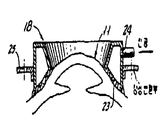
제2도는 제1도에 도시한 장치에 사용하는 눈 유지 고정구의 개략적인 종단면도.FIG. 2 is a schematic longitudinal sectional view of an eye retention fixture for use with the device shown in FIG.
제3도, 4도 및 5도는 근시를 교정하는 경우에 있어서 제1도에 도시한 장치로 수행할 수 있는 융제(ablation)식 각막 절삭 특성을 나타내는 개략도.3, 4, and 5 are schematic diagrams showing ablation corneal cutting characteristics that can be performed with the apparatus shown in FIG. 1 when correcting myopia.
제6도는 본 발명의 다른 실시예의 작동 부품들을 도시한 개략도.6 is a schematic diagram showing operating parts of another embodiment of the present invention.
제7도는 제6도의 실시예에서 사용할 수 있는 인덱스가능한 마스크(indexible mask)의 평면도.7 is a plan view of an indexable mask that can be used in the embodiment of FIG.
제8도는 제6도에 도시한 장치의 변형된 실시예를 나타내는 개략도.FIG. 8 is a schematic diagram showing a modified embodiment of the device shown in FIG.
제9도는 제8도의 변형예에서 사용할 수 있는 인덱스가능한 마스크의 부품 평면도.9 is a plan view of a part of an indexable mask usable in the variant of FIG.
제10도 및 11도는 원시상태를 교정하는데 있어서 본 발명을 사용하는 상태를 나타내는 개략도.10 and 11 are schematic diagrams illustrating a state of using the present invention in correcting a primordial state.
제12도, 13도 및 14도는 각막 전방 외부면에 프레넬(Fresnel)형의 시각교정 형태를 얻기 위해 본 발명을 사용하는 상태를 나타낸 단순 개략도.12, 13 and 14 are simplified schematic diagrams showing the state of using the present invention to obtain a Fresnel type visual correction form on the anterior corneal front surface.
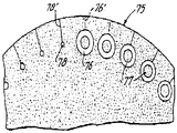
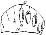
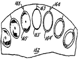
제15도 및 16도는 난시를 교정하기 위한 본 발명의 실시예의 부품 및 특징을 각각 나타내는 도면.15 and 16 illustrate the components and features of an embodiment of the present invention for correcting astigmatism, respectively.
제17도 및 18도는 각막 이식 수술과 관련하여 본 발명을 사용하는 상태를 나타낸 단순 개략도.17 and 18 are simplified schematic diagrams illustrating the use of the present invention in connection with corneal transplant surgery.
제19도 및 20도는 제15도 및 16도에 도시한 실시예의 두 개의 다른 변형예를 도시한 단순 개략도.19 and 20 are simple schematic diagrams showing two different variations of the embodiment shown in FIGS. 15 and 16.
제21도 내지 26도는 본 발명의 또 다른 특징을 나타내는, 제6도, 7도, 8도, 9도, 11도 및 14도에 각각 대응된 도면.21 to 26 are views corresponding to FIGS. 6, 7, 8, 9, 11 and 14, respectively, showing yet another feature of the present invention.
제27도 및 28도는 반사기 구조의 원리를 나타내는 그래프.27 and 28 are graphs showing the principle of the reflector structure.
제29도 및 30도는 본 발명을 더욱 상세하게 도시한, 제10도 및 11도와 각각 유사한 개략도.29 and 30 are schematic diagrams similar to FIGS. 10 and 11, respectively, illustrating the invention in more detail.
제31도는 제30도에 도시된 수단 대신에 사용할 수 있는 다른 수단의 개략도.FIG. 31 is a schematic representation of another means that may be used instead of the means shown in FIG.
제32도 및 33도는 본 발명의 다른 특성을 도시한 그래프.32 and 33 are graphs illustrating other features of the present invention.
*도면의 주요부분에 대한 부호의 설명* Explanation of symbols for main parts of the drawings
10 : 고정장치 11 : 눈10: fixing device 11: eyes
13 : 레이저 장치 14 : 줌 렌즈13 laser device 14 zoom lens
15 : 줌 구동기 18 : 고정구15: zoom driver 18: fixture
20 : 광학 고정구 23 : 단부벽20: optical fixture 23: end wall
35 : 마스킹 판 36, 37, 38, 39 : 개구부35 masking plate 36, 37, 38, 39: opening
40 : 인덱스 구동기 41-41', 42-42' : 광변환기 소자40: index driver 41-41 ', 42-42': optical transducer element
47 : 마이크로프로세서 50 : 마스킹 원판47: microprocessor 50: masking disc
51, 52 : 개구부 54 : 링51, 52: opening 54: ring
56 : 신호 발생기 57 : 마이크로프로세서56 signal generator 57 microprocessor
59 : 광변환기 62 : 마스킹 원판59: optical transducer 62: masking disc
75 : 마스킹 원판 80 : 대편75: masking disc 80: rough
81, 81' : 개구부 84 : 원판(링)81, 81 ': opening 84: disc (ring)
85 : 수동 조절 장치 88 : 구동 신호 발생기85: manual adjustment device 88: drive signal generator
89 : 마이크로프로세서 90 : 광변환기89: microprocessor 90: optical converter
100 : 슬로트 폭 구동 장치 101, 102 : 활주판100: slot
104 환형 기부 105 : 줌 렌즈104 Annular Base 105: Zoom Lens
108 : 림 135 : 투명판108: rim 135: transparent plate
140 : 인덱스 구동기 141-141', 142-142' : 광변환기140: index driver 141-141 ', 142-142': optical converter
150 : 원판(디스크) 162 : 반사판150: disc (disk) 162: reflector
본 발명은 각막 외부면에 시술하는 안과수술에 관한 것이다.The present invention relates to ophthalmic surgery to the corneal outer surface.
이러한 시술에는 각막 이식술 및 각막 절개술에 포함된다. 이러한 수술은 절개기구의 숙련된 조작을 공통적으로 필요로 한다. 그러나, 절삭날이 아무리 예리하다 하더라도, 각막 표면내의 단순히 칼날을 진입시키게 되면, 칼날 진입부 양 측면에서, 칼날의 진입에 의해 이동한 신체 세포들에 칼날형 측면 압력을 가하게 된다. 이러한 측면 압력은 칼날 진입부 양 측면상의 세포층들을 손상시키게 되어, 상처 치유 능력을 손상시켜 흉터 조직을 형성하게 된다.Such procedures include corneal grafts and corneal incisions. Such surgery commonly requires skilled manipulation of the incision apparatus. However, no matter how sharp the cutting edge, simply entering the blade within the corneal surface exerts blade-side pressure on body cells that are moved by the entry of the blade on both sides of the blade entrance. This lateral pressure damages the cell layers on both sides of the blade entry, impairing the wound healing ability and forming scar tissue.
1983. 11. 17. 자 출원된 본 발명자의 미합중국 특허 출원 제552, 983호에는 안과수술, 특히 각막의 전방 외부면에 대한 시술시 사용할 수 있는 다양한 파장의 레이저의 조사 효과에 대해 배경 설명을 하고 있다. 여기에서는 자외선 파장의 조사가 광자 에너지가 높기 때문에 적절한 것으로 설명되어 있다. 이러한 광자에너지는, 조직내의 분자가 광자와 충돌시에 분해되어, 결과적으로, 광분해에 의한 조직 융제(tissue ablation, 組織融除)가 이루어진다는 점에서 조직과 충돌시에 아주 효과적이다. 조사면상에 위치한 분자들은 잔여 기층들을 가열하지 않는 상태에서 휘발성 파편들로 파괴된다. 이러한 제거 메카니즘은 광화학적인 것으로서, 즉, 분자간 결합의 직접적인 파괴이다.The United States Patent Application No. 552, 983 of the present inventors filed on November 17, 1983, provides a background on the effect of laser irradiation of various wavelengths that can be used during ophthalmic surgery, especially on the anterior external surface of the cornea. have. It is described here that irradiation of ultraviolet wavelengths is appropriate because of high photon energy. This photon energy is very effective at the time of collision with the tissue in that the molecules in the tissue are decomposed when colliding with the photons, resulting in tissue ablation by photolysis. Molecules located on the irradiated surface are broken down into volatile fragments without heating the remaining substrates. This removal mechanism is photochemical, ie, direct destruction of intermolecular bonds.
자외선 파장에서의 융제에서는 광열 효과 및/또는 광응고 효과는 특징적인 것도 주목할 만한 것도 아니며, 광분해 융제부에 인접한 부분의 세포 손상은 별로 문제가 되지 않는다. 자외선 파장(400nm 또는 그 이하의 범위내의 파장)에서으 조사 노출의 경우에 상기 융제 과정에 사용하는 광의 세기는 1 joule/㎠의 에너지 밀도가 1 마이크론(1μ)의 깊이로 절개하는 정도이다. 상기한 특허 출원에서는 제어된 방식으로 각막의 전방 외부면상에 레이저 비임을 조사하여 각막 표면을 절삭함으로써, 각막 표면에 새로운 곡률을 부여하여 시각 결함이 있는 눈을 광학적으로 교정하는 기술이 개시되어 있다. 그러나, 이러한 기술을 수행하기 위한 조사 및 조사 제어기는 비교적 복잡하고 고가이다.In the flux at the ultraviolet wavelength, the photothermal effect and / or photocoagulation effect is neither characteristic nor noticeable, and cellular damage in the portion adjacent to the photolytic flux is not a problem. In the case of irradiation exposure at an ultraviolet wavelength (wavelength within 400 nm or less), the intensity of light used in the fluxing process is such that an energy density of 1 joule /
본 발명의 목적은 각막의 외부면상에 외과수술을 행할 수 있는 개선된 장치 및 기술을 제공하는 것이다.It is an object of the present invention to provide an improved apparatus and technique capable of performing a surgical operation on the outer surface of the cornea.
본 발명의 다른 목적은 각막의 외부면에 대한 외과적 치료를 통해 눈의 시력 특성을 외과적으로 교정하는 장치 및 기술을 단순화하여 그 비용을 절감하는 것이다.Another object of the present invention is to simplify the apparatus and techniques for surgically correcting the vision characteristics of the eye through surgical treatment on the outer surface of the cornea, thereby reducing its cost.
본 발명의 특정 목적은 근시, 원시, 및 /또는 난시를 교정하는 외과적 기술 및 장치들을 사용하여 상기 목적들을 달성하는 것이다.It is a particular object of the present invention to achieve these objects using surgical techniques and devices for correcting myopia, hyperopia, and / or astigmatism.
본 발명의 다른 목적은 각막 이식 수술을 수행하는 개선된 외과적 기술을 제공하는 것이다.Another object of the present invention is to provide an improved surgical technique for performing corneal transplant surgery.
본 발명의 또 다른 특정 목적은 각막에 대한 외과적인 처치시에 자외선 파장을 안전하게 조사할 수 있는 자동장치를 사용하여 전기한 목적들을 달성하는 것이다.Another specific object of the present invention is to achieve the aforementioned objects by using an automatic device capable of safely irradiating ultraviolet wavelengths during surgical treatment of the cornea.
본 발명의 또 다른 목적은 조사기술 또는 조사장치를 사용하지 않으면서 전술한 목적들을 달성하는 것이다.It is yet another object of the present invention to achieve the above objects without the use of irradiation techniques or irradiation devices.
본 발명의 상기 목적들은 각막, 즉 보우만 막(Bowman's membrance)의 상피와 각막의 기질(stroma) 수준을 제어된 상태로 융제 광분해시킬 수 있는 에너지 수준에서의 자외선 조사를 특징으로 하는, 비조사식, 레이저에 대해 눈의 위치를 효율적으로 고정할 수 있는 장치를 사용함으로써 수행할 수 있다. 조사되는 자속 밀도와 노출 시간은 원하는 융제 깊이에 도달할 수 있도록 조절한다.The above objects of the present invention are characterized by irradiating UV at an energy level capable of flux photolysis of the cornea, namely the epithelium of the Bowman's membrance and the stroma levels of the cornea in a controlled state. This can be done by using a device that can effectively fix the position of the eye relative to the eye. The flux density to be irradiated and the exposure time are adjusted to reach the desired flux depth.
상기 특허 출원에 기재된 조사 방법과는 달리, 레이저 조사점의 크기를 제어된 상태로 변화시킴으로써 소정의 치료과정 중의 절삭과정을 수행할 수 있으며, 여기에서 레이저 조사점의 크기의 범위는 치료할 부위의 전체면적을 덮을 수 있는 최대치로부터 예정된 최소 허용치까지이다. 일 실시예에서는 광학 투영 경로상의 줌 렌즈(zoom lens)가 레이저광의 조사점의 크기를 변화시키는 수단이고, 다른 실시예에서는 인덱스가능한 마스크(indexible mask)또는 거울이 레이저광의 크기를 변경 시키는데 사용된다. 두 실시예에 모두 조사점의 크기의 함수로서 시간 설정은 시각적으로 결함이 있는 것으로 확인된 각막의 곡률을 궁극적으로 원하는 시각적으로 교정된 각막을 얻을 수 있게 조절한다. 조사점 크기의 조절은 구형 곡률 보정을 위해서뿐만 아니라 난시를 감소시키는 원통형상의 보정을 위해서도 필요하며, 또한 각막 이식 처치와 관련해서도 사용될 수 있다.Unlike the irradiation method described in the patent application, by changing the size of the laser irradiation point to a controlled state, it is possible to perform a cutting process during a predetermined treatment, wherein the range of the size of the laser irradiation point is the entire area to be treated From the maximum that can cover an area to a predetermined minimum allowable. In one embodiment a zoom lens on the optical projection path is a means of changing the size of the irradiation point of the laser light, and in another embodiment an indexable mask or mirror is used to change the size of the laser light. In both embodiments, the time setting as a function of the size of the irradiation point adjusts the curvature of the cornea that is identified as visually defective to ultimately obtain the desired visually corrected cornea. Adjustment of irradiation point size is necessary not only for spherical curvature correction but also for cylindrical correction to reduce astigmatism and can also be used in connection with corneal transplantation treatment.
이하 첨부된 도면을 참조로 하여 본 발명을 상술한다.Hereinafter, the present invention will be described in detail with reference to the accompanying drawings.
제1도에서, 고정장치(10)은 (얼굴을 위로하여 누운) 환자의 머리를 고정된 상태로 유지하여 시술되는 눈(11)을 테이블 또는 기부(13')에 의해 지지된 고정식 레이저 장치(13)으로부터 출력된 비임(beam)의 중심축(12')의 아래로 반사된 부분의 비임 축(12)와 고정된 상태로 정렬시킨다. 눈(11)로 레이저 비임을 조사하는 광학시스템은 가역 모터 줌 구동기(15)를 갖는 줌 렌즈(14)를 포함하여, 눈(11)에서의 레이저 조사점의 크기를 소정의 최소 반경으로부터 레이저 처리를 행하는 각막 전면 부분에 대응하는 반경 3 내지 3.5mm의 최대 반경까지 조절할 수 있다. 캐비닛(cabinet) (16)은 도면에 부기한 바와같이 레이저용 전원 공급기를 포함하며, 캐비닛(16)은 이후에 상술하는 바와같이 축(12) 상의 비임(점) 크기 및 노출을 조절하기 위한 프로그램 가능한 마이크로프로세서 장치(역시 도면에 부기하였음)도 또한 포함한다.In FIG. 1, the
고정장치(10)은 환자의 관자노리 부분에서 대향된 방향으로 머리를 안정시키는 장치(17)과, 각막 공막 부분에서 눈(11)의 주연부를 고정하는 눈 유지 고정구(18, 제2도)를 포함한다. 또한, 광학 고정구(20)은 테이블 또는 기부(13')에 조절 가능하게 고정된다. 광학 고정구(20)은 조준 십자선(sighting reticle) 및 렌즈들을 포함하며, 시술되지 않는 눈(11')은 십자선을 무한대에 있는 것처럼 볼 수 있으며, 고정구(20)의 조준 정렬선(21)은 축(12)와 평행하게 되어 있다. 환자의 동공 사이의 간격에 일치시키고 고정구(20)을 축(12)로부터 특별히 편위시켜 정착시킬 수 있도록(도시되지 않은) 조절가능한 장치를 마련하여 조절가능한 편위 상태를 제공할 수도 있다.Fixing
다른쪽 눈(11')을 시술하기 위해, 눈(11)은 (도시되지 않은) 다른 고정구 및 이에 연관된 조절가능한 편위장치를 사용하여 마찬가지로 고정시키며, 다른 방법으로는 고정구(20)을 조사기(14)의 대향된 면상으로 정확히 편위시킬 수 있도록 조절가능하게 장착할 수도 있다. 눈(11')을 시술하기 위해, 고정장치(10)을 시술할 눈(11')과 축(12)를 정렬시키는 정도까지 레이저(13)에 대해 축방향으로 인덱스하고, 눈(11)을 고정구에 대해 위치시킨다.In order to treat the other eye 11 ′, the eye 11 is likewise fixed using another fixture (not shown) and an adjustable biasing device associated therewith, and alternatively the
제2도에 도시한 눈 유지 고정구(18)은 중공의 환형체로서, 공막 각막 부분을 통해 눈을 결합하여 유지할 수 있는 형태로 된 공기 투과성 재료로 된 수렴되는 축 방향 단부벽(23)을 갖는다. 진공펌프에 연결된 측면 포트 연결부(24)는 눈이 단부벽(23)과 결합된 상태로 유지될 수 있도록 하며, 외향 러그(lug) 또는 플랜지(25)는 제2도에 부기한 장치에 의해 고정구(18)을 레이저(13) 및 그 조사기(14)에 대해 이격된 상태로 강성연결을 할 수 있도록 해준다. 상기 장치들은 도면을 단순화하기 위해 제1도에는 도시하지 않았다.The eye retaining fixture 18 shown in FIG. 2 is a hollow annular body having a converging
레이저 장치(13)에 사용하도록 선택된 레이저는 파장이 400 나노메타(nm)이 하인 자외선으로 투사된다. 가스 레이저의 경우에 투사 파장은 크세논 불화물 레이저의 경우에는 351nm, 질소 레이저의 경우에는 337nm, 크세논 염화물 레이저의 경우에는 308nm, 크립톤 불화물 레이저의 경우에는 248nm, 불화 아르곤 레이저의 경우에는 193nm, 불소 레이저의 경우에는 157nm이고, 상기 범위 내에서, 수정 레이저 등을 포함하는 다른 레이저들에 적용되는 주파수 배증 기술이 또는 다른 공급원들을 제공할 수 있다.The laser selected for use in the laser device 13 is projected with ultraviolet light having a wavelength lower than 400 nanometers (nm). For gas lasers, the projection wavelength is 351 nm for xenon fluoride lasers, 337 nm for nitrogen lasers, 308 nm for xenon chloride lasers, 248 nm for krypton fluoride lasers, 193 nm for argon fluoride lasers, and fluorine lasers. In the case of 157 nm, within this range, frequency doubling techniques applied to other lasers, including quartz crystals and the like, may provide other sources.
독일연방공화국, 괴팅겐 소재의 람브다 피직 게엠베하(Lambda Physik GmbH)사의 현재 시판중인 엑사이머(excimer)레이저 제품들 중의 하나, 예컨대 불화 아르곤으로 작동되는 모델 EMG 103이 레이저(13)으로서 만족스럽게 사용될 수 있는데, 상기 제품의 경우 펄스당 최대 에너지는 200 밀리 주울(milli-joule)이고, 펄스 반복비가 초당 200이고, 가스를 1회 충전하여 상기 반복비에서 50%의 동력 감소시까지 3×10⁵발사(펄스)를 할 수 있다. 본 발명을 수행하는데 있어서 완전정격 출력이 반드시 필요하지는 않다. 펄스폭은 15 나노초(nanosecond)이고, 통상적인 비임형태는 장방형이나, 도시한 바와 같이 마스크(26)내의 개구부는 레이저 비임을 원형단면으로 축소시킬 수도 있으며, 렌즈(14)의 광학 요소들은 수정, 불화 칼슘, 불화 망간, 또는 레이저 비임에 적합하게 사용할 수 있는 다른 재료로 구성할 수 있다.One of the commercially available excimer laser products from Lambda Physik GmbH of Göttingen, Germany, for example, the
제3도는 줌 렌즈(14)를 설치하여 변형시킨 레이저 출력의 작용을 나타낸 것으로서, 앞서 지적한 바와같이 렌즈(14)의 작용에 의한 눈(11)에서의 조사점의 크기는 참조부호 28에서의 최소 직경으로부터 참조부호 29에서의 최대 직경까지 변화될 수 있다. 제3도는 다수의 중간의 원형 조사점 크기들을 도시하고 있으나, 렌즈 (14)의 줌 조절은 연속적으로 변화될 수 있기 때문에, 직경이 다른 불연속적인 원형 조사점들을 예상할 필요는 없고, 단지 줌 조절을 연속적으로 수행하는 동안에 레이저 펄스들의 간헐적인 조사상태는 각각의 펄스가 약간 다른 조사점의 크기로 조사된다는 사실만 인지하면 된다.3 shows the operation of the laser output modified by installing the zoom lens 14, and as mentioned above, the size of the irradiation point in the eye 11 by the action of the lens 14 is the minimum at 28. It can vary from the diameter to the maximum diameter at 29. Figure 3 shows a number of intermediate circular irradiation point sizes, but since the zoom adjustment of the lens 14 can be changed continuously, it is not necessary to expect discrete circular irradiation points of different diameters, but only zoom adjustment. The intermittent irradiation state of the laser pulses during successive operations only needs to be aware that each pulse is irradiated with a slightly different size of irradiation point.
제4도 및 제5도는 눈(11)의 전방 외부면(30)에 시각 교정 융제 작업을 수행하는데 본 발명을 사용하는 것을 도시한 것으로서, 여기에서 원거리 물체를 보는 경우에 망막에 초점을 형성하기에는 외부면(30)의 곡률이 너무 짧은 근시 문제를 해결하게 된다. 한편, 곡면(31)은 디옵터(diopter)를 감소시키는 시력 교정 효과를 얻기 위해 각막의 전면이 수정되어야 하는 최종 곡률을 나타낸다. 곡면(31)을 얻기 위해, 외부 주연부에서는 광분해를 최소로 되게 하고 중심에서는 최대로 되게 한다. 이는 레이저 펄스들의 설정된 조사 과정중에 조사된 점의 크기를 [렌즈(14)를 구동 조정하여] 점진적으로 변화시키도록 마이크로프로세서를 프로그래밍 함으로써 얻을 수 있다.4 and 5 illustrate the use of the present invention to perform visual corrective ablation operations on the anterior
이는 초점의 크기를 최소치(28)로부터 최대치(29)로 증가시켜 가거나 또는 최대치(29)로부터 최소치(28)로 감소시켜가도 동일한 결과를 얻을 수 있게 된다. 물론, 매 레이저 펄스 또는 "발사"시에, 각막속으로 융제 침투 상태는 전달되는 에너지 밀도의 함수로 결정되며, 따라서, 융제 침투 중가비를 크게 하기 위해서는 펄스의 수를 크게 하여야 하고, 조사점의 직경을 크게 하여야 한다.The same result can be obtained by increasing the size of the focus from the
제5도는 레이저 조사점들의 직경을 D1, D2, D3,…Dn으로 순차적으로 감소시키는 점진적인 융제 효과를 나타낸 단순 개략도이다. 가장 큰 직경 D1에서 에너지 밀도는 가장 작아지는데, 이는 가장 작은 침투효과를 나타내나 침투정도는 직경 D1의 전체 조사면에서 균일하게 된다. 직경 D2로 감소되는 다음 단계에서 에너지 밀도는 증가하는데, 여기에서 침투상태는 제1발사와 공통인 영역에 대해서는 제1발사시의 침투상태에 누적되게 된다. 누적되는 침투효과는 직경이 감소되는 발사시마다 계속되어, 조사점 면적이 단계적으로 감소되는 형태로부터 새로운 더 큰 곡률이 얻어지게 된다. 그러나, 충분히 많은 수의 레이저 펄스들을 사용하는 경우에(따라서, 잠재적으로 불연속인 단계들의 경우에), 각각의 단계들은 불연속인 상태로 나타나지 않고, 충분히 매끄러운 새로운 구형 전면을 갖는 각막을 형성하게 된다. 이는 시술 후 약 2일 경과한 후에 확실하게 되는데, 이 동안에 얇은 상피층이 새로이 형성된 표면위에 매끄럽고 보호성이 있는 보호막으로 펼쳐지기 때문이다.5 shows the diameters of the laser irradiation points D 1 , D 2 , D 3 ,. Simple schematic showing a gradual flux effect of sequentially decreasing D n . At the largest diameter D 1 , the energy density is the smallest, which gives the smallest penetration effect but the degree of penetration is uniform across the entire irradiation surface of diameter D 1 . In the next step to decrease to diameter D 2 , the energy density increases, where the penetration state accumulates in the penetration state at the time of the first launch for the area common to the first launch. The cumulative penetration effect continues with each launch of decreasing diameter, resulting in a new larger curvature from the stepwise reduction of the irradiation point area. However, in the case of using a sufficiently large number of laser pulses (and thus in the case of potentially discontinuous steps), each step does not appear discontinuous and forms a cornea with a sufficiently spherical new spherical front surface. This is evident after about two days after the procedure, during which the thin epithelial layer is spread over the newly formed surface with a smooth, protective protective film.
제1도 내지 제5도를 참조로 한 상기한 설명은 예컨대 엑사이머 레이저로 대표되는 펄스형 레이저를 사용하는 것을 전제로 한 것이다. 그러나, 본 발명에 적합한 에너지 수준을 갖고 있고 자외선 파장을 갖는 다른 공지된 레이저도 사용할 수 있으며, 이들 다른 레이저들은 제어된 시간으로 연속적으로 조사시킬 수 있다. 예컨대, 적절한 유기 염료(organic dye)를 이용하는 유기 염료 레이저(organic-dye laser)는 예컨대 266nm로 작동되는 주파수가 4배로 된 연속파 네오디뮴-YAG 레이저(neodymium-YAG laser)와 같은 자외선 레이저 원으로 송출시킬 때 380nm 범위의 레이저를 발산시키게 된다. 이 경우에, 380nm로 발산되는 유기 염료 레이저는 칼륨-중수소-인산염(KDP) 결정체 또는 칼륨-티타늄-인산염(KTP) 결정체와 같은 적합한 비선형 결정체를 사용하여 주파수를 배중시켜 조사 파장을 190nm로 한다. 따라서, 제1도 내지 제5도에 도시한 사항은 축(12)상의 자외선 레이저 파가 캐비닛(16)에서의 프로그래밍에 의해 설정된 치료 기간동안 연속파의 성질을 갖고 있고, 캐비닛(16)의 프로그래밍이 치료 기간동안에 곡면(30)으로부터 곡면(31)로 근시 교정 곡률 변화를 수행하도록 설정된 바에 따라 조사점의 크기의 시간 변화를 제공하도록 줌렌즈(14)를 연속적으로 구동하는 다른 경우를 도시한 것임을 이해할 수도 있다. 이 결과는 [눈(11)에서의] 조사점의 크기를 최소치(28)로부터 최대치(29)로 점진적으로 확장시켜 나가거나 또는 최대치(29)로부터 최소치(28)로 점진적으로 축소시켜 나가도 동일하게 된다.The above description with reference to FIGS. 1 to 5 assumes the use of a pulsed laser, for example represented by an excimer laser. However, other known lasers having an energy level suitable for the present invention and having an ultraviolet wavelength can be used, and these other lasers can be irradiated continuously at a controlled time. For example, organic-dye lasers using suitable organic dyes can be emitted to an ultraviolet laser source such as a continuous wave neodymium-YAG laser with a quadruple frequency of 266 nm. The laser emits in the 380nm range. In this case, an organic dye laser emitting at 380 nm uses a suitable nonlinear crystal such as potassium-deuterium-phosphate (KDP) crystals or potassium-titanium-phosphate (KTP) crystals to double the frequency to make the irradiation wavelength 190 nm. 1 to 5 thus show that the ultraviolet laser wave on the
제6도 및 제7도에 도시한 실시예에서는 제1도에 도시한 줌 렌즈를 사용하는 기술 대신에 마스킹(masking) 기술을 사용하여 각막의 전면에서 동일한 근시 교정 곡률 변화를 얻는다. 이러한 마스킹은 렌즈(14) 대신에 적절하게 프로그램된 가변 홍채 조리개를 사용하여 연속적으로 수행할 수 있는데, 도시한 형태에서는 단일의 정밀한 마스킹 판(35)를 사용한다. 마스킹 판(35)는 장방형으로서 두 개의 좌표축 X-Y의 각각의 축에서 또는 양 축에서 변위되는 인덱스 장치에(도시되지 않은 수단에 의해) 장착된다. 마스킹 판(35)에는 격자 형태로 마스크 개구부들이 마련되는데, 원형 개구부의 크기는 순차적으로 증가되어 있다. 따라서, 제1열의 개구부들은 개구부(36)에서 시작하여 개구부(36')까지 그 직경들이 순차적으로 작게 되어 있으며, 다음에 인접한 열의 개구부들은 개구부(37)에서 시작하여 개구부(37')까지 그 직경들이 순차적으로 감소되어 있으며, 제3열은 개구부(38)로부터 개구부(38')까지 그 직경이 순차적으로 감소되며, 마지막 열은 개구부(39)에서부터 개구부(39')까지 그 직경이 감소된다. X-Y 좌표 인덱스 구동기(40)은 특정의 순차적인 마스크 개구부 크기들에서 엑사이머 레이저 "발사"수를 설정하는(또는, CW 레이저의 경우에는 가변적으로 제어되는 펄스 기간을 설정하는) 프로그램 가능한 장치를 갖는 마이크로프로세서(47)의 제어하에 마스킹 판(35)를 X 및/또는 Y축으로 연속적으로 정확하게 이동시켜, 눈(11)의 시력을 설정된 상태로 정확하게 수정하는 필요한 융제 "절삭(sculpture)"을 수행하게 된다. 도시한 바와 같이, 광변환기 소자 쌍(41-41') 및 (42-42')는 마스크 개구부가 레이저 조사 축(12)내로 인덱스될 때 각각의 마스크 개구부들에 걸쳐지게 되며, 이들 변환기 소자들은 예컨대 주어진 마스크 개구부(37")(제7도)의 대향된 측면 상의 X-위치 격자선(43-43') 및 이에 직교하는 동일 마스크 개구부(37")의 대향된 측면들 상의 Y-위치 격자선(44-44')들과의 정렬 상태를 감지하고, 이러한 정렬 상태를 마이크로프로세서(47)에 확인하여 정렬된 상태를 고정시켜 동기 라인(45)에 의해 기호화된 다음 레이저 펄스를 발사하기 전에 축(12)상에서의 마스크 개구부 위치를 정확하게 설정하게 된다.In the embodiments shown in Figs. 6 and 7, a masking technique is used instead of the zoom lens technique shown in Fig. 1 to obtain the same myopia correction curvature change in front of the cornea. This masking can be performed continuously using a suitably programmed variable iris aperture instead of the lens 14, which uses a single precise masking plate 35 in the form shown. The masking plate 35 is mounted as a rectangle (by means not shown) to an indexing device which is displaced in each axis or in both axes of the two coordinate axes X-Y. Masking plate 35 is provided with mask openings in the form of a lattice, the size of the circular opening is sequentially increased. Thus, the openings in the first row are sequentially smaller in diameter from the opening 36 to the opening 36 ', and then the openings in adjacent rows are starting from the opening 37 and up to the opening 37'. Are sequentially reduced, the third row is sequentially reduced in diameter from the opening 38 to the opening 38 ', and the last row is reduced in diameter from the opening 39 to the opening 39'. The XY coordinate
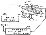
제8도 및 제9도에 도시한 실시예에서, 근시 교정 절산 과정은(인덱싱 축(50')을 중심으로 마스킹 원판(50)(masking disc)을 점차로 각도 인덱스 이동시킴으로써 순차적으로 개구부 면적인 변화하는 마스크 개구부들을 이동시켜 인덱스 작업을 수행하여 이루어지는데, 원판(50)은 주연부에 분포된 최대 개구부(51)로부터 최소 개구부(52)까지의 일련의 마스크 개구부들을 갖는다. 개구부(51)에 대한 참조 부호 53과 같은 반경 방향 표시는 소정의 개구부가 레이저 조사축(12)상에 정확한 위치로 인덱스되는 각을 나타낸다. 원판(50)은 환형 링(54)에 정착되는 것으로 도시하였는데, 상기 링(54)는 원판(50)을 중심에 키이(key) 묻힘 형태로 수납할 수 있는 대응된 구멍을 가지며, 링(54)는 회전 구동신호발생기(56)의 제어에 따라 적절한 구동기(55)에 의해 연부에서 구동된다. 또한 프로그램 가능한 마이크로프로세서(57)은 레이저 펄스들을 소정의 마스크 개구부들에 예정대로 배당시키도록 회전 인덱스 구동기(55-56)을 제어하여, 광변환기(59)가 각각의 주어진 마스크 개구부들의 특정 반경 방향 표시선과 정렬되는 상태를 추종할 때 동기 라인(58)을 통한 레이저 펄스 동기화에 의해 필요한 각막의 형상으로 교정한다.In the embodiment shown in Figs. 8 and 9, the myopia correcting cutting process (sequentially changing the opening area by moving the masking disc 50 (masking disc) gradually with respect to the indexing axis 50 ' The disk 50 has a series of mask openings from the largest opening 51 to the smallest opening 52 distributed in the periphery of the mask opening. A radial indication, such as 53, indicates the angle at which a predetermined opening is indexed to the correct position on the
제10도 및 11도는 각막의 전방 외부면의 곡률을 증가시켜 새로운 윤곽(61)(제10도)를 형성하는데 즉, 원시 교정을 위해 각막(60)을 절삭 교정하는데 제8도의 장치를 사용하는 것을 도시한 것이다. 이는 제8도에 도시한 원판(50) 대신에 새로운 원판(62)를 사용함으로써 수행할 수 있다. 원판(62)에서, (참조 부호 63과 같은) 각각의 막 각도 표시 위치에서의 기본적인 개구부의 한계, 즉 3.5nm의 반경을 갖는 개구부가 원주상으로 분포된 순차적인 환형 개구부들의 각각의 외측 연부가 되며, 환형 개구부는 순차적으로 직경이 변하는 중앙의 불투명 마스킹 점에 의해 형성된다. 따라서, 반경 방향 표시(63)에서의 가장 작은 마스크 환형부(63')에서, 중앙 불투명점의 원의 직경은 거의 기본적인 한계 개구부의 직경과 거의 일치하게 되어, 제1의 가장 얇은 환형부(63')을 형성하게 된다. 다음 표시(64)에서, 약간 두꺼운 환형부(64')은 약간 작은 면적의 중앙 불투명 점에 의해 결정된다. 이러한 수차적인 단계는 [원판(62)의 인덱스 축을 중심으로 하여] 중심 불투명 마스킹 원이 가장 작은 직경이 되는 각 위치(65)에서의 가장 큰 개구 환형부(65')에 도달할 때까지 등각도록 연속적으로 증가시켜 간다. 마스크(62)를 제8도에 도시한 위치 설정 및 제어 장치와 결합하여 사용할 때에, 마이크로프로세서(57)은 레이저 펄스들을 특정 크기의 환형 마스크 개구부들에 설정하여 큰 반경에서 가장 큰 각막의 융제 침투가 이루어지도록 하고, 가장 작은 반경에서 가장 작은 침투가 이루어지도록 하여 곡률이 감소된 교정된 윤곽(61)을 형성하게 된다.10 and 11 increase the curvature of the anterior outer surface of the cornea to form a new contour 61 (Fig. 10), i.e. using the apparatus of Fig. 8 to cut and correct the cornea 60 for primitive correction. It is shown. This can be done by using a
제12도, 13도 및 14도의 장치들은, 전술한 본 발명의 원리들을 원시 교정, 또는 도시한 바와 같이 근시 교정을 할 수 있는 필요한 곡률의 프레넬(Fresnel)형의 분포를 얻기 위해 각막을 절삭 교정하는데 사용하는 것을 도시한 것이다. 전술한 시술(즉 프레넬형)은 의사가 판단할 때 단일의 매끄러운 교정 곡면을 형성하게 되면 가장 깊은 절삭을 수행하는 부분에서 조직을 너무 많이 제거해야 하는 경우에 행해진다. 너무 깊이 절삭하는 것을 피하기 위해, 제12도 및 13도는 제4도에서 곡면(31)[제13도의 곡면(71)]과 같이 곡률이 감소된 곡면을 참조 부호 70으로 한정된 영역내에서 환형 중가부로서 형성한다. 상기 환형부 중의 외측 환형부(72)에서, 절삭 깊이 및 곡률은(프레넬 단계없이)연속된 곡면(71)을 형성할 때 수행하는 것과 같이 정밀하다. 그러나, 중간 환형부(73)은 절삭되는 각막의 양을 작게하면서 연속된 곡면(71)을 효과적으로 형성한다. 마지막으로, 내측 원형부(74)는 각막 조직을 최소로 제거하면서 곡면(71)을 효과적으로 완성한다.The apparatus of FIGS. 12, 13 and 14 cuts the cornea to obtain a Fresnel-shaped distribution of the necessary curvature, which is capable of primitive correction, or myopia correction as shown above. It is used to calibrate. The procedure described above (ie Fresnel type) is performed when the doctor judges that forming a single smooth correction curve requires removing too much tissue at the deepest part of the cut. To avoid cutting too deeply, FIGS. 12 and 13 show an annular heavy weight within an area defined by
중심에서의 조직 제거 정도는 제12도 및 13도의 프레넬 절삭 원형부(74)의 경우 참조 부호 △74로 나타내었는데, 이는 매끄럽게 진행하여 교정되는 단일 곡면(71)로 동일한 시력 교정을 행하는데 필요한 최대 절삭 깊이 △71과 비교하여 볼 때는 작은 양이 된다. 제14도는 제8도에 도시한 원판(50) 대신에 제8도의 시스템과 조화될 수 있는 형태의 인덱스 가능한 회전 마스킹 원판(75)를 도시한 것으로서, 이에 의해 상이한 환형부(72, 73, 74)로 특징지워지는 프레넬형 절삭을 수행할 수 있다. 가장 큰 마스크 환형부(76)(참조부호 76' 위치)에서부터 시작하여 원판(75)의 처음 120° 구간에서, 환형 마스크 개구부들의 반경은 점진적으로 감소하는데, 이는 중심 마스크 점의 크기는 일정한데 비해 외부원의 직경이 순차적으로 축소하기 때문이다. 프로그램 가능한 마이크로프로세서(57)(제8도)는 상기 제1구간의 환형 마스크 개구부들을 프로그램된 상태로 분포시킴으로써 레이저의 펄스의 발사 위치 설정을 조절하여, 외부 환형부(72)내에 곡면(71)을 형성하게 된다. 마스크 원판(75)의 (도시되지 않은) 제2구간에 마찬가지로 환형 마스크 개구부들을 순차적으로 배치하여, 중간 환형부(73)내에 곡면(71')을 형성한다. 마지막으로 마스크 개구부 직경이 가장 큰 개구부(원 74) 부분으로부터 시작하여 제3구간을 통해(제1구간의) 위치(76')에 인합한 위치(78')에서의 가장 작은 개구부(78)까지 점진적으로 축소되는 인덱스 가능한 순차적인 원형 개구부들을 통해 축(12)상으로 프로그램된 레이저 발사를 행함으로써 내부 원형부(74)내에 곡면(71")을 형성하게 된다.The degree of tissue removal at the center is indicated by the reference numeral Δ74 for the Fresnel cutting
제15도 및 16도는 장방형 비임 부분을 갖는 융제 레이저 펄스를 사용하되, 비임 부분의 폭을 변화시켜 원통형상의 누적되는 융제 침투를 수행하여 난시를 교정하는 본 발명의 가변 간극 및 인덱스 가능한 마스크 기술을 도시한 것이다. 이는 가변 폭을 갖는 슬리트 또는 격막을 사용하여 레이저 비임을 차단(마스킹)함으로써 수행할 수 있으며, (특정 눈의 난시 상태의 원통형 디옵터 강도 및 각을 측정한 결과에 따라) 슬리트의 긴 변이 위치하는 방향을 선택적으로 회전시키는 능력에 의해서도 수행될 수 있으나, 제15도에 도시한 형태에서 마스크는 폭이 점진적으로 변하는 일련의 장방형 슬리트 개구부들을 갖는 가늘고 긴 대편(80)이다. 제16도에 부분적으로 도시한 바와 같이, 이들 개구부들은 가장 큰 면적의 개구부(81)로부터 가장 작은 면적의 개구부(81')으로 순차적으로 축소되며, 상기 개구부들의 대칭 중심축들은 개구부(81)의 경우에 참조 부호 82에서와 같은 표시로 나타내며, 이들 표시들은 동일 간격으로 되는 것이 적합하다.15 and 16 illustrate the variable gap and indexable mask technology of the present invention using ablative laser pulses having a rectangular beam portion, wherein the width of the beam portion is varied to correct cylindrical astigmatism by performing cumulative flux penetration in the cylindrical form. It is. This can be done by blocking (masking) the laser beam using slits or diaphragms with varying widths, and the position of the long side of the slits (depending on the measurement of the cylindrical diopter intensity and angle of a particular astigmatism state). It may also be performed by the ability to selectively rotate the direction of the direction of the drawing, but in the form shown in FIG. 15, the mask is an elongated large piece 80 having a series of rectangular slits openings that gradually change in width. As shown in part in FIG. 16, these openings are sequentially reduced from the largest area opening 81 to the smallest area opening 81 ', with the symmetric center axes of the openings 81 In this case, it is indicated by the same marks as in
대편(80)은 회전가능한 마스크지지 원판 또는 링(84)의 일부를 형성하는 안내 장치(83)에 의해 활주 안내되며, 안내 장치(83)은 슬로트의 종방향 대칭축(86)을 링(84)의 직경 방향으로 위치시킨다. 수동조절장치(85)는 링(84)의 연부를 구동시키도록 결합되어 있어 링(84) 연부의 방위 표시에 대한 고정된 표시기(87)의 위치를 관찰함으로써 대표(80)의 [레이저 조사 축(12)를 중심으로 한] 각 위치를 선택한다. 2방향성 활주 구동신호발생기(88)은, 마이크로프로세서(89)의 제어에 의해, 인덱스된 특정 마스크 개구부에 적용할 수 있는 표시(82)를 추적하는 광변환기(90)에 의해 적절히 동기화하여, 레이저 펄스에 의해 대편(80) 위치를 조정함으로써, 각각의 마스크 개구부는 레이저 비임 조사 축(12)상에 확실하게 위치하게 된다.The large piece 80 is slid by a
난시를 교정하고 구형도 수정해야 할 눈에 대한 레이저 시술에 본 발명을 사용할 시에, 제15도 및 16도와 관련하여 설명한 난시 교정을 먼저 수행하는 것이 좋다. 이는 난시 오차가 구형 오차에 비해서는 대개 심각하지 않기 때문에, 차후에 수행하는 구형 교정과정에 비해 원통형 곡률 융제에 의한 디옵터 교정이 적기 때문이다. 또한, 제1과정에 의한 난시의 감소 또는 완전한 교정은 각막의 전방 외부면을 구형면으로 형성하게 되는데, 이는 특히 본 발명의 경우와 같이 모든 융제 레이저 발사가(마스크 개구부를 사용하여 발사하는가에 상관없이) 시술할 눈의 광학축의 중심에 정확하게 정렬되는 경우에, (근시 또는 원시의 특성을 가질 때) 정시안이 되도록 적절한 형상으로 절삭 교정될 수 있다.When using the present invention in laser surgery for an eye for which astigmatism should be corrected and spherical corrected, it is advisable to first perform the astigmatism correction described with reference to FIGS. 15 and 16. This is because the astigmatism error is usually less severe than the spherical error, and thus the diopter correction due to the cylindrical curvature flux is less than that of the subsequent correction process. In addition, the reduction or complete correction of the astigmatism by the first procedure will result in the formation of the anterior outer surface of the cornea into a spherical surface, which, in particular, does not matter whether all ablative laser firings are fired (using a mask opening), as in the case of the present invention. Without correcting), it can be cut and corrected to an appropriate shape so as to be normal eyes (when it has a myopia or hyperopia) when correctly aligned to the center of the optical axis of the eye to be treated.
각막 조직의 제거 깊이를 가변적으로 할 수 있는 특징(제4도 및 10도) 이외에도, 본 발명은 각막 이식 수술을 위한 각막 수납부 준비시에 각막의 단일 면적 전체에 대해 균일한 깊이로 제거를 행할 수 있다. 제17도 및 18도에서, 눈(11)의 각막은 직경 7mm인 동일 면적으로 마스크된 레이저 펄스가 연속적으로 조사되는데, 이 경우, 연속적인 펄스형 레이저 발사는 이식될 각막을 수납 및 위치시키기 위한 만입된 바닥 곡면 또는 절삭된 기부(95)를 형성하게 된다. 다른 방법으로, 제17도 및 제18도에서, 눈(11)의 각막은(a) 일정한 직경 D상의 동일 마스크를 통해, 또한 (b) 소정의 레이저 비임 조사 기간(노출 시간)에 필요한 침투 깊이를 얻을 수 있는 융제 침투율로 융제할 수 있게 하는 세기의 일정한(CW) 레이저에 노출될 수 있다.In addition to the features of varying the depth of removal of corneal tissue (FIGS. 4 and 10), the present invention provides a uniform depth to a single area of the cornea when preparing the corneal compartment for corneal transplant surgery. Can be. 17 and 18, the cornea of the eye 11 is successively irradiated with the same area masked laser pulses of 7 mm in diameter, in which case continuous pulsed laser firing is used to receive and position the cornea to be implanted. An indented bottom curved or cut
각막 이식 과정과 관련해서, 전술한 장치는 요홈(95)내에 삽입되는 각막 삽입부를 준비하는 경우에 더욱 유용하다. 기증된 눈은 제2도에 참조 부호 18로 표시한 바와 같은 고정부에 가역적으로 고정시키는데, 여기에서 "가역적(reversible)"이라 함은 플랜지(25)의 장착 방법에 따라, 기증된 눈의 상피 또는 내피가 레이저 비임(12)에 대해 상향으로 노출되도록 위치될 수 있음을 의미하는데, 기증된 눈의 내피가 상향 노출되는 후자의 경우에 각막 공막 고정 및 각막 시술시 필요하지 않은 홍채 및 다른 부분들이 우선 제거됨을 이해할 수 있다. 양호한 과정의 일예에서는 먼저 기증된 각막의 오모한 내측면을 레이저에 노출시키는데, 이러한 과정은 기증된 눈의 기질내에 균일한 깊이로 적어도 조직을 제거하기에 충분한 [요홈(95)의 영역을 초과하는 완전한 원형 영역에 설정 기간 동안의 CW 노출에 의해 또는 배증 펄스식 레이저 발사에 의해 달성됨] 정도까지 이루어지고, 그 다음에 고정구(18)( 및 부분 가공된 각막편)을 발전시켜, 기증된 각막의 볼록한 외부면을 레이저 작용에 노출시킨다. 외측면에 대한 레이저의 작용은 두 단계로 구성된다. 먼저, [요홈(95)의 직경을 초과하는] 완전한 원형 영역에 배증 레이저 펄스를 소정 시간의 CW 노출을 수행하여, 적어도 상피를 요홈(95)의 두께 T2를 초과하는 이식 두께 T1을 형성하는 깊이까지 제거한다.With regard to the corneal transplantation process, the device described above is more useful for preparing corneal inserts to be inserted into the
그 다음에, (도시되지 않았으나 본 출원인의 상기한 미합중국 특허 출원 제552, 983호에 기재된 형태의) 조사기(scanner)를 선 절삭 방식으로 작동시켜, 완전한 원형 절개부가 절삭될 때까지 원형 요홈(95)내에 정확하게 수납되도록 설정된 원의 원주를 따라 레이저 펄스를 연속적으로 조사하여 이식부를 마련한다. 이식시에, 기증된 기질을 내피가 전혀 없이 환자의 준비된 기질과 내피가 전혀 없이 접촉되도록 위치시키고 다음에 이식부를 봉합한다. 다음에, 봉합사를 제거하면, 눈(11)의 외부면 및 그 이식부(96)은 제18도에 도시한 형태가 되는데, 여기에서 이식부는 환자의 인접된 각막 부분을 지나 돌출되는데, 이러한 이식부의 돌출부는 환자의 눈의 절삭되지 않은 인접한 조직과 일치되도록 전술한 레이저 절삭 과정에 의해 제거되어 완성된 윤곽(97)을 마련하게 된다. 의사의 결정에 따라 마무리 절삭 과정은 눈의 시력에 소정의 영향을 주게하거나 주지 않게 하는 곡률로 수행할 수 있다.Then, a notch (not shown but described in Applicant's aforementioned US patent application No. 552, 983) is operated in a line cutting manner to produce a
전술한 방법 및 장치는 본 발명의 목적을 수행할 수 있도록 하고 각막의 곡률의 이상에 따른 눈의 이상을 교정할 수 있는 제어가 용이한 방법으로 마련하게 된다. 레이저 비임 작용에 의한 융제 침투 작용은 각막의 전체 두께에 비교적 조직에 손상을 주지 않으며, 침투 깊이에 관계없이, 자연적인 신체 기능에 의해 시술이 끝난후 수일 내에 절삭된 부분에 보호 상피가 형성되게 된다. 소정의 크기 및 형태의 펄스의 수와 관련한 레이저 비임 크기 및 형태(원형, 환형 또는 장방형)를 프로그램 가능하게 조정하는 것은 곡률의 변화를 예측 및 제어할 수 있게 해주어, 원통형 오차 및/또는 구형 오차를 감소 또는 제거할 수 있어, 환자의 편안함과 편리함을 증진시키게 된다.The above-described method and apparatus are provided in an easy-to-control method that enables the purpose of the present invention to be corrected and to correct the abnormality of the eye according to the abnormality of the curvature of the cornea. Ablative penetrating action by the laser beam action does not damage tissues relatively to the entire thickness of the cornea and, regardless of the depth of penetration, the protective epithelium is formed in the cut part within a few days after the procedure by natural body function. . Programmable adjustment of the laser beam size and shape (circular, annular, or rectangular) with respect to the number of pulses of a given size and shape allows for predicting and controlling changes in curvature, thereby reducing cylindrical and / or spherical errors. It can be reduced or eliminated to enhance patient comfort and convenience.
이제까지 본 발명을 예시적인 실시예 및 방법에 대해 상술하였으나, 본 발명의 분야를 이탈하지 않는 범위내에서 변형을 가하는 것도 가능하다. 예컨대, 난시 교정을 하기 위한 각을 설정하는 전술한 수동장치(85)는 난시 교정각을 자동적으로 설정할 수 있는 장치로 할 수 있으며, 자동 구동을 위한 각 입력 데이터는 본 발명자의 1985년 6월 16일자 미합중국 특허 출원 제691, 923호에 기술된 진단 시스템 또는 방법에 의해 얻을 수 있다.While the present invention has been described above with respect to exemplary embodiments and methods, it is possible to add modifications without departing from the scope of the present invention. For example, the above-described
또한, 예컨대 난시를 교정하기 위한 원통형 절삭에는 반드시 제15도 및 16도에 도시한 인덱스 가능한 슬로트 기술을 사용해야 할 필요는 없다. 제1변형(제19도)으로서, 슬로트 폭의 변경은 슬로트 폭 구동장치(100)의 마이크로프로세서 제어에 의해 레이저 비임의 중심축(12)상에 항상 중심이 맞춰지는 가변 폭 개구부를 갖는 대향된 측면판(101-102)를 차동 구동시켜 전기 기계적으로 수행할 수 있는데, 판(101-102)는 난시 교정하는 각으로 [양방향 화살표(103)으로 표시한 바와 같이] 회전을 조정할 수 있는 환형 기부(104)에 활주 가능하게 장착된다. 제2변형(제20도)으로서, 마이크로프로세서 출력으로 원통형 줌 렌즈(105)를 [양방향 화살표 (106)으로 표시한 바와 같이]모터 구동시켜, 조사된 레이저 비임(12)의 형태를 가변 폭을 갖는 직선으로 하는데, 상기 직선은 줌 렌즈(105)용의 환형 장착부의 림(108)을 연부 구동시키는 구동기(107)을 사용하여 난시를 교정할 수 있는 각으로 고정할 수가 있다.In addition, for example, cylindrical cutting for correcting astigmatism does not necessarily require the use of the indexable slot techniques shown in FIGS. 15 and 16. As a first variant (Fig. 19), the change in slot width has a variable width opening which is always centered on the
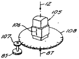
제21도 내지 26도는 레이저 융제 과정으로 각막 곡률을 수정하기 위한 순차적인 레이저 조사점의 크기를 반사 기술을 사용하여 형성하는 본 발명의 다른 양태를 도시한 것이다. 상기 도면들에는 제6도, 7도, 8도, 9도, 11도 및 14도에 도시한 부분들과 대응된 부분들이 존재하기 때문에, 동일한 참조 번호를 사용하되 100단위로 표시하였다.21 to 26 show another embodiment of the present invention for forming the size of sequential laser irradiation points for correcting corneal curvature using a laser ablation process using reflection techniques. Since the drawings correspond to the parts shown in FIGS. 6, 7, 8, 9, 11, and 14, the same reference numerals are used to denote 100 units.
제21도 및 22도에 도시한 실시예에서, 수정으로 된 투명판(135)는 그 장축이 2차원(X-Y)적으로 인덱스 가능한 투명판(135)의 각각의 위치에서 평행한 상태로 판의 중심에 위치되는 방위를 갖는 일련의 타원 반사 영역들을 갖는다. 투명판(135)상의 타원형 반사면의 격자형 구조에 있어서, 타원형의 크기는 점진적으로 증가되어 있다. 따라서, 반사 타원면의 제1열은 반사 영역(136)에서부터 반사 영역(136')까지 그 크기가 감소되고, 다음열은 반사 영역(137)에서 시작하여 반사 영역(137')까지 그 크기가 감소되고, 제3열에서는 반사 영역(138)에서 반사 영역(138')까지 그 크기가 감소되며, 마지막 열은 반사 영역(139)로부터 가장 작은 반사 영역(139')까지 그 크기가 감소된다. 투명판(135)의 인덱싱 변위를 지지할 시에는 그 반사면이 레이저 출력 비임의 중심축(12')에 대해 경사지게 지지하는데, 경사 정도는 특정 타원형 반사 영역의 중심이 비임의 중심축(12')과 교차되도록 인덱스될 때 각각의 타원형의 장축이 비임의 중심축(12')에 대해 45°의 각을 이루도록 하며, 동시에, 특정 타원형 반사 영역의 중심이 비임의 중심축(12')과 교차되도록 정렬될 때 타원형의 단축은 비임의 중심축(12')과 90°를 이루며, 장축/단축의 경간비![]()
![]()
인덱싱 투명판(135)의 완전한 2-좌표 프로그램 내에서의 제21도에 도시한 장치의 자동 작동은 시술할 원형 각막 부분의 중심에 가장 높은 밀도의 융제 에너지를 전달하게 되는데, 이 에너지 밀도는 눈의 광학축으로부터의 반경이 증가할수록 감소된다. 따라서 곡면 변화는 근시 교정 특성을 나타내게 된다.The automatic operation of the apparatus shown in FIG. 21 within the complete two-coordinate program of the indexing
제23도 및 24도에 도시한 실시예는 제8도 및 9도에 도시한 실시예와 대응된 것으로서, 주연부에 부포된 형태의 타원형 반사면은 인덱스 가능한 디스크 또는 원판(150) 상에 위치하며, 원판(150)은 수정으로 구성하여 투명하게 하는 것이 좋다. 적합하게는 모든 타원형들의 중심은 인덱스 축(150')을 중심으로 하는 기하적인 단일 원 상에 위치하는 것이 좋으며, 인덱스 축(150')은 레이저 비임(12)의 축 및 (반사된) 눈으로 향하는 비임의 중심축(12') 사이의 직각을 이등분하도록 방위 설정되고, 비임의 중심축(12')는 눈(11)의 광학축과 정렬된다. 또한, 각각의 타원형 반사면의 장축은 원판(150)의 인덱싱 중심의 반경 방향으로 향하게 하고, 모든 타원형 반사면의 장축/단축 비는![]()
![]()
제25도에 부분적으로 도시한 것은 [제24도의 원판(150) 대신에] 다른 원형 반사판(162)로 대체한 것이며, 회전 인덱싱 및 레이저 펄스화를 마이크로프로세서로 프로그래밍함으로써 제10도에 도시한 바와 같이 각막 곡률을 변경시키는 원시 교정을 수행하게 된다. 제25도에 도시한 타원형 반사면들은 일정한 주연부를 갖는 타원형 환형부들이 일정 각도로 이격되어 연속되고, 인덱스 위치(163)에서의 반경 방향으로 가장 얇은 타원형(163')으로부터 인덱스 위치(165)에서의 반경 방향으로 가장 두꺼운 타원형(165')까지 그 범위가 순차적으로 되어 있다. 다시 말하면 제25도에 도시한 타원형 반사면의 순차적인 상태는 외경은 동일하고 내경은 가변적인 환형 조사를 제공하고, 판(162)의 단일의 인덱스 회전을 통해 외경에서는 각막에 최대 융제 침투를 제공하게 되고, 눈(11)은 광학축을 중심으로 한 반경이 감소됨에 따라 융제 침투가 감소되는 것을 말한다. 모든 타원형 반사면에 있어서, 장축/단축 비는![]()
![]()
제26도에 도시한 장치는 제12도 및 13도에 도시한 장치에 제24도 및 25도에 도시한 반사 원리를 사용하여 각막을 절삭하여 프레넬 형태의 곡면 분포를 얻기 위한 것으로서, 이는 제15도에 도시한 바와 같이 원시 교정 또는 도시한 바와 같이 근시 교정을 할 수 있다. 너무 깊게 융제 침투를 수행하는 것을 피하기 위해 제4도에서의 참조 부호 31(제13도에서의 일점쇄선 71)로 표시한 바와 같은 최종 절삭 곡면은 참조 부호 70으로 한정된 원형 부분 내에서 환형 증가부들을 마련함으로써 수행되며, 곡면(71)은 단계(72-73-74)를 통해 형성된다.The device shown in FIG. 26 is for cutting the cornea using the reflection principle shown in FIGS. 24 and 25 in the device shown in FIGS. 12 and 13 to obtain a Fresnel-shaped curved distribution. Hyperopia correction can be performed as shown in FIG. 15 or hyperopia correction as shown. In order to avoid carrying out the flux penetration too deep, the final cutting surface as indicated by
제26도에 도시한 바와 같이, 투명 원판(175)는 제23도의 원판(150)을 대체한 것으로서 투명 원판(175)에는 일정한 크기의 내부 한계 타원형(177)을 기초로 하고 위치(176')에서의 가장 크고 가장 두꺼운 타원형 환형부(176)으로부터 시작되어 시계방향으로 크기 및 두께가 점진적으로 감소되는 다음 타원형 환형부로 변화되는 일정한 각도록 단계적으로 이행되는 타원형 반사면 환형부들이 마련된다. 도시한 3단계 윤곽(72-73-74)를 제공하기 위해, 동일한 내부 한계 타원형(177)을 기초로 한 타원형 반사면 환형부들은 원판(175)의 처음의 120° 구간에 분포되며, 외부 타원형 주연부는(도시되지 않은)반경 방향으로 가장 얇은 마지막 타원형까지 점진적으로 축소되며, 프로그램 가능한 마이크로프로세서(57)(제8도)는 제1구간의 타원형 반사면들의 프로그램된 분포를 이용하여 레이저 펄스 발사의 위치 설정을 제어하는 기능을 하여, 외측 환형부(72)내에 곡면(71)을 융제 성형한다. 원판(175)의 (도시되지 않은) 다음 120° 구간에 동일하게 인덱스 가능한 일련의 동일한 타원형 반사면들을 마련하여, 중간 환형부(73) 내에 곡면(71')을 형성한다. 마지막으로, [도시되지 않았지만, 중심 원형부(74)의 직경과 동일한]가장 큰 단축 경간을 갖는 타원형으로부터 제3의 120°구간을 통해 제1구간의 위치(176')에 인접한 위치(178')에서의 가장 작은 타원형 반사면(178)까지 감소되는, 타원형 면적이 점진적으로 축소되는 인덱스가능한 일련의 반사면을 통해 프로그램된 레이저 비임(12')을 조사함으로써 내측 원형부(74) 내에 곡면(71")을 형성한다.As shown in FIG. 26, the
적절하게 프로그램된 펄스형 레이저가 비임의 중심축(12')으로 전달되는 상황에서 원판(175)를 완전히 1회전 시킴으로써, 프레넬 단계(72-73-74)를 연속적으로 성형할 수 있다. 마이크로 회로 기술에서 유용한 매우 정확한 광 감소 및 금속 증착 기술을 사용함으로써, (도시되지 않은) 단일 원판의 각각의 인덱스된 단계가 완전한 프레넬형 융제 형태의 환형부들을 점진적으로 성형하는데 유효한 것을 알 수 있다. 상기 결과를 얻기 위한 타원형 반사면을 형성하기 위해, 제27도는 근시 교정의 경우에 모든 타원형 반사면의 단축 크기의 변화 경로를 대략 도시하였으며, 제28도는 원시 교정시의 모든 타원형 반사면의 단축 크기의 변화 경로를 대략 도시한 것이다.Fresnel steps 72-73-74 can be continuously formed by rotating the
제27도에서, [제23도의 원판(150) 대신에 사용할 수 있는] 소정의 원판의 전체 360°각 범위를 360°/n 간격으로 인덱스가능한 단계의 필요한 수(n)으로 나누고, 매 방위 분포 증가시마다 세로 좌표선(예컨데, 참조 부호 120)을 도시함으로써, 각각의 특정 인덱스 위치에서 관련된 복수의 타원형 반사면들의 각각에 필요한 단축 경간을 확정하는 교점[예컨데, 위치(120)에서의 a-b-c-d-e]이 5개소에서 얻어진다. 제27도에 도시한 관계의 결과는 (영역 72-73-74의 경우) 모든 외경이 변하지만, 내경은 일정하기 때문에 근시 교정과정이 된다. 한편, 제28도에 도시한 관계를 결과는 위치(121)에서의 교점(a'-b'-c'-d'-e')를 보면 알 수 있듯이(도시되지 않은, 영역 72'-73'-74'의 경우) 모든 내경은 변하나, 외경은 일정하게 유지되므로 원시 교정 과정이 된다.In FIG. 27, the entire 360 ° angle range of a given disc (which may be used in place of the
전술한 바와 같이, 인덱스된 반사면을 통해 레이저를 조사하는 것은 기본적으로 구면의 곡률 교정에 대한 것으로서, 경우에 따라 원시 또는 근시를 교정하게 된다. 그러나, 마찬가지 원리를 난시 교정에도 적용할 수 있으며, 이 경우에는 순차적으로 인덱스되는 반사면은 장방형으로 하고, 폭을 순차적으로 변화시키고, 순차적인 순서에서 가장 좁은 장방형의 중심 장축의 양 측면에 대칭형이 되게 한다. 따라서 제16도에 도시한 도면은 이러한 형태를 나타낸 것으로 간주할 수 있으며, 여기에서 인덱스가능한 대편(80)은 (수평판과 같은) 투명판으로 하고 일련의 장방형(81) 내지 (81')은 하나의 중심선(82)에서 다음 중심선까지는 지시하는 중심선간의 간격이 일정한 반사면이 되고 레이저 비임의 중심축(12')은 각각의 인덱스된 위치에서 중심 정렬축(86)교 교차되도록 향한다. 대편(80)이 안내링(84) 상에서 지지되고 제23도의 원판(150)에 대해 기술한 바와 같이 경사면에 위치하는 경우에, (참조 부호 85에서의 조정에 의해 설정된) 안내링(84)의 각 위치는 눈에 투사 되는 장방형 점들의 폭 변화의 범위를 나타내나, 모든 선택된 각 위치에서 눈에 대한 필요한 누적 용제 과정은 마이크로프로세서 내에 적절한 각 보정값을 기억시킴으로써 수행할 수 있는데, 상기 보정값은 방위각의 간단한 삼각 함수가 된다.As described above, irradiating the laser through the indexed reflective surface is basically for the curvature correction of the spherical surface, which in some cases corrects hyperopia or myopia. However, the same principle can be applied to astigmatism correction, in which case the reflective surfaces sequentially indexed are rectangular, the widths are sequentially changed, and symmetrical shapes are provided on both sides of the central long axis of the narrowest rectangle in the sequential order. To be. Thus, the figure shown in FIG. 16 may be regarded as such a form, where the indexable piece 80 is a transparent plate (such as a horizontal plate) and a series of rectangles 81 to 81 ' From one
본 발명의 전술한 반사면을 사용함에 있어서, 반사면의 개개의 형태는 (비임의 중심축(12') 상의] 레이저 비임 단면적의 일부에만 작용하며, 반사면들이(수정판과 같은) 투명판 상에 장착되는가 또는 형성되는가에 관계없이 또 다른 방법으로 장착되는가에 관계없이, 반사되지 않는 레이저 비임 출력의 소정의 발사 부분은 비임의 중심축(12')상에 계속 전달되게 됨을 이해해야 한다. 이와 같이 계속 전달되는 에너지는 수술에 사용되지 않으며(도시되지 않은)적절한 수단에 의해 차단되거나 또는 산란된다.In using the above-described reflective surface of the present invention, the individual shape of the reflective surface acts only on a portion of the laser beam cross-sectional area (on the beam's central axis 12 '), and the reflective surfaces (such as quartz plates) Regardless of whether it is mounted on or formed in another way, it is to be understood that the predetermined firing portion of the non-reflective laser beam output will continue to be transmitted on the center axis 12 'of the beam. The energy delivered continuously is not used for surgery (not shown) and is blocked or scattered by appropriate means.
상술한 원시 교정에 사용하는 응용예로서, 제10도는 광학 교정 부분(표면 61)의 반경 방향 외측 한계에서 각막내로 가장 깊게 침투시켜 필요한 디옵터 교정의 크기에 비례하는 깊이를 비교적 예리한 원형 연부를 형성한다. 이와 같이 예리한 연부는 수술된 부분(61)에 상피 재성장에 대한 문제를 야기시키는데, 상피 재성장이 적절히 이루어지도록 하기 위해서는 예리한 연부 또는 예리한 불연속부에 의해 중단되지 않는 연속된 면을 제공하는 것이 필요하다. 이와 같은 예리한 연부의 형성을 방지하기 위해, 발사되는 레이저 비임(12)는 원시 곡면 교정을 행하는 단면적보다는 큰 단면적으로 되어, 곡면 교정 원을 감싸고 또한 이에 연속되는 유연한 형상의 외부 대환을 제공해야 된다. 제29도에서, 광학 교정된 표면(61)은 곡면 교정 Rcc의 외부곡률을 갖는 것으로 도시하였으며 그 직경은 2Rcc이며, 유연한 형태의 외부 대환은 반경방향 두께 △R을 갖는 것으로 도시하였으며, 레이저 비임의 전체 조사 면적은 직경 2(Rcc+△R)이 된다. 상술한 유연화작용은 곡면 교정된 융발 부분(61)을 융발되지 않은 외부 각막 부분에 연결하는 점선으로 제29도에 도시한 바와 같이 △R내에 부드럽게 경사진 전이 형상을 이룬다.As an application for use in the primitive correction described above, Figure 10 penetrates deepest into the cornea at the radially outer limit of the optical correction portion (surface 61) to form a relatively sharp circular edge with a depth proportional to the size of the diopter correction required. . Such sharp edges cause problems with epithelial regrowth in the
특히, 제30도는 제11도와 관련하여 설명한 특성을 가지나 제29도의 유연한 형태 특성과 결합된 인덱스가능한 회전 마스킹 디스크(162')을 도시하고 있다. 제30도에 표시한 치수 표시는 제1인덱스 위치(163)에서 내경이 중심 마스킹 원(163')의 외경에 의해 결정되도록 발사된 레이저 점이 얇은 대환들이 되어짐을 나타내며, 상기 외부 마스킹 직경은 교정된 곡면 표면(61)(제29도)의 반경의 2배를 의미하는 2Rcc로 표시되어 있고, 순차적인 인덱스된 부분(164), (165)에서, 중심 마스킹 원(164', 165')은 점차 축소된 직경 2Rcc' 및 2Rcc"으로 각각 표시되어 있다. 또한, 위 순차적인 인덱스된 부분(164, 165)에서 발사된 대환 비임(12)의 외경은 제1축소 직경(2Rcc+△R'), 다음 축소 직경 2(Rcc+△R")으로 점차 축소됨을 나타낸다. 이와 같은 점진적인 직경 축소는 순차적인 감소로 계속되며, 디스크(162)의 인덱싱 변위에서, 최소 중심 마스킹 원(166')을 갖는 최종 인덱스 위치(166)에서 최고가 되며, 가장 축소된 외경(2Rcc+![]()
![]()
디스크(162)의 인덱스 위치의 수 n을 충분히 함으로써, 각막 침투의 누적은 광학적으로 교정된 표면(61)의 유연한 형태를 이루고, 또한 외부 전이 대환들도 유연한 형태로 되게 한다.By sufficient the number n of index positions of the disk 162, the accumulation of corneal infiltration results in a flexible form of the optically corrected
제31도는 마스크들을 순차적으로 인덱스하지 않고서도 전술한 유연한 대환 △R을 형성할 수 있는 장치의 개략도이다. 레이저(13)으로부터 발사되는 비임은 비임 익스펜더(170)에 의해 확장(expand)되어 단면이 확대된 주준된 비임으로 발사된다. 확장된 비임 단면 내의 중심에 고정 장착된 마스크 및 반사기의 역할을 하는 익스펜더(171)은 구동기(172)에 의해 제어되어 제30도에 순차적인 중심 마스크(163') 내지 (166')으로 도시한 바와 같은 직경 범위에 대응되게 외경의 범위를 가변시킨다. 제31도의 상이점은 외경 변화가 점진적으로 연속되게 변화하는 것이며, 이러한 결과를 얻기 위한 (171)에 있는 기계적 구조물은 우산 형태로 할수도 있으며, 그 외부면은 반사 특성을 갖고 있어 반사된 레이저 비임 에너지가 주변의 환형 흡수기(173)으로 굴절되도록 한다. 우산형 반사기 장치(171)의 확장 가능한 스커트 상에 초점이 맞추어져 있는 줌 렌즈 (174)는 모터 (175) 및 구동 회로 (176)에 의해 가역 구동될 수 있어 비임 출력(12', 12)를 2△R 범위에서 점진적으로 변화시킬 수 있으며, 한편, 가역 마스크 익스펜션 구동기(172)는 반사기 장치(171)의 스커트 직경을 변화시킨다. 마이크로프로세서(177)은 레이저(13)과 구동기(172) 및 줌 구동기(176)의 좌표를 제어하도록 연결되어 있다.Figure 31 is a schematic diagram of an apparatus capable of forming the above-mentioned flexible ring ΔR without sequentially indexing the masks. The beam emitted from the laser 13 is expanded by the
본 발명의 여러 실시예들에서의 직경 변화 및 노출 변화에 대한 설명에서, 이러한 변화는 대부분 제27도 및 28도에 도시한 바와 같이 선형으로 이루어진다. 그런, 주어진 레이저 비임 투사 광속밀도에서의 단위 시간당(각막 조직의)융발 침투깊이가 균일한 경우에, 노출시간에 대한 직경 변화는 제곱함수와 유사하며, 따라서 준포물선이 된다. 제32도는 근시(제32도) 상태를 감소 또는 제거하는 것인가, 또는 원시(제33도) 상태를 감소 또는 제거하는 것인가에 관계없이 상기 관계가 준포물선인 것을 나타내는 것이다.In the description of diameter change and exposure change in various embodiments of the invention, this change is mostly linear, as shown in FIGS. 27 and 28. In such a case, when the penetration depth per unit time (of corneal tissue) at a given laser beam projection light flux density is uniform, the change in diameter with respect to the exposure time is similar to the square function, thus becoming a parabola. FIG. 32 shows that the relationship is a quasi-parabola regardless of whether it reduces or eliminates myopia (FIG. 32) or reduces or eliminates primitive (FIG. 33).
제32도 및 33도에서, 상대 노출(각막에서의 레이저 비임 충돌의 누적된 광속 밀도)은 곡면 교정부의 외부 곡률인 Rcc 외측에서 곡률의 함수로 나타난다. 근시 교정(제32도)의 경우에, 최대 노출은 중심에서 이루어지며, 누적된 노출은 곡률 Rcc에서 최소(거의 제로)로 감소된다. 원시 교정의 경우에, 최대 노출은 곡률 Rcc에서 이루어지며, 누적된 노출은 중심에서 최소(거의 제로)로 감소되며, 또한 원시 교정의 경우에, 외부 대환 △R에서 최대 누적 노출로부터 최소 누적 노출로의 유연한 전이가 이루어짐을 주목해야 된다.In Figures 32 and 33, the relative exposure (cumulative beam density of the laser beam impact in the cornea) appears as a function of curvature outside Rcc, which is the outer curvature of the curvature. In the case of myopia correction (Figure 32), the maximum exposure is at the center and the accumulated exposure is reduced to the minimum (almost zero) at the curvature Rcc. In the case of primitive correction, the maximum exposure is at curvature Rcc, and the cumulative exposure is reduced to the minimum (almost zero) at the center, and in the case of primitive correction, from the maximum cumulative exposure to the minimum cumulative exposure in the outer ring ΔR. It should be noted that the flexible transition of.
대환 △R용의 제33도에 도시한 누적된 노출의 선형 감소는 대환내의 모든 점들에서의 최소 경사를 이루는데, 이는 수술로 행하는 각막의 최대 침투 깊이(즉 5mm직경인 원의 곡면 교정에 의한 10 디옵터 교정시의 100마이크론)에서는 선형 특성이 가장 양호하나, 5디옵터까지의 디옵터 교정의 경우의 보다 얕은 침투에시는 비선형(제33도에 △R에 걸져 점선으로 표시한 부분)에 의해 반경방향 외측 최대 침투의 곡률 Rcc로부터 각막의 처리 되지 않은 원래 형상까지 연속되게 유연한 곡률전이를 마련(반경 방향 경간 △R내에) 할 수 있게 된다.The linear decrease in the cumulative exposure shown in FIG. 33 for the annulus ΔR results in a minimal inclination at all points in the annulus, due to the maximum penetrating depth of the cornea (ie 5 mm diameter circle correction). The linear characteristic is the best at 100 microns at 10 diopter calibration, but the shallower penetration in the case of diopter calibration up to 5 diopters is nonlinear (parts shown as dashed lines across ΔR in Figure 33). Flexible curvature transitions (within radial span ΔR) can be provided continuously from the curvature Rcc of the maximum outward directional penetration to the untreated original shape of the cornea.
Claims (27)
Applications Claiming Priority (3)
| Application Number | Priority Date | Filing Date | Title |
|---|---|---|---|
| US891,285 | 1986-07-31 | ||
| US06/891,285 US4732148A (en) | 1983-11-17 | 1986-07-31 | Method for performing ophthalmic laser surgery |
| US891285 | 1986-07-31 |
Publications (2)
| Publication Number | Publication Date |
|---|---|
| KR880001271A KR880001271A (en) | 1988-04-22 |
| KR930011034B1 true KR930011034B1 (en) | 1993-11-20 |
Family
ID=25397909
Family Applications (1)
| Application Number | Title | Priority Date | Filing Date |
|---|---|---|---|
| KR1019870008309A KR930011034B1 (en) | 1986-07-31 | 1987-07-30 | Method and apparatus for performing ophthalmic laser surgery |
Country Status (8)
| Country | Link |
|---|---|
| US (1) | US4732148A (en) |
| EP (1) | EP0257836B2 (en) |
| JP (1) | JPS6373955A (en) |
| KR (1) | KR930011034B1 (en) |
| CA (1) | CA1300689C (en) |
| DE (1) | DE3782887T3 (en) |
| IL (1) | IL83185A (en) |
| ZA (1) | ZA875690B (en) |
Families Citing this family (278)
| Publication number | Priority date | Publication date | Assignee | Title |
|---|---|---|---|---|
| US5807379A (en) * | 1983-11-17 | 1998-09-15 | Visx, Incorporated | Ophthalmic method and apparatus for laser surgery of the cornea |
| US4773414A (en) * | 1983-11-17 | 1988-09-27 | Lri L.P. | Method of laser-sculpture of the optically used portion of the cornea |
| US5711762A (en) * | 1983-12-15 | 1998-01-27 | Visx, Incorporated | Laser surgery apparatus and method |
| US5108388B1 (en) * | 1983-12-15 | 2000-09-19 | Visx Inc | Laser surgery method |
| EP0152766A1 (en) * | 1984-01-24 | 1985-08-28 | Shiley Incorporated | Reduction of an arteriosclerotic lesion by selective absorption of electromagnetic energy in a component thereof |
| US6264648B1 (en) | 1985-07-29 | 2001-07-24 | Bausch & Lomb Incorporated | Corneal curvature modification via internal ablation |
| US4887019A (en) * | 1985-09-11 | 1989-12-12 | G. Rodenstock Instruments Gmbh | Device for the generation of a laser beam spot of adjustable size |
| US5423801A (en) * | 1986-03-19 | 1995-06-13 | Summit Technology, Inc. | Laser corneal surgery |
| US4856513A (en) * | 1987-03-09 | 1989-08-15 | Summit Technology, Inc. | Laser reprofiling systems and methods |
| GB8606821D0 (en) * | 1986-03-19 | 1986-04-23 | Pa Consulting Services | Corneal reprofiling |
| US5061840A (en) * | 1986-10-14 | 1991-10-29 | Allergan, Inc. | Manufacture of ophthalmic lenses by excimer laser |
| US5179262A (en) * | 1986-10-14 | 1993-01-12 | Allergan, Inc. | Manufacture of ophthalmic lenses by excimer laser |
| US5053171A (en) * | 1986-10-14 | 1991-10-01 | Allergan, Inc. | Manufacture of ophthalmic lenses by excimer laser |
| US4911711A (en) * | 1986-12-05 | 1990-03-27 | Taunton Technologies, Inc. | Sculpture apparatus for correcting curvature of the cornea |
| US4840175A (en) * | 1986-12-24 | 1989-06-20 | Peyman Gholam A | Method for modifying corneal curvature |
| US5324281A (en) * | 1987-03-09 | 1994-06-28 | Summit Technology, Inc. | Laser reprofiling system employing a photodecomposable mask |
| US5019074A (en) * | 1987-03-09 | 1991-05-28 | Summit Technology, Inc. | Laser reprofiling system employing an erodable mask |
| US5090798A (en) * | 1987-04-27 | 1992-02-25 | Canon Kabushiki Kaisha | Applied intensity distribution controlling apparatus |
| US5163934A (en) * | 1987-08-05 | 1992-11-17 | Visx, Incorporated | Photorefractive keratectomy |
| US4901718A (en) * | 1988-02-02 | 1990-02-20 | Intelligent Surgical Lasers | 3-Dimensional laser beam guidance system |
| US4848340A (en) * | 1988-02-10 | 1989-07-18 | Intelligent Surgical Lasers | Eyetracker and method of use |
| US5104408A (en) * | 1988-03-02 | 1992-04-14 | Thompson Keith P | Apparatus and process for application and adjustable reprofiling of synthetic lenticules for vision correction |
| US4907586A (en) * | 1988-03-31 | 1990-03-13 | Intelligent Surgical Lasers | Method for reshaping the eye |
| US5425727A (en) * | 1988-04-01 | 1995-06-20 | Koziol; Jeffrey E. | Beam delivery system and method for corneal surgery |
| US5364388A (en) * | 1988-04-01 | 1994-11-15 | Koziol Jeffrey E | Beam delivery system for corneal surgery |
| US5074859A (en) * | 1990-01-05 | 1991-12-24 | Koziol Jeffrey E | Beam delivery system for corneal surgery |
| US5102409A (en) * | 1988-04-22 | 1992-04-07 | Balgorod Barry M | Method and apparatus for modification of corneal refractive properties |
| JPH02167164A (en) * | 1988-06-09 | 1990-06-27 | Lri Lp | Carving instrument for |
| US5360611A (en) * | 1988-10-03 | 1994-11-01 | Alcon Laboratories, Inc. | Pharmaceutical compositions and methods of treatment of the cornea following ultraviolet laser irradiation |
| US5271939A (en) * | 1988-10-03 | 1993-12-21 | Alcon Laboratories, Inc. | Pharmaceutical compositions and methods of treatment to prevent and treat corneal scar formation produced by laser irradiation |
| US5124392A (en) * | 1988-10-03 | 1992-06-23 | Alcon Laboratories, Inc. | Pharmaceutical compositions and methods of treatment to prevent and treat corneal scar formation produced by laser irradiation |
| US4939135A (en) * | 1988-10-03 | 1990-07-03 | Alcon Laboratories, Inc. | Pharmaceutical compositions and methods of treatment to prevent and treat corneal scar formation produced by laser irradiation |
| US4988348A (en) * | 1989-05-26 | 1991-01-29 | Intelligent Surgical Lasers, Inc. | Method for reshaping the cornea |
| CA2021110A1 (en) * | 1989-09-05 | 1991-03-06 | Colloptics, Inc. | Laser shaping with an area patterning mask |
| WO1991005515A1 (en) * | 1989-10-19 | 1991-05-02 | Australian Electro Optics Pty. Ltd. | Fibre bundle coupled ophthalmic laser |
| FR2655837A1 (en) * | 1989-12-15 | 1991-06-21 | Hanna Khalil | SURFACE TREATMENT MASK AND DEVICE FOR EYE SURGERY OR LASER OPTICAL LENS PRODUCTION. |
| US5092863A (en) * | 1990-04-09 | 1992-03-03 | St. Louis University | Ophthalmological surgery apparatus and methods |
| WO1992000711A1 (en) * | 1990-07-07 | 1992-01-23 | Aesculap Ag | Process and device for modelling or correcting optical lenses, especially the cornea of the eye |
| US5053033A (en) * | 1990-10-10 | 1991-10-01 | Boston Advanced Technologies, Inc. | Inhibition of restenosis by ultraviolet radiation |
| US5139022A (en) * | 1990-10-26 | 1992-08-18 | Philip Lempert | Method and apparatus for imaging and analysis of ocular tissue |
| US5299053A (en) * | 1990-10-26 | 1994-03-29 | American Cyanamid Company | Variable shutter illumination system for microscope |
| JP3199124B2 (en) * | 1990-12-28 | 2001-08-13 | 株式会社ニデック | Laser ablation equipment |
| DE4103615C2 (en) * | 1991-02-07 | 1993-12-09 | Augon Ges Fuer Die Entwicklung | Device for the surgical treatment of an eye corneal surface with a laser light source |
| US6296634B1 (en) | 1991-03-08 | 2001-10-02 | Visx, Incorporated | Ophthalmological surgery technique with active patient data card |
| CA2073802C (en) * | 1991-08-16 | 2003-04-01 | John Shimmick | Method and apparatus for combined cylindrical and spherical eye corrections |
| US5647865A (en) * | 1991-11-01 | 1997-07-15 | Swinger; Casimir A. | Corneal surgery using laser, donor corneal tissue and synthetic material |
| EP1159986A3 (en) * | 1991-11-06 | 2004-01-28 | LAI, Shui, T. | Corneal surgery device and method |
| IT1253489B (en) * | 1991-11-21 | 1995-08-08 | Guido Maria Nizzola | EQUIPMENT FOR CORRECTION OF ASTIGMATISM BY MODELING THE CORNEAL SURFACE FOR PHOTO ABLATION. |
| DE4143066A1 (en) * | 1991-12-27 | 1993-07-01 | Jenoptik Jena Gmbh | Marking large area surfaces with laser beam - divided into several smaller beams which are focussed at the surface to be marked |
| EP0629137A4 (en) * | 1992-01-15 | 1997-01-22 | Premier Laser Systems Inc | Corneal sculpting using laser energy. |
| US5637109A (en) * | 1992-02-14 | 1997-06-10 | Nidek Co., Ltd. | Apparatus for operation on a cornea using laser-beam |
| US5246435A (en) * | 1992-02-25 | 1993-09-21 | Intelligent Surgical Lasers | Method for removing cataractous material |
| US6450641B2 (en) | 1992-06-02 | 2002-09-17 | Lasersight Technologies, Inc. | Method of corneal analysis using a checkered placido apparatus |
| US5475197A (en) * | 1992-06-17 | 1995-12-12 | Carl-Zeiss-Stiftung | Process and apparatus for the ablation of a surface |
| US5740815A (en) * | 1995-06-07 | 1998-04-21 | Alpins; Noel A. | Method for surgically achieving minimum astigmatism measured refractively and topographically |
| US6086579A (en) * | 1992-08-10 | 2000-07-11 | Alpins; Noel Ami | Method of analyzing astigmatism and apparatus for performing corneal surgery |
| US6467906B1 (en) | 1992-08-10 | 2002-10-22 | Noel Ami Alpins | System for evaluating and correcting irregular astigmatism in the eye of a patient |
| ATE208174T1 (en) * | 1992-08-10 | 2001-11-15 | Noel Ami Alpins | DEVICE FOR PERFORMING A SURGICAL PROCEDURE ON THE CORNEA |
| US5749867A (en) * | 1992-08-10 | 1998-05-12 | Alpins; Noel Ami | Method of analysing astigmatism and apparatus for performing corneal surgery |
| JP2907656B2 (en) * | 1992-08-31 | 1999-06-21 | 株式会社ニデック | Laser surgery device |
| USRE38590E1 (en) | 1992-08-31 | 2004-09-14 | Nidek Co., Ltd. | Operation apparatus for correcting ametropia with laser beam |
| DE4232915A1 (en) * | 1992-10-01 | 1994-04-07 | Hohla Kristian | Device for shaping the cornea by removing tissue |
| US6090100A (en) * | 1992-10-01 | 2000-07-18 | Chiron Technolas Gmbh Ophthalmologische Systeme | Excimer laser system for correction of vision with reduced thermal effects |
| US5437658A (en) * | 1992-10-07 | 1995-08-01 | Summit Technology, Incorporated | Method and system for laser thermokeratoplasty of the cornea |
| JP3197375B2 (en) * | 1992-11-07 | 2001-08-13 | 株式会社ニデック | Corneal ablation device |
| US6716210B2 (en) | 1992-12-03 | 2004-04-06 | Lasersight Technologies, Inc. | Refractive surgical laser apparatus and method |
| USRE37504E1 (en) | 1992-12-03 | 2002-01-08 | Lasersight Technologies, Inc. | Ophthalmic surgery method using non-contact scanning laser |
| CO4230054A1 (en) | 1993-05-07 | 1995-10-19 | Visx Inc | METHOD AND SYSTEMS FOR LASER TREATMENT OF REFRACTIVE ERRORS USING TRAVELING IMAGES FORMATION |
| US5556395A (en) * | 1993-05-07 | 1996-09-17 | Visx Incorporated | Method and system for laser treatment of refractive error using an offset image of a rotatable mask |
| US6319247B1 (en) * | 1993-05-07 | 2001-11-20 | Visx, Incorporated | Systems and methods for corneal surface ablation to correct hyperopia |
| US5772656A (en) * | 1993-06-04 | 1998-06-30 | Summit Technology, Inc. | Calibration apparatus for laser ablative systems |
| AU7099694A (en) * | 1993-06-04 | 1995-01-03 | Summit Technology, Inc. | Rotatable aperture apparatus and methods for selective photoablation of surfaces |
| US5411501A (en) * | 1993-06-04 | 1995-05-02 | Summit Technology, Inc. | Laser reprofiling system for correction of astigmatisms |
| US5461212A (en) * | 1993-06-04 | 1995-10-24 | Summit Technology, Inc. | Astigmatic laser ablation of surfaces |
| US5360424A (en) * | 1993-06-04 | 1994-11-01 | Summit Technology, Inc. | Tracking system for laser surgery |
| CN1125411A (en) * | 1993-06-11 | 1996-06-26 | 博士伦公司 | Method of minimizing diffraction groove formation on laser etched surfaces |
| US5624893A (en) * | 1993-10-14 | 1997-04-29 | Alcon Laboratories, Inc. | Pharmaceutical compositions and methods of treatment of the cornea following laser irradiation |
| US5376086A (en) * | 1993-10-26 | 1994-12-27 | Khoobehi; Bahram | Laser surgical method of sculpting a patient's cornea and associated intermediate controlling mask |
| US5571107A (en) * | 1993-10-26 | 1996-11-05 | Shaibani; Sanan B. | Laser surgical apparatus for sculpting a cornea using a diffractive optical element and method of using the same |
| US5993438A (en) * | 1993-11-12 | 1999-11-30 | Escalon Medical Corporation | Intrastromal photorefractive keratectomy |
| US5505723A (en) * | 1994-02-10 | 1996-04-09 | Summit Technology, Inc. | Photo-refractive keratectomy |
| US6551618B2 (en) | 1994-03-15 | 2003-04-22 | University Of Birmingham | Compositions and methods for delivery of agents for neuronal regeneration and survival |
| US5645550A (en) * | 1994-04-08 | 1997-07-08 | Chiron Technolas Gmbh Ophthalmologische System | Method and apparatus for providing precise location of points on the eye |
| US5630810A (en) * | 1994-05-06 | 1997-05-20 | Machat; Jeffery J. | Method of ophthalmological surgery |
| US5599341A (en) * | 1994-06-15 | 1997-02-04 | Keravision, Inc. | Laser surgical procedure and device for treatment of the cornea |
| US5620436A (en) * | 1994-09-22 | 1997-04-15 | Chiron Technolas Gmbh Ophthalmologische Systeme | Method and apparatus for providing precise location of points on the eye |
| WO1996021407A1 (en) * | 1995-01-11 | 1996-07-18 | Summit Technology, Inc. | Integrated laser reprofiling systems |
| AU4621296A (en) * | 1995-01-25 | 1996-08-14 | Chiron Technolas Gmbh | Apparatus for uniformly ablating a surface |
| US7892226B2 (en) * | 1995-03-20 | 2011-02-22 | Amo Development, Llc. | Method of corneal surgery by laser incising a contoured corneal flap |
| US6110166A (en) * | 1995-03-20 | 2000-08-29 | Escalon Medical Corporation | Method for corneal laser surgery |
| US5624437A (en) * | 1995-03-28 | 1997-04-29 | Freeman; Jerre M. | High resolution, high speed, programmable laser beam modulating apparatus for microsurgery |
| US5742426A (en) * | 1995-05-25 | 1998-04-21 | York; Kenneth K. | Laser beam treatment pattern smoothing device and laser beam treatment pattern modulator |
| US5904678A (en) * | 1995-06-19 | 1999-05-18 | Lasersight Technologies, Inc. | Multizone, multipass photorefractive keratectomy |
| US20090069817A1 (en) * | 1995-10-20 | 2009-03-12 | Acufocus, Inc. | Intrastromal corneal modification |
| US5782822A (en) * | 1995-10-27 | 1998-07-21 | Ir Vision, Inc. | Method and apparatus for removing corneal tissue with infrared laser radiation |
| US5603709A (en) * | 1996-01-11 | 1997-02-18 | Johnson; Donald G. | Optical refraction correction methods |
| US6253097B1 (en) * | 1996-03-06 | 2001-06-26 | Datex-Ohmeda, Inc. | Noninvasive medical monitoring instrument using surface emitting laser devices |
| US7655002B2 (en) * | 1996-03-21 | 2010-02-02 | Second Sight Laser Technologies, Inc. | Lenticular refractive surgery of presbyopia, other refractive errors, and cataract retardation |
| US5891132A (en) * | 1996-05-30 | 1999-04-06 | Chiron Technolas Gmbh Opthalmologische Systeme | Distributed excimer laser surgery system |
| USD404811S (en) * | 1996-05-30 | 1999-01-26 | Chiron Technolas Gmbh Ophthalmologische Systeme | Laser eye surgery unit |
| BR9709472A (en) * | 1996-05-30 | 2000-01-11 | Chiron Technolas Gmbh | System for ophthalmic laser surgery and for performing in situ keratomileuse with laser |
| US6562027B2 (en) | 1996-08-26 | 2003-05-13 | O'donnell, Jr. Francis E. | Method and apparatus for improved PRK accuracy |
| US5997529A (en) * | 1996-10-28 | 1999-12-07 | Lasersight Technologies, Inc. | Compound astigmatic myopia or hyperopia correction by laser ablation |
| US6210169B1 (en) | 1997-01-31 | 2001-04-03 | Lasersight Technologies, Inc. | Device and method for simulating ophthalmic surgery |
| US5941874A (en) * | 1997-03-10 | 1999-08-24 | Chiron Technolas Gmbh Opthalmologische Systeme | Simulating a laser treatment on the eye by pretreating a contact lens |
| AU735854B2 (en) | 1997-04-25 | 2001-07-19 | Technolas Gmbh Ophthalmologische Systeme | Dual mode ophthalmic laser ablation |
| US6126668A (en) * | 1997-04-25 | 2000-10-03 | Innovative Optics, Inc. | Microkeratome |
| US6090102A (en) * | 1997-05-12 | 2000-07-18 | Irvision, Inc. | Short pulse mid-infrared laser source for surgery |
| US6302876B1 (en) | 1997-05-27 | 2001-10-16 | Visx Corporation | Systems and methods for imaging corneal profiles |
| US5932205A (en) * | 1997-07-24 | 1999-08-03 | Wang; Ming X. | Biochemical contact lens for treating photoablated corneal tissue |
| US6143315A (en) * | 1997-07-24 | 2000-11-07 | Wang; Ming X. | Biochemical contact lens for treating injured corneal tissue |
| JP4014255B2 (en) * | 1997-07-31 | 2007-11-28 | 有限会社開発顧問室 | Laser irradiation device for skin treatment |
| US5920373A (en) * | 1997-09-24 | 1999-07-06 | Heidelberg Engineering Optische Messysteme Gmbh | Method and apparatus for determining optical characteristics of a cornea |
| US6007202A (en) | 1997-10-23 | 1999-12-28 | Lasersight Technologies, Inc. | Eye illumination system and method |
| WO1999034759A1 (en) | 1997-12-31 | 1999-07-15 | Irvision, Inc. | Method and apparatus for removing tissue with mid-infrared laser |
| US6132424A (en) * | 1998-03-13 | 2000-10-17 | Lasersight Technologies Inc. | Smooth and uniform laser ablation apparatus and method |
| US6010497A (en) * | 1998-01-07 | 2000-01-04 | Lasersight Technologies, Inc. | Method and apparatus for controlling scanning of an ablating laser beam |
| JP4302885B2 (en) | 1998-01-29 | 2009-07-29 | ビジックス, インコーポレイテッド | Laser transmission system and method with diffractive optical beam integration |
| US6409718B1 (en) | 1998-02-03 | 2002-06-25 | Lasersight Technologies, Inc. | Device and method for correcting astigmatism by laser ablation |
| US6068625A (en) * | 1998-02-12 | 2000-05-30 | Visx Incorporated | Method and system for removing an epithelial layer from a cornea |
| US6280435B1 (en) * | 1998-03-04 | 2001-08-28 | Visx, Incorporated | Method and systems for laser treatment of presbyopia using offset imaging |
| US6582445B1 (en) | 1998-03-11 | 2003-06-24 | Visx, Incorporated | Trephine for lamellar keratectomy |
| US6193710B1 (en) | 1998-07-16 | 2001-02-27 | Visx, Incorporated | Method for scanning non-overlapping patterns of laser energy with diffractive optics |
| US6254595B1 (en) | 1998-10-15 | 2001-07-03 | Intralase Corporation | Corneal aplanation device |
| US6623476B2 (en) | 1998-10-15 | 2003-09-23 | Intralase Corp. | Device and method for reducing corneal induced aberrations during ophthalmic laser surgery |
| WO2000036457A1 (en) * | 1998-12-16 | 2000-06-22 | Wesley Jessen Corporation | Multifocal contact lens with aspheric surface |
| US6399107B1 (en) | 1998-12-22 | 2002-06-04 | Alcon Laboratories, Inc. | Use of inhibitors of gag synthesis for the treatment of corneal haze |
| EP1173790A2 (en) | 1999-03-01 | 2002-01-23 | Boston Innovative Optics, Inc. | System and method for increasing the depth of focus of the human eye |
| US6497701B2 (en) | 1999-04-30 | 2002-12-24 | Visx, Incorporated | Method and system for ablating surfaces with partially overlapping craters having consistent curvature |
| IT1312103B1 (en) * | 1999-05-12 | 2002-04-04 | Biophoenix Srl | SYSTEM AND EQUIPMENT FOR CONTROLLED GENERATION ULTRAVIOLET DIRADIATIONS, FOR TARGETED CELL MICROSTIMULATION |
| AU4026501A (en) | 1999-10-05 | 2001-05-10 | Lasersight Technologies, Inc. | Prolate shaped corneal reshaping |
| WO2001024728A2 (en) | 1999-10-05 | 2001-04-12 | Lasersight Technologies, Inc. | Prolate shaped corneal reshaping |
| JP2003511207A (en) * | 1999-10-21 | 2003-03-25 | テクノラス ゲーエムベーハー オフタルモロギッシェ システム | Multi-step laser correction of eye refraction error |
| DE60025387T2 (en) * | 1999-10-21 | 2006-07-06 | Technolas Gmbh Ophthalmologische Systeme | METHOD AND DEVICE FOR OPHTHALMIC, REFRACTIVE CORRECTION |
| US6530916B1 (en) | 1999-11-15 | 2003-03-11 | Visx, Incorporated | Uniform large area ablation system and method |
| WO2001035880A1 (en) * | 1999-11-19 | 2001-05-25 | Wesley Jessen Corporation | Multifocal aspheric lens |
| US6324191B1 (en) | 2000-01-12 | 2001-11-27 | Intralase Corp. | Oscillator with mode control |
| US6558314B1 (en) | 2000-02-11 | 2003-05-06 | Iotek, Inc. | Devices and method for manipulation of organ tissue |
| US6663622B1 (en) * | 2000-02-11 | 2003-12-16 | Iotek, Inc. | Surgical devices and methods for use in tissue ablation procedures |
| US6641604B1 (en) | 2000-02-11 | 2003-11-04 | Iotek, Inc. | Devices and method for manipulation of organ tissue |
| EP1138289A1 (en) * | 2000-03-29 | 2001-10-04 | James M. Dr. Nielson | Multifocal corneal sculpturing mask |
| US9668649B2 (en) | 2000-04-07 | 2017-06-06 | Amo Development, Llc | System and methods for mitigating changes in pupil size during laser refractive surgery to maintain ablation centration |
| US6464692B1 (en) | 2000-06-21 | 2002-10-15 | Luis Antonio Ruiz | Controllable electro-optical patternable mask, system with said mask and method of using the same |
| US6436093B1 (en) | 2000-06-21 | 2002-08-20 | Luis Antonio Ruiz | Controllable liquid crystal matrix mask particularly suited for performing ophthamological surgery, a laser system with said mask and a method of using the same |
| US7918846B2 (en) * | 2000-12-05 | 2011-04-05 | Amo Manufacturing Usa, Llc | Method and system for laser treatment of refractive errors using offset imaging |
| US6451006B1 (en) | 2001-02-14 | 2002-09-17 | 20/10 Perfect Vision Optische Geraete Gmbh | Method for separating lamellae |
| US6743221B1 (en) * | 2001-03-13 | 2004-06-01 | James L. Hobart | Laser system and method for treatment of biological tissues |
| US6610051B2 (en) | 2001-10-12 | 2003-08-26 | 20/10 Perfect Vision Optische Geraete Gmbh | Device and method for performing refractive surgery |
| US7101364B2 (en) | 2001-10-12 | 2006-09-05 | 20/10 Perfect Vision Optische Geraete Gmbh | Method and apparatus for intrastromal refractive surgery |
| US20030078471A1 (en) * | 2001-10-18 | 2003-04-24 | Foley Frederick J. | Manipulation of an organ |
| EP1467658A1 (en) * | 2002-01-23 | 2004-10-20 | Iotek, Inc. | Devices for holding a body organ |
| US8216213B2 (en) | 2002-03-14 | 2012-07-10 | Amo Manufacturing Usa, Llc. | Application of blend zones, depth reduction, and transition zones to ablation shapes |
| JP4171616B2 (en) * | 2002-06-24 | 2008-10-22 | 株式会社ニデック | Corneal surgery device and corneal resection amount determination device |
| WO2004006793A1 (en) * | 2002-07-11 | 2004-01-22 | Asah Medico A/S | An apparatus for tissue treatment |
| US6932808B2 (en) | 2002-11-19 | 2005-08-23 | Visx, Incorporated | Ablation shape for the correction of presbyopia |
| US8342686B2 (en) | 2002-12-06 | 2013-01-01 | Amo Manufacturing Usa, Llc. | Compound modulation transfer function for laser surgery and other optical applications |
| US7434936B2 (en) | 2002-12-06 | 2008-10-14 | Amo Manufacturing Usa, Llc | Residual accommodation threshold for correction of presbyopia and other presbyopia correction using patient data |
| JP4118154B2 (en) * | 2003-01-31 | 2008-07-16 | 株式会社ニデック | Laser therapy device |
| EP1447064B1 (en) * | 2003-02-12 | 2010-06-02 | Coherent GmbH | Kit-of-parts for surgically ablating eye tissue |
| US7846152B2 (en) * | 2004-03-24 | 2010-12-07 | Amo Manufacturing Usa, Llc. | Calibrating laser beam position and shape using an image capture device |
| US8968279B2 (en) * | 2003-03-06 | 2015-03-03 | Amo Manufacturing Usa, Llc | Systems and methods for qualifying and calibrating a beam delivery system |
| MXPA05011131A (en) * | 2003-04-18 | 2006-03-10 | Visx Inc | Systems and methods for correcting high order aberrations in laser refractive surgery. |
| US7175278B2 (en) | 2003-06-20 | 2007-02-13 | Visx, Inc. | Wavefront reconstruction using fourier transformation and direct integration |
| US20040267294A1 (en) * | 2003-06-27 | 2004-12-30 | Will Brian R. | Eye fixation apparatus |
| US7296893B2 (en) | 2004-03-03 | 2007-11-20 | Visx, Incorporated | Transformation methods of wavefront maps from one vertex distance to another |
| US7836893B2 (en) * | 2004-03-15 | 2010-11-23 | Amo Manufacturing Usa, Llc | Method for stabilizing delivered laser energy |
| DE102004014181A1 (en) | 2004-03-23 | 2005-10-06 | Carl Zeiss Meditec Ag | Material processing device and method |
| US20050261752A1 (en) * | 2004-05-18 | 2005-11-24 | Visx, Incorporated | Binocular optical treatment for presbyopia |
| US7387387B2 (en) | 2004-06-17 | 2008-06-17 | Amo Manufacturing Usa, Llc | Correction of presbyopia using adaptive optics and associated methods |
| US7717905B2 (en) * | 2004-11-01 | 2010-05-18 | Technolas Perfect Vision Gmbh | Time-resolved scanning patterns for intrastromal surgery |
| US7662148B2 (en) * | 2004-11-12 | 2010-02-16 | Technolas Perfect Vision Gmbh | Systems and methods for intrastromal scanning patterns |
| US8597282B2 (en) | 2005-01-13 | 2013-12-03 | Amo Manufacturing Usa, Llc | Database system for centralized clinical and research applications with data from wavefront aberrometers |
| US7261412B2 (en) | 2005-06-30 | 2007-08-28 | Visx, Incorporated | Presbyopia correction through negative high-order spherical aberration |
| EP1957099B1 (en) * | 2005-11-07 | 2015-03-25 | The Rockefeller University | Reagents, methods and systems for selecting a cytotoxic antibody or variant thereof |
| DE102005055885B4 (en) * | 2005-11-23 | 2019-03-28 | Carl Zeiss Meditec Ag | Device for photocoagulation of the retina |
| US7520609B2 (en) * | 2006-01-18 | 2009-04-21 | Amo Manufacturing Llc | Non-invasive measurement of tear volume systems and methods |
| US10842675B2 (en) * | 2006-01-20 | 2020-11-24 | Lensar, Inc. | System and method for treating the structure of the human lens with a laser |
| US8262646B2 (en) | 2006-01-20 | 2012-09-11 | Lensar, Inc. | System and method for providing the shaped structural weakening of the human lens with a laser |
| US9889043B2 (en) * | 2006-01-20 | 2018-02-13 | Lensar, Inc. | System and apparatus for delivering a laser beam to the lens of an eye |
| US9545338B2 (en) * | 2006-01-20 | 2017-01-17 | Lensar, Llc. | System and method for improving the accommodative amplitude and increasing the refractive power of the human lens with a laser |
| US7811280B2 (en) * | 2006-01-26 | 2010-10-12 | Amo Manufacturing Usa, Llc. | System and method for laser ablation calibration |
| US7695136B2 (en) * | 2007-08-01 | 2010-04-13 | Amo Development, Llc. | Wavefront refractions and high order aberration correction when wavefront maps involve geometrical transformations |
| US7717562B2 (en) * | 2006-02-24 | 2010-05-18 | Amo Development Llc. | Scaling Zernike coefficients to smaller pupil sizes for refractive treatments |
| US8474974B2 (en) | 2006-02-24 | 2013-07-02 | Amo Development Llc. | Induced high order aberrations corresponding to geometrical transformations |
| US8454160B2 (en) | 2006-02-24 | 2013-06-04 | Amo Development, Llc | Zone extension systems and methods |
| US9402714B2 (en) * | 2006-03-06 | 2016-08-02 | Amo Development, Llc | Method of transplanting a cornea |
| EP1999443B1 (en) | 2006-03-14 | 2017-12-27 | AMO Manufacturing USA, LLC | Spatial frequency wavefront sensor system and method |
| US20070282313A1 (en) * | 2006-06-01 | 2007-12-06 | University Of Southern California | Method and apparatus to guide laser corneal surgery with optical measurement |
| EP2146621B1 (en) | 2007-05-24 | 2019-03-20 | AMO Development, LLC | Accommodation compensation systems and methods |
| DE102007035850A1 (en) * | 2007-07-31 | 2009-02-05 | Carl Zeiss Meditec Ag | laser system |
| US8550625B2 (en) | 2007-08-01 | 2013-10-08 | Amo Development, Llc | Systems and methods for fine-tuning refractive surgery |
| US7717908B2 (en) * | 2007-12-17 | 2010-05-18 | Technolas Perfect Vision Gmbh | Method patterns for intrastromal refractive surgery |
| US7717907B2 (en) * | 2007-12-17 | 2010-05-18 | Technolas Perfect Vision Gmbh | Method for intrastromal refractive surgery |
| WO2009135135A2 (en) * | 2008-05-01 | 2009-11-05 | Chia Soo | Fibromodulin formulation for reducing corneal scarring |
| US20100022996A1 (en) * | 2008-07-25 | 2010-01-28 | Frey Rudolph W | Method and system for creating a bubble shield for laser lens procedures |
| US8480659B2 (en) * | 2008-07-25 | 2013-07-09 | Lensar, Inc. | Method and system for removal and replacement of lens material from the lens of an eye |
| US8500723B2 (en) * | 2008-07-25 | 2013-08-06 | Lensar, Inc. | Liquid filled index matching device for ophthalmic laser procedures |
| WO2010022745A1 (en) * | 2008-08-25 | 2010-03-04 | Wavelight Ag | Coupling of an eye to a laser device |
| JP2010089094A (en) * | 2008-10-03 | 2010-04-22 | Disco Abrasive Syst Ltd | Laser beam machining apparatus |
| US20110022037A1 (en) * | 2009-01-06 | 2011-01-27 | Bille Josef F | System and Method for Minimizing the Side Effects of Refractive Corrections Using Line or Dot Cuts for Incisions |
| US8377048B2 (en) * | 2009-01-06 | 2013-02-19 | Technolas Perfect Vision Gmbh | Minimizing the side-effects of refractive corrections using statistically determined irregularities in intrastromal incisions |
| US20100191229A1 (en) * | 2009-01-27 | 2010-07-29 | Bille Josef F | Methods for Employing Intrastromal Corrections in Combination with Surface Refractive Surgery to Correct Myopic/Hyperopic Presbyopia |
| US8366701B2 (en) * | 2009-01-27 | 2013-02-05 | Technolas Perfect Vision Gmbh | System and method for correcting higher order aberrations with changes in intrastromal biomechanical stress distributions |
| US8496651B2 (en) * | 2009-01-27 | 2013-07-30 | Technolas Perfect Vision Gmbh | System and method for refractive surgery with augmentation by intrastromal corrective procedure |
| US20100217247A1 (en) * | 2009-02-20 | 2010-08-26 | Bille Josef F | System and Methods for Minimizing Higher Order Aberrations Introduced During Refractive Surgery |
| WO2013013175A1 (en) | 2011-07-20 | 2013-01-24 | Amo Development, Llc. | Manifest refraction treatment systems and methods |
| US20100318074A1 (en) * | 2009-06-10 | 2010-12-16 | Bruno Dacquay | Ophthalmic endoillumination using low-power laser light |
| US8617146B2 (en) | 2009-07-24 | 2013-12-31 | Lensar, Inc. | Laser system and method for correction of induced astigmatism |
| EP2456402B1 (en) * | 2009-07-24 | 2014-08-20 | Lensar, Inc. | Liquid holding interface device for ophthalmic laser procedures |
| US8382745B2 (en) * | 2009-07-24 | 2013-02-26 | Lensar, Inc. | Laser system and method for astigmatic corrections in association with cataract treatment |
| CN102639078B (en) * | 2009-07-24 | 2015-10-21 | 能斯雅有限公司 | A kind of is the para-operative system and method for eye lens enforcement laser radar |
| AU2010275482A1 (en) * | 2009-07-24 | 2012-02-16 | Lensar, Inc. | System and method for providing laser shot patterns to the lens of an eye |
| US8758332B2 (en) * | 2009-07-24 | 2014-06-24 | Lensar, Inc. | Laser system and method for performing and sealing corneal incisions in the eye |
| US8409181B2 (en) | 2009-11-05 | 2013-04-02 | Amo Development, Llc. | Methods and systems for treating presbyopia |
| US20130256286A1 (en) * | 2009-12-07 | 2013-10-03 | Ipg Microsystems Llc | Laser processing using an astigmatic elongated beam spot and using ultrashort pulses and/or longer wavelengths |
| US10085886B2 (en) | 2010-01-08 | 2018-10-02 | Optimedica Corporation | Method and system for modifying eye tissue and intraocular lenses |
| AU2011203989B2 (en) | 2010-01-08 | 2015-06-11 | Amo Development, Llc | System for modifying eye tissue and intraocular lenses |
| EP2531090A4 (en) * | 2010-02-01 | 2014-11-12 | Lensar Inc | Placido ring measurement of astigmatism axis and laser marking of astigmatism axis |
| WO2011094678A1 (en) | 2010-02-01 | 2011-08-04 | Lensar, Inc. | Purkinjie image-based alignment of suction ring in ophthalmic applications |
| EP3556330A1 (en) * | 2010-03-19 | 2019-10-23 | Avedro, Inc. | Systems for applying and monitoring eye therapy |
| US8409178B2 (en) | 2010-03-30 | 2013-04-02 | Amo Development Llc. | Systems and methods for evaluating treatment tables for refractive surgery |
| US9642518B2 (en) | 2010-03-30 | 2017-05-09 | Amo Development, Llc | Random eye generation systems and methods |
| US10783999B2 (en) | 2010-10-05 | 2020-09-22 | Amo Development, Llc | Basis data evaluation systems and methods |
| US9659151B2 (en) | 2012-07-20 | 2017-05-23 | Amo Development, Llc | Systems and methods for treatment target deconvolution |
| US20120083776A1 (en) | 2010-10-05 | 2012-04-05 | Amo Development, Llc | Annular and other ablation profiles for refractive surgery systems and methods |
| USD694890S1 (en) | 2010-10-15 | 2013-12-03 | Lensar, Inc. | Laser system for treatment of the eye |
| WO2012051490A1 (en) | 2010-10-15 | 2012-04-19 | Lensar, Inc. | System and method of scan controlled illumination of structures within an eye |
| USD695408S1 (en) | 2010-10-15 | 2013-12-10 | Lensar, Inc. | Laser system for treatment of the eye |
| US9501621B2 (en) | 2011-03-18 | 2016-11-22 | Amo Development, Llc | Treatment validation systems and methods |
| US10463541B2 (en) | 2011-03-25 | 2019-11-05 | Lensar, Inc. | System and method for correcting astigmatism using multiple paired arcuate laser generated corneal incisions |
| US8978660B2 (en) | 2011-07-21 | 2015-03-17 | Amo Development, Llc | Tilt compensation, measurement, and associated adjustment of refractive prescriptions during surgical and other treatments of the eye |
| US9393154B2 (en) | 2011-10-28 | 2016-07-19 | Raymond I Myers | Laser methods for creating an antioxidant sink in the crystalline lens for the maintenance of eye health and physiology and slowing presbyopia development |
| EP2785296B1 (en) | 2011-12-02 | 2018-06-20 | AcuFocus, Inc. | Ocular mask having selective spectral transmission |
| WO2013126653A1 (en) | 2012-02-22 | 2013-08-29 | Amo Development, Llc | Preformed lens systems and methods |
| WO2014015234A2 (en) | 2012-07-20 | 2014-01-23 | Amo Manufacturing Usa, Llc. | Systems and methods for correcting high order aberrations in laser refractive surgery |
| DE102012216632A1 (en) * | 2012-09-18 | 2014-03-20 | Trumpf Laser Gmbh + Co. Kg | Processing machine and method for processing a workpiece |
| US9155658B2 (en) | 2013-01-02 | 2015-10-13 | Amo Development, Llc | Systems and methods for dynamic patient fixation system |
| US9398978B2 (en) | 2013-03-06 | 2016-07-26 | Amo Development, Llc | Systems and methods for removing fixation light reflection from an ophthalmic image |
| US9204962B2 (en) | 2013-03-13 | 2015-12-08 | Acufocus, Inc. | In situ adjustable optical mask |
| US9060710B2 (en) | 2013-03-14 | 2015-06-23 | Amo Wavefront Sciences, Llc. | System and method for ocular tomography using plenoptic imaging |
| US9427922B2 (en) | 2013-03-14 | 2016-08-30 | Acufocus, Inc. | Process for manufacturing an intraocular lens with an embedded mask |
| US10568764B2 (en) | 2013-03-14 | 2020-02-25 | Amo Development, Llc | System and methods for depth detection in laser-assisted ophthalmic procedures |
| US9089291B2 (en) | 2013-03-15 | 2015-07-28 | Amo Wavefront Sciences, Llc | System and method for ocular aberrometry and topography using plenoptic imaging |
| US10028654B2 (en) | 2013-03-15 | 2018-07-24 | Amo Development, Llc | System and method for eye orientation |
| US9161688B2 (en) | 2013-03-15 | 2015-10-20 | Amo Wavefront Sciences, Llc | System and method for corneal pachymetry using plenoptic imaging |
| AU2014237978B2 (en) | 2013-03-15 | 2018-03-08 | Amo Development Llc | Systems and methods for providing anatomical flap centration for an ophthalmic laser treatment system |
| US9265419B2 (en) | 2013-03-15 | 2016-02-23 | Abbott Medical Optics Inc. | Systems and methods for measuring position and boundary of lens capsule and implanted intraocular lens in eye imaging |
| EP2967319B1 (en) | 2013-03-15 | 2019-12-11 | Amo Wavefront Sciences, LLC | Angular multiplexed optical coherence tomography systems and methods |
| WO2015021115A1 (en) | 2013-08-06 | 2015-02-12 | Abbott Medical Optics Inc. | System and method for determining ocular scattering |
| US9055762B2 (en) | 2013-08-14 | 2015-06-16 | Angele Innovations, Llc | UV adapter for preparation of neonate nutritional fluid |
| WO2015070092A1 (en) | 2013-11-07 | 2015-05-14 | Amo Development Llc | Treatment validation systems and methods |
| US9516972B2 (en) | 2013-12-13 | 2016-12-13 | Angele Innovations, Llc | Electronically controlled nutritional fluid warmer |
| AU2014373864A1 (en) | 2013-12-31 | 2015-12-24 | Amo Development, Llc. | Wavefront measurement pre-smoothing systems and methods |
| US20160038277A1 (en) | 2014-08-11 | 2016-02-11 | Amo Development, Llc | Optical Surface Systems and Methods for Treatment of Presbyopia and Other Vision Conditions |
| CA2960656C (en) | 2014-09-09 | 2023-03-14 | Amo Development, Llc | Systems and methods for synchronized three-dimensional laser incisions |
| US10709611B2 (en) | 2014-09-25 | 2020-07-14 | Amo Development, Llc | Systems and methods for lenticular laser incision |
| WO2016049442A1 (en) | 2014-09-25 | 2016-03-31 | Amo Development, Llc | Systems for lenticular laser incision |
| WO2016111851A1 (en) | 2015-01-09 | 2016-07-14 | Amo Development, Llc | Vergence weighting systems and methods for treatment of presbyopia and other vision conditions |
| WO2016137560A1 (en) | 2015-02-26 | 2016-09-01 | Amo Development, Llc | Systems and methods for femtosecond laser photorefractive keratectomy |
| US10219948B2 (en) | 2016-02-24 | 2019-03-05 | Perfect Ip, Llc | Ophthalmic laser treatment system and method |
| US11253398B2 (en) | 2016-06-22 | 2022-02-22 | Amo Development, Llc | Methods for lenticular laser incision |
| EP3478232B1 (en) | 2016-06-29 | 2020-08-19 | AMO Development, LLC | Lenticular laser incision for low myopia and/or hyperopia patients |
| AU2017292917B2 (en) | 2016-07-07 | 2022-07-14 | Amo Development, Llc | Lenticular laser incision using wavefront guided maps |
| US10327952B2 (en) | 2016-08-31 | 2019-06-25 | Amo Development, Llc | Ultraviolet radiation sensor systems and methods for laser pulse energy control in eye surgery |
| CA3036205A1 (en) | 2016-09-08 | 2018-03-15 | Amo Development, Llc | Systems and methods for obtaining iris registration and pupil centration for laser surgery |
| AU2017352030B2 (en) | 2016-10-25 | 2023-03-23 | Amo Groningen B.V. | Realistic eye models to design and evaluate intraocular lenses for a large field of view |
| US20180153741A1 (en) | 2016-12-01 | 2018-06-07 | Amo Development, Llc | Spherical aberration reduction systems and methods |
| JP7185632B2 (en) * | 2017-02-15 | 2022-12-07 | イリデックス・コーポレーション | Method and ophthalmic mask device for treating eyes with broad-spectrum light source |
| US20180235809A1 (en) | 2017-02-22 | 2018-08-23 | Amo Development Llc | Transition zone systems and methods |
| US10739227B2 (en) | 2017-03-23 | 2020-08-11 | Johnson & Johnson Surgical Vision, Inc. | Methods and systems for measuring image quality |
| US10792188B2 (en) | 2017-10-12 | 2020-10-06 | Amo Development, Llc | Systems and methods for high speed modulation of a resonant scanner in ophthalmic laser applications |
| US11529259B2 (en) | 2017-10-26 | 2022-12-20 | Amo Development, Llc | Femtosecond laser system and methods for photorefractive keratectomy |
| CN107550564B (en) * | 2017-10-31 | 2023-11-21 | 重庆京渝激光技术有限公司 | Treatment head for laser therapeutic machine |
| US11282605B2 (en) | 2017-11-30 | 2022-03-22 | Amo Groningen B.V. | Intraocular lenses that improve post-surgical spectacle independent and methods of manufacturing thereof |
| US10973685B2 (en) | 2017-12-01 | 2021-04-13 | Amo Development, Llc | Systems and methods for reducing spherical aberration using periphery modification |
| US11135093B2 (en) * | 2017-12-12 | 2021-10-05 | Alcon Inc. | Patient interface for ophthalmic surgery |
| CA3100509A1 (en) | 2018-08-22 | 2020-02-27 | Amo Development, Llc | Systems and methods for lenticular laser incision |
| US11745024B2 (en) | 2018-12-27 | 2023-09-05 | Iridex Corporation | Electrical methods and devices for ophthalmic treatment |
Family Cites Families (5)
| Publication number | Priority date | Publication date | Assignee | Title |
|---|---|---|---|---|
| ZA847841B (en) | 1983-11-17 | 1985-05-29 | Francis A L Esperance | Method and apparatus for ophthalmological surgery |
| IL79034A (en) | 1985-06-06 | 1993-05-13 | Visx Inc | Apparatus for ophthalmological surgery |
| AU606315B2 (en) * | 1985-09-12 | 1991-02-07 | Summit Technology, Inc. | Surface erosion using lasers |
| IL80124A (en) * | 1985-09-26 | 1992-06-21 | Esperance Francis A L | Apparatus for ophthalmological surgery |
| CA1284823C (en) * | 1985-10-22 | 1991-06-11 | Kenneth K. York | Systems and methods for creating rounded work surfaces by photoablation |
-
1986
- 1986-07-31 US US06/891,285 patent/US4732148A/en not_active Expired - Lifetime
-
1987
- 1987-07-14 IL IL83185A patent/IL83185A/en not_active IP Right Cessation
- 1987-07-20 CA CA000542480A patent/CA1300689C/en not_active Expired - Lifetime
- 1987-07-30 KR KR1019870008309A patent/KR930011034B1/en not_active IP Right Cessation
- 1987-07-31 ZA ZA875690A patent/ZA875690B/en unknown
- 1987-07-31 JP JP62190520A patent/JPS6373955A/en active Granted
- 1987-07-31 DE DE3782887T patent/DE3782887T3/en not_active Expired - Lifetime
- 1987-07-31 EP EP87306826A patent/EP0257836B2/en not_active Expired - Lifetime
Also Published As
| Publication number | Publication date |
|---|---|
| JPS6373955A (en) | 1988-04-04 |
| JPH0344533B2 (en) | 1991-07-08 |
| ZA875690B (en) | 1988-02-11 |
| EP0257836B2 (en) | 2000-01-26 |
| KR880001271A (en) | 1988-04-22 |
| CA1300689C (en) | 1992-05-12 |
| EP0257836B1 (en) | 1992-12-02 |
| IL83185A0 (en) | 1987-12-31 |
| DE3782887T3 (en) | 2001-04-19 |
| EP0257836A1 (en) | 1988-03-02 |
| IL83185A (en) | 1993-01-31 |
| US4732148A (en) | 1988-03-22 |
| DE3782887T2 (en) | 1993-06-17 |
| DE3782887D1 (en) | 1993-01-14 |
Similar Documents
| Publication | Publication Date | Title |
|---|---|---|
| KR930011034B1 (en) | Method and apparatus for performing ophthalmic laser surgery | |
| KR930007906B1 (en) | Apparatus for ophthalmological surgery | |
| US4729372A (en) | Apparatus for performing ophthalmic laser surgery | |
| US5207668A (en) | Method for opthalmological surgery | |
| US5188631A (en) | Method for opthalmological surgery | |
| US5507741A (en) | Ophthalmic method for laser surgery of the cornea | |
| US5219343A (en) | Apparatus for performing ophthalmogolical surgery | |
| KR930007907B1 (en) | Apparatus for ophthalmological surgery | |
| US5807379A (en) | Ophthalmic method and apparatus for laser surgery of the cornea | |
| US5423801A (en) | Laser corneal surgery | |
| US4718418A (en) | Apparatus for ophthalmological surgery | |
| EP0151869B1 (en) | Apparatus for ophthalmological surgery | |
| US6641577B2 (en) | Apparatus and method for creating a corneal flap | |
| ES2277430T3 (en) | LASER PRESBORAGE TREATMENT SYSTEM. | |
| US4941093A (en) | Surface erosion using lasers | |
| US5613965A (en) | Corneal reprofiling using an annular beam of ablative radiation | |
| US4973330A (en) | Surgical apparatus for modifying the curvature of the eye cornea | |
| US4648400A (en) | Ophthalmic surgery system | |
| EP0402250A2 (en) | Noncontact laser microsurgical apparatus | |
| JPH0377553A (en) | Laser reshaping system using light-limiting mask | |
| EP0218427B2 (en) | Apparatus for ophthalmological surgery | |
| EP0372127A1 (en) | Beam exposure determining method and apparatus | |
| JPH0262252B2 (en) | ||
| KR930000083B1 (en) | Apparatus for ophthalmological surgery |
Legal Events
| Date | Code | Title | Description |
|---|---|---|---|
| A201 | Request for examination | ||
| E902 | Notification of reason for refusal | ||
| G160 | Decision to publish patent application | ||
| E701 | Decision to grant or registration of patent right | ||
| GRNT | Written decision to grant | ||
| FPAY | Annual fee payment |
Payment date: 20071116 Year of fee payment: 15 |
|
| EXPY | Expiration of term |