KR910006547B1 - Apparatus for joining sheet material - Google Patents
Apparatus for joining sheet material Download PDFInfo
- Publication number
- KR910006547B1 KR910006547B1 KR1019870000507A KR870000507A KR910006547B1 KR 910006547 B1 KR910006547 B1 KR 910006547B1 KR 1019870000507 A KR1019870000507 A KR 1019870000507A KR 870000507 A KR870000507 A KR 870000507A KR 910006547 B1 KR910006547 B1 KR 910006547B1
- Authority
- KR
- South Korea
- Prior art keywords
- die
- die portions
- punch
- plate
- portions
- Prior art date
Links
- 239000000463 material Substances 0.000 title claims description 17
- 238000005304 joining Methods 0.000 title claims description 12
- 238000000034 method Methods 0.000 claims description 6
- 238000010008 shearing Methods 0.000 claims description 6
- 238000001125 extrusion Methods 0.000 claims description 3
- 230000008859 change Effects 0.000 claims description 2
- 229920000642 polymer Polymers 0.000 claims 1
- 238000005520 cutting process Methods 0.000 description 10
- 229910052751 metal Inorganic materials 0.000 description 7
- 239000002184 metal Substances 0.000 description 7
- 230000015572 biosynthetic process Effects 0.000 description 6
- 230000004048 modification Effects 0.000 description 6
- 238000012986 modification Methods 0.000 description 6
- 238000004519 manufacturing process Methods 0.000 description 3
- 238000000465 moulding Methods 0.000 description 3
- 230000009471 action Effects 0.000 description 2
- 239000000203 mixture Substances 0.000 description 2
- 238000004078 waterproofing Methods 0.000 description 2
- 229910000906 Bronze Inorganic materials 0.000 description 1
- JOYRKODLDBILNP-UHFFFAOYSA-N Ethyl urethane Chemical compound CCOC(N)=O JOYRKODLDBILNP-UHFFFAOYSA-N 0.000 description 1
- 229910000760 Hardened steel Inorganic materials 0.000 description 1
- 229910000831 Steel Inorganic materials 0.000 description 1
- 229910052782 aluminium Inorganic materials 0.000 description 1
- XAGFODPZIPBFFR-UHFFFAOYSA-N aluminium Chemical compound [Al] XAGFODPZIPBFFR-UHFFFAOYSA-N 0.000 description 1
- 238000013459 approach Methods 0.000 description 1
- 230000000712 assembly Effects 0.000 description 1
- 238000000429 assembly Methods 0.000 description 1
- 239000010974 bronze Substances 0.000 description 1
- 230000000295 complement effect Effects 0.000 description 1
- 238000010276 construction Methods 0.000 description 1
- KUNSUQLRTQLHQQ-UHFFFAOYSA-N copper tin Chemical compound [Cu].[Sn] KUNSUQLRTQLHQQ-UHFFFAOYSA-N 0.000 description 1
- 230000007797 corrosion Effects 0.000 description 1
- 238000005260 corrosion Methods 0.000 description 1
- 230000008878 coupling Effects 0.000 description 1
- 238000010168 coupling process Methods 0.000 description 1
- 238000005859 coupling reaction Methods 0.000 description 1
- -1 galvanized plates Chemical compound 0.000 description 1
- 230000006872 improvement Effects 0.000 description 1
- 230000003993 interaction Effects 0.000 description 1
- 238000012423 maintenance Methods 0.000 description 1
- 230000014759 maintenance of location Effects 0.000 description 1
- 230000008569 process Effects 0.000 description 1
- 238000004080 punching Methods 0.000 description 1
- 239000000565 sealant Substances 0.000 description 1
- 239000010959 steel Substances 0.000 description 1
- 238000012546 transfer Methods 0.000 description 1
Images


Classifications
-
- B—PERFORMING OPERATIONS; TRANSPORTING
- B21—MECHANICAL METAL-WORKING WITHOUT ESSENTIALLY REMOVING MATERIAL; PUNCHING METAL
- B21D—WORKING OR PROCESSING OF SHEET METAL OR METAL TUBES, RODS OR PROFILES WITHOUT ESSENTIALLY REMOVING MATERIAL; PUNCHING METAL
- B21D51/00—Making hollow objects
- B21D51/16—Making hollow objects characterised by the use of the objects
- B21D51/26—Making hollow objects characterised by the use of the objects cans or tins; Closing same in a permanent manner
- B21D51/30—Folding the circumferential seam
- B21D51/34—Folding the circumferential seam by pressing
-
- B—PERFORMING OPERATIONS; TRANSPORTING
- B21—MECHANICAL METAL-WORKING WITHOUT ESSENTIALLY REMOVING MATERIAL; PUNCHING METAL
- B21D—WORKING OR PROCESSING OF SHEET METAL OR METAL TUBES, RODS OR PROFILES WITHOUT ESSENTIALLY REMOVING MATERIAL; PUNCHING METAL
- B21D39/00—Application of procedures in order to connect objects or parts, e.g. coating with sheet metal otherwise than by plating; Tube expanders
- B21D39/03—Application of procedures in order to connect objects or parts, e.g. coating with sheet metal otherwise than by plating; Tube expanders of sheet metal otherwise than by folding
- B21D39/031—Joining superposed plates by locally deforming without slitting or piercing
-
- B—PERFORMING OPERATIONS; TRANSPORTING
- B21—MECHANICAL METAL-WORKING WITHOUT ESSENTIALLY REMOVING MATERIAL; PUNCHING METAL
- B21D—WORKING OR PROCESSING OF SHEET METAL OR METAL TUBES, RODS OR PROFILES WITHOUT ESSENTIALLY REMOVING MATERIAL; PUNCHING METAL
- B21D39/00—Application of procedures in order to connect objects or parts, e.g. coating with sheet metal otherwise than by plating; Tube expanders
- B21D39/03—Application of procedures in order to connect objects or parts, e.g. coating with sheet metal otherwise than by plating; Tube expanders of sheet metal otherwise than by folding
-
- B—PERFORMING OPERATIONS; TRANSPORTING
- B23—MACHINE TOOLS; METAL-WORKING NOT OTHERWISE PROVIDED FOR
- B23P—METAL-WORKING NOT OTHERWISE PROVIDED FOR; COMBINED OPERATIONS; UNIVERSAL MACHINE TOOLS
- B23P19/00—Machines for simply fitting together or separating metal parts or objects, or metal and non-metal parts, whether or not involving some deformation; Tools or devices therefor so far as not provided for in other classes
- B23P19/04—Machines for simply fitting together or separating metal parts or objects, or metal and non-metal parts, whether or not involving some deformation; Tools or devices therefor so far as not provided for in other classes for assembling or disassembling parts
- B23P19/06—Screw or nut setting or loosening machines
- B23P19/062—Pierce nut setting machines
-
- Y—GENERAL TAGGING OF NEW TECHNOLOGICAL DEVELOPMENTS; GENERAL TAGGING OF CROSS-SECTIONAL TECHNOLOGIES SPANNING OVER SEVERAL SECTIONS OF THE IPC; TECHNICAL SUBJECTS COVERED BY FORMER USPC CROSS-REFERENCE ART COLLECTIONS [XRACs] AND DIGESTS
- Y10—TECHNICAL SUBJECTS COVERED BY FORMER USPC
- Y10T—TECHNICAL SUBJECTS COVERED BY FORMER US CLASSIFICATION
- Y10T29/00—Metal working
- Y10T29/49—Method of mechanical manufacture
- Y10T29/49826—Assembling or joining
- Y10T29/49833—Punching, piercing or reaming part by surface of second part
-
- Y—GENERAL TAGGING OF NEW TECHNOLOGICAL DEVELOPMENTS; GENERAL TAGGING OF CROSS-SECTIONAL TECHNOLOGIES SPANNING OVER SEVERAL SECTIONS OF THE IPC; TECHNICAL SUBJECTS COVERED BY FORMER USPC CROSS-REFERENCE ART COLLECTIONS [XRACs] AND DIGESTS
- Y10—TECHNICAL SUBJECTS COVERED BY FORMER USPC
- Y10T—TECHNICAL SUBJECTS COVERED BY FORMER US CLASSIFICATION
- Y10T29/00—Metal working
- Y10T29/49—Method of mechanical manufacture
- Y10T29/49826—Assembling or joining
- Y10T29/49908—Joining by deforming
- Y10T29/49915—Overedge assembling of seated part
-
- Y—GENERAL TAGGING OF NEW TECHNOLOGICAL DEVELOPMENTS; GENERAL TAGGING OF CROSS-SECTIONAL TECHNOLOGIES SPANNING OVER SEVERAL SECTIONS OF THE IPC; TECHNICAL SUBJECTS COVERED BY FORMER USPC CROSS-REFERENCE ART COLLECTIONS [XRACs] AND DIGESTS
- Y10—TECHNICAL SUBJECTS COVERED BY FORMER USPC
- Y10T—TECHNICAL SUBJECTS COVERED BY FORMER US CLASSIFICATION
- Y10T29/00—Metal working
- Y10T29/49—Method of mechanical manufacture
- Y10T29/49826—Assembling or joining
- Y10T29/49908—Joining by deforming
- Y10T29/49938—Radially expanding part in cavity, aperture, or hollow body
- Y10T29/49943—Riveting
-
- Y—GENERAL TAGGING OF NEW TECHNOLOGICAL DEVELOPMENTS; GENERAL TAGGING OF CROSS-SECTIONAL TECHNOLOGIES SPANNING OVER SEVERAL SECTIONS OF THE IPC; TECHNICAL SUBJECTS COVERED BY FORMER USPC CROSS-REFERENCE ART COLLECTIONS [XRACs] AND DIGESTS
- Y10—TECHNICAL SUBJECTS COVERED BY FORMER USPC
- Y10T—TECHNICAL SUBJECTS COVERED BY FORMER US CLASSIFICATION
- Y10T29/00—Metal working
- Y10T29/53—Means to assemble or disassemble
- Y10T29/5343—Means to drive self-piercing work part
-
- Y—GENERAL TAGGING OF NEW TECHNOLOGICAL DEVELOPMENTS; GENERAL TAGGING OF CROSS-SECTIONAL TECHNOLOGIES SPANNING OVER SEVERAL SECTIONS OF THE IPC; TECHNICAL SUBJECTS COVERED BY FORMER USPC CROSS-REFERENCE ART COLLECTIONS [XRACs] AND DIGESTS
- Y10—TECHNICAL SUBJECTS COVERED BY FORMER USPC
- Y10T—TECHNICAL SUBJECTS COVERED BY FORMER US CLASSIFICATION
- Y10T29/00—Metal working
- Y10T29/53—Means to assemble or disassemble
- Y10T29/53709—Overedge assembling means
- Y10T29/53717—Annular work
- Y10T29/53726—Annular work with second workpiece inside annular work one workpiece moved to shape the other
Abstract
내용 없음.No content.
Description
제1도는 후퇴 위치에 있는 본 발명의 장치의 부분 정면도.1 is a partial front view of the device of the present invention in a retracted position.
제2도는 전진 위치에 있는 제1도 장치의 부분 정면도.2 is a partial front view of the FIG. 1 device in an advanced position.
제3도는 제1도의 3-3선을 따라 취한 도면.FIG. 3 is taken along line 3-3 of FIG. 1. FIG.
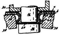
제4도는 제3도의 4-4선에 따른 단면도.4 is a cross-sectional view taken along line 4-4 of FIG.
제5도는 제3도의 5-5선에 따른 단면도.5 is a cross-sectional view taken along line 5-5 of FIG.
제6도는 제1-5도에 도시된 장치의 다이몸체의 사시도.6 is a perspective view of the die body of the apparatus shown in FIGS. 1-5.
제7도는 성형 완료 시점에서의 방수이음매를 나타내는 확대부분 단면도.7 is an enlarged partial cross-sectional view showing a waterproof joint at the time of completion of molding.
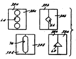
제8도는 본 발명에 따라 여러가지 형태의 이음매를 성형하는 다이들을 나타내는 도면.8 shows dies for forming various types of seams in accordance with the present invention.
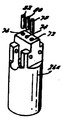
제9도는 제1-8도에 도시된 장치에 쓰이는 예시적인 다른 형태의 다이몸체의 부분 분해 사시도.9 is a partially exploded perspective view of another exemplary die body for use with the apparatus shown in FIGS. 1-8.
제10도는 제9도의 다이조립체와 함께 사용되기에 적합한 만능 펀치조립체의 부분 정면도.FIG. 10 is a partial front view of a universal punch assembly suitable for use with the die assembly of FIG.
제11도는 통상의 "절개형"이음매 형성에 적용될 수 있는 본 발명의 장치의 다른 실시예의 부분 정면도.11 is a partial front view of another embodiment of an apparatus of the present invention that can be applied to conventional "cutaway" seam formation.
제12도는 제11도의 장치의 측면도.12 is a side view of the apparatus of FIG.
제13도는 제11도 및 제12도의 장치에 의해 형성된 "절개형"이음매의 확대부분 단면도.FIG. 13 is an enlarged fragmentary sectional view of a “cutaway” seam formed by the apparatus of FIGS. 11 and 12.
제14도는 제13도의 14-14선에 따른 단면도.14 is a cross-sectional view taken along line 14-14 of FIG.
제15도는 방수이음매의 형성에 적용될 수 있는 이 발명에 의한 장치의 다른 실시예의 부분 사시도.15 is a partial perspective view of another embodiment of the device according to the present invention that can be applied to the formation of a waterproof joint.
제16도는 제15도의 장치의 부분 수직 단면도.FIG. 16 is a partial vertical section of the device of FIG. 15. FIG.
제17도는 방수이음매의 형성 완료 시점에 있는 제15도 및 제16도의 장치의 부분 단면도.FIG. 17 is a partial cross-sectional view of the device of FIGS. 15 and 16 at the time of completion of formation of the waterproof joint.
제18a도는 통상의 "절개형"이음매 형성에 적용될 수 있는 이 발명에 의한 장치의 다른 실시예의 부분 사시도.FIG. 18A is a partial perspective view of another embodiment of an apparatus according to the present invention that can be applied to conventional "cutaway" seam formation. FIG.
제18b도는 제18a도의 장치에서 비전단 다이부분들이 장치의 단부에 부가되어 있는 변형예를 나타내는 부분 사시도.FIG. 18B is a partial perspective view of a variant in which non-end die portions are added to the end of the device in the device of FIG. 18A;
제19도는 제18a도의 19-19선에 따른 단면도.19 is a cross-sectional view taken along the 19-19 line in FIG. 18A.
제20도는 방수이음매 형성에 적합한 이 발명의 장치의 또 다른 실시예의 평면도.20 is a plan view of another embodiment of the device of the present invention suitable for forming a seam.
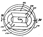
제21도는 제20도의 21-21선에 따른 단면도.FIG. 21 is a cross-sectional view taken along the 21-21 line in FIG. 20. FIG.
제22도는 제20도 및 제21도에 보인 실시예의 변형예를 나타내는, 제21도와 유사한 단면도.FIG. 22 is a sectional view similar to FIG. 21 showing a modification of the embodiment shown in FIGS. 20 and 21. FIG.
제23도는 통상의 "절개형" 이음매 형성에 적합한 이 발명의 장치의 또 다른 실시예의 평면도.Figure 23 is a plan view of another embodiment of an apparatus of the present invention suitable for forming conventional "cutaway" seams.
제24도는 제23도의 24-24선에 따른 단면도.24 is a cross-sectional view taken along the 24-24 line in FIG.
제25도는 제23도의 25-25선에 따른 단면도.25 is a cross sectional view along line 25-25 of FIG.
제26도는 이음매 형성 장치에 쓰이는 다수의 다이부분들을 거의 동시에 조립하기 위한 방법을 도식적으로 예시하는 4개의 바아재료의 단부도.FIG. 26 is an end view of four bar materials schematically illustrating a method for assembling a plurality of die portions used in a seam forming apparatus at about the same time.
제27도는 이 발명의 다른 실시예를 예시하는, 제20도와 유사한 평면도.FIG. 27 is a top view similar to FIG. 20 illustrating another embodiment of this invention.
제28도는 제27도의 28-28선에 따른 단면도.FIG. 28 is a cross sectional view along line 28-28 of FIG. 27;
제29도는 이 발명의 다른 실시예를 예시하는, 제23도와 유사한 평면도.FIG. 29 is a top view similar to FIG. 23 illustrating another embodiment of this invention.
제30도는 제29도의 30-30선에 따른 단면도이다.30 is a cross-sectional view taken along the 30-30 line of FIG.
* 도면의 주요부분에 대한 부호의 설명* Explanation of symbols for main parts of the drawings
10, 10a, 110, 210, 210A, 310, 310A, 410, 510 : 다이조립체10, 10a, 110, 210, 210A, 310, 310A, 410, 510: die assembly
16, 16a, 116, 216, 416 : 펀치 26, 26a, 126, 326 : 다이몸체16, 16a, 116, 216, 416: Punch 26, 26a, 126, 326: Die body
30, 130, 330 : 보스 36, 136, 236, 236A : 앤빌30, 130, 330: Boss 36, 136, 236, 236A: Anvil
38, 138, 238, 239A, 338, 438, 439, 538, 639 : 다이부분38, 138, 238, 239A, 338, 438, 439, 538, 639
94, 294, 294A : 절단날 145, 156 : 요홈부94, 294, 294A: Cutting blades 145, 156: Grooves
146, 246, 346, 446, 546, 646 : 탄성중합체 띠146, 246, 346, 446, 546, 646: elastomeric strip
180 : 바아재료 1847 : 절삭공구180 bar material 1847 cutting tool
370, 570, 670 : 슬리이브 372 : 제한 링370, 570, 670: sleeve 372: limit ring
571 : 홈571: home
이 발명은 판금이나 다른 판재를 접합하는 장치에 관한 것이다.The present invention relates to an apparatus for joining sheet metal or other sheet materials.
종래에는 다수의 판금 부분들을 펀칭하거나 다른 방식으로 조작하여 그 부분들이 특정 부위에서 서로 맞물리게끔 변형되게 함으로써 그 판금 부분들을 접합하였다. 그러나, 그러한 접합은 전형적으로 판재를 전단하는 것을 요하기 때문에, 밀봉재가 사용되지 않는 한 방수가 필요한 곳에는 적합하지 않았다. 종종 그러한 이음매의 형성은 피복 된 물질의 내부식성에 해를 끼친다. 더욱이, 이음매를 형성하는 종래의 장치는 구조가 상당히 복잡하여 펀치와 하나 또는 그 이상의 다이부분 모두를 작동하는데 큰 힘이 요구되며, 값이 비싼 미끄럼 다이부분을 필요로 한다. 이와 같은 복잡성은 작동에 필요한 에너지뿐만 아니라 장치의 가격을 증가시키다.Conventionally, the sheet metal parts are joined by punching or otherwise manipulating a plurality of sheet metal parts to deform the parts to engage each other at a particular site. However, such a bond typically requires shearing the plate, which is not suitable where waterproofing is required unless a sealant is used. Often the formation of such a seam harms the corrosion resistance of the coated material. Moreover, conventional devices for forming seams are quite complex in structure, requiring great force to operate both the punch and one or more die portions, and require expensive sliding die portions. This complexity increases the price of the device as well as the energy required for operation.
이 발명은 상기한 바와 같은 문제점을 감안하여 된 것으로서, 이 발명의 1차적인 목적은 판금이나 다른 판재를 영구적으로 접합하는 장치로서, 방수이음매나 통상의 "절개형"이음매를 형성할 수 있는 개량된 판재 이음 장치를 제공하는데 있다.The present invention has been made in view of the above-described problems, and a primary object of the present invention is an apparatus for permanently joining sheet metal or another sheet, and an improvement capable of forming a waterproof joint or a conventional cut-off joint. It is to provide a plate joining device.
이 발명의 다른 목적은, 구조가 비교적 간단하지만 내구성이 있고, 표준 펀치나 특수 펀치를 이용할 수 있으며, 매우 적은 힘을 요하고, 소형이기 때문에 여러 가지로 적용될 수 있으며, 접합되는 피복된 판재의 내부식성을 거의 보존하며, 소형 프레스의 부분으로 사용되거나 또는 대형 프레스의 C-프레임 호울더에 사용되기에 적합한 성형장치를 제공하는데 있다.Another object of this invention is that the structure is relatively simple but durable, can use standard punches or special punches, requires very little force and can be applied in various ways because of its small size, and it can It is to provide a molding apparatus that preserves almost corrosiveness and is suitable for use as part of small presses or for use in C-frame holders of large presses.
이 발명의 또 다른 목적은, 신규한 방수이음매 뿐만 아니라 통상의 "절개형"이음매를 포함하여 여러 가지 형상의 이음매를 형성하는데 적합하고, 판재 이음장치에 사용되는 개량된 다이조립체를 제공하는데 있다.It is yet another object of the present invention to provide an improved die assembly suitable for forming seams of various shapes, including conventional seamed seams as well as novel seam seams.
첨부된 도면들을 참조하여 이 발명의 실시예에 대하여 상세한 설명하면 다음과 같다.Hereinafter, exemplary embodiments of the present invention will be described in detail with reference to the accompanying drawings.
제1도 내지 제26도는 이 발명의 여러가지실시예 들을 예시한다. 제1-6도에, 2개의 판재(a,b) 또는 다른 성형 가능한 판재를 접합하기 위해 다이조립체(10)와 펀치조립체(12)로 구성된 판재이음장치가 도시되어 있다. 비록 2개의 판재만이 도시되어 있지만, 판재의 조성 및 두께에 따라서 2개 이상의 판재들이 이 발명에 따라 접합될 수 있음을 알아야 한다. 이 방법에 의해 접합될 가장 일반적인 판재로는, 알루미늄, 아연도금판, 청동, 강철 등의 피복된 판재와 피복되지 않은 그러한 판재가 있다. 이 발명의 장치는 용접될 수 없는 서로 다른 재료로 이루어진 판재를 잇는데 특히 유용하다.1 to 26 illustrate various embodiments of this invention. In FIGS. 1-6, a plate joint is shown, which consists of a
펀치조립체(12)는 통상의 구조로 되어 있으며, 원형 펀치(16)가 장착되어 있고 스트립퍼(stripper)보유기(20)를 나사식으로 지지하기 위한 나사부(18)를 가지고 있는 펀치몸체(14)를 포함한다. 스트립퍼보유기(20)내에 배치된 스트립퍼(2)는 코일스프링(24)에 의해서 제1도에 도시된 스트립핑 위치로 밀려있다. 제7도에 보인 바와 같이, 바람직하게는 펀치몸체(14)의 선단은 평탄하며, 그의 가장자리에서 반경이 작게 되어 있다.The punch assembly 12 is of a conventional construction and includes a circular punch 16 and a
다이조립체(10)는 지지구조물(28)내에 통상의 방식으로 장착된 원통형의 다이몸체(26)를 포함하는데, 이 지지구조물(28)은 표준 프레스에 사용되는 통상의 "C-프레임" 클램핑 장치의 하부다리(leg)이거나 또는 미합중국 특허 제3,730,044호에 개시된 바와 같은 소형 프레스의 하부다이지지 부분일 수 있다. 다이몸체(26)의 상단부(도시된 바와 같은)에는 제5도 및 제6도에 도시된 보스(boss)(30)가 일체로 설치되어 있는데, 이 보스(30)의 양측으로부터 4개의 어깨부(쇼울더)(32)가 뻗어 있다. 다이몸체 (26)의 중앙에는 보어(bore)가 들려 있으며, 다이몸체(26)의 상단부의 보어 부분(34) (제1도)내에는 경화된 핀으로 이루어진 앤빌(36)(제2도), 즉, 하부다이부재가 압입 끼워맞춤으로 배치되어 있다.The
다이몸체(26)의 각 측부에는, 다이부분(38)이, 구멍(42)내에 위치된 로울핀 (40) 또는 다른 피봇 부재에 의하여 피복 할 수 있게 지지되어 있다. 각각의 다이부분 (38)은 그 측면이 대략 T자형으로 되어 있으며, 그 다이부분(38)에는 다이몸체(26)의 2개의 어깨부(32)에 걸리는 2개의 어깨부(44)가 설치되어 있기 때문에 다이부분(38)에 수직으로 가해진 힘이 다이몸체(26)에 직접 전달되며 로울핀(40)에 의해 흡수되지 않는다.On each side of the die body 26, the die portion 38 is supported such that it can be covered by a roller pin 40 or other pivot member located in the hole 42. Each die portion 38 has a substantially T-shape at its side, and the die portion 38 is provided with two shoulder portions 44 caught by the two shoulder portions 32 of the die body 26. Because of this, the force applied perpendicular to the die portion 38 is transmitted directly to the die body 26 and is not absorbed by the roller pin 40.
다이 블록(38)들은, 제1도 및 제2도에 각각 도시된 위치들 사이에서 용이하게 제한적인 회전 운동, 즉, 피봇운동을 할 수 있도록 경사면(45)(제4도)을 가지고 있으며, 제1도에 보인 바와 같이 평상시 코일스피링(46)에 의해 폐쇄된 위치에 유지되어 있다. 코일스프링(46)은 보스(30)를 관통하여 뻗는 적당한 구멍(50)을 통과하고, 다이부분(38)에 하방으로 뻗는 일체의 다리(48)들 사이에서 작용한다(제4도 참조).The die blocks 38 have an inclined surface 45 (FIG. 4) to facilitate a limited rotational movement, ie pivoting, between the positions shown in FIGS. 1 and 2, respectively, As shown in FIG. 1, it is normally held in the closed position by the coil spring 46. As shown in FIG. The coil spring 46 passes through a suitable hole 50 extending through the
다이부분(38)들이 제1도에 도시된 폐쇄위치에 있을 때, 그들의 상부면(52)은 공통 수평면에 놓이고, 다이부분들의 서로 접하는 면들은 공통의 수직면(54)[혹은, 2개 이상의 다이부분들이 사용되는 경우에는 수직면들(54)]에 놓인다. 이 실시예에서 각각의 다이부분(38)에는 수직면(54)에 중심을 둔 상보적인 반원형 요홈부(56)가 있으며, 그 반원형 요홈부들은 다이부분들이 폐쇄 위치에 있을 때 펀치(16)와 일치하는 형상을 지닌 구멍을 이룬다.When the die portions 38 are in the closed position shown in FIG. 1, their upper surfaces 52 lie in a common horizontal plane, and the facing surfaces of the die portions are in common vertical plane 54 (or two or more). Die portions are used in the vertical planes 54. In this embodiment each die portion 38 has a complementary semi-circular groove 56 centered on the vertical surface 54, which coincides with the punch 16 when the die portions are in the closed position. Make a hole with a shape to make.
가공물에 작용하는 펀치(16)에 의해 다이부분(38)에 하방으로 가해지는 힘은 다이부분(38)들을 서로로 부터 먼쪽으로 선회시키지 않는데, 그 이유는 로울핀(40)에 의해 이루어진 피봇 축선이 요홈부(56)로 이루어진 구멍의 가장자리의 측방 외측으로 배치되어 있기 때문이다. 따라서, 펀치가 처음에 다이 구멍 안으로 들어간 때와 같이 펀치에 의해 다이부분에 가해진 어떠한 하방력도 다이조립체를 개방 시키기 보다는 폐쇄시키는 경향이 있다. 이 실시 예에서, 요홈부(56)로 이루어진 구멍의 가장자리는 제1도 및 7도에 번호(58)로 나타낸 바와 같이 둥그렇게 되거나 모따기가 되어서 판재 가공물을 부수거나 전단하는 기회를 감소시킨다.The force exerted downward on the die portion 38 by the punch 16 acting on the workpiece does not pivot the die portions 38 away from each other, because of the pivot axis created by the roller pin 40. It is because it is arrange | positioned outward the side of the edge of the hole which consists of this recessed part 56. Thus, any downward force exerted on the die portion by the punch, such as when the punch first enters the die hole, tends to close rather than open the die assembly. In this embodiment, the edges of the holes consisting of the recesses 56 are rounded or chamfered as indicated by numeral 58 in FIGS. 1 and 7 to reduce the chance of breaking or shearing the sheet workpiece.
작동에 있어서, 처음에 장치가 제1도에 도시된 위치에 있다 .먼저, 2개 또는 그 이상의 판재가 서로 면대 면으로 겹쳐 위치된 후, 제1도에 보인 바와 같이 장치 안에 놓이며, 이 때 판재 조립체의 하부면이 다이부분(38)의 표면(52)상에 배치된다. 그후, 프레스나 다른 장치가 작동되어 펀치가 판재들(a)(b)과 다이조립체(10)를 향하여 하방으로 이동되게 한다.In operation, the device is initially in the position shown in FIG. 1. First, two or more plates are placed superimposed on each other face to face, and then placed in the device as shown in FIG. The bottom surface of the plate assembly is disposed on the surface 52 of the die portion 38. Thereafter, a press or other device is actuated to cause the punch to move downwards towards the plates (a) (b) and the
펀치(16)와 판재가 접촉한 때 판재(a)(b)의 부분들(60)이 변형되어서 앤빌 (36)의 상부면을 향하여 하방으로 늘어난다. 요홈부(56)로 이루어진 구멍의 원주 둘레에 둥근부분(58)이 마련되어 있고 다이부분(38)과 펀치(16)사이의 간격이 바람직하게 균일하기 때문에 판재가 부서지거나 전단되지 않는다.When the punch 16 is in contact with the plate, the portions 60 of the plate (a) (b) are deformed and extend downwards towards the top surface of the anvil 36. Since the rounded portion 58 is provided around the circumference of the hole made of the recessed portion 56 and the spacing between the die portion 38 and the punch 16 is preferably uniform, the plate is not broken or sheared.
펀치와, 다이부분(38)의 요홈부(56)로 이루어진 구멍과의 상호작용에 의해 인발 작용이 곧바로 일어난다.The drawing action takes place immediately by the interaction between the punch and the hole formed in the recess 56 of the die portion 38.
펀치(16)가 다이 구멍내의 앤빌(36)에 다가가서 판재(a)(b)의 원래의 총 두께보다 작은 거리에 도달한 때 판재부분들(60)이 측방으로 압출되어 이 제7도에 보인 측방으로 확대된 형상(62)을 이루며, 그 결과, 판재들(a)(b)이 기계적으로 상호 접합된다. 이 점에 있어서, 제7도는 이음매를 형성하는 판재부분들의 단면 형상을 예시하기 위해 과장하여 도시되어 있다.When the punch 16 approaches the anvil 36 in the die hole and reaches a distance that is less than the original total thickness of the plates a and b, the plate portions 60 are laterally extruded to The laterally enlarged shape 62 is shown, with the result that the plates a, b are mechanically joined together. In this respect, FIG. 7 is exaggerated to illustrate the cross-sectional shape of the plate parts forming the seam.
판재부분(60)의 측방향 압출력으로 인하여 다이부분(38)들이 제2도 및 제7도에 도시된 바와 같이 측방 외측으로 피봇하게 된다. 강하고 영구적인 방수임매가 형성된 후 펀치는 제1도에 도시된 위치로 철회되며, 가공물이 제거된다. 여기에 예시된 장치에서는 오직 펀치(16)만이 작동하며, 앤빌(36)은 고정된채 유지되어 있으나, 다른 예에서는, 펀치를 정지시키고 다이조립체가 작동하게 할 수 있으며, 또는 펀치와 다이조립체 사이의 상대적인 운동을 제공하는 설비가 이용될 수도 있다. 가공물을 제거했을 때 코일스프링(46)은 다이부분(38)을 제1도에 도시된 폐쇄위치로 되돌아가게끔 피봇운동시킨다.The lateral extrusion force of the plate portion 60 causes the die portions 38 to pivot laterally outward as shown in FIGS. 2 and 7. After a strong, permanent waterproofing pad is formed, the punch is withdrawn to the position shown in FIG. 1 and the workpiece is removed. In the device illustrated here only the punch 16 works and the anvil 36 remains fixed, but in other instances, the punch can be stopped and the die assembly operated, or between the punch and the die assembly. A facility may be used that provides a relative movement of. When the workpiece is removed, the coil spring 46 pivots the die portion 38 back to the closed position shown in FIG.
상기한 바와 같은 장치에 있어서, 둥근 부분(58)을 제공하고 요홈부(56)로 이루어진 구멍과 펀치(16) 사이에 적당한 간격을 제공함으로써 판재부분의 전단이나 절개가 방지될 수 있다. 상기 간격은 일정한 폭으로 되는 것이 바람직하다. 부품들의 각 치수를 충분하게 최적화하지는 않았지만, 다음의 공식으로 만족할만한 치수를 설정할 수 있다.In the apparatus as described above, by providing a rounded portion 58 and by providing a suitable gap between the hole 16 consisting of the recessed portion 56 and the punch 16, shearing or cutting of the sheet portion can be prevented. It is preferable that the said space | interval becomes a fixed width. Although the individual dimensions of the components have not been sufficiently optimized, the following formula can set satisfactory dimensions.
P=2(M1+M2)(±20%)P = 2 (M1 + M2) (± 20%)
D=P+0.8(M1+M2)D = P + 0.8 (M1 + M2)
T=0.2[1.2(MQ+M2)]T = 0.2 [1.2 (MQ + M2)]
단, P=펀치직경P = punch diameter
D=다이직경D = die diameter
M1=상부판재두께M1 = upper plate thickness
M2=하부판재두께M2 = bottom plate thickness
T=이음매 중심에서의 총 판재 두께T = total plate thickness at seam center
이 공식은 최소한 처음에는 만족할만하다. 일단 펀치 직경을 선정하여 장치가 조립된 후 시험되면, 종래의 소형 프레스와 C-프레임상의 표준 "폐쇄높이" 조정부(도시되지 않음)를 이용하여 하부 앤빌 높이를 조정함으로써 프레스의 하향 행정이 끝난 때의 펀치 바닥과 앤빌 사이의 거리를 조정하면 만족스러운 결과가 얻어질 수 있다.This formula is at least satisfactory at first. Once the device has been assembled and tested with a punch diameter, the downstroke of the press is completed by adjusting the lower anvil height using a conventional compact press and standard “close height” adjustment (not shown) on the C-frame. Satisfactory results can be obtained by adjusting the distance between the punch bottom and the anvil.
비록 제1-7도의 실시예에서 원형펀치가 사용되고 있지만, 적용분야와 요구되는 강도에 따라서 다른 형태의 펀치를 사용할 수도 있다. 예를 들어 제8도는 서로 다른 4가지의 사용 가능한 형상의 예들을 나타낸다. 다이부분(38a)에는, 소망의 회전방지 특성이나 강도 특성 때문에 1개 이상의 원형 이음매를 필요로 하는 경우를 위하여 3개의 원형구멍(64)이 설치되어 있다.Although circular punches are used in the embodiments of FIGS. 1-7, other types of punches may be used depending on the application and the strength required. For example, FIG. 8 shows four different examples of usable shapes. The die portion 38a is provided with three circular holes 64 for the case where one or more circular seams are required because of the desired anti-rotation characteristics or strength characteristics.
다이부분(38b)에는, 제1실시예와 대등한 강도를 지닌 이음매를 제공하면서도 회전방지 특성을 더 좋게 하는 다이아몬드형 구멍(66)이 있다. 다이부분(38c)에는, 다이아몬드형 구멍(66)이 유사한 결과를 제공하는 삼각형 구멍(68)이 있다. 다이부분 (38d)에는, 높은 강도와 회전방지 특성을 지닌 비교적 큰 이음매를 제공하는 타원형구멍(70)이 있다. 단면형상에 관계없이 판재의 상부부분의 인발된 부분은 내측벽은 전형적으로 대략 원통 형상이다.In the die portion 38b, there is a diamond-shaped hole 66 which provides a seam with a strength comparable to that of the first embodiment while still providing better anti-rotation characteristics. In die portion 38c there is a triangular hole 68 in which the diamond-shaped hole 66 provides a similar result. In the die portion 38d there is an
제9도는 만능형 다이몸체(26a)를 나타내며, 이 다이몸체는 제1실시예의 다이몸체(26)와 거의 동일하지만, 그러나 압입 끼워맞춤 상태로 단단한 앤빌핀들 (78) (80)(82)을 각기 수용하기에 적합하게 된 다수의 구멍들(72)(74)(76)이 수직으로 나란히 정렬되어 설치되어 있다. 하나의 원형 이음매로써 충분한 경우에는, 다이몸체 (26a)에서 2개의 앤빌핀들(78)(82)을 제거하여 장치에 필요한 에너지를 감소시킨다.9 shows a universal die body 26a, which is substantially the same as the die body 26 of the first embodiment, but with rigid fit anvil pins 78, 80, 82 in press fit. A plurality of
한편, 더 큰 강도나 회전방지 특성이 필요한 경우에는 1개 또는 2개 이상의 부가적인 핀을 적당한 구멍에 삽입함으로써 이음성능을 더 부여할 수 있다. 다이몸체(26a)에 고착된 다이부분의 상부 형상은 제8도에 도시된 다이부분(38a)의 형상과 유사하며, 구멍(64)이 앤빌핀들(78)(80)(82)과 협동하도록 설계되어 있다.On the other hand, if greater strength or anti-rotation characteristics are required, the joint performance can be further imparted by inserting one or two or more additional pins into suitable holes. The upper shape of the die portion fixed to the die body 26a is similar to the shape of the die portion 38a shown in FIG. 8, so that the holes 64 cooperate with the anvil pins 78, 80 and 82. It is designed.
제10도는 제9도의 만능 다이몸체와 함께 사용될 수 있는 펀치의 하부 부분이 도시되어 있다. 펀치몸체(84)는 모든 면에서 종래와 동일할 수 있으며, 제1-7도의 실시 예에서 펀치(16)가 앤빌(36)과 협동하는 것과 동일한 방식으로 각각의 앤빌핀들 (78)(80)(82)과 협동하기에 적합하게 되고 압입 끼워맞춤된 다수의 경화된 강철펀치핀들(86)(88)(90)을 구비하고 있다. 특정한 적용예에 따라 펀치를 바꾸거나 핀치 갯수를 줄일 수 있게끔 펀치를 제거할 수 있도록 펀치몸체(84)에 적당한 구멍(92)들이 마련되어 있다. 또 다르게는, 펀치 핀과 앤빌핀의 단면 형상은 특정한 적용예에 따라서 원형이 아닐 수도 있다.FIG. 10 shows a lower portion of the punch that can be used with the universal die body of FIG. The punch body 84 may be the same as conventional in all respects, and the respective anvil pins 78 and 80 in the same manner as the punch 16 cooperates with the anvil 36 in the embodiment of FIGS. 1-7. It is equipped with a number of hardened steel punch pins 86, 88, 90 that are adapted to cooperate with 82 and press fit. Depending on the particular application, suitable holes 92 are provided in the punch body 84 to remove the punches so as to change the punch or reduce the number of pinches. Alternatively, the cross-sectional shape of the punch pin and anvil pin may not be circular depending on the particular application.
제11도 및 제12도에서, 제13도 및 제14도에 도시된 바와 같은 통상의 "절개형" 이음매를 형성할 수 있도록 약간 개조된 다이조립체(10a)와 펀치(16a)가 도시되어 있다.In FIGS. 11 and 12, a die assembly 10a and punch 16a are shown that are slightly adapted to form conventional “cutaway” seams as shown in FIGS. 13 and 14. .
이 실시예의 다이조립체(10a)는 다이몸체(26b)를 포함하며 제1실시예의 다이조립체(10)와 거의 동일하지만(제1-12도의 실시 예들에서 동일하거나 유사한 부분에는 동일하거나 유사한 참조 번호가 사용됨), 다이부분(38e)에 펀치 수용 구멍을 형성하는 요홈부가 설치되어 있지 않으며, 그 대신 절단날(94)들이 설치되어 있는 점이 다르다. 또한, 앤빌은, 절단날(94)의 거의 전 길이에 걸쳐 뻗으며 연속적으로 평탄하게 일체로 형성된 거의 수평인 표면(96)을 포함한다. 이 실시예의 펀치(16a)는 대개 삽 형태이며, 그의 폭이 절단날(94)들 사이의 간격과 거의 동일하며, 모따기된 모서리(98)를 가진다.The die assembly 10a of this embodiment includes a die body 26b and is substantially the same as the
제13도 및 제14도에서, 금속 판재(c)(d)가 제113도 및 제12도의 장치에 의해 접합된 것으로 도시되어 있다. 펀치(16a)가 다이조립체를 향하여 하방으로 이동함에 따라서, 판재부분(100)(102)은 각기 판재모재(c)(d)에서 절개되어 나온다. 이러한 판재부분(100)(102)은 제13도에 잘 도시된 바와 같이 양끝에서 판금모재에 일체로 부착되어 있지만, 제14도에 보인 바와 같이 측면(104)을 따라서는 판금모재(c)(d)로 부터 전체적으로 절단된다.In FIGS. 13 and 14, the metal sheet (c) (d) is shown as joined by the apparatus of FIGS. 113 and 12. As the punch 16a moves downward toward the die assembly, the
펀치가 앤빌을 향하여 계속 전진하면 판재부분(100)(102)이 측방으로 압출되어 제14도에 도시된 확대부분이 생성되며, 이 확대부분은 이음의 일체성을 제공하는데 필요한 기계적인 상호결합을 제공한다. 그러나, 판재가 절개되기 때문에, 그러한 형태의 이음매는 방수가 안된다. 판재부분이 측방으로 압출됨에 따라 다이부분들(38e)이 서로 멀어지게 피봇되어 측방으로의 압출을 용이하게 한다. 이와 같은 다이조립체를 사용하면, 가동 앤빌과 복잡한 미끄럼 다이를 이용하지 않고서도 그러한 형식의 이음매를 매우 만족스럽게 형성할 수 있는 것이다.As the punch continues to advance towards the anvil, the
제15-17도는 방수이음매 식으로 판재를 서로 접합하는 장치의 다른 실시예를 나타낸다. 이 실시예에서, 방수이음매를 형성하도록 펀치(116)와 협동하기에 적합하게된 다이조립체(110)는, 보스(130)를 일체로 가지며 그위에 환형어깨부(132)가 다이몸체(126)를 포함한다. 보스(130)는 앤빌(136)과 환형어깨부(132)를 상호 연결하는 원추부분(131)을 포함한다.15-17 show another embodiment of a device for joining sheets together in a waterproof seam manner. In this embodiment, the
2개 또는 그 이상의 궁형의 다이부분(138)이 보스(130)의 둘레에 배치되고, 다이몸체(126)의 환형어깨부(132)에 걸리어 지지되는 어깨부(144)를 가지고 있다. 보스(130)에는 환형어깨부(132)에 인접한 환형요홈부(145)가 형성되어 있다. 이 환형어깨부(145)는, 제1-10도의 실시예와 관련하여 기술된 다이부분(38)과 동일한 방식으로 이음매가 완성됨에 따라 다이부분(138)이 횡방향 축선을 중심으로 하여 주로 외측으로 피봇할 수 있도록 간격을 제공한다.Two or more arched die portions 138 are disposed around the boss 130 and have a shoulder portion 144 that is supported by the
다이부분(138)은 평상시 탄력성의 탄성중합체 띠(146)에 의해 제15도 및 제16도에 보인 폐쇄 위치에 유지되는데, 이 띠는 다이부분(138)을 다이조립체의 종축선쪽을 향하여 측방 내측으로 탄성적으로 밀도록 다이부분(138)의 측면을 둘러싼다. 탄성 띠(146)는 다이부분(138)의 원주방향으로 뻗는 측방 내측으로 패인 홈(150)안에 수용되어 길이 방향으로 움직이지 못하게 구속되어 있다. 비록 탄성 띠(146)가 이 발명의 특정 적용 예에 적합한 각종 탄성중합체 재료들 중 어느 하나로 이루어질 수 있지만, 우레탄이나 함유 재료로 이루어지는 것이 바람직하다.The die portion 138 is held in the closed position as shown in FIGS. 15 and 16 by the normally elastic elastomeric strip 146, which laterally inwards the die portion 138 toward the longitudinal axis of the die assembly. It surrounds the side of the die portion 138 to push elastically. The elastic strip 146 is accommodated in the
다이부분(138)이 제15도 및 제16도에 도시된 폐쇄 위치에 있을 때, 상부 표면(152)들은 공통의 평면에 놓이고, 인접한 다이부분들의 서로 접하고 있는 면들은 평면(154)에 놓인다. 제15도 및 제16도에 보인 실시 예에서, 다이부분(138)에는 펀치(116)의 가로방향 단면형상과 대략 일치하는 원형구멍을 이루는 원형의 요홈부 (156)들이 형성되어 있다. 다이부분(138)은 또한, 둥그런 가장자리부분(158)을 가지고 있으며, 판재의 변형중 판재(a)(b)를 전단하거나 찢는 일을 피하기 위하여 펀치 (116)로 부터 일정하게 떨어져 있는 것이 바람직하다. 제1-10도에 보인 실시예와 같이, 펀치(116)에 의해 다이부분(138)에 가해진 하향력은 최소한 처음에 다이조립체 (110)를 개방시키기 보다는 폐쇄시키는 경향이 있다. 왜냐하면 다이부분의 어깨부(144)와 다이몸체의 환형어깨부(132)가 가장자리부분(158)에 대하여 측방 외측 위치에서 맞물려 길이방향으로 지지된채 주로 피봇운동하기 때문이다. 더욱이, 환형어깨부(132)는 장치의 작동시 다이부분(138)에 가해진 축선 방향 하중을 쉽게 감당할 수 있는 견고한 표면을 형성한다.When the die portion 138 is in the closed position shown in FIGS. 15 and 16, the
작동에 있어서, 다이조립체(110)는 상기 제1-10도의 다이조립체(110)와 유사하게 작동한다. 그러나, 탄성 띠(146)는 다이부분(138)을 원주방향으로 연속적으로 접하면서 안쪽으로 밀기 때문에 다이부분(138)이 좀더 균일하게 안쪽으로 밀리게 하므로써 판재부분(160)이 다이부분(138)에 이해 형성된 원형 구멍 안으로 더욱 균일하고 조절적으로 변형되게 한다. 제15-26도의 탄성 띠는 여러 가지 다이 요소들을 그들의 적절한 위치에 정렬되게 보유하는 동시에 분해를 용이하고 편리하게 한다. 또한, 각 부분들의 간격도 제1-10도의 실시 예에 사용된 것과 동일한 기준에 근거한 것이기 때문에 판재부분(160)은 터지거나 전단되지 않은 일정한 형상으로 요홈부(156)로 이루어진 구멍안으로 인발된다. 처음의 실시예에서와 같이, 앤빌(136)에 대한 펀치(116)의 작용은 판재를 측방으로 압출시켜서 제17도에 도시된 방식으로 방수이음매를 형성하는 것이다. 탄성 띠(156)는, 이음매의 균일하고 조절적인 성형에 기여할 뿐만 아니라, 다이조립체의 제작, 작동, 유지를 간단하고 저렴하게 한다.In operation, the
제15-17도에 보인 실시예에서는 원형펀치(116)가 이용되고 있지만, 특정 적용 예와 필요한 강도에 따라 다른 형상도 사용될 수 있다. 그러나 형상과, 그 형상을 형성하기 위하여 장치에 필요한 변형이 제8-10도에 도시되어 있고 앞에서 설명되었다. 또한, 도시된 실시예들에서 다이부분의 갯수는 단지 예시의 목적을 위한 것이며, 이 발명의 여러 가지 실시예는 2개, 또는 다른 합리적인 갯수의 다이부분을 가질 수 있다.Although the circular punch 116 is used in the embodiment shown in FIGS. 15-17, other shapes may be used depending on the particular application and the required strength. However, the shape and the modifications necessary for the device to form the shape are shown in FIGS. 8-10 and described above. In addition, the number of die portions in the illustrated embodiments is for illustrative purposes only, and various embodiments of the present invention may have two or other reasonable numbers of die portions.
제18 및 제19도는 제13도 및 제14도에 도시된 바와 같은 통상의 "절개형"이음매를 형성하는 펀치와 협동을 할 수 있는 다이조립체(110)의 변형예를 나타낸다. 이 변형예의 다이조립체(210)는, 펀치를 수용하는 원형구멍을 형성하는 반원형 요홈부 (156)가 다이부분(238)에 설치되어 있지 않다는 점에 있어서 제15-17도의 것과 다르다. 그 대신, 이 다이부분(238)에는 대략 삽 모양의 펀치(216)와 협동할 수 있는 똑바른 절단날(294)이 설치되어 있는데, 이 펀치(216)의 형상은 제11도 및 제12도에 보인 펀치(16a)와 거의 비슷하다.18 and 19 show a modification of the
거의 모든 점에 있어서, 제18a도 및 제19도의 실시예는 제11도 및 제12도에 보인 다이조립체(10a)와 비슷한 방식으로 작용하지만, 탄력성의 탄성중합체 띠(246)에 의해 내측으로 미는 작용의 균일함, 간단함, 및 경제성의 장점이 제공되며, 이 탄성 띠(246)의 조성과 기능은 제15-17도에 보인 탄성 띠(146)와 사실상 동일하다.In almost all respects, the embodiment of FIGS. 18A and 19 acts in a similar manner to the die assembly 10a shown in FIGS. 11 and 12, but is pushed inward by the elastic
제18a도는 제18도 및 제19도의 다이조립체(210)의 변형예를 나타내는데, 이 변형예의 다이조립체(210A)는 앤빌(236A)의 각 단부에 비전단 다이부분(239A)이 설치되어 있다. 그러한 다이부분(239A)은 모서리(258A)가 둥그렇게 되어 있는 것이 바람직하고, 펀치(216)로부터 충분히 이격되어 변형된 판재의 단부부분에서 판재가 전단되거나 찢어지는 일이 방지되게 한다.18A shows a modification of the die assembly 210 of FIGS. 18 and 19, wherein the die assembly 210A of this modification is provided with a non-end die portion 239A at each end of the anvil 236A. Such die portion 239A preferably has rounded corners 258A and is sufficiently spaced apart from punch 216 to prevent shearing or tearing of the sheet at the end portion of the deformed sheet.
따라서, 그러한 실시예에 있어서 절개형 이음매의 형성시 단부부분을 필요한 바대로 성형 및 지지할 수 있음과 동시에, 판재의 전달을 다이조립체(210) 또는 (210A)의 절단날(294) 또는 (294A)로 국한시킬 수 있는 것이다.Thus, in such an embodiment, the end portion can be shaped and supported as needed in the formation of the cutaway seam, while the transfer of sheet material is carried out at the cutting edges 294 or 294A of the die assembly 210 or 210A. It can be limited to).
제20-22도는 방수이음매를 형성하는 장치의 또 다른 실시예에 대한 변형 예들을 나타내는데, 제20도 및 제21도의 다이조립체(310)는, 대략, 원형인 구명을 형성하고 탄력성의 탄성중합체 띠(346)에 의해 내측으로 탄력적으로 밀리는 다이부분(338)을 포함한다.20-22 illustrate variants of another embodiment of a device for forming a waterproof seam, wherein the die assemblies 310 of FIGS. 20 and 21 form approximately circular, life-saving, elastic elastomeric strips. 346 includes a
제15-17도에 보인 이 발명의 약간 유사한 실시예와는 달리, 다이몸체(326)에는 보스(330)의 원추형부분(331)과 어깨부(332)사이에 요홈부가 없다. 그리하여, 활모양의 다이부분(338)은 처음에는 최소한 측방 외측으로 피봇하지 않으며, 대신에 그의 단부(334)에 평평한 단부 표면이 설치되어서 다이조립체(310)의 작동시 어깨부 (332)(이 실시 예에서는 넓혀져 있음)상에서 최소한 처음에는 주로 미끄러질 수 있다. 그러나, 이제까지 기술된 모든 실시예에서 처럼, 모든 다이부분들은 대략 동일한 정도로 피봇하거나 미끄러질 수 있게되어 있기 때문에 이음매가 가능한한 균일하게 되는 것이다.Unlike a slightly similar embodiment of this invention shown in FIGS. 15-17, the
다이조립체(310)는 탄력성의 탄성중합체 띠(346)를 길이 방향으로 못움직이게 위치시키는 플랜지(351)를 끝에 가지는 외측표면(350)이 다이부분(338)에 마련되어 있다는 점에 있어서 제15-17도의 다이조립체(110)와 다르다. 또한, 다이부분(338)이 측방 외측으로 심하게 이동하거나 너무 많이 사용됨으로 인하여 다이부분(338)이나 탄성 띠(346)에 가해질 수 있는 손상을 실질적으로 최소화하기 위하여 다이몸체(326)에는 슬리이브(370)가 나사 결합되어 있다.The die assembly 310 is provided with an
이 슬리이브(370)는 다이부분(338)과 탄성 띠(346)를 둘러싸서 그들의 측방 외측으로의 이동을 제한하고 그들을 보호한다. 이 발명의 여러 가지 다른 실시예에서 그들이 방수이음매를 형성하는데 적합하든 "절개형"이음매를 형성하는데 적합하든지, 그러한 실시에가 피봇운동하는 다이부분을 채용하든지 혹은 미끄럼 운동하는 다이부분을 하든지에 관계없이, 다이부분과 탄성 바이어스 수단에 가해질 수 있는 손상을 최소화하도록 슬리이브(370)가 유익하게 사용될 수 있다.This sleeve 370 surrounds the
제22도는 제20도 및 제21도의 실시예의 변형을 나타낸다. 이 다이조립체 (310A)는 제20도 및 제21도의 다이조립체(310)와 거의 유사하지만, 다이부분(338)을 측방에서 둘러싸고 탄성 띠(346)와 다이부분(338)의 플랜지(351)사이에서 바람직하게는 길이방향으로 붙잡혀 있는 제한 링(372)으로 슬리이브(370)를 대신한 점이 다르다. 그 제한링(372)은 대략 슬리이브(370)와 동일한 방식으로 작용한다.22 shows a variant of the embodiment of FIGS. 20 and 21. This die assembly 310A is almost similar to the die assembly 310 of FIGS. 20 and 21, but surrounds the
즉, 그 제한 링은 측방 외측으로 과도하게 피봇운동하거나 미끄러짐으로써 다이부분과 탄성 띠에 가해질지도 모르는 손상을 최소화하도록 다이부분의 측방 외측으로의 이동을 제한한다. 슬리이브(370)와 같이, 제한 링(372)이 다른 실시예에 사용될 수 있도록 개조될 수 있다. 즉, 그 링의 형상을 이음매가 원형이 아닌 경우에 대략 타원형이나 직사각형으로 적절히 수정될 수 있다.That is, the confinement rings restrict movement of the die portion laterally outward to minimize damage that may be exerted on the die portion and elastic band by excessively pivoting or sliding laterally outward. As with sleeve 370, the confinement ring 372 can be adapted to be used in other embodiments. That is, the shape of the ring can be appropriately modified to approximately oval or rectangular when the seam is not circular.
제23-25도는 다이조립체(410)를 나타내는데, 이 다이조립체(410)는 주로 미끄럼 운동할 수 있는 다이부분들(438)(439)이 설치되어 있다는 점에 있어서, 제20-22도의 다이조립체(310)(310A)와 비슷하다. 그러나, 삽 모양의 펀치(416)의 최소한 일부분과 형상이 대략 일치하는 대략 직사각형의 구멍을 이루기 위하여 한쌍의 비전단 다이부분(439)과, 전단날(494)을 가지고 측면이 똑바른 한쌍의 다이부분(438)이 설치되어서 상기한 방식으로 "절개형"이음매를 형성하기에 적합하게 되어 있다는 점에 있어서 다이조립체(410)는 또한 제18a도의 다이조립체(210A)와 어느정도 유사하다. 다이부분들(438)(439)은 전술한 탄성 띠들과 비슷한 탄력성의 탄성중합체 띠(446)에 의해 측방에서 둘러싸이고 내측으로 밀어붙여져 있다.Figures 23-25 show the die assembly 410, which is the die assembly of FIGS. 20-22, in that the
다이조립체(410)에는 둥그런 가장자리(458)를 가진 비전단 다이부분(439)이 장착되어 있음에 유의해야 한다. 제23-25도에 보인 다이조립체(410)의 실시예에 있어서, 다이부분(439)은 활모양이며, 바람직하기로는 제20-22도에 보인 실시예의 활모양의 다이부분(338)과 동일하여 서로 교체할 수 있다. 다이부분들의 그러한 상호 교체성은 이 발명에 의한 다이조립체의 제작 및 작동의 간단함 및 경제성에 크게 기여하는 것이다.Note that the die assembly 410 is equipped with a non-end die portion 439 having a rounded edge 458. In the embodiment of die assembly 410 shown in FIGS. 23-25, the die portion 439 is bowed, preferably the same as the bowed
제26도는 상기한 형태의 다수의 (이 경우에는 4개) 다이부분들을 거의 동시에 제조하기 위한 매우 간단한 방법을 도식적인 형태로 나타낸다. 다이부분들로 성형될 미리 선택된 재료로 이루어지고 치수가 적당한 4개의 정방형 바아(bar)재료(180)를 제26도에 보인 바와 같이 측면들이 서로 맞닿게끔 서로 묶어서 물린다. 그리고 나서, 적당한 절삭공구(184)를 사용하여 동시에 선삭하여 외측형상(186)을 성형하고, 그 다음에 통상의 방식으로 동시에 구멍을 뚫어서 예를 들어 다이부분(138)의 내측 원주형상(188)을 성형한다. 또 다르게는, 바아재료(180)의 부분들이 회전하지 못하게 정지된 상태에서 적당한 절삭공구가 이동하여 원하는 작업을 수행하기도 한다. 일단 내측 및 외측형상(188)(186)이 각기 성형된 후, 그 재료 부분들을 풀면 4개의 다이부분(138)이 만들어진다. 그러한 공정으로 인하여 다이부분이 균일하게 형성될 뿐만 아니라, 다이조립 절차가 쉽고, 빠르고, 경제적으로 된다.FIG. 26 shows, in schematic form, a very simple method for producing a plurality of (in this case four) die portions of the type described above at about the same time. Four square bar materials 180 of suitable and dimensioned material that are to be molded into die portions are tied together so that the sides touch each other as shown in FIG. Then, by turning simultaneously with the
제27-30도는 이 발명의 다른 실시 예들을 나타내는데, 제27도 및 제28도의 실시예는 제20도 및 제21도의 실시예와 어느 정도 비슷하다. 그러나, 탄력성의 탄성중합체 띠(546)가 다이부분(538)과 슬리이브(570)사이에서 다이조립체(510)상에 일체로 성형되고 제28도에 보인 바와 같이 다이부분(538)의 운동시 압축 가능하게 벌어진다. 슬리이브(570)내의 탄성 띠(546)의 부착 또는 보유를 증진시키기 위하여 슬리이브(570)내부에는 바람직하게는 다수의 홈(571)이 형성된다. 유사하게, 제29도 및 제30도는 제23-25도의 실시예에 대한 변형예를 나타내지만, 이 예에서는 탄력성의 탄성중합체 띠(646)가 제27도 및 제28도의 실시예와 비슷한 방식으로 다이부분들 (638)(639)과 슬리이브(670) 사이에 일체로 성형되어 있다.27-30 illustrate other embodiments of the invention, wherein the embodiments of FIGS. 27 and 28 are somewhat similar to the embodiments of FIGS. 20 and 21. However, an elastic elastomeric strip 546 is integrally formed on the die assembly 510 between the die portion 538 and the
그러한 탄력성의 탄성중합체 띠는 제15-30도에 보인 실시 예들에서도 상기한 바와 같이 일체로 성형되어 설치 될 수 있음에 유의해야 한다. 그처럼 일체로 성형된 띠를 설치함으로써 다이조립체가 단일화된 일체의 조립체로서 이음매 성형장치에 설치될 수 있다. 더욱이, 이 같은 구조로 인하여 제15-19도에 보인 요홈부(145)(245)가 제거되거나 적어도 최소화될 수 있는 것이다.It should be noted that such elastic elastomeric bands may be integrally molded and installed as described above in the embodiments shown in FIGS. By providing such an integrally formed strip, the die assembly can be installed in the seam forming apparatus as a unitary unitary assembly. Moreover, this structure allows the
Claims (18)
Applications Claiming Priority (2)
| Application Number | Priority Date | Filing Date | Title |
|---|---|---|---|
| US06/853,130 US4757609A (en) | 1980-09-08 | 1986-04-17 | Apparatus for joining sheet material |
| US853,130 | 1986-04-17 |
Publications (2)
| Publication Number | Publication Date |
|---|---|
| KR870009782A KR870009782A (en) | 1987-11-30 |
| KR910006547B1 true KR910006547B1 (en) | 1991-08-28 |
Family
ID=25315142
Family Applications (1)
| Application Number | Title | Priority Date | Filing Date |
|---|---|---|---|
| KR1019870000507A KR910006547B1 (en) | 1986-04-17 | 1987-01-22 | Apparatus for joining sheet material |
Country Status (7)
| Country | Link |
|---|---|
| US (1) | US4757609A (en) |
| JP (1) | JPH06104253B2 (en) |
| KR (1) | KR910006547B1 (en) |
| CA (1) | CA1311347C (en) |
| DE (1) | DE3713083C3 (en) |
| GB (1) | GB2189175B (en) |
| MX (1) | MX165750B (en) |
Families Citing this family (83)
| Publication number | Priority date | Publication date | Assignee | Title |
|---|---|---|---|---|
| US5027503A (en) * | 1980-09-08 | 1991-07-02 | Btm Corporation | Apparatus for joining sheet material |
| US5177861A (en) * | 1980-09-08 | 1993-01-12 | Btm Corporation | Apparatus for joining sheet material |
| US4910853A (en) * | 1980-09-08 | 1990-03-27 | Btm Corporation | Apparatus for joining sheet material |
| US5208974A (en) * | 1980-09-08 | 1993-05-11 | Btm Corporation | Apparatus for attaching a fastener to sheet material |
| US5208973A (en) * | 1980-09-08 | 1993-05-11 | Btm Corporation | Apparatus for joining sheet material |
| US5435049A (en) * | 1980-09-08 | 1995-07-25 | Btm Corporation | Apparatus for joining sheet material |
| US5131258A (en) * | 1985-06-03 | 1992-07-21 | Btm Corporation | Punch anvils for sheet fastening systems |
| US5031442A (en) * | 1985-06-03 | 1991-07-16 | Btm Corporation | Punch anvils for sheet fastening systems |
| US5207086A (en) * | 1985-06-03 | 1993-05-04 | Btm Corporation | Punch anvils for sheet fastening systems |
| DE3679364D1 (en) * | 1985-09-14 | 1991-06-27 | Eugen Rapp | METHOD AND DEVICE FOR CONNECTING THIN PLATES. |
| DE3710929A1 (en) * | 1987-04-01 | 1988-10-13 | Eugen Rapp | METHOD AND DEVICE FOR CONNECTING LAYER THIN PLATES |
| US4878284A (en) * | 1987-12-31 | 1989-11-07 | Btm Corporation | Hand held sheet metal joining system |
| JPH069709Y2 (en) * | 1988-01-05 | 1994-03-16 | 三洋機工株式会社 | Metal sheet bonding equipment |
| DE3805688A1 (en) * | 1988-02-24 | 1989-09-07 | Eckold Vorrichtung | DEVICE FOR IMPLEMENTING SHEET METAL PIECES |
| DE8803773U1 (en) * | 1988-03-19 | 1988-06-01 | Walter Eckold Gmbh & Co Kg Vorrichtungs- Und Geraetebau, 3424 St Andreasberg, De | |
| DE3836937A1 (en) * | 1988-10-29 | 1990-05-03 | Eckold Vorrichtung | ENFORCEMENT DEVICE |
| DE3923182A1 (en) * | 1989-07-13 | 1991-01-24 | Fraunhofer Ges Forschung | Joining metal sheets together - involves punch and undercut die to cause sheets to interlock |
| US5036577A (en) * | 1989-11-30 | 1991-08-06 | Thomson Consumer Electronics, Inc. | Method of forming a shrink fit implosion protection band |
| US5528815A (en) * | 1990-04-03 | 1996-06-25 | Webb; Edward L. T. | Clinching tool for sheet metal joining |
| NZ237649A (en) * | 1990-04-03 | 1993-10-26 | Edward Leslie Theodore Webb | Clinching apparatus with split collet die for joining overlapping sheets of material |
| US5055934A (en) * | 1990-06-05 | 1991-10-08 | Thomson Consumer Electronics, Inc. | Implosion protection means having mounting lug base-accommodating concavities therein |
| US5064394A (en) * | 1990-06-05 | 1991-11-12 | Thomson Consumer Electronics, Inc. | Method of forming a shrinkfit implosion protection band having a concavity therein |
| US5310158A (en) * | 1990-07-22 | 1994-05-10 | Bks Company | Hanger clamp assembly |
| US5211117A (en) * | 1991-09-11 | 1993-05-18 | Lorin Industries, Inc. | Pallet assembly |
| DE9114122U1 (en) * | 1991-11-13 | 1993-04-01 | Eckold Gmbh & Co Kg, 3424 St. Andreasberg, De | |
| US5259102A (en) * | 1992-04-13 | 1993-11-09 | Reo Hydraulic Pierce & Form, Inc. | Clinching tool |
| US5230136A (en) * | 1992-05-04 | 1993-07-27 | Savair Inc. | Punch and die set for sheet metal clinching |
| FR2691388B1 (en) * | 1992-05-21 | 1997-01-31 | Homax Ag | NEW ASSEMBLY POINT OF SHEET SHEETS BY COLD CREAM AND TOOL MACHINE FOR MAKING SUCH AN ASSEMBLY POINT. |
| FR2692181B1 (en) * | 1992-06-15 | 1994-09-02 | Homan Ag | New point of assembly of sheets by cold creep and tools for the realization of said point of assembly. |
| FR2693930B1 (en) * | 1992-07-24 | 1994-09-23 | Homax Ag | Improvements to tools for making sheet metal assembly points. |
| DE9210062U1 (en) * | 1992-07-27 | 1992-09-24 | Eckold Ag, Trimmis, Ch | |
| US5432989A (en) * | 1992-10-27 | 1995-07-18 | Archer Manufacturing Corporation | Apparatus and method for joining sheet material |
| DE4240970A1 (en) * | 1992-12-05 | 1994-06-09 | Eckold Vorrichtung | Process for joining sheet metal, sheet metal parts or plates lying flat on top of one another |
| CA2115896A1 (en) * | 1993-03-16 | 1994-09-17 | Edwin George Sawdon | Force generating mechanism |
| FR2704785B1 (en) * | 1993-05-04 | 1995-07-21 | Homax Ag | Improvements to tools for the realization of assembly points of sheets by cold creep. |
| EP0664170B1 (en) * | 1994-01-24 | 1998-09-09 | Homax Ag | Improvements on tools for making point connections of plates |
| US5727302A (en) * | 1994-01-31 | 1998-03-17 | Btm Corporation | Die and punch for forming a joint and method of making the die |
| US5479687A (en) * | 1994-01-31 | 1996-01-02 | Btm Corporation | Apparatus for joining sheets of material |
| DE4404659C5 (en) * | 1994-02-14 | 2009-10-22 | Böllhoff & Co. GmbH & Co. KG | Method for producing a riveted joint and tool for carrying out the method |
| US5984563A (en) * | 1994-07-22 | 1999-11-16 | Btm Corporation | Apparatus for joining sheet material and joint formed therein |
| US5860315A (en) * | 1994-07-29 | 1999-01-19 | Etm Corporation | Device for securing tools |
| DE4435460A1 (en) * | 1994-10-04 | 1996-04-11 | Boellhoff Gmbh Verbindungs Und | Process using stamp and anvil for fixing overlapping metal sheets |
| US5737819A (en) * | 1995-05-10 | 1998-04-14 | Btm Corporation | Fastening apparatus |
| SE9502587D0 (en) * | 1995-07-11 | 1995-07-11 | Attexor Equip | A tool for making joints between sheet-formed members |
| US6052887A (en) * | 1996-09-16 | 2000-04-25 | Tower Automotive | Apparatus and method for joining sheet metal layers |
| ES2212024T3 (en) * | 1996-10-09 | 2004-07-16 | ECKOLD GMBH & CO. KG | UNION MATRIX BY EMBUTITION. |
| US5782130A (en) * | 1997-01-27 | 1998-07-21 | Btm Corporation | Apparatus for retaining tools |
| US6092270A (en) * | 1998-03-16 | 2000-07-25 | Btm Corporation | Die for forming a joint |
| US20060180736A1 (en) * | 1998-04-30 | 2006-08-17 | Kandiah & Associates Sdn. Bhd. | Pre-cast concrete panels for construction of a building |
| DE19840780B4 (en) * | 1998-09-07 | 2005-02-10 | Fraunhofer-Gesellschaft zur Förderung der angewandten Forschung e.V. | Method and device for connecting plate-shaped components |
| DE19929778B4 (en) * | 1998-09-07 | 2006-04-13 | Fraunhofer-Gesellschaft zur Förderung der angewandten Forschung e.V. | Method and device for dynamically connecting plate-shaped components |
| DE19843834C2 (en) * | 1998-09-24 | 2001-05-03 | Rudolf Mueller | Joining device and clinching method |
| DE59910383D1 (en) * | 1998-10-16 | 2004-10-07 | Profil Verbindungstechnik Gmbh | Method for attaching a functional element, die, functional element, assembly part |
| GB2334474B (en) * | 1999-05-19 | 2000-01-19 | Colin Maxwell Wade | Ductile material clinch joiner |
| US6430794B1 (en) | 2000-05-17 | 2002-08-13 | Mckee James E. | Female crimping die and system for crimping metal sheets |
| DE10030283C2 (en) * | 2000-06-20 | 2002-06-20 | Fraunhofer Ges Forschung | Process for the technical connection of plate-shaped components |
| GB2369317B (en) * | 2000-11-28 | 2002-10-02 | Colin Maxwell Wade | Ductile material lance joiner |
| US6502805B2 (en) | 2001-01-05 | 2003-01-07 | David R. Lewis | Sheet-metal highway guardrail system |
| US7150086B2 (en) * | 2001-04-04 | 2006-12-19 | Eugen Rapp | Tool that connects pieces through a process of riveting |
| DE10140989C2 (en) * | 2001-08-21 | 2003-11-20 | Fraunhofer Ges Forschung | Process for the reduced-force forming joining of components |
| US6546613B2 (en) * | 2001-08-29 | 2003-04-15 | Textron Inc. | Anvil design for rivet setting machine |
| DE10146442B4 (en) * | 2001-09-20 | 2005-01-27 | Thyssenkrupp Automotive Ag | Device for connecting two or more components by means of rivets |
| US6785959B2 (en) * | 2002-08-15 | 2004-09-07 | Btm Corporation | Tool assembly employing a flexible retainer |
| US6912776B2 (en) * | 2003-06-24 | 2005-07-05 | Fabristeel Products, Inc. | Pierce nut installation apparatus |
| US7014174B2 (en) * | 2003-07-01 | 2006-03-21 | Adobeair | Evaporative cooling system |
| DE10332124B4 (en) * | 2003-07-15 | 2005-08-11 | Fraunhofer-Gesellschaft zur Förderung der angewandten Forschung e.V. | Device for joining plate-shaped components with variable joining technology |
| US20060096075A1 (en) * | 2004-11-08 | 2006-05-11 | Victor Robinson | Clinching tool, die and method for use thereof |
| US7694399B2 (en) | 2005-03-04 | 2010-04-13 | Btm Corporation | Sheet fastening apparatus and method |
| US7210727B2 (en) * | 2005-05-06 | 2007-05-01 | The Ohio Moulding Corporation | Trailer roof bow with clinched end pieces |
| US7434314B2 (en) * | 2006-02-10 | 2008-10-14 | Virgil Morton | Tool and method for joining sidelapped joints of deck panels |
| US7762034B2 (en) * | 2008-09-26 | 2010-07-27 | Chicago Metallic Corporation | Rotary stitch for joining sheet metal stock |
| US8650730B2 (en) * | 2009-02-23 | 2014-02-18 | Btm Corporation | Clinching tool |
| SE0900538A1 (en) * | 2009-04-22 | 2010-05-25 | Hans Bergkvist | Apparatus for joining two or more overlapping material parts and method for manufacturing the apparatus |
| CN101585065B (en) * | 2009-06-11 | 2011-04-20 | 崔学君 | Method for producing metal protection member stabbed hole flanging |
| US9339899B2 (en) | 2010-11-10 | 2016-05-17 | Henrob Limited | Fastening method and apparatus |
| JP2013202662A (en) * | 2012-03-29 | 2013-10-07 | Nisshin Steel Co Ltd | Method of caulking and joining metal sheet |
| US8667656B1 (en) | 2013-04-04 | 2014-03-11 | Nucor Corporation | Side lap seam attachment tool |
| CN104125740B (en) * | 2013-04-27 | 2016-11-02 | 纬创资通股份有限公司 | Stationary fixture |
| US10328481B2 (en) | 2014-03-18 | 2019-06-25 | Btm Company Llc | Clinching punch and apparatus |
| DE102014011944B4 (en) * | 2014-08-14 | 2018-06-14 | Eckold Gmbh & Co. Kg | Two-piece die for a joining tool |
| MX2019009582A (en) | 2017-02-12 | 2019-10-21 | Verco Decking Inc | Decking tool. |
| US11446726B2 (en) | 2020-05-14 | 2022-09-20 | BTM Company, LLC | Metal fastening die assembly |
| IT202000018163A1 (en) * | 2020-07-27 | 2022-01-27 | Claudio Cenci | DEVICE FOR APPLICATION OF LABELS |
Family Cites Families (95)
| Publication number | Priority date | Publication date | Assignee | Title |
|---|---|---|---|---|
| US567606A (en) * | 1896-09-15 | mccool | ||
| DE98517C (en) * | ||||
| US31535A (en) * | 1861-02-26 | Cbosscut-sawinx machine | ||
| US679137A (en) * | 1900-09-25 | 1901-07-23 | Edmund G Baxter | Nut-plate lock. |
| US1283799A (en) * | 1917-07-14 | 1918-11-05 | Collis Company | Beading-tool for boiler-tubes and the like. |
| US1456079A (en) * | 1921-03-19 | 1923-05-22 | Stuebner Henry | Method and mechanism for continuously producing and setting rivets |
| US1926686A (en) * | 1931-08-22 | 1933-09-12 | Frank E Newton | Method of locking together metal sheets |
| US1969214A (en) * | 1931-08-22 | 1934-08-07 | Gobin Jean | Riveting machine |
| US1985333A (en) * | 1931-12-11 | 1934-12-25 | William R Wiley | Bolt |
| US1919999A (en) * | 1932-02-02 | 1933-07-25 | Associated Patentees Inc | Machine for forming and fastening |
| US2004182A (en) * | 1933-11-01 | 1935-06-11 | Vulcan Soot Blower Corp | Strap with attached washers and method of making the same |
| US2254558A (en) * | 1938-10-10 | 1941-09-02 | Ivan A Williams | Fastening element and method of making same |
| US2333966A (en) * | 1940-04-12 | 1943-11-09 | Cornell Dubilier Electric | Condenser tab attaching apparatus |
| US2278293A (en) * | 1941-04-16 | 1942-03-31 | William J Watson | Forging apparatus |
| US2430377A (en) * | 1943-06-17 | 1947-11-04 | Western Electric Co | Punch press actuated staking apparatus |
| US2404197A (en) * | 1943-06-17 | 1946-07-16 | Western Electric Co | Article assembling apparatus |
| US2467969A (en) * | 1945-12-22 | 1949-04-19 | Jr Jean Jacques Debrot | Matrix pliers |
| US2619855A (en) * | 1947-05-20 | 1952-12-02 | Ivan A Williams | Material uniting punch and die |
| GB664979A (en) * | 1948-08-28 | 1952-01-16 | Svenska Flaektfabriken Ab | An improved method for fastening the end of a work-piece to the surface of a sheet metal plate |
| US2663072A (en) * | 1949-03-16 | 1953-12-22 | Pfistershammer Josef | Process for joining sheet metal or the like |
| US2626687A (en) * | 1949-05-23 | 1953-01-27 | Ivan A Williams | Cleft fastener for uniting materials and method of forming the same |
| US2632929A (en) * | 1949-11-03 | 1953-03-31 | Illinois Tool Works | Molding clip |
| US2671361A (en) * | 1950-07-06 | 1954-03-09 | Houdaille Hershey Corp | Apparatus for securing together a plurality of sheets |
| US2713197A (en) * | 1952-01-23 | 1955-07-19 | Budd Co | Method and apparatus for making an integral rivet connection |
| US2688890A (en) * | 1952-08-09 | 1954-09-14 | Ivan A Williams | Method of uniting superimposed metal sheets |
| GB708236A (en) * | 1952-12-02 | 1954-04-28 | Ivan Aaron Williams | Improvements in or relating to a method and means for uniting overlapping materials |
| US2811880A (en) * | 1953-10-09 | 1957-11-05 | Ivan A Williams | Adjustable dies for uniting materials |
| US2924312A (en) * | 1954-11-29 | 1960-02-09 | Ivan A Williams | Punch and die assembly for making interlocking integral fasteners |
| US2937681A (en) * | 1955-03-07 | 1960-05-24 | Alexander S Patten | Nut secured to plate by staking |
| US2865451A (en) * | 1956-06-05 | 1958-12-23 | Harold D Ihrig | Means and method of sewing sheet metal |
| GB895561A (en) * | 1957-12-20 | 1962-05-02 | Lemmerz Werke Ges Mit Beschrae | Improvements in and relating to vehicle wheels |
| GB934101A (en) * | 1959-12-11 | 1963-08-14 | Multifastener Corp | A method of and apparatus for affixing a nut to a panel |
| US3157942A (en) * | 1960-02-01 | 1964-11-24 | Mac Lean Fogg Lock Nut Co | Method of applying securing means |
| NL278257A (en) * | 1961-05-10 | 1900-01-01 | ||
| GB930164A (en) * | 1961-06-09 | 1963-07-03 | Baxter Bolts Screws & Rivets L | Improvements relating to automatic rivetting machines |
| CH396585A (en) * | 1961-09-28 | 1965-07-31 | Stein Raphael | Riveter |
| BE629536A (en) * | 1962-03-14 | |||
| US3439723A (en) * | 1962-03-14 | 1969-04-22 | Multifastener Corp | Nut-panel assembly |
| US3187796A (en) * | 1962-06-25 | 1965-06-08 | Multifastener Corp | Multi-purpose pierce and clinch nut |
| US3178749A (en) * | 1963-03-19 | 1965-04-20 | Ideal Rubber Products Co | Floor mop with sponge-type refill element |
| US3177914A (en) * | 1963-04-03 | 1965-04-13 | Mac Lean Fogg Lock Nut Co | Self-locking nut |
| US3338463A (en) * | 1964-03-30 | 1967-08-29 | Kaiser Aluminium Chem Corp | Pull tab container opener |
| US3198155A (en) * | 1964-03-02 | 1965-08-03 | Ermal C Fraze | Method of interconnecting two sheets of deformable material |
| GB1101795A (en) * | 1964-03-02 | 1968-01-31 | Fraze Ermal C | Method of and apparatus for joining metal sheets |
| US3451367A (en) * | 1964-03-30 | 1969-06-24 | Kaiser Aluminium Chem Corp | Method of fabricating container-opening device |
| NL133141C (en) * | 1964-05-20 | |||
| US3357388A (en) * | 1964-11-25 | 1967-12-12 | Aluminum Co Of America | Composite article and method |
| US3470596A (en) * | 1966-09-26 | 1969-10-07 | Molino A R | Method and apparatus for fastening metal sheets |
| US3615274A (en) * | 1966-09-26 | 1971-10-26 | Molino A R | Material fastening means |
| US3465410A (en) * | 1967-03-08 | 1969-09-09 | Penn Eng & Mfg Corp | Automated machine or press for assembling a fastener to a workpiece |
| US3506050A (en) * | 1967-12-19 | 1970-04-14 | Multifastener Corp | Nut-panel assembly and method of installing nut |
| US3469613A (en) * | 1967-12-19 | 1969-09-30 | Multifastener Corp | Nut-panel assembly and method of making same |
| US3579809A (en) * | 1968-12-13 | 1971-05-25 | Frantz Mfg Co | Method of joining sheets of rigid deformable material |
| DE2014250A1 (en) * | 1969-04-02 | 1970-10-08 | The National Cash Register Company, Dayton, Ohio (V.St.A.) | Method and device for firmly joining metal plates |
| JPS4842707Y1 (en) * | 1969-10-09 | 1973-12-11 | ||
| US3599318A (en) * | 1970-02-02 | 1971-08-17 | Behlen Mfg Co | Method of bonding sheets |
| US3920059A (en) * | 1970-02-20 | 1975-11-18 | Mac Lean Fogg Lock Nut Co | Combination of relatively thin sheet of metal and pierce nut |
| US3999659A (en) * | 1970-03-23 | 1976-12-28 | Maclean-Fogg Lock Nut Company | Pierce nuts in strip form |
| US3877133A (en) * | 1970-10-23 | 1975-04-15 | Mac Lean Fogg Lock Nut Co | Pierce nut applying method |
| US3726000A (en) * | 1971-05-25 | 1973-04-10 | O Hafner | Means for fastening overlying metal sheets |
| US3740818A (en) * | 1971-10-26 | 1973-06-26 | Mac Lean Fogg Lock Nut Co | Adapter for pierce nut applying tool |
| US3771216A (en) * | 1971-10-27 | 1973-11-13 | Johnson Die & Eng Co | Method and tooling for extruding a closed end rivet |
| US3862485A (en) * | 1972-07-28 | 1975-01-28 | Otto P Hafner | Adjustable die and punch for sheet material fastening machines |
| US3810290A (en) * | 1972-09-18 | 1974-05-14 | Mac Lean Fogg Lock Nut Co | Application tool for pierce nuts in strip form |
| US3829957A (en) * | 1972-10-30 | 1974-08-20 | Multifastener Corp | Method of assembling a self-fastening nut and a panel |
| US3885299A (en) * | 1973-08-01 | 1975-05-27 | Otto P Hafner | Method of interlocking overlying sheets |
| US3924378A (en) * | 1973-08-01 | 1975-12-09 | Otto P Hafner | Interlocking joint for overlying sheet material |
| US3919955A (en) * | 1974-07-26 | 1975-11-18 | Auto Craft Tool & Die Company | Method and crimping tool for permanently joining together two sheet metal members |
| US3900937A (en) * | 1974-08-05 | 1975-08-26 | Louis C Schleicher | Spot clinch means and method |
| US3934327A (en) * | 1974-08-16 | 1976-01-27 | Hafner Otto P | Method of interlocking overlapping sheet material |
| US3921276A (en) * | 1974-09-16 | 1975-11-25 | Mac Lean Fogg Lock Nut Co | Debris ejecting means for pierce nut applying tool |
| US3981064A (en) * | 1975-03-21 | 1976-09-21 | Hafner Otto P | Method and apparatus for interlocking overlapping sheet material |
| US3969808A (en) * | 1975-05-05 | 1976-07-20 | Multifastener Corporation | Fastener installation head |
| DE2603439A1 (en) * | 1975-05-05 | 1976-12-02 | Multifastener Corp | PUNCH HEAD FOR FASTENING NUTS |
| US4059897A (en) * | 1975-09-15 | 1977-11-29 | Robertshaw Controls Company | Method of joining thin and thick switch members |
| US4035901A (en) * | 1976-07-22 | 1977-07-19 | Robertshaw Controls Company | Apparatus for joining two abutting metal members together and method of making such apparatus |
| US4064617A (en) * | 1976-09-01 | 1977-12-27 | Maclean-Fogg Lock Nut Company | Die assembly and method for clinching fasteners to panels |
| US4153989A (en) * | 1976-12-11 | 1979-05-15 | Yugenkaisha Shinjo Seisakusho | Automatic piercing nut assembling arrangement |
| US4208776A (en) * | 1977-09-15 | 1980-06-24 | Schleicher Louis C | Punch, die and anvil set |
| US4237567A (en) * | 1977-11-28 | 1980-12-09 | Maclean-Fogg Company | Method of making a fastener strip |
| JPS54113753A (en) * | 1978-02-25 | 1979-09-05 | Shinjo Seisakusho Yk | Nut panel assembly and method of producing same |
| US4203187A (en) * | 1978-06-15 | 1980-05-20 | Maclean-Fogg Company | Fastener applying tool |
| US4242793A (en) * | 1979-05-25 | 1981-01-06 | Multifastener Corporation | Nut guide for installation head |
| GB2055648A (en) * | 1979-08-10 | 1981-03-11 | Avdel Ltd | Apparatus for applying a nut to a workpiece |
| US4306511A (en) * | 1979-12-03 | 1981-12-22 | Dofasco Inc. | Apparatus for the fastening together of sheet materials |
| JPS56114536A (en) * | 1980-02-13 | 1981-09-09 | Toshiba Corp | Joining device of sheet material |
| NZ196400A (en) * | 1980-03-10 | 1984-03-16 | Furma Mfg Co Pty Ltd | Sequential unit feeding apparatus |
| US4459735A (en) * | 1980-09-08 | 1984-07-17 | Btm Corporation | Joining sheet metal |
| GB2087284B (en) * | 1980-09-08 | 1984-06-06 | Btm Corp | Apparatus for and method of joining sheet metal and sheet metal so joined |
| US4394794A (en) * | 1981-01-19 | 1983-07-26 | Donn Incorporated | Metal fastening system and method |
| US4384667A (en) * | 1981-04-29 | 1983-05-24 | Multifastener Corporation | Fastener installation tool and bolster assembly |
| DE3210208C2 (en) * | 1982-03-19 | 1984-11-15 | Bayerische Motoren Werke AG, 8000 München | Device for connecting at least two thin-walled components by punching cams |
| US4525912A (en) * | 1983-05-09 | 1985-07-02 | Kabushiki Kaisha Aoyama Seisakusho | Pierce nut and a back-up die used in combination therewith |
| DE3575386D1 (en) * | 1984-03-22 | 1990-02-22 | Eckold Vorrichtung | ENFORCEMENT PROCEDURE. |
| JPS62148038A (en) * | 1985-12-24 | 1987-07-02 | Sanyo Kiko Kk | Joining device for metallic sheet |
-
1986
- 1986-04-17 US US06/853,130 patent/US4757609A/en not_active Expired - Lifetime
-
1987
- 1987-01-22 KR KR1019870000507A patent/KR910006547B1/en not_active IP Right Cessation
- 1987-01-23 GB GB8701483A patent/GB2189175B/en not_active Expired - Lifetime
- 1987-02-06 CA CA000529220A patent/CA1311347C/en not_active Expired - Lifetime
- 1987-02-26 MX MX005363A patent/MX165750B/en unknown
- 1987-03-25 JP JP62071304A patent/JPH06104253B2/en not_active Expired - Lifetime
- 1987-04-16 DE DE3713083A patent/DE3713083C3/en not_active Expired - Lifetime
Also Published As
| Publication number | Publication date |
|---|---|
| KR870009782A (en) | 1987-11-30 |
| GB2189175B (en) | 1990-04-04 |
| MX165750B (en) | 1992-12-03 |
| JPH06104253B2 (en) | 1994-12-21 |
| DE3713083C2 (en) | 1991-08-22 |
| JPS62244533A (en) | 1987-10-24 |
| DE3713083C3 (en) | 1996-03-21 |
| US4757609A (en) | 1988-07-19 |
| DE3713083A1 (en) | 1987-10-29 |
| CA1311347C (en) | 1992-12-15 |
| GB2189175A (en) | 1987-10-21 |
| GB8701483D0 (en) | 1987-02-25 |
Similar Documents
| Publication | Publication Date | Title |
|---|---|---|
| KR910006547B1 (en) | Apparatus for joining sheet material | |
| US4910853A (en) | Apparatus for joining sheet material | |
| US5581860A (en) | Apparatus for joining sheet material | |
| US5267383A (en) | Apparatus for joining sheet material | |
| US5027503A (en) | Apparatus for joining sheet material | |
| CA2180833C (en) | Die and punch for forming a joint therebetween | |
| KR880001581B1 (en) | Connecting device of sheets | |
| US5177861A (en) | Apparatus for joining sheet material | |
| US4459735A (en) | Joining sheet metal | |
| US5150513A (en) | Apparatus for joining sheet material | |
| US5622442A (en) | Apparatus and method for forming a clinch joint | |
| CA1166832A (en) | Joining sheet metal | |
| US5208974A (en) | Apparatus for attaching a fastener to sheet material | |
| US6092270A (en) | Die for forming a joint | |
| US5208973A (en) | Apparatus for joining sheet material | |
| US5432989A (en) | Apparatus and method for joining sheet material | |
| EP1389499B1 (en) | Tool assembly employing a flexible retainer | |
| DE3210208A1 (en) | Device for connecting at least two thin-walled components by means of stamped lugs | |
| EP0523134A4 (en) | Clinching tool for sheet metal joining | |
| GB2072559A (en) | Method of forming integral flanges in a sheet | |
| JP2658499B2 (en) | Punch holder with stripper structure | |
| US4928370A (en) | Tool set for connecting superposed sheet metal work pieces | |
| US3494168A (en) | Forming tool | |
| EP1165267A1 (en) | A tool for joining two or several overlaying sheet formed members | |
| CN86102729A (en) | General sealing-in |
Legal Events
| Date | Code | Title | Description |
|---|---|---|---|
| A201 | Request for examination | ||
| E902 | Notification of reason for refusal | ||
| G160 | Decision to publish patent application | ||
| E701 | Decision to grant or registration of patent right | ||
| GRNT | Written decision to grant | ||
| FPAY | Annual fee payment |
Payment date: 20060808 Year of fee payment: 16 |
|
| EXPY | Expiration of term |