KR900005272B1 - Gas-blow casting nozzle - Google Patents
Gas-blow casting nozzle Download PDFInfo
- Publication number
- KR900005272B1 KR900005272B1 KR1019860005508A KR860005508A KR900005272B1 KR 900005272 B1 KR900005272 B1 KR 900005272B1 KR 1019860005508 A KR1019860005508 A KR 1019860005508A KR 860005508 A KR860005508 A KR 860005508A KR 900005272 B1 KR900005272 B1 KR 900005272B1
- Authority
- KR
- South Korea
- Prior art keywords
- gas
- hollow chamber
- nozzle
- gas permeable
- permeable body
- Prior art date
Links
Images


Classifications
-
- B—PERFORMING OPERATIONS; TRANSPORTING
- B22—CASTING; POWDER METALLURGY
- B22D—CASTING OF METALS; CASTING OF OTHER SUBSTANCES BY THE SAME PROCESSES OR DEVICES
- B22D11/00—Continuous casting of metals, i.e. casting in indefinite lengths
- B22D11/10—Supplying or treating molten metal
-
- B—PERFORMING OPERATIONS; TRANSPORTING
- B22—CASTING; POWDER METALLURGY
- B22D—CASTING OF METALS; CASTING OF OTHER SUBSTANCES BY THE SAME PROCESSES OR DEVICES
- B22D41/00—Casting melt-holding vessels, e.g. ladles, tundishes, cups or the like
- B22D41/50—Pouring-nozzles
- B22D41/58—Pouring-nozzles with gas injecting means
Abstract
Description
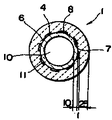
제1도는 본 발명에 의한 침지노즐의 정면 단면도.1 is a front cross-sectional view of the immersion nozzle according to the present invention.
제2도는 연결부의 보유면적이 5%인 경우의 중공실 전개 단면도.2 is a hollow chamber expanded cross sectional view when the retaining area of the connecting portion is 5%.
제3도는 연결부의 보유면적이 50%인 경우의 중공실 전개 단면도.3 is a hollow chamber expanded cross sectional view where the connection area is 50%.
제4도는 중공실내에 연결부를 설치한데 대해 실험결과에 의거한 전열특성 및 이론계산에 의거한 가스의 압력손실을 표시하는 선도.4 is a diagram showing the heat transfer characteristics based on the experimental results and the pressure loss of gas based on theoretical calculations for the connection part installed in the hollow chamber.
제5도는 제4도의 실험계측에 사용한 노즐구조의 단면도.5 is a cross-sectional view of the nozzle structure used for experimental measurement in FIG.
제6도는 연결부에 의한 전열면적, 가스유로의 길이 및 가스흐름의 압력손실과 관계를 표시하는 선도.6 is a diagram showing the relationship between the heat transfer area, the length of the gas flow path and the pressure loss of the gas flow by the connection part.
제7도는 연결부 부근에 있어서의 가스흐름을 표시하는 설명도이다.7 is an explanatory diagram showing gas flow in the vicinity of the connecting portion.
* 도면의 주요부분에 대한 부호의 설명* Explanation of symbols for main parts of the drawings
1 : 침지노즐 2 : 노즐본체1: immersion nozzle 2: nozzle body
3 : 슬랙라인용 보호통체 4 : 중공실3: protective cylinder for slack line 4: hollow chamber
6 : 연결부 7 : 외측벽부6
8 : 내측벽부 10 : 추출공8
본 발명은 가스취입(吹入)구조를 가지는 주조용 침지(浸漬)노즐 및 롱노즐의 개량에 관한 것이다.The present invention relates to improvements in casting immersion nozzles and long nozzles having a gas blowing structure.
최근, 용융금속의 연속주조에 있어서, 강철등의 품질향상이나 부착물에 의한 노즐 폐쇄방지등을 목적으로 하여, 침지노즐을 통하여 불활성가스등을 용융금속에 불어 넣는 침지노즐이 많이 사용되고 있다.Recently, in continuous casting of molten metal, immersion nozzles for blowing inert gas or the like into molten metal through immersion nozzles have been frequently used for the purpose of improving the quality of steel or the like and preventing the nozzle from being closed by deposits.
그 일례로서, 일본 특개소 56-102357호 공보에 기재된 침지노즐이 있다.As an example, there is an immersion nozzle described in Japanese Patent Laid-Open No. 56-102357.
이것은, 노즐본체의 축선방향으로 환상단면의 가스취입용 중공실(中空室)을 형성하고, 이 중공실로부터 가스를 침지노즐의 주출공(注出孔)내를 흐르는 용탕중(溶湯)에 불어넣는 구성이다.This forms a hollow chamber for gas blowing in an annular cross section in the axial direction of the nozzle body, and blows gas from the hollow chamber into the molten metal flowing in the pouring hole of the immersion nozzle. It is a composition to put.
또, 가스취입용의 중공실은, 내부에 소직경의 브리지를 구비하고 있어서, 이것에 의해 용탕압에 의한 중공실의 붕괴를 방지할 수가 있다. 그러나, 이 중공실은 공간이기 때문에 축심과 외주벽 사이에서 단열층으로 기능하여, 이 단열효과에 의해 중공실의 내측 내화물과 외측 내화물 사이에는 큰 온도차가 생기고, 이것에 기인하여 열응력이 발생하여, 보강용의 브리지를 설치하고 있어도 중공실 외측의 내화물이 파단될 우려가 있다.Moreover, the hollow chamber for gas blowing is provided with the bridge | bridging of small diameter inside, and can prevent the collapse of a hollow chamber by melt pressure by this. However, since this hollow chamber is a space, it functions as a heat insulation layer between the shaft center and the outer circumferential wall, and a large temperature difference is generated between the inner and outer refractory materials of the hollow chamber due to this thermal insulation effect, and thermal stress is generated due to this. Even if a dragon bridge is provided, the refractory on the outside of the hollow chamber may break.
본 발명의 목적은, 가스취입을 위해 중공실을 설치한 주조노즐에 있어서, 중공실 내외에 생기는 온도차를 저감하여 열응력에 의한 노즐본체의 붕괴를 방지하는데 있다.An object of the present invention is to prevent the collapse of the nozzle body due to thermal stress in a casting nozzle provided with a hollow chamber for gas blowing, by reducing a temperature difference occurring in and out of the hollow chamber.
본 발명은 노즐본체의 축선방향으로 가스취입용의 환상단면의 중공실을 형성함과 동시에 상기 중공실과 주출공과의 사이에 가스투과체를 배치하고, 또한 상기 중공실의 반경방향의 내측벽과 외측벽을 부분적으로 일체 연결하는 다수의 연결부를 설치한 가스취입형 주조노즐에 있어서, 연결부의 종단면적의 총계를 중공실의 전개면적의 대략 30 내지 70%로 한 것이다.The present invention forms a hollow chamber having an annular cross section for gas injection in the axial direction of the nozzle body, and also arranges a gas permeable body between the hollow chamber and the ejection hole, and also radially inner and outer walls of the hollow chamber. In the gas blown type casting nozzle provided with a plurality of connecting portions for partially connecting the plurality of parts, the total area of the connecting portions is approximately 30 to 70% of the development area of the hollow chamber.
이 구성에 의하면, 단열층으로서 기능하는 가스취입용 중공실에 연결부로 중공실의 내측벽과 외측벽을 부분적으로 연결함과 동시에, 이 연결부를 전열층으로서 기능시킴으로써 노즐본체의 반경방향의 온도차를 작게하여 열응력의 발생을 방지할 수 있다.According to this configuration, the inner wall and the outer wall of the hollow chamber are partially connected to the gas blowing hollow chamber functioning as the heat insulating layer, and the connecting portion functions as the heat transfer layer to reduce the radial temperature difference of the nozzle body. The generation of thermal stress can be prevented.
이하, 실험예에 의하여 본 발명의 구성 및 작용을 상세하게 설명한다.Hereinafter, the configuration and operation of the present invention by the experimental example will be described in detail.
침지노즐(1)은 제1도와 같이 축선방향으로 주출공(10)을 형성한 구조를 하고, 2는 원통형의 내화물로 이루어지는 노즐본체이고, 상기 노즐본체(2)는 그 중앙부에 슬랙 라인(slag line)용 보호통체(3)를 장착하고, 또한 주출공(10)에 면하여 가스투과체(11)를 설치하고 있다.The immersion nozzle 1 has a structure in which the
4는 노즐본체(2)의 내부에 있어서 가스투과체(11)의 외주측에 설치한 환상단면의 중공실이고, 이 중공실(4)의 상부에는 가스공급관(도시하지 않음)과 연통하는 소켓(5)이 배치되어 있다.4 is a hollow chamber of an annular cross section provided on the outer circumferential side of the gas permeable body 11 inside the
또, 6은 중공실(4)내를 반경방향으로 횡단하도록 위치하고, 노즐본체(2)측의 외측벽부(7)와 가스투과체(11)측의 내측벽부(8)와를 일체 연결하는 연결부이다. 이 연결부(6)는 가스투과체(11)로부터 외측의 노즐본체(2)방향으로 열전달하는 열전도대로서 기능하는 것으로, 그 재료는 노즐본체(2)와 동일한 내화물을 재료로서 성형하는 것이 바람직하다.In addition, 6 is located so as to traverse the inside of the
이러한 구성에 의해, 용탕이 주출공(10)내를 흐를때 내측벽부(8)가 보유하는 열은 연결부(6)에 의한 열전도에 의해 외측벽부(7)에 열전달이 된다.With this configuration, the heat retained by the inner wall portion 8 when the molten metal flows into the
이와 같이, 단열층으로 작용하는 중공실(4)의 일부를 가스의 통로를 저해하지 않도록 내화물로 된 연결부로 덮음으로써 적당한 전열효과를 가지게 하여, 열응력의 경감을 도모할 수가 있다.Thus, by covering a part of the
또, 이 연결부(6)의 배치는 중공실(4)내를 흘러 추출공(10)으로 분출하는 가스의 균일성, 노즐본체(2)에 생기는 열응력분포의 균일성을 도모하기 위해, 중공실(4)내의 상하방향 및 원주방향으로 균등하게 분산하는 것이 바람직하다.Moreover, in order to arrange | position the
제2도 및 제3도는 중공실(4)과 내화물로 된 전열부재로서 기능하는 연결부(6)의 배열 및 분포상태를 표시하는 부분전개도로, 각각 연결부(6)로 덮인 면적을 중공실(4)의 전개면적에 대하여 5%, 20%(도시하지않음) 및 50%로 한 것이다.2 and 3 are partial development diagrams showing the arrangement and distribution of the
상기 면적비의 구조를 노즐본체(2)에 적용하고, 주출공(10)내에 산소, LPG 버어너의 불꽃을 통하여 침지노즐(1)의 주출공(10)을 가열하고, 그 손상도를 비교하였다. 결과는, 제2도의 연결부(6)로 연결된 면적이 5%인 경우에서는 노즐본체(2)의 절손율이 100%인데 대하여, 제3도의 연결부(6)를 50%로 한 것에서는 절손이 전무하였다. 여기에서, 연결부(6)를 50%로 한 구조의 노즐본체(2)의 절손에 대한 안전성은 극히 높다는 것이 확인되었다.The area ratio structure was applied to the
제4도는 전열효과 및 압력손실의 특성을 표시하는 선도이고, 실선으로 표시하는 것은 노즐본체(2)의 단면구조가 제5도에 표시하는 바와 같이 예비성형한 가스투과체(11),중공실(4) 및 노즐본체(2)의 두께를 각각 10, 1, 25mm로 하고, 가스투과체(11)와 노즐본체(2)의 물성이 다음과 같은 경우의 실험치에 의해 얻은것이다.4 is a diagram showing the characteristics of the heat transfer effect and pressure loss, and the solid line shows the gas permeable body 11 and the hollow chamber preformed as shown in FIG. 5 by the cross-sectional structure of the

이 선도에 있어서 실선으로 표시한 전열특성은, 중공실(4)의 내측벽부(8)의 온도와 외측벽부(7)의 온도와의 온도차를 종축으로, 중공실(4)을 평면으로 전개한 경우에 내화물로 덮은 연결부(6)가 중공실(4)전체에서 점유하는 면적비율을 횡축으로 취하여 표시하였는데, 이 특성에 따르면 연결부(6)에 의한 전열면적이 중공실(4) 전체의 전개면적의 30% 미만인 경우 온도차가 급격히 크게 된다는 것이 확인되었다.In this diagram, the heat transfer characteristic indicated by the solid line indicates that the
또, 연결부(6)에 의한 전열면적이 중공실(4)의 면적의 30% 이상이면 온도차는 대략 50℃ 이내로 멈추고, 또한 40%의 영역에서는 온도구배는 더욱 작게 되며 100%일때의 온도차는 대략 0의 값에 점차 근접하는 것을 알 수 있다.When the heat transfer area by the connecting
따라서, 이 30 내지 40%의 범위가 전열효과의 인계점에 해당된다는 것이 확인되었다.Therefore, it was confirmed that this range of 30 to 40% corresponds to the take over point of the heat transfer effect.
또 상기 선도에 있어서 일점쇄선으로 표시한 것은, 중공부실(4)의 내경이 90mm, 길이가 415mm, 및 가스투과체(11)의 두께가 10mm인 전형적인 중공실 부착침지노즐에 있어서, 가스의 통로로 되는 내화물 기공을 수직원통으로 가정하고, 다음식으로부터 5Nl/min일때의 전열면적율과 사용시 가스압력에 대한 압력손실의 비율의 관계를 구한것을 플로트(Plot)한 것이다.In the above diagram, the dashed-dotted line indicates that the hollow chamber-attached immersion nozzle having an inner diameter of 90 mm, a length of 415 mm, and a thickness of the gas permeable body 11 is 10 mm. Assuming the refractory pores to be a vertical cylinder, the relationship between the heat transfer area ratio at 5 Nl / min and the ratio of pressure loss to gas pressure in use is calculated from the following equation.
![]()
![]()
![]()
![]()
여기서,here,

상기의 식(1),(2)에 있어서 l =100mm로 하면In the above formulas (1) and (2), l = 100 mm

의 계산치가 얻어지고, 이들의 수치를 플로트한 것이 일점쇄선으로 표시된 것이고, 이것은 전열 면적율과 압력손실과의 이론특성을 나타낸다.The calculated values of are obtained, and their values are plotted in dashed-dotted lines, indicating the theoretical characteristics of the heat transfer area ratio and the pressure loss.
이 특성에 의하면, 연결부(6)에 의한 전열 면적을이 70%를 초과하면 급격히 가스투과체(11)내에서 가스 흐름의 압력손실이 증가하여 취입가스의 압력을 높일 필요가 생기고, 그 결과 가스배관연결부에서의 가스누설의 위험성이나 연결부(6)의 형상에 따라서는 가스투과체(11)의 내벽면전체로부터 가스의 분출이 불균일하게 될 위험성이 증대하는 것을 알수 있다.According to this characteristic, if the heat transfer area of the connecting
이상의 실험 및 계산결과에 의해, 종래구조와 비교하여 압력손실의 면에서 문제를 일으키는 일이 없도록, 연결부(6)의 중공실(4)전체의 전개면적에 대한 종단면적, 즉 전열면적율의 상한율 70%로 하여 설정하였다.According to the above experiments and calculation results, the upper limit of the longitudinal area, that is, the heat transfer area ratio, to the development area of the entire
또, 이 압력손실에 관한 특성곡선은, 사용시의 가스취입압력의 최저치를 기준으로 한 비율로도 표시할 수가 있어서, 종축에 조업시의 가스압력 최저치에 대한 배압(背壓) 의 비율(단위 : %)로 상기 제4도의 선도에 병기하고 있다.Moreover, the characteristic curve regarding this pressure loss can also be displayed as the ratio based on the minimum value of the gas injection pressure at the time of use, and the ratio of the back pressure with respect to the minimum gas pressure value at the time of operation | movement to a vertical axis (unit: %) Is shown in the diagram of FIG.
그리고, 특성 곡선의 가스취입 압력이 최저치에 대한 비율을 사용함으로써, 계산에 사용한 노즐구조 이외의 형상, 재질 및 가스취입조건에도 적용된다는 것은 명백하다.And it is clear that the gas blowing pressure of the characteristic curve is also applied to shapes, materials and gas blowing conditions other than the nozzle structure used for the calculation by using the ratio to the minimum value.
제6도는 가스투과체(11)의 내벽면전체로부터의 가스의 균일한 분출을 얻기 위해 연결부(6)의 형상에 관한 제한을 표시하고, 또한, 연결부(6)에 의한 전열면적율을 변경했을때의 가스투과체(11)를 통과하는 가스의 압력손실과 가스의 유로(流路)길이와의 관계, 및 전열면적율과 압력손실과의 관계를 병기한 것이다.6 shows a restriction on the shape of the connecting
즉, 이 선도에 있어서, 곡선으로 표시한 것은 연결부(6)에 의한 전열면적과 가스흐름의 압력손실과의 관계를, 또 직선으로 표시한 것은 전열면적이 0 내지 90%인 경우의 가스통과거리와 압력손실과의 관계를 각각 표시하고, 또한 점선은 상기의 결과에 서 얻어진 전열면적의 상한인 70% 임계치를 표시하는 것이다.That is, in this diagram, the curve indicates the relationship between the heat transfer area by the connecting
또, 이 제6도와 선도에 있어서도 상기 제4도의 선도와 같이 압력손실에 관한 특성곡선은, 사용시의 가스취입압력의 최저치를 기준으로 한 비율로서도 표시할 수가 있어서 횡축에 조업시의 가스압력최저치에 대한 배압의 비율(단위 %)로 제6도의 선도에 병기하고 있다.Also, in FIG. 6 and the diagram, as shown in the diagram of FIG. 4, the characteristic curve on the pressure loss can also be expressed as a ratio based on the minimum value of the gas blowing pressure at the time of use. It is shown in the diagram of FIG. 6 by the ratio (unit%) of the back pressure.
여기서, 연결부(6)부근의 가스의 흐름은 제7도와 같이 추정할 수 있고, 연결부(6)의 중심부(중공실과 중공실의 사이)로의 가스의 유로(B)는 연결부(6)가 위치하지 않는 부분에서의 유로(A)보다도 길게 되어 압력손실이 커진다.Here, the flow of gas near the connecting
따라서 가스투과체(11) 내벽면전체로부터의 균일한 가스분출을 얻기 위하여 연결부(6)를 배치함으로써 전열면적율 증대와 동시에 유로(A,B)의 차(길이)를 작게함으로써, 유로(4,B) 사이의 압력손실의 차가 작게되어, 가스투과체(11) 내벽면전체로부터의 균일한 가스의 분출이 가능하게 되는 것을 알 수 있다.Therefore, by arranging the connecting
연결부(6)에 의한 전열면적이 30%인 경우에는, 이 유로의 비가 2.5 이상이 되면 유로(A,B)의 압력손실의 차가 커지고, 균일한 가스분출을 얻기 위하여서는 사용시의 최저가스압력이 종래의 가스압력의 1.1배를 초과하도록 할 필요가 있고, 이 때문에 가스유량을 증가시키지 않을 수 없다.In the case where the heat transfer area by the connecting
그러나, 가스유량을 증가시키면 노즐본체(2)의 주출공(10)벽에 생성된 석출물(析出物)을 괴상(塊狀)으로 박리시키는 결과를 초래하여 강의 품질 저하의 원인이 된다.However, increasing the gas flow rate causes the precipitates formed in the wall of the pouring
주형내에 들어간 가스에 의해 주형 탕면이 교란되어 용강(溶綱)에 주형파우더가 말려들어가는 등의 문제가 생긴다.The problem is that the mold hot water is disturbed by the gas inside the mold and the mold powder is rolled into the molten steel.
따라서 상기와 같이 가스의 유량의 증가는 조업에 지장을 초래하는 문제가 있어서 통상 작업에서는 가능한한 가스의 취입량이 최소인 것이 바람직하다.Therefore, there is a problem that the increase in the flow rate of the gas as described above causes a problem in the operation, it is preferable that the amount of gas blown in the normal operation as possible as possible.
따라서, 가스투과체(11) 내벽면전체로부터의 균일한 가스의 분출을 얻기 위하여 연결부(6)의 형상에 관한 제한의 하나로서 연결부(6) 상호의 간격은 상기 가스투과체(11) 두께의 2.5배 이하인 것이 바람직하다.Therefore, as one of the limitations on the shape of the
제6도의 연결부(6)에 의한 전열면적율을 변경했을 때의 가스투과체(11)를 통과하는 가스의 압력손실과 가스의 유로의 길이와의 관계는, 전열면적율과 압력손실과의 관계를 구한 식(1) 및 (2)에서 K를 변경했을 경우의 ℓ와 △P의 관계에서 구한 것이다.The relationship between the pressure loss of the gas passing through the gas permeable body 11 and the length of the gas flow path when the heat transfer area ratio by the connecting
[제실시예 1][Example 1]
중공실(4)의 내벽면적이 1100cm2, 가스투과체(11)의 두께가 10mm, 연결부(6)에 의한 중공실(4)전체에 대한 전열면적이 70%인 연속주조용 알루미나 흑연재질의 침지노즐을 제조하는데 있어서, 사전에 예비성형된 가스투과체(11)의 외주에 중공실(4)을 형성하는 소정 두께의 왁스를 도포한 후 이 왁스에 노즐축방향의 길이가 55mm, 둘레방향의 길이가 3mm인 직사각형의 구멍을 둘레방향으로 균등하게 78개, 축방향에 6개, 총계 468개 설치하였다.Alumina graphite material for continuous casting, wherein the inner wall area of the
이 가스투과체(11)를 용강유출공을 형성하는 코어(core)의 소정위치에 장착한 후, 본체를 성형하는 고무형(型)을 세트하고, 고무형내의 공간에 본체를 형성하는 소정재료를 충전하고, 뚜껑을 한 후, 고무프레스로서 1000kg/cm2의 압력으로 가압성형 하였다.After mounting the gas permeable body 11 at a predetermined position of a core forming the molten steel outflow hole, a rubber mold for molding the main body is set, and a predetermined material for forming the main body in a space in the rubber mold. After filling with the lid, it was press-molded at a pressure of 1000kg / cm 2 as a rubber press.
이후, 본 노즐을 코우크스분말에 넣어 환원소성시켜 본 발명인 전열면적 70%의 알루미나 흑연제 침지노즐을 얻었다.Subsequently, the nozzle was placed in a coke powder for reducing firing to obtain an immersion nozzle made of alumina graphite having a heat transfer area of 70% according to the present invention.
본 노즐을 수중에 담가 중공실(4)로 압력 0.4kg/cm2의 공기를 스며들게하고, 가스투과체(11)의 내벽으로부터의 가스가 나오는 양태를 관찰하여, 균일하게 거품이 나오는지를 확인하였다.The nozzle was immersed in water, soaked in air at a pressure of 0.4 kg / cm 2 into the
또한, 본 노즐을 실제 주조로에서 총량 2040톤의 용강주조에 사용하였다. 이때, 절손이나 노즐의 막힘이 없이 안전하게 사용되었다.In addition, this nozzle was used to cast 2040 tons of molten steel in actual casting furnace. At this time, it was used safely without breaking or clogging the nozzle.
또, 이 제조방법에 있어서 중공실 형성재료, 바인더 및 골재는 이하의 것이 사용된다.In addition, in this manufacturing method, the following are used for a hollow chamber formation material, a binder, and aggregate.
(1) 중공실 형성재료 :(1) Hollow chamber forming material:
마분지, 포목, 한국에서의 한지와 유사한 화지(和紙, Japanese paper) 등의 유기섬유로 이루어지는 원통형, 판형물 또는 왁스, 고무, 아크릴, 폴리에틸렌, 염화비닐, 스티롤 등의 유기화합물지를 이루어지는 원통형 판형물 또는, 이들 유기섬유 또는 유기화합물질을 미리 성형한 가스투과체(11)에 도포하여도 좋다.Cylindrical, plate-shaped articles made of organic fibers such as cardboard, lumber, Japanese paper similar to Korean paper in Korea, or cylindrical plate-shaped articles made of organic compound paper such as wax, rubber, acrylic, polyethylene, vinyl chloride, styrol, or These organic fibers or organic compounds may be applied to the gas permeable body 11 molded in advance.
(2) 바인더(binder) :(2) Binder
텍스트린, 펄프폐액, 당밀, 고즙등의 일반적 내화물에 사용되는 바인더, 또는 페놀수지등 소성시 또는 사용시의 열로 제거되어 내화물중에 남는 바인더.Binder used for general refractories such as unfilled, pulp waste liquid, molasses and high juice, or binders which are removed from the heat during firing or use of phenol resins and remain in the refractory.
(3) 골재(骨材) :(3) Aggregate (骨材):
일반 내화물에 사용되는 Al203, SiO2, MgO, ZrO2, MgOㆍAl203, SiC, 금속실리콘 등의 금속산화물 또는 탄화물 또는 질화물 또는 금속과 흑연의 1종 또는 2종 이상의 조합물.Metal oxides or carbides or nitrides such as Al 2 O 3 , SiO 2 , MgO, ZrO 2 , MgO · Al 2 O 3 , SiC, metal silicon used in general refractories, or a combination of one or two or more of metal and graphite .
[제실시예 2]Example 2
중공실을 가진 연속주조용의 알루미나 흑연제침지노즐을 제조함에 있어, 예비성형인 가스투과체(11)에 파라핀왁스를 소정두께로 도포하고, 파라핀왁스 도포면적 1239cm2의 50%에 상당하는 파라핀왁스에 직경 20mm의 독립한 구멍을 197개 뚫었다.In manufacturing alumina graphite immersion nozzle for continuous casting with a hollow chamber, paraffin wax is applied to the preformed gas permeable body 11 to a predetermined thickness, and paraffin equivalent to 50% of the application area of paraffin wax 1239 cm 2 . 197 independent holes with a diameter of 20 mm were drilled into the wax.
다음에, 가스투과체(11)를 침지노즐의 용강유출공을 형성하는 금형으로 끼워맞춘후, 노즐본체(2)를 형성하는 고무형과 이 금형의 간극에 노즐본체(2)의 재료를 투입하고, 뚜껑을 하여 밀봉한 뒤 고무프레스에 투입하여 가압성형후 소성한다.Next, after fitting the gas permeable body 11 into a mold for forming the molten steel outflow hole of the immersion nozzle, the material of the
또한, 본 노즐을 실제 주조로에서 총량 1750톤의 용강주조에 사용 하였다.In addition, this nozzle was used to cast 1750 tons of molten steel in the actual casting furnace.
이때에, 절손이나 노즐의 막힘이 없이 안전하게 사용 되었다.At this time, it was used safely without breakage or clogging of the nozzle.
[제실시예 3]Example 3
알루미나ㆍ흑연질인 주성분을 갖는 소정입도(粒度)의 원료를 소정입도로 분쇄하여 소정비율로 조합하고, 페놀수지를 가해서 혼합한 재료와, 중공실(4)의 형성물, 요컨대 외주면적 346cm2의 소정두께의 원통형 마분지에, 그의 면적의 35%에 상당 하도록 직경 30mm의 구멍을 15개 뚫은 것을 금형의 소정위치에 투입하고, 고무프레스에 의해 가압하고 성형하였다.A raw material having a predetermined particle size having an alumina-graphite main component was pulverized to a predetermined particle size, combined at a predetermined ratio, and mixed with a phenol resin to form a material of the
다음에, 이 성형물을 건조후 소성하여 본 발명의 침지 노즐을 얻었다.Next, this molded product was dried and fired to obtain the immersion nozzle of the present invention.
또한, 본 노즐을 실재 주조로에 총량 1020톤의 용강주조에 사용하였다. 이때, 절손이나 노즐의 막힘이 없고 안전하게 사용되었다.In addition, this nozzle was used for casting molten steel of a total amount of 1020 tons in the actual casting furnace. At this time, there was no breakage or clogging of the nozzle and it was used safely.
본 발명에 관한 가스취입형 주조노즐은 그 구성에 의해 하기의 효과가 있다.The gas blown casting nozzle according to the present invention has the following effects by its configuration.
(1) 중공실내에 열전도대로서도 기능하는 연결부를 설치하여 중공실을 둘러싼 외측벽부와 내측벽부간의 전열을 효과적으로 행할 수가 있어서, 온도차에 의한 침지노즐의 손괴를 확실하게 방지할 수 있다.(1) A connecting portion which also functions as a heat conduction band in the hollow chamber can be provided to effectively conduct heat transfer between the outer wall portion and the inner wall portion surrounding the hollow chamber, thereby preventing damage to the immersion nozzle due to a temperature difference.
(2) 가스의 압력손실이 중대하지 않는 범위로 연결부를 설치하기 때문에, 가스공급압을 크게할 필요가 없다.(2) Since the connection is provided in a range where the pressure loss of gas is not significant, it is not necessary to increase the gas supply pressure.
Claims (1)
Applications Claiming Priority (3)
| Application Number | Priority Date | Filing Date | Title |
|---|---|---|---|
| JP???60-105888 | 1985-07-10 | ||
| JP105888 | 1985-07-10 | ||
| JP1985105888U JPH0224510Y2 (en) | 1985-07-10 | 1985-07-10 |
Publications (2)
| Publication Number | Publication Date |
|---|---|
| KR870000982A KR870000982A (en) | 1987-03-10 |
| KR900005272B1 true KR900005272B1 (en) | 1990-07-27 |
Family
ID=14419457
Family Applications (1)
| Application Number | Title | Priority Date | Filing Date |
|---|---|---|---|
| KR1019860005508A KR900005272B1 (en) | 1985-07-10 | 1986-07-08 | Gas-blow casting nozzle |
Country Status (6)
| Country | Link |
|---|---|
| US (1) | US4746038A (en) |
| JP (1) | JPH0224510Y2 (en) |
| KR (1) | KR900005272B1 (en) |
| BE (1) | BE905078A (en) |
| BR (1) | BR8603246A (en) |
| DE (1) | DE3622866C2 (en) |
Families Citing this family (14)
| Publication number | Priority date | Publication date | Assignee | Title |
|---|---|---|---|---|
| DE3714680A1 (en) * | 1987-05-02 | 1988-11-17 | Didier Werke Ag | FIRE-RESISTANT WEAR PARTS FOR SPOUT CLOSURES |
| CH675088A5 (en) * | 1987-12-24 | 1990-08-31 | Stopinc Ag | |
| US4836508A (en) * | 1988-05-03 | 1989-06-06 | Vesuvius Crucible Company | Ladle shroud with co-pressed gas permeable ring |
| US5188689A (en) * | 1989-05-01 | 1993-02-23 | Ferro Corporation | Method of forming a porous refractory immersion nozzle |
| US5100035A (en) * | 1989-05-01 | 1992-03-31 | Ferro Corporation | Permeable MgO nozzle |
| CA2063994C (en) * | 1989-05-01 | 2001-06-12 | Bruce Dunworth | Permeable mgo nozzle |
| JPH0734977B2 (en) * | 1990-02-20 | 1995-04-19 | 黒崎窯業株式会社 | Immersion nozzle for continuous casting |
| US6016941A (en) * | 1998-04-14 | 2000-01-25 | Ltv Steel Company, Inc. | Submerged entry nozzle |
| DE19900915A1 (en) * | 1999-01-13 | 2000-07-20 | Schloemann Siemag Ag | Method and device for setting and / or maintaining the temperature of a melt, preferably a steel melt during continuous casting |
| KR20020052614A (en) * | 2000-12-26 | 2002-07-04 | 이구택 | Device for uniformly supplying the inert gas of upper nozzle |
| AU2003254783B2 (en) * | 2002-07-31 | 2008-10-16 | Shinagawa Refractories Co., Ltd. | Casting nozzle |
| JP4925888B2 (en) * | 2007-03-27 | 2012-05-09 | 京セラ株式会社 | Rotating body for molten metal stirring, and molten metal degassing apparatus using the same |
| CN102489679A (en) * | 2011-12-29 | 2012-06-13 | 上海宝明耐火材料有限公司 | Anti-blocking water feeding port with low air permeability |
| JP6292869B2 (en) * | 2013-12-26 | 2018-03-14 | 黒崎播磨株式会社 | Long nozzle manufacturing method |
Family Cites Families (7)
| Publication number | Priority date | Publication date | Assignee | Title |
|---|---|---|---|---|
| FR1094517A (en) * | 1953-11-25 | 1955-05-20 | Casting plant for molten metals | |
| GB834234A (en) * | 1955-09-19 | 1960-05-04 | Patentverwertung Ag | Process and device for the production of high-quality castings |
| US3253307A (en) * | 1964-03-19 | 1966-05-31 | United States Steel Corp | Method and apparatus for regulating molten metal teeming rates |
| JPS5140260Y2 (en) * | 1974-05-11 | 1976-10-01 | ||
| JPS56102357A (en) * | 1980-01-16 | 1981-08-15 | Toshiba Ceramics Co Ltd | Immersion nozzle for gas blowing type continuous casting |
| IT1191099B (en) * | 1981-12-09 | 1988-02-24 | Mannesmann Ag | IMMERSION CASTING SPOUT AND ITS USE |
| GB8313074D0 (en) * | 1983-05-12 | 1983-06-15 | Thornton J M | Refractory product |
-
1985
- 1985-07-10 JP JP1985105888U patent/JPH0224510Y2/ja not_active Expired
-
1986
- 1986-07-07 US US06/882,662 patent/US4746038A/en not_active Expired - Lifetime
- 1986-07-08 KR KR1019860005508A patent/KR900005272B1/en not_active IP Right Cessation
- 1986-07-08 DE DE3622866A patent/DE3622866C2/en not_active Revoked
- 1986-07-09 BE BE0/216898A patent/BE905078A/en not_active IP Right Cessation
- 1986-07-10 BR BR8603246A patent/BR8603246A/en not_active IP Right Cessation
Also Published As
| Publication number | Publication date |
|---|---|
| BR8603246A (en) | 1987-02-24 |
| DE3622866A1 (en) | 1987-01-22 |
| KR870000982A (en) | 1987-03-10 |
| DE3622866C2 (en) | 1994-10-06 |
| JPH0224510Y2 (en) | 1990-07-05 |
| US4746038A (en) | 1988-05-24 |
| JPS6215849U (en) | 1987-01-30 |
| BE905078A (en) | 1986-11-03 |
Similar Documents
| Publication | Publication Date | Title |
|---|---|---|
| KR900005272B1 (en) | Gas-blow casting nozzle | |
| KR960015336B1 (en) | Casting spout for metallurgical vessels | |
| CA1191325A (en) | Pouring of molten metals | |
| US5691061A (en) | Refractory shape having an external layer capable of forming a layer impermeable to gases and process for its preparation | |
| US4401243A (en) | Charging a mold for continuous casting | |
| EP0503316A2 (en) | Erosion, thermal shock and oxidation resistant refractory compositions | |
| US4368834A (en) | Preheating device for stopper-type tundishes | |
| JPS591229B2 (en) | Immersion nozzle for continuous casting of molten steel | |
| US4243210A (en) | Tundish for the continuous casting of steel | |
| KR20130100160A (en) | Floor casting nozzle for arrangement in the floor of a metallurgical container | |
| GB1449902A (en) | Teeming steel for continuous casting | |
| KR100874397B1 (en) | Fire plug for injecting gas into the molten metal | |
| JPH0212664B2 (en) | ||
| US3810564A (en) | Air pressure discharge furnace having protective atmosphere inlet and outlet | |
| GB2099119A (en) | A porous plug for use in a vessel for molten metal | |
| US4455014A (en) | Production of refractory linings or walls | |
| JPH04270037A (en) | Nozzle for continuous casting | |
| US4244420A (en) | Apparatus for feeding a horizontal continuous casting mold | |
| GB2150868A (en) | Porous plug assemblies for molten metal vessels e.g. ladles | |
| US10926320B2 (en) | Transition plate | |
| US4724985A (en) | Teeming ladles | |
| JPS583467B2 (en) | How do you know how to proceed? | |
| JPS6160247A (en) | Preheater for immersion nozzle for continuous casting | |
| US3329201A (en) | Pouring tube for pressure pouring apparatus | |
| JPH0510183B2 (en) |
Legal Events
| Date | Code | Title | Description |
|---|---|---|---|
| A201 | Request for examination | ||
| E902 | Notification of reason for refusal | ||
| G160 | Decision to publish patent application | ||
| E701 | Decision to grant or registration of patent right | ||
| GRNT | Written decision to grant | ||
| FPAY | Annual fee payment |
Payment date: 20030624 Year of fee payment: 14 |
|
| LAPS | Lapse due to unpaid annual fee |