KR890003304B1 - Three-phase power factor controller with induced emf sensing - Google Patents
Three-phase power factor controller with induced emf sensing Download PDFInfo
- Publication number
- KR890003304B1 KR890003304B1 KR1019830005362A KR830005362A KR890003304B1 KR 890003304 B1 KR890003304 B1 KR 890003304B1 KR 1019830005362 A KR1019830005362 A KR 1019830005362A KR 830005362 A KR830005362 A KR 830005362A KR 890003304 B1 KR890003304 B1 KR 890003304B1
- Authority
- KR
- South Korea
- Prior art keywords
- motor
- voltage
- output
- operational amplifier
- power factor
- Prior art date
Links
Images


Classifications
-
- H—ELECTRICITY
- H02—GENERATION; CONVERSION OR DISTRIBUTION OF ELECTRIC POWER
- H02J—CIRCUIT ARRANGEMENTS OR SYSTEMS FOR SUPPLYING OR DISTRIBUTING ELECTRIC POWER; SYSTEMS FOR STORING ELECTRIC ENERGY
- H02J3/00—Circuit arrangements for ac mains or ac distribution networks
- H02J3/18—Arrangements for adjusting, eliminating or compensating reactive power in networks
- H02J3/1892—Arrangements for adjusting, eliminating or compensating reactive power in networks the arrangements being an integral part of the load, e.g. a motor, or of its control circuit
-
- H—ELECTRICITY
- H02—GENERATION; CONVERSION OR DISTRIBUTION OF ELECTRIC POWER
- H02P—CONTROL OR REGULATION OF ELECTRIC MOTORS, ELECTRIC GENERATORS OR DYNAMO-ELECTRIC CONVERTERS; CONTROLLING TRANSFORMERS, REACTORS OR CHOKE COILS
- H02P23/00—Arrangements or methods for the control of AC motors characterised by a control method other than vector control
- H02P23/26—Power factor control [PFC]
-
- H—ELECTRICITY
- H02—GENERATION; CONVERSION OR DISTRIBUTION OF ELECTRIC POWER
- H02P—CONTROL OR REGULATION OF ELECTRIC MOTORS, ELECTRIC GENERATORS OR DYNAMO-ELECTRIC CONVERTERS; CONTROLLING TRANSFORMERS, REACTORS OR CHOKE COILS
- H02P2201/00—Indexing scheme relating to controlling arrangements characterised by the converter used
- H02P2201/15—Power factor Correction [PFC] circuit generating the DC link voltage for motor driving inverter
Abstract
Description
제1도는 본 발명의 유기 기전력 감지회로를 사용한 역률 제어장치를 부분적으로 도시한 회로의 블록 다이어 그램.1 is a block diagram of a circuit partially showing a power factor control device using the organic electromotive force sensing circuit of the present invention.
제2(a)도-제(i)도는 제1도의 장치의 작동을 설명하기 위한 파형도.2 (a)-(i) are waveform diagrams for explaining the operation of the apparatus of FIG.
본 발명은 장치의 성능을 개선하는데 이용되는 유기 기전력 감지 기능을 갖는 역률형 전동기 제어장치에 관한 것이다.The present invention relates to a power factor type motor control apparatus having an organic electromotive force sensing function used to improve the performance of the apparatus.
본 출원인 명의로된 "교류 유도전동기용 역률 제어장치"라는 표제의 미국 특허 제 4,052,648호에는 전동기의 작동역률이 검사되고 전동기에 입력되는 실효전압이 제어 역률신호와 작동 역률간의 편차 함수로서 제어되는 유도 전동기의 전력감소 장치가 기재되어 있다. 동출원인의 1981년 2월 17일자로 출원한 "삼상 역률 제어 장치"라는 표제의 한국특허출원 제 489/81호(특허 제 17787호)에는 삼강유도 전동기에 특히 적합한 역률형 제어장치가 기술되어 있다. 또한, 동출원일이 1982년 8월 12일자로 출원한 "감소전압 시동기가 구비된 전동기 역률 제어장치"라는 표제의 한국 특허 출원 제 3618/82호(특허 제 24723호)에는 역률제어장치의 전동기를 " 유연하게(soft)"시동시키는 시동회로가 기술되어 있다. 비록 이들 장치들이 경부하 전동기에서 에너지 소모를 상당히 감소시키는 역할을 할지라도, 상이한 전동기들간의 많은 변화로 인하여 가능한 최대의 절약이 항상 실현될 는 없는 문제점이 있었다.U.S. Patent No. 4,052,648 entitled "Power Factor Control Device for AC Induction Motors" in the name of the applicant discloses that the operating power factor of the motor is checked and the effective voltage input to the motor is controlled as a function of deviation between the control power factor signal and the operating power factor. An apparatus for reducing power of an electric motor is described. Korean Patent Application No. 489/81 (Patent No. 17787) entitled "Three-Phase Power Factor Control Device" filed February 17, 1981, filed with the same applicant, describes a power factor type control device particularly suitable for Samkang induction motors. . In addition, Korean Patent Application No. 3618/82 (Patent No. 24723) entitled "Motor power factor control device with a reduced voltage starter" filed on August 12, 1982, filed with an application for a power factor control device motor. A starting circuit is described that starts "soft". Although these devices serve to significantly reduce energy consumption in light load motors, there is a problem that the maximum savings possible are not always realized due to the large number of changes between different motors.
본 발명은 에너지가 더욱 절약되고 부하의 급격한 변화에 대한 응답속도가 더욱 신속하며 전동기의 유연한 시동특성을 더 향상시킨 개선된 역률 제어장치(PFC)를 목적으로 하는 것이다. 이하 더 상세히 설명되듯이, 본 발명은 그 가장 광범위한 의미에 있어서 전동기의 유기 기전력을 감지하고 그로부터 전동기의 작동을 제어하는데 사용되는 피이드백 신호를 유도하는 것을 포함한다. 이 같이 개선된 결과를 얻는데 필요한 회로는 전반적으로 삼상 PFC 대한 가격의 1%및 단상 PFC에 대한 가격의 3%미만이다.The present invention aims at an improved power factor control (PFC) device that further saves energy, responds faster to sudden changes in load, and further improves the flexible starting characteristics of the motor. As will be explained in more detail below, the present invention encompasses in its broadest sense the induction of feedback signals used to sense the organic electromotive force of the motor and to control the operation of the motor therefrom. The circuit required to achieve this improved result is less than 1% of the price for a three-phase PFC and less than 3% of the price for a single-phase PFC overall.
본 발명의 바람직한 실시예에 의하면, 본 발명은 전동기와 직렬 연결되는 전자 스위칭 수단(예컨데, 다이리스터), 전동기 전류 및 전압을 감지하고, 그 전류와 전압간의 위상차에 비례하는 출력을 공급하기위한 위상 검출기 수단, 역률 제어신호를 발생하는 제어 신호 발생수단, 및 전자 스위칭 수단의 스위칭 상태를 제어하기위해 위상 검출기 수단의 출력 및 역률 제어신호에 응답하는 제어수단을 포함하는 형태의 교류 유도 전동기용 역률 제어장치에 사용되고 ,일반적으로 전자스위칭 수단이 오프(off)상태인 각 반 싸이클의 시간 간격동안 전동기에 의해 감지된 유기 기전력에 따라, 전자 스위칭 수단의 스위칭을 제어하기위해 사용될 피이드백 신호를 만들어내기 위한 수단과를 포함한다.According to a preferred embodiment of the present invention, the present invention provides an electronic switching means (e.g., a thyristor) connected in series with a motor, a phase for sensing an electric current and voltage and supplying an output proportional to the phase difference between the current and voltage. Power factor control for an AC induction motor comprising a detector means, a control signal generation means for generating a power factor control signal, and a control means for responding to an output of the phase detector means and a power factor control signal for controlling the switching state of the electronic switching means. To generate a feedback signal to be used in the device and to be used to control the switching of the electronic switching means according to the organic electromotive force sensed by the motor during the time interval of each half cycle in which the electronic switching means are generally off. Means;
상기 감지수단은 전동기의 부하에 의해 야기되는 전동기 전압파형에서 극성의 반전을 바람직하게 감지하고 스위칭 수단의 "오프"기간중에 발생된 유기 기전력이 스위칭 수단의 "온(on)"기간중에 발생된 전압에 반대극성으로 되는 각 반 싸이클의 간격동안을 제외하고 출력이 저지 되는 고이득 연산 증폭기를 포함한다.The sensing means preferably detects an inversion of the polarity in the motor voltage waveform caused by the load of the motor and the organic electromotive force generated during the "off" period of the switching means is a voltage generated during the "on" period of the switching means. It includes a high-gain op amp whose output is blocked except for the interval of each half cycle, which becomes antipolar.
삼상 전동기와 함께 사용되기에 적합한 바람직한 실시예에 있어서, 감지수단은 전자 스위칭 회로의 스위칭을 제어하기위해 선전압단자와 전자 스위칭 회로사이에 연결되는 구형파 전압성형회로, 전자 스위칭 회로의 제어하에서 전동기에 비례하는 전압을 중성 전압으로 증폭 및 선택적으로 반전시키기 위해 전자스위칭 회로를 통해 전동기의 중성 전압단자에 연결되는 고이득 연산 증폭기 및 연산 증폭기의 출력이 제1극성으로 될 때 그 출력을 저지하기 위한 다이오드 수단을 포함한다.In a preferred embodiment suitable for use with a three-phase motor, the sensing means is a square wave voltage shaping circuit connected between the line voltage terminal and the electronic switching circuit for controlling the switching of the electronic switching circuit. Diodes for suppressing the output of the high gain op amp and op amp connected to the neutral voltage terminal of the motor through the electronic switching circuit to amplify and selectively invert the proportional voltage to the neutral voltage when the output becomes the first polarity. Means;
전자 스위칭 회로는 제어 전극이 구형파 성형회로의 출력단에 연결되는 제1 및 제2트랜지스터를 포함하며, 그 트랜지스터들 각각은 연산 증폭기의 한 입력단에 병렬로 연결되는 것이 바람직하다. 상기 다이오드 수단을 연산증폭기의 출력단에 연결된 다이오드를 포함하는 것이 바람직하다. 이 실시예에서, 역률 제어장치는 상기 언급한 세개의 위상 검출기 수단을 이용하며 이들 위상 검출기 수단의 출력단들은 가산 접합점에 연결된다. 감지수단은 또한 연산 증폭기의 전압출력을 저장하고 연산 증폭기의 출력 저지에 응답하는 대응 전압을 방전하기 위하여 이 가산 접합점에 연결되는 커패시터 수단을 포함한다. 이 커패시터 수단은 커패시터, 커패시터를 충전함에 있어서 그 커패시터를 보조하기 위한 플로우어(follower)를 포함한다.The electronic switching circuit includes first and second transistors whose control electrodes are connected to the output terminal of the square wave shaping circuit, each of which is preferably connected in parallel to one input terminal of the operational amplifier. Preferably, the diode means comprises a diode connected to the output of the operational amplifier. In this embodiment, the power factor controller utilizes the three phase detector means mentioned above and the output ends of these phase detector means are connected to an addition junction. The sensing means also includes capacitor means connected to this additive junction to store the voltage output of the operational amplifier and discharge the corresponding voltage in response to the output rejection of the operational amplifier. This capacitor means comprises a capacitor, a follower for assisting the capacitor in charging the capacitor.
상기 전동기의 시동 특성을 개선하기 위해 전동회로수단을 포함하는 역률 제어장치와 함께 사용되는 본 발명의 또 하나의 특징에 의하면, 전동기의 시간에 대한 속도의 비례성을 개선하는 방식으로 시동회로수단의 출력에 영향을 주도록 감지수단의 출력단이 시동회로수단에 연결된다. 시동회로수단은 시간에 대한 전동기의 속도를 제어하기위해 램프 전압을 발생하도록 워상각 피이드백 회로를 포함하는 것이 바람직하며 감지수단의 출력은 램프전압과 가산된다. 감지수단은 한 극성의 출력신호를 저지하기 위해 상기 연산 증폭기의 출력단에 연결되는 다이오드와 전동기의 시동에 응답하여 충전되고 전동기가 제속도에 다달을때 방전되며 다이오드를 통해 상기 연산 증폭기의 출력단에 연결되는 커패시터를 포함한다.According to another feature of the present invention used in conjunction with a power factor control device including an electric circuit means for improving the starting characteristic of the electric motor, the starting circuit means may be The output end of the sensing means is connected to the starting circuit means so as to influence the output. The starting circuit means preferably comprises a warp angle feedback circuit to generate a ramp voltage to control the speed of the motor over time and the output of the sensing means is added to the ramp voltage. The sensing means is charged in response to the start of the motor and the diode connected to the output terminal of the operational amplifier to block the output signal of one polarity and is discharged when the motor reaches the speed and connected to the output terminal of the operational amplifier via the diode. And a capacitor.
전자 스위칭 수단이 예컨대 다이리스터를 포함하는 또 한가지 실시예에서, 감지수단은 그 다이리스터의 양단에 연결되어 그 양단의 전압을 감지한다. 이 실시예어서, 감지수단은 제 1 연산 증폭기와 제 2 연산 증폭기를 포함하며, 여기서, 제1연산증폭기의 입력단들은 상기 다이리스터 양단에 연결시키고 제 2 연산증폭기는 제1연산증폭기의 출력을 정류시킨다.In another embodiment, in which the electronic switching means comprise, for example, a thyristor, the sensing means is connected across both ends of the diester to sense the voltage across it. In this embodiment, the sensing means comprises a first operational amplifier and a second operational amplifier, wherein the inputs of the first operational amplifier are connected across the die Lister and the second operational amplifier rectifies the output of the first operational amplifier. Let's do it.
또 다른 실시예에서, 감지수단은 연산증폭기를 포함하며, 그의 입력단들이 제각기 반대 극성의 다이오드를 거쳐 전동기와 전자 스위칭 수단간의 접합점에 연결된다.In yet another embodiment, the sensing means comprises an operational amplifier whose inputs are connected to the junction between the motor and the electronic switching means via diodes of opposite polarities, respectively.
제1도에서, 삼상 전동기(10)는 단자(A,B,C)로부터 대표적으로 220(또는 440)볼트, 60싸이클의 교류 전압을 공급하는 삼상 전력선에서 트라이액 소자(110.112,111)를 통해 전력을 공급받는다. 전류는 각기 전동기(10)의 입력단과 직렬로 연결된 저항(20,22,24)에 의해 분로된 전류 샘플링 변압기(26,28,30)에 의하여 샘플 되어진다. 변압기(26,28,30)는 이들 저항들 중 하나의 양단에 각각 연결되고(도시된 바와같이 1차권선을 통하여), 하나의 2차단자는 접지되며, 나머지 2차 단자(X,Y또는 Z)는 위상이 상이한 전류신호 출력을 공급한다. 단자(X)는 A상, 단자(Z)는 B상, 그리고 단자(Y)는 C상과 결합된다.In FIG. 1, the three-phase motor 10 is typically 220 (or 440) volts from terminals A, B, and C, via a triac element 110.112, 111 in a three phase power line supplying an alternating voltage of 60 cycles. Get power. The current is sampled by current sampling transformers 26, 28, 30, respectively, separated by resistors 20, 22, 24 connected in series with the input of motor 10. Transformers 26, 28, and 30 are connected to both ends of one of these resistors (through the primary winding as shown), one secondary terminal is grounded, and the other secondary terminal (X, Y or Z) is grounded. ) Supplies a current signal output that is out of phase. Terminal X is coupled to A phase, terminal Z to B phase, and terminal Y to C phase.
역률신호, 즉 삼상 입력 각각의 전류-저압 위상차에 비례하는 신호는 위상 검출기들(122,124,126)에 의하여 개별적으로 얻어진다. 위상 검출기(122)는 단자(X)로부터 A상 전류를 나타내는 전류응답 신호 샘플을, 그리고 변압기(38)로부터 A-B상 전압을 나타내는 전압신호를 받아서 ,단자(142)에 제 1 위상 검출 출력을 공급한다. 위상 검출기(124)는 단자(Z)로부터 B상 전류를 나타내는 샘플을, 그리고 변압기(42)로부터 B-C전압 샘플을 받아서 단자(142)에 제 2 위상 검출 출력을 공급한다. 위상 검출기(126)는 단자(Y)로 부터 C상 전류 신호샘플을, 그리고 변압기(44)로부터 C-A상 전압 샘플을 받아서 단자(142)에 제 3 위상 검출 신호를 공급한다. 저항(130)(132) 및 커패시터(134)는 한국 특허출원 제489/81호에 설명된 바와같이 입력신호를 위상 천이시키는데 사용된다.The power factor signal, i.e., a signal proportional to the current-low voltage phase difference of each of the three phase inputs, is obtained separately by the phase detectors 122, 124 and 126. The phase detector 122 receives a current response signal sample representing the A phase current from the terminal X and a voltage signal representing the AB phase voltage from the transformer 38, and supplies a first phase detection output to the terminal 142. do. The phase detector 124 receives a sample representing the B phase current from the terminal Z and a B-C voltage sample from the transformer 42 and supplies a second phase detection output to the terminal 142. Phase detector 126 receives a C-phase current signal sample from terminal Y and a C-A phase voltage sample from transformer 44 and supplies a third phase detection signal to terminal 142. Resistor 130,132 and capacitor 134 are used to phase shift the input signal as described in Korean Patent Application No. 489/81.
위상 검출기들(122,124,126)은 서로 동일하며 상기 특허출원에 기술된 형태로 될 수 있다.The phase detectors 122, 124, 126 are identical to each other and may be in the form described in the patent application.
위상 검출기들(12,124,126)의 출력은 단자(142)에서 가산되고, 신호 조절 회로(150)가 마련되어 신호의 직류 특성이 다이리스터 트리서 회로와 양립되면서도 50헬츠정도까지의 적절한 주파수 응답을 갖도록 만들어지는 단자(142)에서 발생된 제어신호로 신호를 조절한다.The outputs of the phase detectors 12, 124, 126 are added at the terminal 142, and a signal conditioning circuit 150 is provided so that the direct current characteristic of the signal is compatible with the thyristor-trisser circuit and has a suitable frequency response up to about 50 hertz. The signal is controlled by the control signal generated at the terminal 142.
제어신호를 전위차게(70)로 부터 저항(68)을 통해 공급되는 역률제어 신호와 함께 연산 증폭기(151)의 반전 입력단으로 인가된다. 전위차게(70)는 음(-)으로 바이어스되어 위상 검출기의 출력단에 나타나는 양(+)의 신호에 대하여 편차 또는 감산 신호를 공급한다. 신호 조절은 한국 특허출원 제 489/81호에 기술된 바와 같이 리드-래그 소자들(lead-lag components)(152,154,156,158,160,162)을 포함한 역 피이드 백 회로에 의해 이루어진다.The control signal is applied to the inverting input terminal of the operational amplifier 151 together with the power factor control signal supplied from the potential difference 70 through the resistor 68. The potential difference 70 is negatively biased to provide a deviation or subtraction signal with respect to the positive signal appearing at the output of the phase detector. Signal conditioning is accomplished by an inverse feed back circuit including lead-lag components 152, 154, 156, 158, 160 and 162 as described in Korean Patent Application No. 489/81.
다이리스터(트라이액) 트리거 신호는 연산 증폭기(151)의 제어신호출력과 램프 발생기(116,118,120)에 의하여 공급되는 램프 신호와를 비교함으로써 나타난다. 각 상으로부터의 120헬츠 램프 신호는 제각기 변압기(38,42,44)로부터의 A-B,B-C 및 C-A상 전압에 응답하여 종래의 램프 발생기(116,118,120)에 의하여 나타난다. 이들 발생기의 램프출력은 연산증폭기(151)로부터의 제어신호와 함께 개별적으로 종래의 비교기(90,92,94)에 인가된다. 작동중에, 비교기는 제어신호의 레벨의 램프신호의 전단과 교차할때 출력펄스를 공급한다. 이 펄스는 다이리스터를 트리거한다.The thyristor (triac) trigger signal is shown by comparing the control signal output of the operational amplifier 151 with the ramp signal supplied by the ramp generators 116, 118, 120. 120 Hertz lamp signals from each phase are represented by conventional lamp generators 116, 118 and 120 in response to A-B, B-C and C-A phase voltages from transformers 38, 42 and 44, respectively. The ramp outputs of these generators are separately applied to conventional comparators 90, 92 and 94 together with control signals from operational amplifier 151. In operation, the comparator supplies an output pulse when it crosses the front end of the ramp signal at the level of the control signal. This pulse triggers the thyristor.
다이리스터의 전류 "턴 온(turn on)"기간의 실제적인 제어는 비교기(90,92,94)의 출력에 응답하여 고주파 신호를 통과시키는 게이트(96,98,100)에 의하여 이루어진다. 게이트(96,98,100)는 전자 스위치이며 고주파 발전기(102)로부터 변압기(104,106,108)의 일차권선을 통해 다이리스터로 고주파신호(예컨대, 10킬로헬츠)를 게이드하는 작용을 한다. 저항(110)과 다이오드(112)는 유도성 전압을, 사용된 반도체 회로와 조화되는 안전한 레벨로 억제하기위하여 각 변압기의 알차권선 양단에 직렬로 연결된다. 변압기(104,106,108)의 이차권선을 트라이액 소자)110,112,111)의 게이트와 캐소우드 사이에 연결된다. 트라이액의 턴온 기간은 예컨대 비교기(90,92,94)의 펄스 출력기간에 뒤따른다. 저항(113)과 커패시터(114)는 트라이액 스위치의 작동을 안정시키기 위하여 트라이액 스위치 각각의 전력 단자 양단에 직렬로 연결된다.The actual control of the current "turn on" period of the thyristors is made by gates 96, 98, 100 which pass high frequency signals in response to the outputs of comparators 90, 92, 94. Gates 96, 98 and 100 are electronic switches and function to gate high frequency signals (e.g., 10 kilohealth) from the high frequency generator 102 to the thyristor through the primary windings of the transformers 104, 106 and 108. Resistor 110 and diode 112 are connected in series across the primary winding of each transformer to suppress the inductive voltage to a safe level that matches the semiconductor circuit used. Secondary windings of the transformers 104, 106 and 108 are connected between the gate and the cathode of the triac elements 110, 112 and 111. The turn on period of the triac follows, for example, the pulse output period of the comparators 90, 92, 94. A resistor 113 and a capacitor 114 are connected in series across the power terminals of each of the triac switches to stabilize the operation of the triac switch.
지금까지 설명한 회로는 한국 특허출원 제 489/81호에 기술된 회로와 일치화며 비교하기 쉽도록 사용된 참조부호는 상기 특허의 제5도에서 사용된 참조후보들과 전반적으로 일치시켰다. 그외에도, 한국 특허출원 제3618/82호에 기술된 것과 일치하는 더욱 감소된 전압 시동기 회로가 사용되며 참조부호는 상기 특허출원의 제1도에 사용된 것들과 일치시켰다. 이 후자 특허출원에 설명되었듯이, 전동기(10)가 시동회로가 작동하기 전에 턴"온"이 되지 않도록 하기 위하여, 전시동 기간중에 정상"가동"제어 신호의 인가를 방지하기 위한 회로가 마련된다. 이것은 PNP트랜지스터(158)를 저항(68)과 또 하나의 저항(69)사이의 전위차계(70)양단에 콜렉터-에미터 연결함에 의하여 이루어진다. 트랜지스터(158)이 턴"온"될때, 전위차계(70)는 실제로 단락된다.The circuits described so far are consistent with the circuits described in Korean Patent Application No. 489/81 and the reference numerals used for easy comparison are generally consistent with the reference candidates used in FIG. Besides, a further reduced voltage starter circuit is used which is consistent with that described in Korean Patent Application No. 3618/82 and reference numerals are consistent with those used in Figure 1 of the above patent application. As described in this latter patent application, a circuit is provided for preventing the application of the normal "run" control signal during the exhibition run period, in order to prevent the motor 10 from being turned "on" before the start circuit operates. . This is accomplished by connecting the PNP transistor 158 to the collector-emitter across the potentiometer 70 between the resistor 68 and another resistor 69. When transistor 158 is turned "on", potentiometer 70 is actually shorted.
트랜지스터(158)는 트랜지스터(158)의 베이스에 연결된 저항(160)을 통하여 연산 증폭기(162)로부터 제어된다. 연산 증폭기(162)의 음(-)바이어스를 비반전(+)입력단에 인가하므로써 이루어진다. 비반전(+)입력단에 인가되는 바이어스는 저항(164)(166)으로 형성된 전압 분할기이 의해 분할된 15볼트 전원의 미리정해진 퍼센트로 되는 고정된 바이어스이다.Transistor 158 is controlled from operational amplifier 162 through resistor 160 coupled to the base of transistor 158. The negative bias of the operational amplifier 162 is applied to the non-inverting (+) input terminal. The bias applied to the non-inverting (+) input is a fixed bias that is a predetermined percentage of the 15 volt power source divided by the voltage divider formed by resistors 164 and 166.
처음에 연산 증록기(162)의 반전(-)입력단에 인가되는 전압은"0"으로서, 시동 램프 발생기를 형성하는 또 하나의 연산 증폭기(182)의 초기 출력이며, 이 같은 상태에서, 전위는 연산 증폭기(182)의 비반전(+)입력단에서 더욱 크다. 전우차게(168)는 저항(170)을 통하여 단자(172)에 초기 시동 레벨의 음(-)신호를 공급하며 ,단자(172)에서 이 신호는 저항(176)을 통한 연산 증폭기(182)으로부터의 음(-)으로되는 시동 램프 신호에 가산된다.The voltage initially applied to the inverting (-) input of operational amplifier 162 is " 0 ", which is the initial output of another operational amplifier 182 forming a start ramp generator, in which state the potential is Larger at the non-inverting (+) input of operational amplifier 182. Power supply 168 supplies a negative signal of the initial starting level to terminal 172 via resistor 170, which is fed from op amp 182 through resistor 176 at terminal 172. Is added to the negative start ramp signal.
NPN트랜지스터(178)는 단자(172)와 접지사이에 이미터-콜렉터 연결되며, 시동 사이퀸스가 완료된 후에 시동 신호로부터 저지효과를 차단하기 위한 수단이 제공된다. 트랜지스터(178)는 저항(180)을 통한 연산 증폭기(162)로부터의 출력에 의해 제어되며,연산 증폭기(162)로부터의 음(-)출력에 의해 시동 시이퀸스 중 초기에 "오프"로 유지된다.NPN transistor 178 is an emitter-collector connected between terminal 172 and ground, and provides a means for blocking the blocking effect from the start signal after the start sequence is complete. Transistor 178 is controlled by the output from operational amplifier 162 through resistor 180, and remains " off " initially during startup sequence by a negative output from operational amplifier 162. .
커패시터(184)는 연산 증폭기(182)의 출력단으로 부터 반전(-)입력단에 연결되어 적분기를 형성한다. +15볼트 단자와 접지사이에 연결된 전위차계(186)로부터 선정된 양(+)바이어스가 얻어진다. 이 바이어스는 입력정항(192)을 통하여 연산 증폭기(182)의 반전(-)입력단에 공급된다. 그 결과, 상기 회로에 전압이 인가됨에 따라 연산 증폭기(182)의 출력단에는 이 바이어스와 커패시터(184) 및 입력 저항(192)의 시정수에 의해 결정되는 선정된 속도로 음(-)램프 다운되는(ramp down)기본적으로 "0"으로 전압이 처음으로 나타나서 바람직한 속도의 전도기 "턴 온"신호를 얻는다. 연산 증폭기(182)의 출력단에서 음(-)으로 되는 신호를 저항(176)을 통하여 단자(172)로 공급되고 그곳에서 저항(170)을 통하여 공급되는 전위차계(168)로부터의 전압에 가산된다. 그 다음에 이 신호는 저항(183)을 통하여 단자(142)에 인가되고 그곳에서 작동 역률신호(또는 전류 저압 위상각)와 가산되며 연산 증폭기(151)에 인가되어 대체로 5-30초의 기간에 걸쳐서 점차적으로 실효 전동기 전압을 전 전압까지 상승시키게 되는 증가되는 (음(-)으로)제어신호로 된다. 제어신호에 의한 다이리스터의 실제적인 작동제어는 한국특허출원 제 3618/82호에 더 상세히 기술되어 있다.The capacitor 184 is connected to the inverting (−) input terminal from the output terminal of the operational amplifier 182 to form an integrator. The selected positive bias is obtained from the potentiometer 186 connected between the +15 volt terminal and ground. This bias is supplied to the inverting (-) input terminal of the operational amplifier 182 through the input definition 192. As a result, as voltage is applied to the circuit, the output of the operational amplifier 182 is negatively ramped down at a predetermined rate determined by the bias and time constants of the capacitor 184 and the input resistance 192. By default, the voltage first appears at "0" to get the conductor "turn on" signal at the desired speed. A negative signal at the output of the operational amplifier 182 is added to the voltage from the potentiometer 168, which is supplied via a resistor 176 to a terminal 172 where it is supplied through a resistor 170. This signal is then applied to terminal 142 via resistor 183, where it is added with an operating power factor signal (or current low voltage phase angle) and applied to operational amplifier 151 over a period of approximately 5-30 seconds. It gradually becomes an increasing (negative) control signal that raises the effective motor voltage to full voltage. The actual operation control of the thyristor by the control signal is described in more detail in Korean Patent Application No. 3618/82.
이 경우, 연산 증폭기(182)의 출력은 또한 연산 증폭기(162)의 반전(-)입력단에도 인가되고, 그 출력이 연산 증폭기(162)의 비반전(+) 입력단에 인가된 레벨을 넘는 레벨까지 상승할때 연산증폭기(162)의 출력은 음(-)상태로부터 양(+)상태로 전환된다. 이 변화된 상태가 스위칭 전위로서 트랜지스터(178,158)로 공급되어 트랜지스터(178)를 "턴 온"하고 트랜지스터(158)를 "턴 오프"한다. 그 결과 트랜지스터(178)는 어떠한 시동신호라도 단자(172)에서 나타는 것을 방지하고 트랜지스터(158)는 전위차계(70)의 출력을 차단하지 않아서 전동기(10)의 "가동"을 위한 정상적인 역률제어를 복귀한다.In this case, the output of the operational amplifier 182 is also applied to the inverting (-) input terminal of the operational amplifier 162 to a level above that applied to the non-inverting (+) input terminal of the operational amplifier 162. When rising, the output of the operational amplifier 162 transitions from a negative state to a positive state. This changed state is supplied to transistors 178 and 158 as switching potentials to " turn on " transistor 178 and " turn off " As a result, the transistor 178 prevents any start up signal from appearing at the terminal 172 and the transistor 158 does not block the output of the potentiometer 70 to achieve normal power factor control for " commissioning " To return.
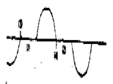
제2(a)도-제2(i)도에 도시한 파형을 보면, 전동기 단자로부터 위상 제어된 전동기의 중성점으로 나타나는 전압파형이 제2(b)도에 도시되어 있는 반면에 전류는 제2(a)도에 도시된다. 다이리스터가 오프이고 전류가 흐르지 않는 도면 부호(1)(2)로 표시된 기간중에, 전동기 저압은 "0"이 아니고 한정된 값을 가지는 것을 알 수 있다. 다이리스터(트아리액)가 오프인때 전동기 단자 양단에 나타나는 전압은 회전자에 흐르는 전류에 의하여 고정자 권선에 유기되는 역 기전력이다. 농형 회전자의 L/R시정수는 고정자의 시정수보다 훨씬 크며, 대체로 0.1 또는 0.2초이다. 그러므로, 고정자 전류가 지점(3)(4)에서 흐르는 것이 중지한다고 할지라도, 회전자에는 간격(1)(2)동안 고정자에 전압을 유기시키는 전류가 아직 흐른다.Referring to the waveforms shown in Figs. 2 (a) to 2 (i), the voltage waveform represented by the neutral point of the motor controlled phase from the motor terminal is shown in Fig. 2 (b) while the current is (a) is shown in FIG. It can be seen that during the period indicated by reference numerals (1) (2) in which the thyristors are off and no current flows, the motor low pressure is not " 0 " and has a limited value. The voltage appearing across the motor terminals when the thyristor is off is the counter electromotive force induced in the stator winding by the current flowing through the rotor. The L / R time constant of the cage rotor is much larger than that of the stator, which is usually 0.1 or 0.2 seconds. Thus, even if the stator current stops flowing at points 3 and 4, the rotor still flows with current that induces voltage to the stator during the interval 1 and 2.
이 유기된 전압의 진폭은 두가지 요인, 즉, 속도와 전류가 흐르는 것을 중지하는 지점에 따라 크게 좌우된다. 유기된 역 기전력은 속도의 함수이므로, 전동기가 속도를 늦추려는 경향으로 인해 유기된 전압의 진폭을 감소시키게된다. 더우기, 트라이액이 그 주기내에서 곧 턴 오프된다면, 그때 유기된 고장자 전류로 인해 회전자에서 더 작은 전류가 유기되게하고, 따라서 간격(1) (2)동안 더 작은 전압이 유기되게 한다.The amplitude of this induced voltage is highly dependent on two factors: speed and the point at which the current stops flowing. Since the induced back EMF is a function of speed, the tendency of the motor to slow down reduces the amplitude of the induced voltage. Furthermore, if the triac is turned off soon within that period, then the induced fault current causes the smaller current to be induced in the rotor, thus causing the smaller voltage to be induced during the interval (1) (2).
전술한 출원에서는 전류와 전압간의 위상각이 전동기에 부하가 걸릴때 어떻게 감소되는지를 설멍한 것이다. 역률제어장치로 제어된 전동기가 위상복귀되어 최대에너지 절약을 성취한다면, 이 장치는 부하의 커다란 급격한 변화에 순간적으로 대응하는 능력을 잃는다. 장치가 부하의 커다란 급격한 변화에 대응하기 위해서는 어느정도의 절약이 희생되어야 한다.The above application describes how the phase angle between current and voltage is reduced when the motor is loaded. If a motor controlled by a power factor control is phased back to achieve maximum energy savings, the device loses its ability to react instantaneously to large, rapid changes in load. Some savings must be sacrificed for the device to respond to large, rapid changes in load.
위상 제어된 전동기에 급격히 부하가 걸리고 그 장치가 응답하기에 충분히 빠르지 않다면, 그때 두가지 문제점이 발생한다. 첫째로, 위상각이 감소하는데, 이것은 곧 트라이액이 턴 오프되어 제2(a)도에서 좌측으로 이동하는 지점(3)(4)으로 표시된 전류 종지점이 된다는 것을 의미한다. 전술한 바와같이, 이것으로 인해 유기된 전압이 감소되게 한다. 두째로, 전동기 속도는 늦어지는데, 이것은 또한 유기 전압이 감소되게 하는 결과가 된다. 따라서, 부하의 급격한 변화로 인해 유기 전압에 순간적이고 상당한 변화를 일으킨다. 이러한 전압을 감지하고, 감지된 전압을 제어장치로 보냄으로써, 이 장치는 위상이 더뒤어질 수 있어서 절약을 증가시키나 부하의 급격한 변화에 그래도 응답하여 전동기의 실속을 방지한다. 일반적으로, 이것이 본 발명의 기본 목적인 것이다.If the phase controlled motor is suddenly loaded and the device is not fast enough to respond, then two problems arise. Firstly, the phase angle decreases, which means that the triac is turned off and becomes the current end point indicated by the points 3, 4 moving to the left in FIG. 2 (a). As mentioned above, this causes the induced voltage to be reduced. Secondly, the motor speed is slowed, which also results in reduced induced voltages. Thus, a sudden change in load causes a momentary and significant change in the induced voltage. By sensing this voltage and sending the sensed voltage to the control device, the device can be out of phase to increase the savings but prevent the motor from stalling in response to sudden changes in the load. In general, this is the basic purpose of the present invention.
제2(c)도는 보면, 위상 제어된 공전 삼상 전동기의 중성 전압에 대한 대표적인 위상 파형이 도시되어있다. 다이리스터의 오프기간중 유기기전력은 다이리이스가 각 반 사이클내에서 "온"일때의 전압에 실제로 반대 극성으로 된다는 것을 알 수 있다. 이것은 다른 두 위상으로부터 중성전압에 대한 위상이 가산되어 이같은 경우에, 이 장치가 그 부하에 응답하여 위상이 앞선 후에, 그 극성 반전은 제2(d)도에 도시한 바와같이 일어나지 않는다. 공전하는 전동기에 급격히 부하가 결린다면, 극성 반전된 전압은 제2(c)도에 점선으로 표시된 바와같이 증가한다.Figure 2 (c) shows a representative phase waveform for the neutral voltage of a phase controlled idle three phase motor. It can be seen that the organic electromotive force during the off period of the thyristors is actually the polarity opposite to the voltage when the thyris is "on" within each half cycle. This adds the phase to the neutral voltage from the other two phases and in this case, after the device is out of phase in response to its load, its polarity reversal does not occur as shown in FIG. 2 (d). If there is a sudden load on the idle motor, the polarity inverted voltage increases as indicated by the dotted line in FIG. 2 (c).
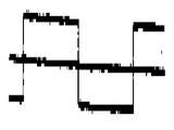
제1도의 장치에 부가된 회로는 이러한 극성 반전된 전압만을 검출하고 이 전압을 에너지 절약 및 응답속도를 개선하기 위하여 사용하도록 대비한 것이다. 따라서, 제1도를 다시보면, 연산 증폭기(A1)는 한국 특허 출원 제 489/81호에 설명된 위상 검출기에 사용된 전압 구형차 성형회로(+)이다. 점(a)에 표시된 전압은 중성 전압에 대한 전동기 전압이다. 이러한 전압이 마디(b)에서 (R1)(R2)에 의하여 적절한 레벨로 강하된다. 연산 증폭기(A1)의 출력단을 저항(R12)을 통하여 제 1 트랜지스터(Q1)의 베이스에 그리고 저항(R13)을 통하여 제 2 트랜지스터(Q2)의 베이스에 접속된다. 제2(f)도에 도시된 바와같이, 연산 증폭기(A1)의 출력이 양(+)일때, 제어 트랜지스터(Q1)는 온되어서 어떠한 신호라도 제 2 연산 증폭기 (A2)의 음(-)입력단에 안가되는 것을 방지한다. 연산 증폭기(A1)의 출력이 음(-)일때, 트랜지스터(Q2)가 온이되어 신호가 연산 증폭기(A2)의 양(+)입력단에 인가되는 것을 방지 한다. 저항(R3,R4,R5,R6,R7)의 값들은 연산 증폭기(A2)의 이득이 그 양(+) 및 음(-) 단자 모두의 입력들에 대하여 동일하게 되도록 선정된다. 연산 증폭기(A1)의 출력이 양(+)일때, 증폭기(A2)는 점(b)에서의 전압을 양(+)이득으로 증폭한다. 증폭기(A1)의 출력이 음(-)일때, 증폭기(A2)는 점(b)에서의 전압을 반전시키고 이 전압을 음(-)이득을 증폭하여서 제2(e)도에 도시된 전파 정류 전압으로 된다. 연산 증폭기(A2)의 출력이 음(-)으로 되는 유일한 경우는 전술한 바와같이 유기 기전력이 반대 극성으로 되는 각 반 싸이클내의 그 기간중이다. 이러한 것이 검출되어져야할 사항이다.The circuit added to the apparatus of FIG. 1 is intended to detect only this polarity inverted voltage and use this voltage to save energy and improve response time. Thus, referring back to FIG. 1, the operational amplifier A1 is a voltage squarer shaping circuit (+) used in the phase detector described in Korean Patent Application No. 489/81. The voltage indicated at point (a) is the motor voltage with respect to the neutral voltage. This voltage is dropped to an appropriate level by node (R1) (R2) at node b. The output terminal of the operational amplifier A1 is connected to the base of the first transistor Q1 through the resistor R12 and to the base of the second transistor Q2 through the resistor R13. As shown in FIG. 2 (f), when the output of the operational amplifier A1 is positive, the control transistor Q1 is turned on so that any signal has a negative input terminal of the second operational amplifier A2. To avoid being on When the output of the operational amplifier A1 is negative, the transistor Q2 is turned on to prevent the signal from being applied to the positive input terminal of the operational amplifier A2. The values of resistors R3, R4, R5, R6, and R7 are selected such that the gain of operational amplifier A2 is the same for the inputs of both its positive and negative terminals. When the output of operational amplifier A1 is positive, amplifier A2 amplifies the voltage at point b by positive gain. When the output of amplifier A1 is negative, amplifier A2 inverts the voltage at point b and amplifies this voltage to a negative gain, thereby full-wave rectification shown in FIG. 2 (e). It becomes a voltage. The only case where the output of the operational amplifier A2 becomes negative is during that period within each half cycle in which the organic electromotive force becomes opposite polarity as described above. This should be detected.
증폭기(A2)의 양(+)출력은 단지 음(-)출력만을 통과시키는 다이오드(D1)에 의해 저지된다. 급격한 부하가 걸린 경우 이 음(-)전압은 제2(e)도에 점선으로 표시된 바와같이 순간적으로 증가한다.The positive output of amplifier A2 is blocked by diode D1 which only passes the negative output. In case of a sudden load, this negative voltage increases instantaneously as indicated by the dotted line in FIG.
이러한 음(-) 피이크(peak)는 공전하는 전동기에서 거의 "0"값이므로, 상당한 이득이 증폭기(A2)에 포함될 수 있어서 부하의 급격한 변화로 생기는 유기 기전력의 증가는 또한 증폭될 수 있어서 그것의 효율을 증가시킨다는 것을 알 수 있다. 이것이 본 발명의 중요한 목적인 것이다.Since this negative peak is almost " 0 " in an idle motor, a significant gain can be included in the amplifier A2 so that the increase in organic electromotive force resulting from a sudden change in load can also be amplified so that It can be seen that the efficiency is increased. This is an important object of the present invention.
증폭기(A2)로부터의 음(-) 펄스는 다이오드(D1)로 통과되고, 증폭기(A2)의 출력단에 저항이 없으므로 커패시터(C1)에 피이크값까지 순간적으로 충전된다. 또 하나의 연산 증폭기(A3)가 전압 플로우어로서 접속되어 커패시터(C1)에 고입력 임피던스를 공급하여 커패시터(C1)이 각 반 싸이클 사이에서 충전을 유지할 수 있게 하여서 맥동을 제거한다. 증폭기(A3)의 출력은 커패시터(C3)와 저항(R9) (R10)의 병렬 조합을 통하여 증폭기 입력단자(142)로 공급된다.The negative pulse from the amplifier A2 is passed to the diode D1, and since there is no resistance at the output terminal of the amplifier A2, the capacitor C1 is momentarily charged up to the peak value. Another operational amplifier A3 is connected as a voltage flower to supply high input impedance to the capacitor C1 so that the capacitor C1 can maintain charge between each half cycle to eliminate pulsations. The output of amplifier A3 is supplied to amplifier input terminal 142 through a parallel combination of capacitor C3 and resistor R9 (R10).
이와같은 배치로서, 급격한 부하는 유기 기전력 회로에 의해 순간적으로 감지되고 조절되어 역률제어장치로 공급되는 신호가 만들어져서 역률제어장치가 부하에 응답하게 한다. 일단 역률제어장치가 부하에 응답하여 위상이 앞서게 되면, 전동지 전압은 제2(d)도에 표시된 형태로 될 것이다.With this arrangement, the sudden load is instantaneously sensed and adjusted by the organic electromotive force circuit to produce a signal to the power factor controller to cause the power factor controller to respond to the load. Once the power factor controller is in phase in response to a load, the field voltage will be in the form shown in Figure 2 (d).
이같은 상황하에서, 어떠한 전압도 커패시터(C1)에 인가되지 않고, 커패시터(C1)은 즉시 그것의 충전신호를 병렬 연결된 저항(R8)으로 흘려보내기 시작한다. 이러한 상황이 발생되면, 충전신호는 부하 충격계수에 대해, 커채시터(C1)가 다음에 급격히 인가되는 부하에 응답하여 충전될 수 있는 레벨까지 급속히 줄어든다. 커패시터(C1)와 저항(R8)에 의해 이루어진 RC회로의 시정수는 전형적으로 역률제어장치와 전동기 제어장치에 관련된 주파수에 비해 높은 수 초이다.Under such a situation, no voltage is applied to the capacitor C1, and the capacitor C1 immediately starts to flow its charging signal to the parallel connected resistor R8. When this situation occurs, the charge signal rapidly decreases with respect to the load shock coefficient to a level at which the capacitor C1 can be charged in response to a load that is rapidly applied next. The time constant of the RC circuit formed by the capacitor C1 and the resistor R8 is typically a few seconds higher than the frequencies associated with the power factor controller and the motor controller.
유기 기전력 감지회로는 한 방향으로 신속하게 작동하므로 신속히 증가하고 천천히 감소됨), 그 회로로부터의 출력신호는 그 장치의 안정성에 영향을 미치지 않고 큰 이득으로 역률제어장치 제어 시스템에 공급될 수 있다. 큰 이득은 성능을 개선하는데 있어서 유기 기전력의 실효성을 증가시키며, 전술한 바와같이, 이것은 본 발명의 주요한 목적인 것이다. 이러한 이득은 커패시터(C3)와 저항(R10)에 의하여 결정되는 한편 저항(R9)커패시터(C3)에서 충전신호를 방출하는 역할을 한다.The organic electromotive force sensing circuit operates rapidly in one direction and therefore increases rapidly and decreases slowly), and the output signal from the circuit can be supplied to the power factor controller control system with great gain without affecting the stability of the device. A large gain increases the effectiveness of the organic electromotive force in improving performance, and as mentioned above, this is the main object of the present invention. This gain is determined by the capacitor C3 and the resistor R10, and serves to emit a charging signal from the resistor R9 capacitor C3.
그러므로, 지금까지 설명된 회로는 급격한 부하에 대한 응답속도를 개선하는 한편 본 장치가 에너지를 더욱 절약하도록 위상이 더욱 늦추어질 수 있게 한다. 유기 기전력은 또한 제1도의 PFC시스템에 사용되어 전동기의 완만한 시동 특성을 개선한다. 이상적으로 완만한 시동은 속도가 시간에 비례하여 증가하는 것이다. 진술한 완만한 시동회로로써 위상각 피이드백은 시스템의 안정화를 위하여 사용된다. 전동기 속도가 증가함에 따라 위상각은 감소하므로, 이것으로 인해 인가되는 전압이 증가되고 다시 속도가 시간에 따라 더 큰 속도로(비례적인 아니라)증가된다. 이같은 방법이 대부분의 용도에 충분하지만, 본 장치는 유기 기전력 신호를 피이드백하고 이 신호를 완만한 시동램프 전압과 가산하므로써 더 개선될 수 있다. 이 같은 목적으로, 증폭기(A2)의 출력단으로부터 다이오드(D2), 커패시터(C3) 및 저항(R11)을 통하여 상술된 연산 증폭기(182)의 램프 출력단으로 접속이 이루어진다.Therefore, the circuit described so far improves the response speed to sudden loads, while allowing the device to be slower in phase to further save energy. Organic electromotive force is also used in the PFC system of FIG. 1 to improve the smooth starting characteristics of the motor. Ideally a slow start is a speed increase in proportion to time. With the slow start-up circuit stated, phase angle feedback is used to stabilize the system. As the motor speed increases, the phase angle decreases, thereby increasing the applied voltage and in turn increasing the speed at a higher speed (not proportionally) over time. While this method is sufficient for most applications, the device can be further improved by feeding back the organic electromotive force signal and adding this signal to a gentle starting ramp voltage. For this purpose, a connection is made from the output of amplifier A2 to the lamp output of operational amplifier 182 described above via diode D2, capacitor C3 and resistor R11.
본 발명의 이같은 목적을 더 상세히 살펴보면, 전동기가 정지상태에서 위상 제어 전압이 인가될때, 전동기 전압파형은 제2(g)도에 도시된 값에 단계적으로 접근한다. 그러므로, 증폭기(A2)에의해 발생된 펄스는 실속중에 크게 시작되어 전동기의 정격속도에서 "0"으로 줄어든다. 다이오드(D2)는 연산 증폭기(A2)의 양(+)출력을 저지한다. 따라서, 커패시터(C3)에는 전동기가 처음 시동될때 대전압까지 충전되고, 이 전압은 전동기가 제속도에 이름에 따라 감소한다. 이 전압이 연산 증폭기(182)에 의해 만들어진 시동램프와 가산되어서 초기에 대시동 전압이 제어된다. 이 제어 전압은 속도가 증가함에 따라 감소한다. 이 같은 작동으로 인해 인가된 전동기 전압이 감소되게하고 전술한 위상각에 의하여 야기된 인가 전압의 증가에 반작용을 하며, 상기 위상각은 속도에 따라 감소한다. 따라서 시간에 대해 더 비례적인 속도 특성이 얻어진다.Looking at this object of the present invention in more detail, when the phase control voltage is applied in a stationary state of the motor, the motor voltage waveform approaches the value shown in Fig. 2 (g) step by step. Therefore, the pulse generated by the amplifier A2 starts large during stall and decreases to "0" at the rated speed of the motor. Diode D2 blocks the positive output of operational amplifier A2. Thus, the capacitor C3 is charged to a large voltage when the motor is first started, and this voltage decreases according to the name of the motor at speed. This voltage is added to the starting lamp made by the operational amplifier 182 so that the dash-dong voltage is initially controlled. This control voltage decreases with increasing speed. This operation causes the applied motor voltage to be reduced and reacts to the increase in the applied voltage caused by the aforementioned phase angle, which phase decreases with speed. Thus a more proportional speed characteristic is obtained with respect to time.
결합된 "완만한 시동"회로의 전체 작동을 다시 살펴보면, 본 시스템의 초기 턴 온 시에 적분기(182)의 출력은 "0"볼트이다. 비교기(162)의 출력은 그 음(-)입력단에 나타나는 "0"볼트와 저항(166)(164)에 의해 형성된 저항 강하를 통하여 그 양(+)입력단에 임가되는 음(-)전압에 의해서 완전히 음(-)으로 된다. 이 같은 조절하에서, NPN 트랜지스터(178)는 베이스 전압이 음(-)이 되어 그 전압은 통과할 수 있으므로 "오프"될 것이다. PNP트랜지스터(158)는 베이스 전압이 음(-)이므로 "온"될 것이다. 이것은 전위차계(70)로 부터의 또는 본 발명의 유기 기전력 피이드백 회로의 연산 증폭기(A2)의 출력단으로부터의 또는 가산 단자(142)에 있는 연산 증폭기(151)의 입력단으로부터의 어떠한 전압도 억제한다.Looking back at the overall operation of the combined "slow start" circuit, the output of integrator 182 at the initial turn on of the system is "0" volts. The output of the comparator 162 is driven by the negative voltage applied to its positive input terminal through the resistance drop formed by the resistors 166 and 164 and the "0" bolt appearing at its negative input terminal. It is completely negative. Under this adjustment, NPN transistor 178 will be " off " because the base voltage is negative and can pass therethrough. PNP transistor 158 will be "on" because the base voltage is negative. This suppresses any voltage from potentiometer 70 or from the output of operational amplifier A2 of the organic electromotive force feedback circuit of the invention or from the input of operational amplifier 151 at addition terminal 142.
초기 턴온시에, 그리고 커패시터(78) 및 저항(76)의 시정수에 의해 결정되는 대체적으로 20밀리초의 지속기간 동안, 적분기(151)의 출력은 음(-)으로 구동되어 다이리스터의 너무 빠른 점호를 방지한다. 동시에, 두 전압, 즉, 전위차계(168)로부터의 저항(170)을 통한 전압과 저항(R11)을 통한 유기 기전력 신호가 가산점(142)으로 공급된다. 이들 신호는 전동기를 천천히 시동하는 초기 시동 전류를 제어한다. 이들 전압 모두는 음(-)인 것에 유의해야한다. 상이한 부하에 필요한 시동전류의 양은 전위차계(168)에 의해 변화될 수 있다. 또한, 초기 턴온시에 적분 연산 증폭기(182)는 적분, 즉 그것의 출력전압 증가를 음(-)으로 시작한다. 이 출력이 다른 두 전압과 가산되고 전동기 속도가 증가함에 따라 전동기 전류를 증가시킨다. 본 발명의 유기 기전력이 다른 두 전압과 가산되고 전동기 속도가 증가함에 따라 전동기 전류를 증가시킨다. 본 발명의 유기 기전력 회로로부터의 전압이 감소하고 전동기 속도가 시간에따라 더 비례적으로 증가하게하는 것은 이 같은 속도로 증가중이다. 커패시터(184)와 저항(192) 및 전위차계(186)로부터의 전압에 의해 결정되는 적분 연산 증폭기(182)의 출력은 대체적으로 초당 1볼트 증가하고 전동기는 5-10초가 지나면 전속도로된다.At initial turn-on and for a duration of approximately 20 milliseconds, determined by the time constants of capacitor 78 and resistor 76, the output of integrator 151 is driven negatively so that the thyristor is too fast. Prevent firing. At the same time, two voltages, i.e., the voltage through the resistor 170 from the potentiometer 168 and the organic electromotive force signal through the resistor R11, are supplied to the addition point 142. These signals control the initial starting current that starts the motor slowly. Note that all of these voltages are negative. The amount of starting current required for the different loads can be varied by potentiometer 168. In addition, at initial turn-on, the integral operational amplifier 182 starts the integration, i.e., increasing its output voltage negatively. This output is added to the other two voltages and increases the motor current as the motor speed increases. The organic electromotive force of the present invention is added to the other two voltages and the motor current increases as the motor speed increases. It is increasing at this rate that the voltage from the organic electromotive force circuit of the present invention decreases and the motor speed increases more proportionally with time. The output of the integral operational amplifier 182, determined by the voltage from the capacitor 184 and the resistor 192 and the potentiometer 186, generally increases by one volt per second and the motor is at full speed after 5-10 seconds.
전동기가 최종속도에 이른후에, 연산 증폭기(182)로 부터의 전압은 연산 증폭기(162)의 양(+)입력단에서의 전압을 초과하여서 연산 증폭기(162)를 완전히 양(+)으로 전환시킨다. 이 작동으로해서 가산 접합점(142)으로부터의 모든 시동전압을 억제하는 트랜지스터(178)를 턴"온"한다. 그 작동으로해서 또한 전위차계(70)로 부터의 제어와 본 발명의 유기 기전력 전압이 실효성이 있도록 트랜지스터(158)를 턴"오프"한다.After the motor reaches its final speed, the voltage from the operational amplifier 182 exceeds the voltage at the positive input terminal of the operational amplifier 162 to completely convert the operational amplifier 162 to positive. This operation turns on the transistor 178 which suppresses all the starting voltages from the addition junction 142. This operation also turns " off " the transistor 158 so that the control from the potentiometer 70 and the organic electromotive force voltage of the present invention are effective.
유기 기전력을 감지하기위한 다른 실시예에서, 다이리스터 양단의 전압이 감지된다. 다이리스터 전압은 선전압에서 전동기 전압을 뺀것과 같고 따라서 유기 기전력이 다이리스터 전압에서 나타나기 때문에 이같은 변형이 가능한 것이다.In another embodiment for sensing organic electromotive force, the voltage across the thyristor is sensed. The thyristor voltage is equal to the line voltage minus the motor voltage, so this variation is possible because the organic electromotive force appears at the thyristor voltage.
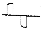
위상제어 전동기의 대표적인 다이리스터 전압이 제2(h)도에 도시된다. 간격(1) )(2)에서의 진폭은 장치가 부하의 증가에 응답하여 위상이 앞설때 감소하고, 부하가 제어될때 장치가 위상이 뒤짐에따라 감소한다. 전동기가 실속하고 있을때 유기 기전력은 "0"이므로, 다이리스터 전압은 최대로 전동기가 제속도에 이름에따라 감소한다. 따라서, 이 전압은 전술한 바와같이 완만한 시동을 개선하는데 사용된다. 급격이 인가된 부하가 전동기의 속도를 늦추는 경향이 있다면, 트라이액 양단의 전압은 순간적으로 상승하며 전술한 바와같이 역률제어 장치가 응답하게하는데 사용된다.A representative thyristor voltage of the phase control motor is shown in FIG. 2 (h). The amplitude at intervals 1) and 2 decreases when the device is out of phase in response to an increase in load and decreases as the device is out of phase when the load is controlled. Since the organic electromotive force is "0" when the motor is stalled, the thyristor voltage is reduced to the maximum in accordance with the name of the motor at speed. Thus, this voltage is used to improve gentle starting as described above. If a suddenly applied load tends to slow down the motor, the voltage across the triac is instantaneously raised and used to cause the power factor controller to respond as described above.
다이리스터 양단의 전압이 성능을 개선하는데 사용되도록 감지되는 방법은 삼상뿐만 아니라 단상 작동에도 적용될 수 있음을 알아야 한다. 입력단이 다이리스터의 양단에 접속되는 하나의 연산 증폭기(도시되지않음)가 다이리스터의 전압을 얻어내는데 사용될 수 있으며 제2(h)도에 도시된 바와같은 출력을 발생할 것이다. 이 출력은 또 하나의 연산 증폭기(도시되지않음)에 의하여 전파정류되어서 제1도의 다이오드(D1)(D2)의 음극(-)으로 공급되는 제2(i)도에 도시된 출력을 방생한다. 기본적인 작동은 상술한 바와같다.It should be noted that the method by which the voltage across the thyristor is sensed to be used to improve performance can be applied to single phase operation as well as three phase. One operational amplifier (not shown) whose input is connected across the thyristor can be used to derive the voltage of the thyristor and will produce an output as shown in FIG. 2 (h). This output is full-wave rectified by another operational amplifier (not shown) to produce the output shown in FIG. 2 (i) supplied to the cathode (-) of diode D1 (D2) in FIG. The basic operation is as described above.
입력단이 반대극성의 다이오드들을 통하여 전동기 및 다이리스터 사이의 접합점에 접속되는 연산 증폭기 형태의 회로도 또한 당산 전동기에서 유기 기전력을 얻어내기 위하여 제공될 수 있다. 이같은 연산 증폭기의 출력은 정류될후에 제2(i)도에 도시된 것과 유사하게 될 것이며 전술한 바와같이 성능을 개선하는데 사용될 것이다. 한 구체적인 실시예로서, 이러한 출력은 미합중국 특허 제4,052,648호의 장치에 사용되는 적분기의 입력단으로 공급될 것이다.An op amp type circuit in which the input stage is connected to the junction between the motor and the thyristor via antipolar diodes may also be provided to obtain the organic electromotive force in the Tangshan electric motor. The output of such an operational amplifier will be similar to that shown in Figure 2 (i) after rectifying and will be used to improve performance as described above. In one specific embodiment, this output would be fed to the input of an integrator used in the apparatus of US Pat. No. 4,052,648.
Claims (14)
Applications Claiming Priority (3)
| Application Number | Priority Date | Filing Date | Title |
|---|---|---|---|
| US80-450319 | 1982-12-16 | ||
| US450319 | 1982-12-16 | ||
| US06/450,319 US4469998A (en) | 1982-12-16 | 1982-12-16 | Three-phase power factor controller with induced emf sensing |
Publications (2)
| Publication Number | Publication Date |
|---|---|
| KR840007642A KR840007642A (en) | 1984-12-08 |
| KR890003304B1 true KR890003304B1 (en) | 1989-09-06 |
Family
ID=23787624
Family Applications (1)
| Application Number | Title | Priority Date | Filing Date |
|---|---|---|---|
| KR1019830005362A KR890003304B1 (en) | 1982-12-16 | 1983-11-11 | Three-phase power factor controller with induced emf sensing |
Country Status (17)
| Country | Link |
|---|---|
| US (1) | US4469998A (en) |
| EP (1) | EP0113503B1 (en) |
| JP (1) | JPS59117427A (en) |
| KR (1) | KR890003304B1 (en) |
| AT (1) | ATE26369T1 (en) |
| AU (1) | AU547583B2 (en) |
| CA (1) | CA1203564A (en) |
| DE (1) | DE3370732D1 (en) |
| HK (1) | HK91889A (en) |
| IE (1) | IE56031B1 (en) |
| IL (1) | IL70017A (en) |
| IN (1) | IN159424B (en) |
| MX (1) | MX157552A (en) |
| NZ (1) | NZ206067A (en) |
| PH (1) | PH20672A (en) |
| SG (1) | SG38189G (en) |
| ZA (1) | ZA837810B (en) |
Families Citing this family (38)
| Publication number | Priority date | Publication date | Assignee | Title |
|---|---|---|---|---|
| IN157249B (en) * | 1980-09-26 | 1986-02-15 | Nat Res Dev | |
| US4758588A (en) * | 1983-06-20 | 1988-07-19 | Research Corporation Technologies | Diaminocyclohexane platinum complexes |
| US4629960A (en) * | 1984-12-11 | 1986-12-16 | Energy Motor Control, Inc. | Induction motor controller |
| AU569646B2 (en) * | 1984-12-18 | 1988-02-11 | Toshiba, Kabushiki Kaisha | Detecting critical rotation speed of an induction motor |
| US4704570A (en) * | 1986-05-30 | 1987-11-03 | Hopkins Harry C | Power controller |
| JPH0650954B2 (en) * | 1987-05-26 | 1994-06-29 | 株式会社東芝 | Commutatorless motor controller |
| US5075613A (en) * | 1988-04-18 | 1991-12-24 | Whirlpool Corporation | Electrical motor monitoring system for a domestic appliance |
| US5200684A (en) * | 1988-04-18 | 1993-04-06 | Whirlpool Corporation | Electrical motor monitoring system for a domestic appliance |
| FI87025C (en) * | 1988-07-19 | 1992-11-10 | Teollisuus Oy A | Device for controlling a three-phase AC motor at start-up, very cold a short-circuit motor |
| US5008608A (en) * | 1989-12-26 | 1991-04-16 | Allen-Bradley Company, Inc. | Controller for starting and stopping electric motors |
| ATE104812T1 (en) * | 1989-02-07 | 1994-05-15 | Siemens Ag | METHOD AND DEVICE FOR CONTROL OF SINGLE-PHASE OR MULTI-PHASE AC CONTROLLERS. |
| US4967887A (en) * | 1989-05-08 | 1990-11-06 | The Foxboro Company | Soft start coupling |
| US5151642A (en) * | 1990-05-03 | 1992-09-29 | Allen-Bradley Company, Inc. | Apparatus for controlling an electric motor |
| US5670858A (en) * | 1991-06-03 | 1997-09-23 | Condyne Technology, Inc. | Single-phase induction motor safety controller |
| SE500804C2 (en) * | 1992-02-20 | 1994-09-05 | Wlodzimierz Cwejman | Device for controlling electric motors |
| US5444359A (en) * | 1992-06-26 | 1995-08-22 | Green Technologies, Inc. | Load sensitive variable voltage motor controller |
| US5329223A (en) * | 1992-06-26 | 1994-07-12 | Green Technologies, Inc. | Ideal voltage controller for conserving energy in inductive loads |
| US5304911A (en) * | 1992-12-14 | 1994-04-19 | Energy Consortium Inc | Power control system for an A.C. induction motor |
| US5592062A (en) * | 1994-03-08 | 1997-01-07 | Bach; Daniel G. | Controller for AC induction motors |
| US5747972A (en) * | 1995-01-11 | 1998-05-05 | Microplanet Ltd. | Method and apparatus for electronic power control |
| US7315151B2 (en) * | 1995-01-11 | 2008-01-01 | Microplanet Inc. | Method and apparatus for electronic power control |
| US6804726B1 (en) | 1996-05-22 | 2004-10-12 | Geovector Corporation | Method and apparatus for controlling electrical devices in response to sensed conditions |
| US6690594B2 (en) | 2000-08-10 | 2004-02-10 | Sal G. Amarillas | Electrical power conservation apparatus and method |
| NZ509552A (en) | 2001-01-26 | 2003-06-30 | Auckland Uniservices Ltd | Electric induction motor safe starter that senses back EMF to determine rotor movement before connection to mains supply |
| JP4839844B2 (en) * | 2006-01-12 | 2011-12-21 | 日産自動車株式会社 | Power converter control method and hybrid power conversion system using the same |
| US8619443B2 (en) | 2010-09-29 | 2013-12-31 | The Powerwise Group, Inc. | System and method to boost voltage |
| US8085009B2 (en) | 2007-08-13 | 2011-12-27 | The Powerwise Group, Inc. | IGBT/FET-based energy savings device for reducing a predetermined amount of voltage using pulse width modulation |
| US8085010B2 (en) * | 2007-08-24 | 2011-12-27 | The Powerwise Group, Inc. | TRIAC/SCR-based energy savings device for reducing a predetermined amount of voltage using pulse width modulation |
| US8120307B2 (en) | 2007-08-24 | 2012-02-21 | The Powerwise Group, Inc. | System and method for providing constant loading in AC power applications |
| US8810190B2 (en) | 2007-09-14 | 2014-08-19 | The Powerwise Group, Inc. | Motor controller system and method for maximizing energy savings |
| US8698447B2 (en) | 2007-09-14 | 2014-04-15 | The Powerwise Group, Inc. | Energy saving system and method for devices with rotating or reciprocating masses |
| US8698446B2 (en) | 2009-09-08 | 2014-04-15 | The Powerwise Group, Inc. | Method to save energy for devices with rotating or reciprocating masses |
| BR112012005097A2 (en) | 2009-09-08 | 2016-05-03 | Powerwise Group Inc | energy saving system and method for alternating or rotating mass devices |
| DE102011081766A1 (en) * | 2011-08-30 | 2013-02-28 | Siemens Aktiengesellschaft | Network monitor |
| US8853991B2 (en) * | 2012-01-31 | 2014-10-07 | General Electric Company | Phase angle detection in an inverter |
| NO2937976T3 (en) * | 2014-04-22 | 2018-04-21 | ||
| EP3427910B1 (en) * | 2017-07-14 | 2020-08-19 | Braun GmbH | Method for determining the time behavior of a cyclic motor process during use of an electrical hair removal device and hair removal device |
| US11128240B1 (en) | 2020-08-13 | 2021-09-21 | Eaton Intelligent Power Limited | Reduced voltage soft starter apparatus and methods using current-controlled transitions |
Family Cites Families (9)
| Publication number | Priority date | Publication date | Assignee | Title |
|---|---|---|---|---|
| JPS51149519A (en) * | 1975-06-16 | 1976-12-22 | Janome Sewing Mach Co Ltd | Speed control circuit for the ac series-wound commutator motor |
| US4052648A (en) * | 1976-07-19 | 1977-10-04 | The United States Of America As Represented By The Administrator Of The National Aeronautics And Space Administration | Power factor control system for ac induction motors |
| WO1980002895A1 (en) * | 1979-05-25 | 1980-12-24 | Scott & Fetzer Co | Power factor controller for induction motor |
| US4323835A (en) * | 1980-03-05 | 1982-04-06 | The Scott & Fetzer Company | Simplified power factor controller for induction motor |
| JPS6042717B2 (en) * | 1980-04-22 | 1985-09-24 | 三菱電機株式会社 | Power control device for induction motor |
| US4388578A (en) * | 1980-07-07 | 1983-06-14 | Cynex Manufacturing Corporation | Power factor controller |
| GB2084360B (en) * | 1980-09-26 | 1984-08-22 | Nat Res Dev | Apparatus and methods for controlling induction motors |
| NO156190C (en) * | 1980-10-23 | 1987-08-05 | Nasa | PF-CONTROLLING DEVICE. |
| US4404511A (en) * | 1980-10-23 | 1983-09-13 | The United States Of America As Represented By The Administrator Of The National Aeronautics And Space Administration | Motor power factor controller with a reduced voltage starter |
-
1982
- 1982-12-16 US US06/450,319 patent/US4469998A/en not_active Expired - Lifetime
-
1983
- 1983-10-17 IE IE2442/83A patent/IE56031B1/en unknown
- 1983-10-18 EP EP83306328A patent/EP0113503B1/en not_active Expired
- 1983-10-18 AT AT83306328T patent/ATE26369T1/en not_active IP Right Cessation
- 1983-10-18 DE DE8383306328T patent/DE3370732D1/en not_active Expired
- 1983-10-20 ZA ZA837810A patent/ZA837810B/en unknown
- 1983-10-20 AU AU20431/83A patent/AU547583B2/en not_active Ceased
- 1983-10-20 IL IL70017A patent/IL70017A/en unknown
- 1983-10-21 CA CA000439467A patent/CA1203564A/en not_active Expired
- 1983-10-21 PH PH29741A patent/PH20672A/en unknown
- 1983-10-24 MX MX199183A patent/MX157552A/en unknown
- 1983-10-26 NZ NZ206067A patent/NZ206067A/en unknown
- 1983-10-26 IN IN1316/CAL/83A patent/IN159424B/en unknown
- 1983-11-11 KR KR1019830005362A patent/KR890003304B1/en not_active IP Right Cessation
- 1983-12-15 JP JP58235213A patent/JPS59117427A/en active Pending
-
1989
- 1989-06-17 SG SG381/89A patent/SG38189G/en unknown
- 1989-11-16 HK HK918/89A patent/HK91889A/en unknown
Also Published As
| Publication number | Publication date |
|---|---|
| JPS59117427A (en) | 1984-07-06 |
| AU2043183A (en) | 1984-06-21 |
| US4469998A (en) | 1984-09-04 |
| PH20672A (en) | 1987-03-23 |
| ZA837810B (en) | 1984-09-26 |
| AU547583B2 (en) | 1985-10-24 |
| DE3370732D1 (en) | 1987-05-07 |
| KR840007642A (en) | 1984-12-08 |
| IE56031B1 (en) | 1991-03-27 |
| NZ206067A (en) | 1985-08-16 |
| EP0113503A1 (en) | 1984-07-18 |
| SG38189G (en) | 1989-12-22 |
| HK91889A (en) | 1989-11-24 |
| EP0113503B1 (en) | 1987-04-01 |
| IE832442L (en) | 1984-06-16 |
| IL70017A (en) | 1986-12-31 |
| ATE26369T1 (en) | 1987-04-15 |
| IL70017A0 (en) | 1984-01-31 |
| IN159424B (en) | 1987-05-16 |
| CA1203564A (en) | 1986-04-22 |
| MX157552A (en) | 1988-11-29 |
Similar Documents
| Publication | Publication Date | Title |
|---|---|---|
| KR890003304B1 (en) | Three-phase power factor controller with induced emf sensing | |
| KR870001708B1 (en) | Power factor controller for ac induction motor | |
| US4958118A (en) | Wide range, self-starting single phase motor speed control | |
| US4300090A (en) | Direct current power supply | |
| KR0183005B1 (en) | Method and apparatus for sensing direct current of one polarity in a conductor and electronically commutated motor controller | |
| US4636702A (en) | Energy economizer controlled-current start and protection for induction motors | |
| US3916274A (en) | Solid state motor starting control | |
| US4242625A (en) | Energy economizer for polyphase induction motors | |
| US4297628A (en) | Energy economizer for induction motors | |
| US4482852A (en) | Motor slip controller for AC motors | |
| US4195324A (en) | Heating circuit for an electric motor | |
| US3758839A (en) | Current and voltage controlled battery charger | |
| US3427526A (en) | Inverter drive system | |
| KR840001015B1 (en) | Three phase power factor controller | |
| US3962616A (en) | Start-up control for DC motors | |
| US4426609A (en) | Power factor controller | |
| US3582740A (en) | Reversible speed dc motor controller utilizing resonant field reversal | |
| JPH01148064A (en) | Protection circuit for power source | |
| US3422332A (en) | Full-wave inductive load control | |
| KR850001220B1 (en) | Electric motor controlling device | |
| US3378748A (en) | Speed regulating system including a rectifier bridge with a controlled rectifier connected from its poles | |
| US4390824A (en) | Full wave motor control circuit | |
| US3170110A (en) | Alternating current generator regulating system with pulse control signal | |
| JP2858253B2 (en) | Automatic voltage regulator for AC generator | |
| JP3433343B2 (en) | Power control circuit |
Legal Events
| Date | Code | Title | Description |
|---|---|---|---|
| A201 | Request for examination | ||
| E902 | Notification of reason for refusal | ||
| G160 | Decision to publish patent application | ||
| E701 | Decision to grant or registration of patent right | ||
| GRNT | Written decision to grant | ||
| LAPS | Lapse due to unpaid annual fee |