KR850001426B1 - Feed mechanism apparatus - Google Patents
Feed mechanism apparatus Download PDFInfo
- Publication number
- KR850001426B1 KR850001426B1 KR8200582A KR820000582A KR850001426B1 KR 850001426 B1 KR850001426 B1 KR 850001426B1 KR 8200582 A KR8200582 A KR 8200582A KR 820000582 A KR820000582 A KR 820000582A KR 850001426 B1 KR850001426 B1 KR 850001426B1
- Authority
- KR
- South Korea
- Prior art keywords
- product
- gripper
- guide
- grippers
- induction
- Prior art date
Links
Images


Classifications
-
- B—PERFORMING OPERATIONS; TRANSPORTING
- B65—CONVEYING; PACKING; STORING; HANDLING THIN OR FILAMENTARY MATERIAL
- B65H—HANDLING THIN OR FILAMENTARY MATERIAL, e.g. SHEETS, WEBS, CABLES
- B65H5/00—Feeding articles separated from piles; Feeding articles to machines
- B65H5/08—Feeding articles separated from piles; Feeding articles to machines by grippers, e.g. suction grippers
- B65H5/10—Reciprocating or oscillating grippers, e.g. suction or gripper tables
-
- A—HUMAN NECESSITIES
- A44—HABERDASHERY; JEWELLERY
- A44B—BUTTONS, PINS, BUCKLES, SLIDE FASTENERS, OR THE LIKE
- A44B19/00—Slide fasteners
- A44B19/42—Making by processes not fully provided for in one other class, e.g. B21D53/50, B21F45/18, B22D17/16, B29D5/00
Abstract
Description
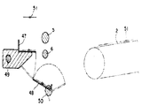
제1도는 본 발명에 의한 제품 반송장치를 나타내는 측면도.1 is a side view showing a product conveying apparatus according to the present invention.
제2도는 제1도 장치의 요부(要部)를 확대하여 나타낸 측면도.FIG. 2 is an enlarged side view of the main portion of the first FIG. Device.
제3도는 제2도에 도시된 장치 요부의 평면도.3 is a plan view of the main portion of the apparatus shown in FIG.
제4도는 제2도의 B-B선 단면도.4 is a cross-sectional view taken along the line B-B in FIG.
제5도는 유도 그립퍼가 개방된 상태에서의 제4도의 C-C선 단면도.5 is a cross-sectional view taken along the line C-C in FIG. 4 with the induction gripper open.
제6도는 유도 그립퍼가 폐쇄된 상태에서의 제4도의 C-C선 단면도.6 is a sectional view taken along the line C-C in FIG. 4 with the induction gripper closed.
제7도는 가공장치로 부터 송출된 제품을 유도 그립퍼로 파지하였을 때의 상태를 나타내는 사시도.7 is a perspective view showing a state when a product sent out from a processing apparatus is gripped with an induction gripper.
제8도 내지 제10도는 제품이 인출되어 유도 그립퍼로 부터 빠져나올 때까지의 공정을 나타내는 측면도.8 to 10 are side views showing the process until the product is withdrawn and exited from the induction gripper.
제11도는 제품을 유도 그립퍼로 부터 낙하 바아에 의해 낙하시킬 때의 상태를 나타내는 사시도.11 is a perspective view showing a state when the product is dropped by the drop bar from the guide gripper.
제12도는 유도 그립퍼로 부터 낙하된 제품을 콘베이어로 이송하는 상태를 나타내는 제1도의 A-A선 단면도.12 is a cross-sectional view taken along the line A-A in FIG.
제13도는 종래의 반송장치에 의한 제품에 있어서 유도 그립퍼가 전진할 때의 상태를 나타내는 측면도.Fig. 13 is a side view showing a state when the guide gripper advances in a product by a conventional conveying apparatus.
제14도는 종래의 반송장치에 의한 제품이 콘베이어 상에 재치된 상태를 나타내는 평면도이다.14 is a plan view showing a state where a product by a conventional conveying apparatus is placed on a conveyor.
* 도면의 주요부분에 대한 부호의 설명* Explanation of symbols for main parts of the drawings
(1) : 가공장치 (2) : 콘베이어(1): processing equipment (2): conveyor
(3) : 프레임 (4)(5)(6) : 지지간(3): frame (4) (5) (6): support
(51) : 제품 (7) : 제품유도장치(51): Product (7): Product Induction Device
(10) : 가동베이스 (11) : 협지 로울러10: movable base 11: clamping roller
(12) : 아암 (12) : 그립퍼 홀더12: Arm 12: Gripper Holder
(14) : 유도 그립퍼 (15) : 상편(上片)(14): induction gripper (15): upper piece
(16) : 하편(下片) (17) : 지축(16): lower part (17): support shaft
(18) : 구동 벨트 (19) : 구동장치(18): drive belt (19): drive
(20)(21) : 리미트 스위치 (8) : 제품낙하장치(20) (21): Limit switch (8): Product dropping device
(22) : 고정 베이스 (23) : 낙하 바아(bar)(22): fixed base (23): drop bar (bar)
(24) : 스프링 (25) : 스톱퍼24: spring 25: stopper
(9) : 운동변환장치 (26) : 제1로울러(9): Motion converter (26): First roller
(27) : 제1캠 (28) : 레버(27): first cam (28): lever
(29) : 제2로울러 (30) : 제2캠(29): 2nd Roller (30): 2nd Cam
(31) : 추축(樞軸) (32) : 크랭크반(盤)(31): shaft (32): crank plate (盤)
(33) : 브라켓 (34) : 억지부(抑止部)(33): bracket (34): hard part
(35) : 연결간 (36) : 지간(枝杆)(35): Between Connections (36): Span
(37) : 핀 (38) : 스프링37: pin 38: spring
(39) : 잠금 너트 (40) : 폐쇄장치(39): lock nut (40): closure
(41) : 제3로울러 (42) : 가이드 바아(41): third roller 42: guide bar
(43) : 제3캠 (44) : 작동간(43): third cam (44): between operation
(45) : 벨 크랭크 (46) : 송출그립퍼(45): Bell Crank 46: Output Gripper
(47) : 제1팔레트 (48) : 제2팔레트(47): First Palette (48): Second Palette
(49) : 제1축 (50) : 제2축(49): 1st axis (50): 2nd axis
(53) : 핀 (52) : 베어링53: pin 52: bearing
본 발명은 주로 유연성이 있는 띠 모양의 물건, 예컨대 슬라이드 파스너 혹은 직성(織成) 내지 편성(編成)의 테이프 등을 제품으로 마무리하는 공정 사이에서 옮겨줄 때에 사용되는 반송장치에 관한 것이다.BACKGROUND OF THE INVENTION Field of the Invention [0001] The present invention mainly relates to a conveying apparatus for use in transferring a flexible band-like article such as a slide fastener or a woven or knitted tape to a process of finishing the product.
반송되는 제품이 슬라이드 파스너인 경우에 의하여 설명하면, 그 제조공정은 장척(長尺)의 파스너 체인(테이프의 한쪽 가장자리에 엘레멘트를 지착한 한쌍의 파스너 스트링거를 서로 교합시킨 것을 의미함)을 마무리 가공장치에 송입하여 이 마무리 가공장치에서 파스너 체인에 슬라이더나 상지구(上止具) 등을 부착하고, 소정의 길이로 절단하여 슬라이드 파스너로 마무리한 후, 마무리된 슬라이드 파스너를 콘베이어에 의하여 포장공정으로 옮겨주는 것이다. 그런데, 마무리 가공장치에 의해 마무리될 슬라이드 파스너를 콘베이어가 있는 소정의 위치까지 끌어낼 필요가 있으나 이 때 슬라이드파스너의 선단부를 그립퍼로 파지하여 그립퍼의 후퇴에 의하여 끌어내는 방법이 가장 유리하다. 왜냐하면 마무리 가공장치에 의해 송출되는 슬라이드 파스너의 선단부에 슬라이더가 있기 때문에 만약 로울러나 콘베이어상에 직접 슬라이드 파스너를 올려놓으면 슬라이더가 저항을 나타내어서 가지런히 옮겨질 확증이 얻어지지 않는다. 그러나 그립퍼로 파지하여 끌어내는 방법에도 결점이 있었다. 즉 그립퍼로 제품을 협지하여 당겨서 소정의 위치에서 그립퍼를 개방시키면 협지된 제품이 낙하하여 소정위치로 옮겨질 수 있다고 생각되지만, 실제로는 제품을 끌어낼 때의 관성이 있고, 또한 가동능률을 향상시키기 위하여 그립퍼가 이행(移行)경로의 최후단부에 도달함과 동시에 마무리가 공장치를 향하여 전진왕복하도록 설계되어 있는 것 등이 서로 겹쳐서 이와 같은 실정으로 부터 제13도에 도시된 바와 같이 제품( 5)의 선단부가 아직 그립퍼로 부터 낙하되지 않고 걸려있는 상태에서 그립퍼가 전진하며 이 전진에 의해 제품의 선단부가 절곡된 상태에서 낙하되어서 낙하하는 위치가 결정되지 않고, 그 결과 제14도에 도시된 바와 같이 그립퍼로 부터 낙하하여 콘베이어로 옮겨지는 제품의 자세가 흐뜨러지는 것이었다. 이와 같이 자세가 흐뜨러지면 다음의 제품 포장 공정에 지장을 주는 원인으로 되었다.In the case where the product to be conveyed is a slide fastener, the manufacturing process is a finishing process of a long fastener chain (meaning a pair of fastener stringers having elements fastened to one edge of the tape). It is fed into the device and attached to the fastener chain by a slider, upper strip, etc. in this finishing machine, cut to a predetermined length and finished with a slide fastener, and then the finished slide fastener is packaged by a conveyor. It is moving. By the way, it is necessary to pull out the slide fastener to be finished by the finishing apparatus to a predetermined position where the conveyor is located, but at this time, the tip of the slide fastener is gripped by the gripper to draw it out by the retraction of the gripper. Because there is a slider at the tip of the slide fastener sent out by the finishing machine, if the slide fastener is placed directly on the roller or conveyor, the slider shows resistance and no confirmation is obtained. But there was also a flaw in how to grip and pull with the gripper. In other words, if the gripper is held by the gripper and pulled to open the gripper at a predetermined position, the clamped product may fall and move to the predetermined position, but in reality, there is an inertia when pulling the product, and in order to improve operation efficiency. The gripper reaches the end of the transition path and at the same time the finish is designed to move forward and back toward the factory, such that the tip of the product 5 is overlapped with each other as shown in FIG. Is not yet dropped from the gripper, but the gripper is advanced while it is hung and the position where the tip of the product falls in the bent state and falls is not determined. As a result, as shown in FIG. The attitude of the product falling from the conveyor to the conveyor was disturbed. If the posture was distracted in this manner, it was a cause for disturbing the next product packaging process.
따라서 본 발명의 목적은 제품을 가공장치로부터 그립퍼에 의하여 끌어내어 소정의 위치로 확실하게 정상적인 자세로 낙하시켜서 콘베이어상에 제품을 가지런히 옮겨주는 것, 그리고 반송능력을 향상시키는 것을 특히 고려하여 구성한 제품 반송장치를 제공하려는 것이다. 본 발명에 의한 장치의 특징은 그립퍼가 설비된 제품 유도장치를 가공장치로 부터 제품을 유출(誘出)시키려는 소정의 위치까지의 구간내에서 왕복운동이 가능하게 설치한 것, 제품을 유출시키려는 소정 위치의 상방에 상하 운동하는 낙하 바아가 설비된 제품 낙하장치를 설치한 것, 그리고 제품유도장치의 후퇴운동에 의하여 제품 유도장치의 그립퍼를 개방시키고 또한 상기 낙하 바아를 하강시키는 운동 변환장치를 설치한 것에 의해 상술한 바와 같은 목적을 달성하는 것이다.Therefore, an object of the present invention is to take out the product by the gripper from the processing device and drop it to the predetermined position reliably in a normal position so that the product can be arranged on the conveyor, and the conveying ability is particularly considered. It is to provide a conveying device. A feature of the device according to the present invention is that the product guide device equipped with the gripper is capable of reciprocating in a section up to a predetermined position where the product is to be discharged from the processing device. A product drop device equipped with a drop bar for vertically moving up and down positions, and a motion converter for opening the gripper of the product guide device by a retraction of the product induction device and installing a motion converter for lowering the drop bar; This achieves the above object.
이상과 같은 본 발명의 구성은 도시된 실시예에 의하여 이해될 수 있다.The configuration of the present invention as described above can be understood by the illustrated embodiment.
제1도는 본 발명의 장치를 가공장치(1)와 콘베이어(2) 사이의 관계로 나타낸 것이며, 제2도와 제3도는 본 발명 장치의 요부(要部)를 나타내고 있다. 특히 제1도에 의하여 명시된 바와 같이, 도면의 좌측에 도시된 슬라이드 파스너를 마무리시키는 가공장치(1)의 프레임(3)으로부터 3개의 지지간(4)(5)(6)을 상하로 평행하게 돌설하고, 중단과 하단의 지지간(5)(6)에 제품 유도장치(7)를 돌설하며, 상단의 지지간(4)에 제품 낙하장지(8)를 설치하였고, 제품 유도장치(7)와 제품 낙장하치(8)에 걸쳐서운동 변환장치(9)를 설치한 것이다.FIG. 1 shows the apparatus of the present invention in the relation between the processing apparatus 1 and the
제품 유도장치(7)는 중단의 지지간(5)에 감장된 가동 베이스(可動 base)(10)에 하단의 지지간(6)을 끼운 한쌍의 협지로울러(11)(11)를 설치하고, 가동베이스(10)를 중단 지지간(5)을 따라 회동함이 없이 전후로 접동(摺動)하도록 설치하였다. 이 가동 베이스(10)로 부터 돌출한 아암(12)에 그립퍼 홀더(13)를 고착하고, 이 홀더(13)가 가공장치(1)와 대향하는 쪽의 선단부에 좌우 한쌍의 유도 그립퍼(14)(14)를 서로 간격을 두어 돌설하였다.The product guide device 7 is provided with a pair of narrowing rollers 11 and 11 in which a lower support stem 6 is inserted into a movable base 10 wound around the support stem 5 of the suspension. The movable base 10 was installed so that the movable base 10 could slide back and forth without rotating along the suspension support section 5. The
유도그립퍼(14)(14)는 가공장치(1)에 인접한 제1위치와 제1위치에서 멀리 떨어진 제2위치 사이를 왕복운동할 수 있고, 제1위치에서 그립퍼(14)(14)를 닫고 제2위치에서 그립퍼(14)(14)를 개방하도록 그립퍼(14)(14) 위에서 작용하는 장치가 후술된다. 각각의 유도 그립퍼(14)(14)의 상편(上片)(15)(15)은 그립퍼홀더(13)로 부터 일체로 돌출하며, 하편(下片)(16)(16)은 그립퍼 홀더(13)에 설치된 지축(支軸)(17)을 중심으로 하여 상하로 요동가능하게 추지되어 있다. 또한 가동 베이스(10)를 왕복 구동시키기 위하여, 중단의 지지간(5)의 측방에 가설한 구동 벨트(18)와 가동베이스(10)를 연결하고, 구동 벨트(18)를 제1도에 도시된 구동장치(19)에 의해 정전(正轉)과 역전(逆轉)을 교대로 행하게 하여 가동베이스(10)를 왕복 운동시키는 것이다.The
또한 가동 베이스(10)의 접동범위는 상단 지지간(4)의 전후에 설치된 리미트 스위치(20)(21)에 의해 제어된다.In addition, the sliding range of the movable base 10 is controlled by the limit switches 20 and 21 provided before and after the upper end support 4.
제품 낙하장치(8)는 상기 제품 유도장치(7)의 그립퍼(14)(14)가 가공장치(1)쪽으로 부터 후퇴하여 중단의 지지간(5)의 종단부에 있을 때, 가동베이스(10)의 근방과 대응하여 위치하는 상단의 지지간(4)에 고정베이스(22)를 감착하고, 고정베이스(22)에 파형(波形)으로 굴곡된 낙하 바아(23)를 핀(53)을 중심으로 하여 상하로 요동가능하게 추착하고, 낙하 바아(23)의 선단부에 설치된 스프링(24)으로 낙하 바아(23)가 상방으로 회동하도록 부세함과 동시에, 볼트에 의한 스톱퍼(25)로 소정 높이 이상으로의 회동을 저지하였으며, 또한 낙하바아(23)는 제품 유도장치(7)의 양측 그립퍼(14)(14) 사이로 하강하도록 배설되어 있다. 그리고, 고정베이스(22)는 지지간(4)을 따라서 전후 방향으로 이동조절될 수 있도록 되어 있다.The product dropping device 8 is movable base 10 when the
운동변환장치(9)는 제품 유도장치(7)의 후퇴운동, 즉 직선운동을 2 가지 계통의 요동운동으로 변환시키는 것으로서, 그중 한가지 계통은 낙하 바아(23)의 주지점으로 부터 후방으로 연장된 후단부에 제1로울러(26)를 설치하고, 그립퍼홀더(13)의 후단부 상면에 후단으로 부터 전방으로 점차 높아지도로 경사진 면을가진 제1캠(27)을 형성하여, 제1로울러(26)와 제1캠(27)에 의하여 낙하 바아(23)를 하강시킨 후, 낙하 바아(23)에 설치된 스프링(24)에 의하여 복귀운동, 즉 상승시키는 것이다. 다른 하나의 계통은 그립퍼 홀더(13)에 대략 3각형의 판체(板體)로 이루어진 레버(28)를 그 하나의 정점부(31)에서 추지하고, 다른 각 정점부에 제2로울러(29) 및 제3로울러(41)를 설치하고, 제품 낙하장치(8)의 고정 베이스(22)에 판체의 하면이 전단으로 부터 후방으로 점차 낮아지게 되어 있는 경사면을 가진 제2캠(30)을 설치한 것이다. 그리고 레버(28)를 추지하는 추축(樞軸)(31)에 제4도 내지 제6도에 도시된 바와 같이 원반의 외주(外周)의 일부를 산모양으로 절결한 절결부(32a)(32b)를 크랭크 반(crank 盤)(32)을 감착하고, 베어링(52)을 통해 추축(31)을 지지하는 브라켓(33)의 상부에 크랭크반(32)의 회전각도를 규제하는 억지부(抑止部)(34)를 형성하여서, 크랭크반(32)을 그 절결부(32a)(32b)와 억지부(34)에 의하여 소정의 각도 범위내에서 좌우로 요동하도록 설치한다.The motion converter 9 converts the retraction motion, ie the linear motion, of the product induction device 7 into two types of swing motions, one of which extends backward from the point of the
즉, 레버(28)는 유도 그립퍼(14)(14)가 닫히고 절결부(32a)가 억지부(34)에 걸리게 되는 폐쇄위치와 유도그립퍼(14)(14)가 열리고 절결부(32b)가 억지부(34)에 걸리게 되는 개방위치 사이를 요동할 수 있다.That is, the lever 28 has a closed position in which the
절결부(32a)(32b)와 억지부(34)는 레버(28)의 각 운동정도를 제한하여 줄뿐만 아니라, 그립퍼(14)(14)가 전술한 제1위치에서 제2위치로 주행하는 동안에는 폐쇄위치에 그리고 제2위치에서 제1위치로 되돌아오는 동안에는 개방위치에 상기 그립퍼(14)(14)를 유지하여 주는 기능을 한다. 베이스(10)의 주행중에 제5도 및 제6도에 도시된대로 절결부(32a, 32b)가 억지부(34)와 확실한 계합을 유지할 수 있게 하기 위하여 오우버 센터(over center) 스프링(60)이 제3로울러(41)와 베이스(10) 상의 돌출봉 사이에 걸쳐 인장설치되어 있다(제2도 및 제3도 참조). 또한 상기 레버(28)는 제2도에 명시된 바와 같이 제2로울러(29)가 추축(31)의거의 바로 위에 위치하고 제3로울러(41)가 추축(31)으로 부터 비스듬히 후방으로 위치하도록 설치되어 있다.
그리고 상기 크랭크반(32)의 추축(31)으로 부터 앞쪽의 편심위치에 연결간(35)을 추지하고, 연결간(35)의 선단부를 유도 그립퍼(14)의 하편(下片)(16)에 간접적으로 연결하였다. 즉, 제2도와 제11도에 도시된 바와 같이 연결간(35)의 선단부에 지간(枝杆)(36)을 T자형으로 고착하고, 지간(36)의 좌우 양단부에 접동이 자유롭게 관통된 각각의 가이드핀(37)(37)을 대향하는 유도 그립퍼(14)(14)의 하편(16)(16)에 고착하고, 또한 가이드 핀(37)(37)의 하편(16)(16)과 지간(36) 사이에 압축스프링(38)을 끼운 것이다. 그리고 가이드 핀(37)(37)의 접동범위를 조절할 수 있도록 두부(頭部)에 잠금 너트(39)가 나함(螺合)되어 있어서, 제2도에 도시된 바와 같이 레버(28)가 기립하여 제2로울러(29)가 추축(31)의 거의 바로 위에 위치하는 상태에서는 크랭크반(32)이 제5도에서와 같이 시계방향 회전의 극한에있게 되어서 유도그립퍼(14)(14)를 폐쇄하고 있다. 그러나 레버(28)를 상기의 상태로 부터 전방을 향하여(도면에서는 반시계방향 회전) 회전시키면, 크랭크반(32)은 반시계방향 회전하여 제6도에서와 같이 그 극한으로 까지 다다른다. 이때에는 연결간(35)을 후방으로 밀어붙이기 때문에 유도 그립퍼(14)(14)가 개방된다. 또 다시 레버(28)를 기립시키면 연결간(35)이 크랭크기구에 의해 전진하기 때문에 압축 스프링(38)이 압축되고, 이 압축력에 의하여 상편(15)을 폐쇄하는 방향으로 회등하며, 그후 적당한 압력에 의해 유도 그립퍼(14)(14)가 폐쇄상태를 유지하는 것이다.Then, the connecting
이때, 개방된 유도 그립퍼(14)(15)를 또 다시 폐쇄하는 것은 상기 레버(28)에 설치된 제3로울러(41)의 폐쇄장치(40)에 의하여 행하여진다. 폐쇄장치(40)는 제1도에 도시된 바와 같이 가공장치(1)의 프레임(3)에 설치된 것으로서, 프레임(3)의 각 지지간(4)(5)(6)이 돌출된 쪽에 지지간(4)(5)(6)과 평행한 가이드바아(42)를 설치하고, 이 바아(42)에 상기 제3로울러(41)와 대향하는 제3캠(43)을 감장하며, 가공장치(1)로부터 기립하여 돌설되어 타이밍을 두고 상하로 운동하는 작동간(44)과 상기 제3캠(43)을 벨 크랭크(bell crank)(45)를 통해 연결하였다. 제3캠(43)은 판체로 이루어지며, 그 제3로울러(41)와 서로 대향하는 단면(端面)을 하방으로 부터 상방으로 점차 돌출시키는 경사면이 형성되어 있다.At this time, closing the
제1도에 도시된 가공장치(1)는 상술한 바와 같이 슬라이드 파스너를 마무리하는 장치로서, 가공된 제품(51)을 장치의 출구까지 제7도에 도시된 것처럼 다수의 송출 그립퍼(46)로 송출하고, 유도그립퍼(14)(14)로 제품(51)의 단부 양측을 간격을 두고 파지한 후에 송출 그립퍼(46)를 해제시키는 것이며, 따라서 유도그립퍼(14)(14)가 폐쇄되는 타이밍은 제품(51)이 가공장치(1)의 출구로 송출된 때에 행하여지는 것이다.The processing apparatus 1 shown in FIG. 1 is an apparatus for finishing the slide fastener as described above, and the processed
한편, 가공장치(1)로 부터 소정의 위치까지 인출되어 낙하할 때 직접 콘베이어(2)상으로 낙하되는 것이 아니라, 제12도에 도시된 바와 같이 제1팔레트(palette)(47)와 제2팔레트(48)를 거쳐서 콘베이어(2) 상에 얹혀지게 되는 것으로서, 하단의 지지간(6)으로 부터 하방의 한쪽으로 붙어서 지지간(6)과 평행하게 가설된 제1축(49)에 제1팔레트(47)를 고착하고, 이것으로 유도그립퍼(14)(14)로 부터 낙하되는 제품(51)을 직접 수용하며, 또한 하단의 지지간(6)의 하방에 그리고 제1축(49)보다도 하부에 마찬가지로 평행하게 가설된 제2축(50)에 제2팔레트(48)를 고착하고, 제1팔레트(47)의 경사에 따라서 미끄러져 내려오는 제품(51)을 제2팔레트(48)로 수용하며, 또한 제2팔레트(48)가 경사하여 제품(51)을 콘베이어(2) 상으로 옮겨주는 것이다. 그리고 콘베이어(2)는 각 지지간(4)(5)(6)과 직교하도록 설치되어 있다. 또한 상술한 바와 같이 상하로 팔레트(47)(48)를 설치한 이유는, 유도 그립퍼(14)(14)로 부터 낙하한 제품(51)을 그 표면과 이면을 뒤집어서 콘베이어(2)에 공급하기 위한 것이다. 따라서 뒤집어줄 필요가 없으면 제1팔레트(47)만을 설치하면 된다.On the other hand, when it is withdrawn from the processing apparatus 1 to a predetermined position and falls, it does not fall directly on the
본 발명은 이상과 같은 구조를 갖는 것으로서, 가공장치(1)로 부터 송출된 제품(51)을 소정의 위치까지 유도하여 콘베이어(2)상에 올려놓는 동안의 작동은 제7도 내지 제12도에 도시된 바와 같이 제품(51)의 선단부에서의 양측부를 간격을 두고 유도 그립퍼(14)(14)로 파지하고, 그 상태에서 그대로 후퇴시켜 제품(51)을 가공장치(1)로 부터 인출한다. 그리고 유도 그립퍼(14)(14)는 제10도에 도시된 바와 같이 후퇴하는 종단부에 이르렀을 때 또 다시 가공장치(1)를 향하여 전진한다. 이때 유도 그립퍼(14)(14)가 제품(51)을 파지하여 종단부에 가까와짐에 따라서, 제8도에 도시된 바와 같이 제품 유도장치(7)가 후퇴하는 운동에 의해 운동 변환장치(9)의 제1캠(27)과 제1로울러(26)가 계합하여 제품 낙하장치(8)의 낙하 바아(23)가 하강하기 시작하며, 유도그립퍼(14)(14)가 또한 후퇴함과 동시에 운동 변환장치(9)의 제2로울러(29)와 제2캠(30)과의 계합에 의해 제9도에 도시된 바와 같이 유도 그립퍼(14)(14)가 개방된다.The present invention has the structure as described above, the operation of the
이때, 낙하 바아(23)가 제11도에서와 같이 양측 유도 그립퍼(14)(14)의 사이로 하강을 계속하는 결과, 낙하 바아(23)의 선단이 제품(51)의 양측 유도그립퍼(14)(14)로 잡혀진 부분 사이의 중간부, 즉 제품(51)이 도시된 바와 같이 슬라이드 파스너라면 중간부에 있는 슬라이더(S)에 맞닿아서 제품(51)이 전방으로 이동하려고 하는 관성을 정지시킴과 동시에 낙하 바아(23)는 다시 하강하기 때문에, 제품(51)이 하방으로 눌려진다. 이와같이 하여 유도 그립퍼(14)(14)가 후퇴한계의 종단부에 도달하였을 때에는, 제품(51)이 유도 그립퍼(14)(14)로 부터 완전히 탈락되는 것이다. 그후 유도그립퍼(14)(14)는 전진하고, 낙하 바아(23)가 스프링(24)의 탄발력에 의하여 상승하는 것이다.At this time, as the
또한 낙하된 제품(51)은 실시예의 경우에서는 제12도에 도시된 바와 같이 직접 제1팔레트(47)에 올려놓여지고, 제1팔레트(47)가 회동하여 제품(51)이 제2팔레트(48)로 옮겨지고, 제2팔레트(48)가 전도(轉倒)함으로써 제품(51)이 뒤집혀져 콘베이어(2) 상에 올려져서 다음 공정으로 반송된다. 한편, 전진하는 유도그립퍼(14)(14)는 개방되어 있어 또 다시 가공장치(1)로 부터 송출되는 제품(51)을 파지하며, 유도 그립퍼(14)(14)는 제3캠(43)과 제3로울러(41)의 계합에 의하여 폐쇄된다.Also, in the case of the embodiment, the dropped
이상과 같이, 본 발명에 의한 제품 반송장치는 가공장치로 부터 제품을 제품 유도장치의 유도 그립퍼로 파지하여 인출하고, 제품을 인출한 소정 위치의 상방에 상하로 운동하는 낙하 바아가 설비된 제품 낙하장치를 설치하고, 또한 제품 유도장치가 후퇴하는 운동에 의하여 낙하 바아를 하강시키고 유도 그립퍼를 개방하는 운동 변환장치를 제품 유도장치와 제품 낙하장치에 걸쳐서 설치하고, 제품을 파지한 유도 그립퍼가 후퇴하여 제품을 낙하시킬 소정 위치의 근처에 도달했을 때 낙하 바아가 하강하기 시작하여 유도 그립퍼가 개방되기 때문에, 파지되어 있는 제품이 낙하 바아에 의하여 정지됨과 동시에 제품이 강제적으로 하방을 향하여 눌려지게 되고, 그 결과 제품은 유도 그립퍼로 부터 확실히 벗겨짐과 동시에, 결정된 위치로 절곡되거나 경사짐이 없이 정상적인 자세로 다음 공정으로 반송되는 것이다.As described above, the product conveying apparatus according to the present invention is a product drop equipped with a drop bar for holding the product from the processing device with the induction gripper of the product induction device to take out, and to move up and down above the predetermined position where the product is drawn When the device is installed, and the motion induction device which lowers the drop bar and opens the induction gripper by the retraction movement of the product induction device is installed over the product induction device and the product drop device, the induction gripper holding the product retreats. When the drop bar starts to descend when the product reaches the predetermined position to drop the product and the induction gripper is opened, the gripped product is stopped by the drop bar and the product is forcibly pressed downward. The resulting product is reliably peeled off the induction gripper and bent or inclined to the determined position This will be conveyed to the next step in a normal attitude without.
Claims (1)
Applications Claiming Priority (3)
| Application Number | Priority Date | Filing Date | Title |
|---|---|---|---|
| JP???56-19976 | 1981-02-12 | ||
| JP56019976A JPS57132983A (en) | 1981-02-12 | 1981-02-12 | Conveyor for product |
| JP19976 | 1998-01-30 |
Publications (2)
| Publication Number | Publication Date |
|---|---|
| KR830008911A KR830008911A (en) | 1983-12-16 |
| KR850001426B1 true KR850001426B1 (en) | 1985-10-02 |
Family
ID=12014212
Family Applications (1)
| Application Number | Title | Priority Date | Filing Date |
|---|---|---|---|
| KR8200582A KR850001426B1 (en) | 1981-02-12 | 1982-02-11 | Feed mechanism apparatus |
Country Status (12)
| Country | Link |
|---|---|
| US (1) | US4460083A (en) |
| EP (1) | EP0058881B1 (en) |
| JP (1) | JPS57132983A (en) |
| KR (1) | KR850001426B1 (en) |
| AU (1) | AU527162B2 (en) |
| BR (1) | BR8200797A (en) |
| CA (1) | CA1188335A (en) |
| DE (2) | DE3262244D1 (en) |
| ES (1) | ES509544A0 (en) |
| GB (1) | GB2093788B (en) |
| HK (1) | HK62888A (en) |
| MY (1) | MY8700424A (en) |
Families Citing this family (10)
| Publication number | Priority date | Publication date | Assignee | Title |
|---|---|---|---|---|
| IT1167360B (en) * | 1983-05-20 | 1987-05-13 | Siasprint Srl | CLAMP DEVICE FOR TRANSPORT AND REGISTRATION OF PANELS OR SHEETS TO BE PRINTED ON MACHINES FOR SCREEN PRINTING IN ONE OR MORE COLORS |
| JPS60114204A (en) * | 1983-11-26 | 1985-06-20 | ワイケイケイ株式会社 | Gripper apparatus in finish processing of slide fastener |
| JPS60147381U (en) * | 1984-03-09 | 1985-09-30 | ワイケイケイ株式会社 | Sewing product traction device for sewing machine |
| JPS6190604A (en) * | 1984-10-09 | 1986-05-08 | ワイケイケイ株式会社 | Apparatus for discharging slide fastener |
| US4715774A (en) * | 1985-12-23 | 1987-12-29 | Peddinghaus Corporation | Workpiece advancing apparatus |
| US5480133A (en) * | 1994-05-05 | 1996-01-02 | A.W.T. World Trade, Inc. | Adjustable sheet take-off mechanism for a screen printing press |
| US5816771A (en) * | 1995-03-09 | 1998-10-06 | Electro-Mechancis Corporation | Gripper arm assembly |
| CN103482408B (en) * | 2012-06-11 | 2016-08-03 | 顾严煌 | A kind of cable construction transfer vehicle |
| CN103668378B (en) * | 2012-08-31 | 2016-04-13 | 鸿富锦精密工业(深圳)有限公司 | Charging equipment |
| CN106865336B (en) * | 2017-04-18 | 2023-02-28 | 山东威高血液净化制品股份有限公司 | Linear filament winding method and device for hollow fiber membrane |
Family Cites Families (15)
| Publication number | Priority date | Publication date | Assignee | Title |
|---|---|---|---|---|
| US1854775A (en) * | 1929-11-12 | 1932-04-19 | Wichmann Reginald | Sheet depositing device |
| US2276269A (en) * | 1940-09-09 | 1942-03-17 | Miehle Printing Press & Mfg | Sheet delivery mechanism |
| US2754908A (en) * | 1951-05-25 | 1956-07-17 | Ralph A Proud | Machine for cutting slide fastener strips |
| CH327311A (en) * | 1954-12-09 | 1958-01-31 | Gaston Sauvion Rene | Sheet receiving device for printing machine |
| US2831684A (en) * | 1955-05-31 | 1958-04-22 | Eastman Kodak Co | Cut-sheet stacking and take-away mechanism |
| DE1610456A1 (en) * | 1964-03-31 | 1970-11-12 | Zentrale Entwicklung Konstrukt | Method and device for assembling zippers |
| US3430949A (en) * | 1967-09-18 | 1969-03-04 | Usm Corp | Fabric handling machines |
| US3625506A (en) * | 1969-11-28 | 1971-12-07 | Ivanhoe Research Corp | Method and apparatus for differentiating the top fibrous workpiece from a stack of fibrous workpieces and for separating the differentiated workpiece from the stack |
| US3747920A (en) * | 1971-04-14 | 1973-07-24 | Warner Swasey Co | Unloader assembly |
| DE2154548A1 (en) * | 1971-11-03 | 1973-05-10 | Opti Holding Ag | DEVICE FOR SEPARATING ENDLESS ZIPPER CHAIN |
| FR2349523A1 (en) * | 1976-04-26 | 1977-11-25 | Anvar | AUTOMATIC PLANT FOR GRIPPING PARTS, ESPECIALLY TEXTILE PARTS |
| GB2007196B (en) * | 1977-11-04 | 1982-02-24 | Valton Sa | Device for gripping and displaying knitting or woven articles |
| US4263712A (en) * | 1978-12-07 | 1981-04-28 | Dale Products, Inc. | Battery plate wrapping machine and method |
| JPS5941721B2 (en) * | 1978-12-29 | 1984-10-09 | ワイケイケイ株式会社 | Manufacturing method and device for slide fastener with releasable fitting |
| JPS5933367B2 (en) * | 1979-03-05 | 1984-08-15 | ワイケイケイ株式会社 | Intermittent fastener chain combination device for slide fasteners with release tool |
-
1981
- 1981-02-12 JP JP56019976A patent/JPS57132983A/en active Granted
-
1982
- 1982-02-02 AU AU79998/82A patent/AU527162B2/en not_active Ceased
- 1982-02-04 GB GB8203251A patent/GB2093788B/en not_active Expired
- 1982-02-10 DE DE8282100974T patent/DE3262244D1/en not_active Expired
- 1982-02-10 EP EP82100974A patent/EP0058881B1/en not_active Expired
- 1982-02-10 DE DE198282100974T patent/DE58881T1/en active Pending
- 1982-02-11 US US06/347,932 patent/US4460083A/en not_active Expired - Fee Related
- 1982-02-11 KR KR8200582A patent/KR850001426B1/en active
- 1982-02-11 CA CA000396046A patent/CA1188335A/en not_active Expired
- 1982-02-12 ES ES509544A patent/ES509544A0/en active Granted
- 1982-02-15 BR BR8200797A patent/BR8200797A/en not_active IP Right Cessation
-
1987
- 1987-12-30 MY MY424/87A patent/MY8700424A/en unknown
-
1988
- 1988-08-18 HK HK628/88A patent/HK62888A/en unknown
Also Published As
| Publication number | Publication date |
|---|---|
| DE58881T1 (en) | 1983-03-03 |
| GB2093788B (en) | 1985-01-30 |
| EP0058881B1 (en) | 1985-02-13 |
| US4460083A (en) | 1984-07-17 |
| ES8301174A1 (en) | 1982-12-16 |
| HK62888A (en) | 1988-08-26 |
| GB2093788A (en) | 1982-09-08 |
| KR830008911A (en) | 1983-12-16 |
| BR8200797A (en) | 1982-12-21 |
| ES509544A0 (en) | 1982-12-16 |
| AU7999882A (en) | 1982-11-04 |
| JPS615876B2 (en) | 1986-02-21 |
| CA1188335A (en) | 1985-06-04 |
| JPS57132983A (en) | 1982-08-17 |
| MY8700424A (en) | 1987-12-31 |
| EP0058881A1 (en) | 1982-09-01 |
| DE3262244D1 (en) | 1985-03-28 |
| AU527162B2 (en) | 1983-02-17 |
Similar Documents
| Publication | Publication Date | Title |
|---|---|---|
| KR850001426B1 (en) | Feed mechanism apparatus | |
| US3955667A (en) | Endless conveyor with gripping elements | |
| US4976603A (en) | Pivoting workpiece removal device | |
| US4106260A (en) | Article folding and packaging system | |
| US7255638B2 (en) | Handling system for sausages | |
| US3930572A (en) | Apparatus for separating a series of objects | |
| KR890003511Y1 (en) | Apparatus for manufacturing slide fasteners | |
| US4450948A (en) | Apparatus for supplying headed parts | |
| US5423649A (en) | Apparatus for cutting and removing package material | |
| US4615288A (en) | Mechanism for drawing an elongated sewn product from a sewing machine | |
| US4462201A (en) | Method and apparatus for discharging objects from holders | |
| US4033088A (en) | Method of and apparatus for packaging poultry specimens | |
| US4262944A (en) | Broccoli bunching and tying machine | |
| KR900006026B1 (en) | Parts applicator for slide fastener | |
| EP0179335B1 (en) | Slide-fastener discharging apparatus | |
| US4592462A (en) | Carousel type feeder for carton blanks | |
| US4439262A (en) | Labeling station for articles like bottles | |
| US4822448A (en) | Fabric band making and label applying machine | |
| KR870001355Y1 (en) | Apparatus for holding boxes in attachment of same to separable slide fastener chain | |
| CN219628977U (en) | Zipper puller penetrating machine for multi-pendant puller | |
| CN220255868U (en) | Double-hanging-piece slider zipper machine | |
| US3175673A (en) | Article handling and advancing mechanism | |
| CN116058573A (en) | Zipper puller penetrating machine for multi-pendant puller | |
| JP3777679B2 (en) | Box front flap opening device | |
| KR100414993B1 (en) | Device for simultaneously forming upper jig and lower jig of slide fastener |