KR20240042658A - Exterior vehicle door handles, vehicle door assemblies and vehicles - Google Patents
Exterior vehicle door handles, vehicle door assemblies and vehicles Download PDFInfo
- Publication number
- KR20240042658A KR20240042658A KR1020247008337A KR20247008337A KR20240042658A KR 20240042658 A KR20240042658 A KR 20240042658A KR 1020247008337 A KR1020247008337 A KR 1020247008337A KR 20247008337 A KR20247008337 A KR 20247008337A KR 20240042658 A KR20240042658 A KR 20240042658A
- Authority
- KR
- South Korea
- Prior art keywords
- vehicle door
- handle
- handle grip
- exterior
- grip
- Prior art date
- Legal status (The legal status is an assumption and is not a legal conclusion. Google has not performed a legal analysis and makes no representation as to the accuracy of the status listed.)
- Granted
Links
Images


Classifications
-
- E—FIXED CONSTRUCTIONS
- E05—LOCKS; KEYS; WINDOW OR DOOR FITTINGS; SAFES
- E05B—LOCKS; ACCESSORIES THEREFOR; HANDCUFFS
- E05B85/00—Details of vehicle locks not provided for in groups E05B77/00 - E05B83/00
- E05B85/10—Handles
-
- E—FIXED CONSTRUCTIONS
- E05—LOCKS; KEYS; WINDOW OR DOOR FITTINGS; SAFES
- E05B—LOCKS; ACCESSORIES THEREFOR; HANDCUFFS
- E05B85/00—Details of vehicle locks not provided for in groups E05B77/00 - E05B83/00
- E05B85/10—Handles
- E05B85/103—Handles creating a completely closed wing surface
-
- B—PERFORMING OPERATIONS; TRANSPORTING
- B60—VEHICLES IN GENERAL
- B60J—WINDOWS, WINDSCREENS, NON-FIXED ROOFS, DOORS, OR SIMILAR DEVICES FOR VEHICLES; REMOVABLE EXTERNAL PROTECTIVE COVERINGS SPECIALLY ADAPTED FOR VEHICLES
- B60J5/00—Doors
- B60J5/04—Doors arranged at the vehicle sides
- B60J5/0412—Lower door structure
- B60J5/0415—Outer panel
-
- B—PERFORMING OPERATIONS; TRANSPORTING
- B60—VEHICLES IN GENERAL
- B60J—WINDOWS, WINDSCREENS, NON-FIXED ROOFS, DOORS, OR SIMILAR DEVICES FOR VEHICLES; REMOVABLE EXTERNAL PROTECTIVE COVERINGS SPECIALLY ADAPTED FOR VEHICLES
- B60J5/00—Doors
- B60J5/04—Doors arranged at the vehicle sides
- B60J5/0412—Lower door structure
- B60J5/0416—Assembly panels to be installed in doors as a module with components, e.g. lock or window lifter, attached thereto
-
- E—FIXED CONSTRUCTIONS
- E05—LOCKS; KEYS; WINDOW OR DOOR FITTINGS; SAFES
- E05B—LOCKS; ACCESSORIES THEREFOR; HANDCUFFS
- E05B79/00—Mounting or connecting vehicle locks or parts thereof
- E05B79/02—Mounting of vehicle locks or parts thereof
- E05B79/06—Mounting of handles, e.g. to the wing or to the lock
-
- E—FIXED CONSTRUCTIONS
- E05—LOCKS; KEYS; WINDOW OR DOOR FITTINGS; SAFES
- E05B—LOCKS; ACCESSORIES THEREFOR; HANDCUFFS
- E05B81/00—Power-actuated vehicle locks
- E05B81/02—Power-actuated vehicle locks characterised by the type of actuators used
- E05B81/04—Electrical
- E05B81/06—Electrical using rotary motors
-
- E—FIXED CONSTRUCTIONS
- E05—LOCKS; KEYS; WINDOW OR DOOR FITTINGS; SAFES
- E05B—LOCKS; ACCESSORIES THEREFOR; HANDCUFFS
- E05B81/00—Power-actuated vehicle locks
- E05B81/12—Power-actuated vehicle locks characterised by the function or purpose of the powered actuators
-
- E—FIXED CONSTRUCTIONS
- E05—LOCKS; KEYS; WINDOW OR DOOR FITTINGS; SAFES
- E05B—LOCKS; ACCESSORIES THEREFOR; HANDCUFFS
- E05B81/00—Power-actuated vehicle locks
- E05B81/54—Electrical circuits
- E05B81/64—Monitoring or sensing, e.g. by using switches or sensors
- E05B81/76—Detection of handle operation; Detection of a user approaching a handle; Electrical switching actions performed by door handles
-
- E—FIXED CONSTRUCTIONS
- E05—LOCKS; KEYS; WINDOW OR DOOR FITTINGS; SAFES
- E05B—LOCKS; ACCESSORIES THEREFOR; HANDCUFFS
- E05B85/00—Details of vehicle locks not provided for in groups E05B77/00 - E05B83/00
- E05B85/10—Handles
- E05B85/107—Pop-out handles, e.g. sliding outwardly before rotation
-
- E—FIXED CONSTRUCTIONS
- E05—LOCKS; KEYS; WINDOW OR DOOR FITTINGS; SAFES
- E05B—LOCKS; ACCESSORIES THEREFOR; HANDCUFFS
- E05B85/00—Details of vehicle locks not provided for in groups E05B77/00 - E05B83/00
- E05B85/10—Handles
- E05B85/14—Handles pivoted about an axis parallel to the wing
-
- E—FIXED CONSTRUCTIONS
- E05—LOCKS; KEYS; WINDOW OR DOOR FITTINGS; SAFES
- E05Y—INDEXING SCHEME ASSOCIATED WITH SUBCLASSES E05D AND E05F, RELATING TO CONSTRUCTION ELEMENTS, ELECTRIC CONTROL, POWER SUPPLY, POWER SIGNAL OR TRANSMISSION, USER INTERFACES, MOUNTING OR COUPLING, DETAILS, ACCESSORIES, AUXILIARY OPERATIONS NOT OTHERWISE PROVIDED FOR, APPLICATION THEREOF
- E05Y2900/00—Application of doors, windows, wings or fittings thereof
- E05Y2900/50—Application of doors, windows, wings or fittings thereof for vehicles
- E05Y2900/53—Type of wing
- E05Y2900/531—Doors
Landscapes
- Engineering & Computer Science (AREA)
- Mechanical Engineering (AREA)
- Lock And Its Accessories (AREA)
Abstract
차량 도어 조립체가 제공된 차량. 차량 도어 조립체는 외부 차량 도어 핸들을 포함하고; 외부 차량 도어 핸들은 베이스 및 핸들 그립을 포함한다. 베이스는 홈을 구비하고 차량 도어에 장착되기에 적합하다. 핸들 그립은 폐쇄 위치와 개방 위치 사이에서 베이스 상에 회전가능하게 장착되고; 핸들 그립이 폐쇄 위치에 있을 때, 핸들 그립의 외부 표면은 차량 도어의 외부 표면 밖으로 돌출하지 않고 홈을 덮고; 핸들 그립이 홈의 내부를 향해 회전함으로써 폐쇄 위치로부터 개방 위치로 회전할 때, 핸들 그립은 차량 도어의 외부 표면 밖으로 돌출하지 않고 홈이 노출된다.Vehicles provided with a vehicle door assembly. The vehicle door assembly includes an external vehicle door handle; An exterior vehicle door handle includes a base and a handle grip. The base has a groove and is suitable for mounting on a vehicle door. The handle grip is rotatably mounted on the base between a closed position and an open position; When the handle grip is in the closed position, the outer surface of the handle grip covers the groove without protruding beyond the outer surface of the vehicle door; When the handle grip rotates from the closed position to the open position by rotating toward the inside of the groove, the handle grip does not protrude beyond the outer surface of the vehicle door and the groove is exposed.
Description
관련 출원들에 대한 상호-참조Cross-reference to related applications
본 개시내용은 발명의 명칭을 "외부 차량 도어 핸들, 차량 도어 조립체 및 차량(EXTERIOR VEHICLE DOOR HANDLE, VEHICLE DOOR ASSEMBLY, AND VEHICLE)"으로하여 2021년 11월 30일자로 출원 중국 특허 출원 번호 202111451995.X에 대한 우선권을 주장한다. 위에 참조된 출원의 전체 내용은 본 명세서에 참조로서 포함된다.This disclosure is filed on November 30, 2021 with the title of the invention “EXTERIOR VEHICLE DOOR HANDLE, VEHICLE DOOR ASSEMBLY, AND VEHICLE” and Chinese Patent Application No. 202111451995.X claims priority for. The entire contents of the above-referenced applications are incorporated herein by reference.
기술분야Technology field
본 개시내용은 차량 분야에 관한 것으로, 더 구체적으로는 외부 차량 도어 핸들, 차량 도어 조립체 및 차량에 관한 것이다.This disclosure relates to the automotive field, and more specifically to exterior vehicle door handles, vehicle door assemblies, and vehicles.
관련 기술분야에서의 외부 차량 도어 핸들은 일반적으로 베이스 및 핸들 그립을 포함한다. 핸들 그립은 일반적으로 노출된 상태에 있고, 불결한 외관을 가질 뿐만 아니라, 차량 외부의 물체들에 의해 스크래치될 수 있고, 쉽게 손상된다. 따라서, 일부 외부 차량 도어 핸들들은 은폐되도록 구성된다. 잠금될 때, 외부 차량 도어 핸들의 핸들 그립은 은폐된 상태가 되는데, 즉, 핸들 그립은 차량 도어로부터 돌출되지 않는다. 그러나, 잠금해제 상태에 있을 때, 핸들 그립은 외측으로 회전하고 차량 도어의 외부 표면으로부터 돌출한다. 모터가 회전 동작을 수행하지 않을 때, 핸들 그립이 차량 도어의 외부 표면으로부터 돌출한다는 문제가 항상 있다. 노출된 상태에서의 핸들 그립은 차량의 청결성 및 고객들의 사용 경험에 영향을 줄 뿐만 아니라, 차량의 주행 바람 저항을 증가시켜서, 차량의 에너지 소비를 증가시킨다. 또한, 온도가 비교적 낮을 때, 차량 도어의 외부 표면이 결빙될 수 있으며, 이는 핸들 그립을 외측으로 회전시키는 것을 불편하게 한다.Exterior vehicle door handles in the related art typically include a base and a handle grip. Steering wheel grips are usually in an exposed state and not only have a dirty appearance, but they can also be scratched by objects outside the vehicle and are easily damaged. Accordingly, some exterior vehicle door handles are configured to be concealed. When locked, the handle grip of the exterior vehicle door handle is in a concealed state, ie the handle grip does not protrude from the vehicle door. However, when in the unlocked state, the handle grip rotates outward and protrudes from the exterior surface of the vehicle door. There is always the problem that when the motor is not performing a rotating movement, the handle grip protrudes from the outer surface of the vehicle door. Exposed handle grips not only affect the vehicle's cleanliness and customer experience, but also increase the vehicle's wind resistance, thereby increasing the vehicle's energy consumption. Additionally, when the temperature is relatively low, the outer surface of the vehicle door may freeze, making it inconvenient to rotate the handle grip outward.
본 개시내용은 관련 기술분야에 존재하는 기술적 문제점들 중 적어도 하나를 해결하는 것을 목적으로 한다. 이와 관련하여, 본 출원의 일 목적은 외부 차량 도어 핸들을 제공하는 것이다. 외부 차량 도어 핸들은 완전히 은폐될 수 있고, 정돈된 외관, 높은 사용 안전성, 편리한 회전, 낮은 바람 저항 등의 장점들을 갖는다.The present disclosure aims to solve at least one of the technical problems existing in the related art. In this regard, one object of the present application is to provide an external vehicle door handle. The external vehicle door handle can be completely concealed and has the advantages of neat appearance, high use safety, convenient rotation, and low wind resistance.
본 개시내용은 전술한 외부 차량 도어 핸들을 갖는 차량 도어 조립체를 추가로 제공한다.The present disclosure further provides a vehicle door assembly having the exterior vehicle door handle described above.
본 개시내용은 전술한 차량 도어 조립체를 갖는 차량을 추가로 제공한다.The present disclosure further provides a vehicle having the vehicle door assembly described above.
전술한 목적을 달성하기 위해, 본 개시내용의 제1 양태의 실시예에 따르면, 외부 차량 도어 핸들이 제공되며, 상기 외부 차량 도어 핸들은: 베이스 - 베이스는 핸들 공동을 구비하고 차량 도어에 장착되도록 구성됨 -; 및 핸들 그립 - 핸들 그립은 폐쇄 위치와 개방 위치 사이에서 회전가능하게 베이스 상에 장착되고, 핸들 그립이 폐쇄 위치에 있을 때, 핸들 그립의 외부 표면은 차량 도어의 외부 표면으로부터 돌출하지 않고 핸들 공동을 덮으며, 핸들 그립이 핸들 공동의 내부를 향해 회전함으로써 폐쇄 위치로부터 개방 위치로 회전할 때, 핸들 그립은 차량 도어의 외부 표면으로부터 돌출하지 않고 핸들 공동은 노출됨 - 을 포함한다.To achieve the above-described object, according to an embodiment of the first aspect of the present disclosure, an exterior vehicle door handle is provided, the exterior vehicle door handle having: a base, the base having a handle cavity and configured to be mounted on a vehicle door; configured -; and a handle grip - the handle grip is mounted on the base rotatably between a closed position and an open position, wherein when the handle grip is in the closed position, the outer surface of the handle grip does not protrude from the outer surface of the vehicle door and defines the handle cavity. covering, when the handle grip rotates from the closed position to the open position by rotating toward the interior of the handle cavity, the handle grip does not protrude from the exterior surface of the vehicle door and the handle cavity is exposed.
본 개시내용의 실시예에 따른 외부 차량 도어 핸들은 완전히 은폐될 수 있고, 정돈된 외관, 높은 사용 안전성, 편리한 회전, 낮은 바람 저항 등의 장점들을 갖는다.The external vehicle door handle according to the embodiment of the present disclosure can be completely concealed and has the advantages of neat appearance, high safety of use, convenient rotation, low wind resistance, etc.
본 개시내용의 일부 실시예들에 따르면, 핸들 그립이 폐쇄 위치에 있을 때, 핸들 그립의 외부 표면은 차량 도어의 외부 표면과 동일 평면에 있다.According to some embodiments of the present disclosure, when the handle grip is in the closed position, the outer surface of the handle grip is flush with the outer surface of the vehicle door.
본 개시내용의 일부 실시예들에 따르면, 차량 도어는 핸들 공동의 일 부분을 덮는다. 폐쇄 위치에 있을 때, 핸들 그립은 핸들 공동의 다른 부분을 덮고, 개방 위치에 있을 때, 핸들 그립은, 차량 도어 내에서, 핸들 공동을 덮는 차량 도어의 부분과 맞접한다.According to some embodiments of the present disclosure, the vehicle door covers a portion of the steering cavity. When in the closed position, the handle grip covers another portion of the handle cavity, and when in the open position, the handle grip abuts, within the vehicle door, a portion of the vehicle door that covers the handle cavity.
본 개시내용의 일부 실시예들에 따르면, 핸들 그립은 회전 샤프트를 구비하고, 핸들 그립은 회전 샤프트에 의해 베이스 상에 회전가능하게 장착되고, 회전 샤프트는 핸들 그립이 폐쇄 위치에 있을 때 핸들 그립의 하부 에지에 위치된다.According to some embodiments of the present disclosure, the handle grip has a rotating shaft, the handle grip is rotatably mounted on the base by the rotating shaft, and the rotating shaft rotates the handle grip when the handle grip is in the closed position. It is located at the lower edge.
본 개시내용의 일부 실시예들에 따르면, 외부 차량 도어 핸들은 구동 디바이스를 더 포함하고, 구동 디바이스는 차량 도어 록에 연결되고 핸들 그립에 연결되도록 구성되고, 구동 디바이스는 차량 도어 록이 잠금해제될 때 핸들 그립을 개방 위치와 폐쇄 위치 사이의 중간 위치로 구동하고, 핸들 그립이 폐쇄 위치로부터 중간 위치로 회전하는 각도는 핸들 그립이 중간 위치로부터 개방 위치로 회전하는 각도보다 더 크다.According to some embodiments of the present disclosure, the external vehicle door handle further includes a driving device, the driving device being connected to the vehicle door lock and configured to be coupled to the handle grip, and the driving device being configured to unlock the vehicle door lock. When the handle grip is driven to an intermediate position between the open position and the closed position, the angle through which the handle grip rotates from the closed position to the intermediate position is greater than the angle through which the handle grip rotates from the intermediate position to the open position.
본 개시내용의 일부 실시예들에 따르면, 핸들 그립은 핸들 공동의 내부를 향해 110° 내지 120° 회전함으로써 폐쇄 위치로부터 중간 위치로 회전하고; 핸들 그립은 핸들 공동의 내부를 향해 50° 내지 60° 회전함으로써 중간 위치로부터 개방 위치로 회전한다.According to some embodiments of the present disclosure, the handle grip rotates from a closed position to an intermediate position by rotating 110° to 120° toward the interior of the handle cavity; The handle grip rotates from the middle position to the open position by rotating 50° to 60° toward the inside of the handle cavity.
본 개시내용의 일부 실시예들에 따르면, 구동 디바이스는 모터이고, 모터는 베이스 외부에 장착되고, 모터는 핸들 그립에 구동-연결되고 차량 도어 록의 통신을 위해 구성된다.According to some embodiments of the present disclosure, the drive device is a motor, the motor is mounted outside the base, and the motor is drive-connected to the handle grip and configured for communication of the vehicle door lock.
본 개시내용의 일부 실시예들에 따르면, 구동 디바이스는 푸시 로드 - 푸시 로드의 일 단부는 차량 도어 록에 구동-연결되도록 구성됨 -; 및 잠금해제 크랭크 - 잠금해제 크랭크는 핸들 그립에 구동-연결되고 잠금해제 푸시 로드 버클에 의해 푸시 로드의 다른 단부에 연결됨 - 를 포함한다.According to some embodiments of the present disclosure, the drive device includes a push rod, one end of the push rod configured to be drive-connected to a vehicle door lock; and an unlocking crank, the unlocking crank being drive-connected to the handle grip and connected to the other end of the push rod by an unlocking push rod buckle.
본 개시내용의 제2 양태의 실시예에 따르면, 차량 도어 조립체가 제공되며, 상기 차량 도어 조립체는, 차량 도어; 및 본 개시내용의 제1 양태의 실시예에 따른 외부 차량 도어 핸들을 포함하는 차량 도어 조립체가 제공된다.According to an embodiment of the second aspect of the present disclosure, a vehicle door assembly is provided, the vehicle door assembly comprising: a vehicle door; and an exterior vehicle door handle according to an embodiment of the first aspect of the disclosure.
본 개시내용의 제2 양태의 실시예에 따른 차량 도어 조립체에 따르면, 본 개시내용의 제1 양태의 실시예에 따른 외부 차량 도어 핸들을 사용함으로써, 외부 차량 도어 핸들은 완전히 은폐될 수 있고, 정돈된 외관, 높은 사용 안전성, 편리한 회전, 낮은 바람 저항 등의 장점을 갖는다.According to a vehicle door assembly according to an embodiment of the second aspect of the disclosure, by using an exterior vehicle door handle according to an embodiment of the first aspect of the disclosure, the exterior vehicle door handle can be completely concealed and uncluttered. It has the advantages of simple appearance, high safety of use, convenient rotation, and low wind resistance.
본 개시내용의 일부 실시예들에 따르면, 차량 도어는 외부 차량 도어 패널 및 내부 차량 도어 패널을 포함하고, 외부 차량 도어 패널은 내부 차량 도어 패널의 외측 상에 장착되고, 베이스는 외부 차량 도어 패널 상에 장착되고 외부 차량 도어 패널과 내부 차량 도어 패널 사이에 배열되며, 외부 차량 도어 패널은 핸들 개구를 구비하고, 핸들 개구의 위치는 핸들 공동의 위치에 대응한다.According to some embodiments of the present disclosure, a vehicle door includes an exterior vehicle door panel and an interior vehicle door panel, the exterior vehicle door panel being mounted on an outside of the interior vehicle door panel, and the base on the exterior vehicle door panel. It is mounted on and arranged between the outer vehicle door panel and the inner vehicle door panel, wherein the outer vehicle door panel is provided with a handle opening, and the position of the handle opening corresponds to the position of the handle cavity.
본 개시내용의 일부 실시예들에 따르면, 내부 차량 도어 패널과 대면하는 외부 차량 도어 패널의 일 측면에는 상하 방향으로 이격된 제1 위치설정 돌출부 및 제2 위치설정 돌출부가 제공된다. 베이스에는 제1 고정 러그 및 제2 고정 러그들이 제공된다. 베이스는 제1 위치설정 돌출부와 제2 위치설정 돌출부 사이에 배열된다. 제1 고정 러그는 내부 차량 도어 패널과 대면하는 제1 위치설정 돌출부의 일 측 상에 고정된다. 제2 고정 러그들은 내부 차량 도어 패널과 대면하는 제2 위치설정 돌출부의 일 측 상에 고정된다.According to some embodiments of the present disclosure, one side of the outer vehicle door panel facing the inner vehicle door panel is provided with a first positioning protrusion and a second positioning protrusion spaced apart in a vertical direction. The base is provided with first fastening lugs and second fastening lugs. The base is arranged between the first positioning protrusion and the second positioning protrusion. The first fastening lug is secured on one side of the first positioning protrusion facing the inner vehicle door panel. The second fastening lugs are secured on one side of the second positioning protrusion facing the inner vehicle door panel.
본 개시내용의 제3 양태의 실시예에 따르면, 본 개시내용의 제2 양태의 실시예에 따른 차량 도어 조립체를 포함하는 차량이 제공된다.According to an embodiment of the third aspect of the disclosure, a vehicle is provided that includes a vehicle door assembly according to an embodiment of the second aspect of the disclosure.
본 개시내용의 제3 양태의 실시예에 따른 차량에서, 외부 차량 도어 핸들은 본 개시내용의 제2 양태의 실시예에 따른 차량 도어 조립체를 사용함으로써 완전히 은폐될 수 있고, 정돈된 외관, 높은 사용 안전성, 편리한 회전, 낮은 바람 저항 등의 장점을 갖는다.In a vehicle according to the embodiment of the third aspect of the present disclosure, the external vehicle door handle can be completely concealed, uncluttered appearance, high usability by using the vehicle door assembly according to the embodiment of the second aspect of the present disclosure. It has the advantages of safety, convenient rotation, and low wind resistance.
본 개시내용의 다른 양태들 및 장점들은 하기의 설명에서 제공될 것이며, 그 중 일부는 하기의 설명으로부터 명백해지거나 또는 본 개시내용의 실시로부터 학습될 수 있을 것이다.Other aspects and advantages of the disclosure will be presented in the following description, some of which will be apparent from the description or may be learned from practice of the disclosure.
본 개시내용의 전술한 및/또는 추가 양태들 및 장점들은 이하의 첨부 도면을 참조하여 이루어진 실시예들의 설명에서 명백해지고 이해될 수 있을 것이다.
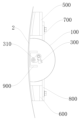
도 1은 본 개시내용의 실시예에 따른 폐쇄 위치에서의 외부 차량 도어 핸들의 핸들 그립의 개략적인 구조도이다.
도 2는 본 개시내용의 실시예에 따른 개방 위치에서의 외부 차량 도어 핸들의 핸들 그립의 개략적인 구조도이다.
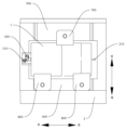
도 3은 본 개시내용의 실시예에 따른 외부 차량 도어 핸들의 개략적인 구조도이다.
도 4는 다른 시야각에서의 본 개시내용의 실시예에 따른 외부 차량 도어 핸들의 개략적인 구조도이다.
참조 번호:
외부 차량 도어 핸들(1), 외부 차량 도어 패널(2), 베이스(100), 핸들 공동(110), 핸들 그립(200), 회전 샤프트(210), 잠금해제 크랭크(300), 잠금해제 푸시 로드 버클(310), 핸들 개구(400), 제1 위치설정 돌출부(500), 제2 위치설정 돌출부(600), 제1 고정 러그(700), 제2 고정 러그(800), 제한 부분(900).The foregoing and/or additional aspects and advantages of the present disclosure will become apparent and understood from the following description of embodiments made with reference to the accompanying drawings.
1 is a schematic structural diagram of a handle grip of an external vehicle door handle in a closed position according to an embodiment of the present disclosure.
Figure 2 is a schematic structural diagram of a handle grip of an external vehicle door handle in an open position according to an embodiment of the present disclosure.
Figure 3 is a schematic structural diagram of an external vehicle door handle according to an embodiment of the present disclosure.
4 is a schematic structural diagram of an external vehicle door handle according to an embodiment of the present disclosure at different viewing angles.
Reference number:
Exterior vehicle door handle (1), exterior vehicle door panel (2), base (100), handle cavity (110), handle grip (200), rotating shaft (210), unlocking crank (300), unlocking push rod Buckle 310,
본 개시내용의 실시예들이 아래에 상세히 설명되고, 첨부 도면들을 참조하여 설명된 실시예들은 예시적이다.Embodiments of the present disclosure are described in detail below, and the embodiments described with reference to the accompanying drawings are exemplary.
본 개시내용의 설명에서, "중심", "종방향", "횡방향", "길이", "폭", "두께", "위", "아래", "전방", "후방", "좌측", "우측", "수직", "수평", "상부", "저부", "내부", "외부", "시계방향", "반시계방향", "축방향", "반경방향", 및 "원주방향"과 같은 용어들에 의해 나타낸 배향 또는 위치 관계들은 첨부 도면들에 기초하여 도시되는 배향 또는 위치 관계이고, 언급된 장치 또는 요소가 특정한 배향을 가져야 하거나 특정한 배향으로 구성 및 동작되어야 한다는 것을 표시하거나 암시하는 것이 아니라 단지 본 개시내용을 설명하고 설명을 단순화하기 위하여 이용되고, 따라서, 본 개시내용에 대한 제한으로서 해석되지 않아야 한다는 것이 이해되어야 한다.In the description of this disclosure, "center", "longitudinal", "transverse", "length", "width", "thickness", "top", "bottom", "front", "posterior", " “Left”, “Right”, “Vertical”, “Horizontal”, “Top”, “Bottom”, “Inside”, “Outside”, “Clockwise”, “Counterclockwise”, “Axial”, “Radial” Orientation or positional relationships indicated by terms such as ", and "circumferential direction" are orientations or positional relationships shown based on the accompanying drawings, and the referenced device or element must have a specific orientation or be constructed and operated in a specific orientation. It should be understood that they are used merely to explain and simplify the description of the present disclosure and are not intended to indicate or imply that the disclosure should be made, and therefore, should not be construed as a limitation on the present disclosure.
본 개시내용의 설명에서, "복수"는 2개 이상을 의미한다.In the description of this disclosure, “plural” means two or more.
본 개시내용의 실시예에 따른 외부 차량 도어 핸들(1)이 첨부 도면을 참조하여 아래에 설명된다.An exterior
도 1 내지 도 4에 도시된 바와 같이, 본 개시내용의 실시예에 따른 외부 차량 도어 핸들(1)은 베이스(100) 및 핸들 그립(200)을 포함한다.1 to 4, an external
베이스(100)는 핸들 공동(110)을 구비하고 차량 도어에 장착되도록 구성된다. 핸들 그립(200)은 폐쇄 위치와 개방 위치 사이에서 회전가능하게 베이스(100) 상에 장착된다. 핸들 그립(200)이 폐쇄 위치에 있을 때, 핸들 그립(200)의 외부 표면은 차량 도어의 외부 표면으로부터 돌출하지 않고 핸들 공동(110)을 덮으며, 핸들 그립(200)이 핸들 공동(110)의 내부를 향해 회전함으로써 폐쇄 위치로부터 개방 위치로 회전할 때, 핸들 그립(200)은 차량 도어의 외부 표면으로부터 돌출하지 않고 핸들 공동(110)이 노출된다.The
폐쇄 위치에 있는 핸들 그립(200)은 차량 도어가 잠금 상태에 있고 개방될 수 없다는 것을 지칭한다. 개방 위치에 있는 핸들 그립(200)은 차량 도어가 잠금해제 상태에 있는 것을 지칭하고, 사용자는 핸들 그립(200)을 당김으로써 차량 도어를 개방할 수 있다. 핸들 그립(200)을 폐쇄 위치로부터 개방 위치로 회전시킴으로써, 차량 도어는 잠금 상태로부터 잠금해제 상태로 변경하도록 제어될 수 있다.The
본 개시내용의 실시예에 따른 외부 차량 도어 핸들(1)에서, 베이스(100)는 핸들 공동(110)을 구비하고 차량 도어 상에 장착되도록 구성되어, 핸들 그립(200)이 폐쇄 위치와 개방 위치 사이에서 회전가능하게 베이스(100) 상에 장착된다. 외부 차량 도어 핸들(1)을 장착하기 위한 차량 도어 내부에 차량 도어 공간이 있다. 사용자가 핸들 그립(200)을 조작하기 위한 조작 공간이 핸들 공동(110)에 보유될 수 있고, 사용자는 핸들 그립(200)을 터치하고 차량 도어의 개방 및 폐쇄를 제어하기 위해 손을 베이스(100)의 핸들 공동(110)에 넣을 수 있다. 또한, 베이스(100)는 핸들 공동(110)을 차량 도어 내부의 다른 구성요소들로부터 분리할 수 있어, 사용자가 핸들 그립(200)을 터치하는 동안 다른 구성요소들을 터치하는 것을 방지하고, 핸들 공동(110)이 노출될 때 먼지 및 액체가 핸들 공동(110)을 통해 차량 도어 공간에 진입하는 것을 방지하며, 그에 의해 차량 도어 공간의 청결성을 보장하고 차량 도어 공간 내 부품들의 부식의 확률을 감소시킨다.In an exterior
또한, 핸들 그립(200)이 폐쇄 위치에 있을 때, 핸들 그립(200)의 외부 표면은 차량 도어의 외부 표면으로부터 돌출하지 않고 핸들 공동(110)을 덮으며, 핸들 그립(200)이 핸들 공동(110)의 내부를 향해 회전함으로써 폐쇄 위치로부터 개방 위치로 회전할 때, 핸들 그립(200)은 차량 도어의 외부 표면으로부터 돌출하지 않고 핸들 공동(110)이 노출된다.Additionally, when the
따라서, 핸들 그립(200)이 폐쇄 위치에 있을 때, 핸들 그립(200)은 은폐된 상태에 있고, 핸들 그립(200) 및 차량 도어는 더욱 일체로 보인다. 사용자가 차량 도어를 볼 때, 핸들 그립(200)은 눈에 거슬리지 않으며, 차량 도어의 외부 표면은 더 심미적이고 더 청결하다. 핸들 그립(200)이 폐쇄 위치로부터 개방 위치로 회전할 때, 핸들 그립(200)은 차량 도어의 내부를 향해 회전한다. 이 경우, 핸들 그립(200)은 여전히 차량 도어의 외부 표면으로부터 돌출하지 않아서, 핸들 그립(200)은 차량 도어의 외부에 노출되는 것이 방지될 수 있고, 핸들 그립(200)은 폐쇄 상태, 개방 상태, 또는 폐쇄 상태와 개방 상태 사이의 임의의 위치에 있는 것에 관계없이 은폐된 상태에 있다. 이러한 방식으로, 차량 도어는 잠금 상태 또는 잠금해제 상태에서 비교적 청결하고, 핸들 그립(200)은 차량 외부의 물체들과 충돌하거나 물체들을 스크래치하지 않을 것이며, 따라서 높은 사용 안전성이 달성된다. 또한, 온도가 비교적 낮을 때, 차량 도어의 외부 표면이 냉기로 인해 결빙되는 경우에도, 차량의 내부를 향한 핸들 그립(200)의 회전은 차량 도어의 외부 표면 상의 결빙에 의해 영향을 받지 않을 것이며, 따라서 온도가 비교적 낮을 때 핸들 그립(200)은 여전히 부드럽게 회전한다.Accordingly, when the
또한, 핸들 그립(200)이 폐쇄 위치로부터 개방 위치로 회전할 때, 핸들 공동(110)이 노출되며, 따라서 사용자는 핸들 그립(200)을 당김으로써 차량 도어를 개방하기 위해 핸들 공동(110)에 손을 넣을 수 있고, 더 양호한 사용 경험이 달성된다. 또한, 핸들 그립(200)이 폐쇄 위치 또는 개방 위치에 있을 때, 핸들 그립(200)은 차량 도어의 외부 표면으로부터 돌출하지 않는다. 이러한 방식으로, 차량이 주행하고 있을 때 핸들 그립(200)이 차량의 바람 저항을 증가시키는 것이 방지될 수 있어, 차량의 구동 저항이 더 작아지고, 그에 의해 차량의 에너지 소비가 감소된다.Additionally, when the
따라서, 본 개시내용의 실시예에 따른 외부 차량 도어 핸들(1)은 완전히 은폐될 수 있고, 정돈된 외관, 높은 사용 안전성, 편리한 회전, 낮은 바람 저항 등의 장점을 갖는다.Therefore, the external
본 개시내용의 일부 특정 실시예들에서, 도 1에 도시된 바와 같이, 핸들 그립(200)이 폐쇄 위치에 있을 때, 핸들 그립(200)의 외부 표면은 차량 도어의 외부 표면과 동일 평면에 있다.In some specific embodiments of the disclosure, as shown in Figure 1, when the
이러한 방식으로, 폐쇄 위치에 있을 때, 핸들 그립(200)은 은폐된 상태에 있을 수 있어서, 차량 도어의 외부 표면은 더 높은 무결성을 갖고 전체 차량은 더 높은 심미적 외관을 갖는다. 또한, 핸들 그립(200)과 차량 도어 사이의 조인트는 동일 평면으로 유지되어, 먼지가 쉽게 축적되지 않으며, 이는 차량 도어의 외부 표면을 더 청결하게 한다.In this way, when in the closed position, the
본 개시내용의 일부 특정 실시예들에서, 도 2 및 도 4에 도시된 바와 같이, 차량 도어는 핸들 공동(110)의 일 부분을 덮는다. 폐쇄 위치에 있을 때, 핸들 그립(200)은 핸들 공동(110)의 다른 부분을 덮고, 개방 위치에 있을 때, 핸들 그립(200)은, 차량 도어 내에서, 핸들 공동(110)을 덮는 차량 도어의 부분과 맞접한다.In some specific embodiments of the present disclosure, as shown in FIGS. 2 and 4 , the vehicle door covers a portion of the
예를 들어, 객실에서 멀어지는 방향을 향하는 베이스(100)의 일 측은 개방되어 있다. 핸들 그립(200)이 폐쇄 위치에 있을 때, 핸들 그립(200) 및 차량 도어는 베이스(100)의 개방 부분을 덮어, 핸들 공동(110)을 밀봉한다. 핸들 그립(200)이 개방 위치에 있을 때, 베이스(100)의 일 부분이 개방되어, 핸들 공동(110)과 외부 세계 사이의 연통을 달성한다. 또한, 베이스(100)의 단면의 외부 윤곽 및 내부 윤곽 양자 모두는 호-형상이다. 이러한 방식으로, 핸들 공동(110)의 균일한 벽 두께가 보장될 수 있고, 사람의 손을 위한 적절한 조작 공간을 보장하면서 베이스(100)의 재료, 중량 및 비용이 또한 감소될 수 있다. 또한, 베이스(100)는 균일하게 응력을 받고 쉽게 응력이 집중되지 않는다.For example, one side of the base 100 facing away from the guest room is open. When the
즉, 핸들 공동(110)의 단면적은 핸들 그립(200)의 단면적보다 크다. 이러한 방식으로, 핸들 그립(200)은 핸들 공동(110) 내에서 회전할 수 있어, 핸들 그립(200)이 개방 위치와 폐쇄 위치 사이에서 전환될 수 있다. 또한, 핸들 그립(200)이 폐쇄 위치에 있을 때, 사용자는 차량 도어에 의해 덮인 핸들 공동(110)의 부분에 손을 넣을 수 있고, 사용자가 핸들 그립(200)을 조작하기 위한 비교적 큰 조작 공간이 핸들 공동(110)에 보유될 수 있어, 조작을 더 편리하게 한다.That is, the cross-sectional area of the
본 개시내용의 일부 특정 실시예들에서, 도 2 및 도 3에 도시된 바와 같이, 핸들 그립(200)에는 회전 샤프트(210)가 제공된다. 핸들 그립(200)은 회전 샤프트(210)에 의해 베이스(100) 상에 회전가능하게 장착된다. 회전 샤프트(210)는, 핸들 그립(200)이 폐쇄 위치에 있을 때 핸들 그립(200)의 하부 에지에 위치된다.In some specific embodiments of the present disclosure, as shown in FIGS. 2 and 3, the
구체적으로, 회전 샤프트(210)는 수평 방향으로 연장될 수 있고, 회전 샤프트(210)의 양 단부는 핸들 그립(200)의 전방 측 및 후방 측으로부터 연장될 수 있다. 베이스(100)의 전방 측 및 후방 측에는 회전 샤프트 홀들이 제공될 수 있고, 회전 샤프트(210)의 양 단부는 회전 샤프트 홀들에 각각 끼워맞춤된다. 이러한 방식으로, 회전 샤프트(210)와 회전 샤프트 홀들 사이의 끼워맞춤에 의해, 핸들 그립(200)은 베이스(100)에 대해 회전할 수 있고, 회전 구조는 구현하기에 간단하고 용이하다. 더욱이, 회전 샤프트(210)는 비교적 작은 체적을 갖고, 차량 도어 상에 배열될 때 비교적 큰 공간을 점유할 필요가 없어, 배열을 더 편리하게 한다.Specifically, the
또한, 대부분의 사람들의 우세 손은 자연스러운 상황 하에서 자신의 오른손이고, 오른손의 손바닥은 일반적으로 왼쪽 또는 아래쪽으로 연장되기 때문에, 핸들 그립(200)의 하부 에지를 회전축으로 하여 핸들 그립(200)을 회전시키는 것은 인체의 힘을 가하는 습관들과 더욱 일치하고, 이에 의해 사용자에 의한 사용을 용이하게 한다.In addition, since most people's dominant hand is their right hand under natural circumstances, and the palm of the right hand generally extends to the left or downward, the
또한, 도 3 및 도 4에 도시된 바와 같이, 외부 차량 도어 핸들(1)은 구동 디바이스를 더 포함한다. 구동 디바이스는 차량 도어 록에 연결되도록 구성되고 핸들 그립(200)에 연결된다. 차량 도어 록이 잠금해제될 때, 구동 디바이스는 핸들 그립(200)을 개방 위치와 폐쇄 위치 사이의 중간 위치로 구동하고, 핸들 그립이 폐쇄 위치로부터 중간 위치로 회전하는 각도는 핸들 그립이 중간 위치로부터 개방 위치로 회전하는 각도보다 더 크다.Additionally, as shown in FIGS. 3 and 4, the external
즉, 폐쇄 위치로부터 개방 위치로 회전하는 과정에서, 핸들 그립(200)은 먼저 중간 위치를 통과한다. 핸들 그립(200)이 중간 위치에 있을 때, 차량 도어는 잠금해제 상태에 있고, 사용자는 핸들 그립(200)을 가압하고 이를 차량의 외부를 향해 당김으로써 차량 도어를 개방할 수 있고, 사용자가 핸들 그립(200)을 개방 위치로 누르지 않을 때, 차량 도어는 여전히 폐쇄 상태에 있다. 이러한 방식으로, 차량 도어는 사용자의 우발적인 터치로 인한 차량 도어의 직접 개방을 방지하기 위해 이중 잠금될 수 있어, 더 높은 안전성이 달성된다.That is, in the process of rotating from the closed position to the open position, the
예를 들어, 사용자는 차량의 블루투스 키에 의해 잠금해제 신호를 방출할 수 있고, 차량 도어 록은 잠금해제 신호를 수신한 후에 차량 도어를 잠금해제한다. 이 경우, 구동 디바이스는 핸들 공동(110)을 노출시키기 위해 핸들 그립(200)을 폐쇄 위치로부터 중간 위치로 회전하도록 동작 및 구동하며, 사용자는 차량 도어가 이미 잠금해제된 상태에 있는 것을 관찰할 수 있고, 그 후 손을 핸들 공동(110)에 넣고 핸들 그립(200)을 누르고 당김으로써 차량 도어를 열 수 있다.For example, the user may emit an unlocking signal by the vehicle's Bluetooth key, and the vehicle door lock unlocks the vehicle door after receiving the unlocking signal. In this case, the actuating device operates and drives the
선택적으로, 핸들 그립(200)은 핸들 공동(110)의 내부를 향해 110° 내지 120° 회전함으로써 폐쇄 위치로부터 중간 위치로 회전하고, 핸들 그립(200)은 핸들 공동(110)의 내부를 향해 50° 내지 60° 회전함으로써 중간 위치로부터 개방 위치로 회전하는데, 즉, 핸들 그립(200)은 폐쇄 위치로부터 개방 위치로 회전하기 위해 160° 내지 180° 회전할 필요가 있다.Optionally, the
핸들 그립(200)을 핸들 공동(110)의 내부를 향해 110° 내지 120° 로 회전시킴으로써, 한편으로는, 사용자가 손을 핸들 공동(110)에 넣는 것이 편리하고, 조작이 용이해지고; 다른 한편으로는, 핸들 그립(200)이 이 경우에 하향으로 경사진 상태에 있고, 손을 핸들 공동(110)에 넣은 후에, 사용자는 핸들 그립이 중간 위치에 있을 때 차량의 내측과 대면하는 핸들 그립(200)의 표면을 편리하게 가압할 수 있으며, 이로 인해 사용자는 차량 도어에 힘을 인가하고 차량 도어를 개방하도록 당기기 위해 차량의 외측을 향해 힘을 가할 수 있다.By rotating the
또한, 핸들 그립(200)은 중간 위치로부터 개방 위치로 회전하도록 50° 내지 60° 회전할 필요가 있다. 이러한 방식으로, 사용자는 핸들 그립(200)의 회전을 느낄 수 있어, 조작의 유효성을 더 직관적으로 느낄 수 있다. 또한, 핸들 그립(200)이 폐쇄 위치에 있을 때, 핸들 그립(200)의 외부 표면은 차량 도어의 외부 표면과 동일 평면에 있는데, 즉, 핸들 그립(200)은 수직 상태에 있다. 핸들 그립(200)은 폐쇄 위치로부터 개방 위치로 회전하기 위해 160° 내지 180° 회전할 필요가 있기 때문에, 즉, 핸들 그립(200)이 개방 위치에 있을 때, 핸들 그립(200)은 또한 거의 수직 상태에 있고, 핸들 그립(200)을 터치한 후에 손가락들이 힘을 가하는 것이 더 용이하다. 이러한 방식으로, 사용자가 핸들 그립(200)을 당기는 것이 더 편리하다. 사용자에 의해 핸들 그립(200)에 가해진 힘의 대부분은 차량 도어를 개방하도록 당기는 데 사용되며, 이는 더 노동 절약적이고 더 적은 에너지를 소비한다.Additionally, the
본 개시내용의 일부 실시예들에서, 구동 디바이스는 모터(도면들에 예시되지 않음)이다. 모터는 베이스(100) 외부에 장착된다. 모터는 핸들 그립(200)에 구동-연결되고 차량 도어 록의 통신을 위해 구성된다. 따라서, 차량 도어 록이 개방 후에, 신호가 모터에 전송될 수 있고, 모터는 잠금해제 신호에 따라 핸들 그립(200)을 회전하도록 제어할 수 있고, 그에 의해 차량 도어를 잠금해제하면서 핸들 그립(200)을 중간 위치로 회전시키고, 사용자 조작들을 더 용이하게 한다. 또한, 모터는 양호한 잠금 성능을 가지며, 핸들 그립(200)은 신뢰적으로 위치설정될 수 있다. 모터는 중간 위치로부터 폐쇄 위치로 핸들 그립(200)을 추가로 재설정할 수 있다.In some embodiments of the disclosure, the drive device is a motor (not illustrated in the figures). The motor is mounted outside the
본 개시내용의 일부 다른 실시예들에서, 도 3 및 도 4에 도시된 바와 같이, 구동 디바이스는 푸시 로드 및 잠금해제 크랭크(300)를 포함한다.In some other embodiments of the disclosure, as shown in FIGS. 3 and 4 , the drive device includes a push rod and an unlocking
구체적으로, 푸시 로드의 일 단부는 차량 도어 록에 구동-연결되도록 구성되고, 잠금해제 크랭크(300)는 핸들 그립(200)에 구동-연결되며 잠금해제 푸시 로드 버클(310)에 의해 푸시 로드의 다른 단부에 연결된다. 따라서, 잠금해제될 때, 차량 도어 록은 푸시 로드를 이동하도록 구동할 수 있고, 이어서 푸시 로드는 잠금해제 푸시 로드 버클(310)에 의해, 잠금해제 크랭크(300)를 회전하도록 구동하고, 회전하는 동안 잠금해제 크랭크(300)는 핸들 그립(200)을 중간 위치로 회전하도록 구동하여, 폐쇄 위치와 중간 위치 간 핸들 그립(200)의 회전을 구현할 수 있다.Specifically, one end of the push rod is configured to be drive-connected to the vehicle door lock, and the unlocking crank 300 is drive-connected to the
예를 들어, 잠금해제 크랭크(300)는 회전 샤프트(210)에 연결되고 회전 샤프트(210)와 동시적으로 회전할 수 있다. 회전 샤프트(210)의 후방 단부는 베이스(100)의 후방 단부 밖으로 연장된다. 잠금해제 크랭크(300)는 회전 샤프트(210)의 후방 단부에 연결된다. 잠금해제 크랭크(300)는 베이스(100)의 핸들 공동(110) 외부에 위치된다. 베이스(100)의 후방 단부 표면에는 제한 부분(900)이 제공될 수 있다. 제한 부분(900)은 차량 도어 록의 정상 사용이 잠금해제 크랭크(300)의 과도한 회전으로 인해 영향을 받는 것을 방지하기 위해 잠금해제 크랭크(300)의 회전 각도를 제한할 수 있다.For example, unlocking crank 300 may be connected to
또한, 핸들 그립(200)이 사람 손에 의해 중간 위치로부터 개방 위치로 밀릴 때, 회전 샤프트(210)는 푸시 로드를 이동하도록 밀기 위해 잠금해제 크랭크(300)를 회전하게 구동하고, 이에 의해 차량 도어 록을 완전히 잠금해제한다. 이 경우, 차량 도어는 승객 객실을 노출시키기 위해 차량 본체에 대해 회전할 수 있다.Additionally, when the
차량 도어 록은, 잠금해제 크랭크(300)에 의해, 핸들 그립(200)을 회전하도록 구동하는 데 사용된다. 이러한 방식으로, 다른 구동 메커니즘들(예컨대, 모터)을 추가로 제공할 필요가 없고, 외부 차량 도어 핸들(1)의 부품들의 수가 감소되어, 비용이 감소되고, 외부 차량 도어 핸들(1)의 소형화 및 경량 구성이 또한 용이해진다.The vehicle door lock is used to drive the
구동 디바이스가 모터일 때, 핸들 그립(200)은 여전히 잠금해제 크랭크(300)에 연결되고, 이 경우, 잠금해제 크랭크(300)는 핸들 그립(200)을 폐쇄 위치로부터 중간 위치로 구동하는 기능을 취하지 않을 수 있음에 유의해야 한다. 또한, 핸들 그립(200)을 폐쇄 위치로부터 중간 위치로 이동시키는 전술한 2개의 모드는 동시에 설정될 수 있다. 따라서, 2개의 모드 중 하나가 적절히 작동할 수 없을 때, 차량 도어를 개방하는 백업 방식이 존재하여, 차량 외부로부터 차량 도어를 개방하기 위한 더 다양한 모드들을 제공하고, 사용자에 의한 사용을 용이하게 한다.When the drive device is a motor, the
본 개시내용의 실시예에 따른 차량 도어 조립체는 첨부 도면을 참조하여 아래에서 설명된다. 차량 도어 조립체는 본 개시내용의 전술한 실시예에 따른 차량 도어 및 외부 차량 도어 핸들(1)을 포함한다.A vehicle door assembly according to an embodiment of the present disclosure is described below with reference to the accompanying drawings. A vehicle door assembly includes a vehicle door and an exterior vehicle door handle (1) according to the above-described embodiments of the present disclosure.
본 개시내용의 실시예에 따른 차량 도어 조립체에서, 외부 차량 도어 핸들(1)은 본 개시내용의 전술한 실시예에 따른 외부 차량 도어 핸들(1)을 사용함으로써 완전히 은폐될 수 있고, 정돈된 외관, 높은 사용 안전성, 편리한 회전, 낮은 바람 저항 등의 장점을 갖는다.In the vehicle door assembly according to the embodiment of the present disclosure, the exterior
본 개시내용의 일부 특정 실시예들에서, 도 1 내지 도 4에 도시된 바와 같이, 차량 도어는 외부 차량 도어 패널(2) 및 내부 차량 도어 패널을 포함한다. 외부 차량 도어 패널(2)은 내부 차량 도어 패널의 외측 상에 장착되는데, 즉, 외부 차량 도어 패널(2)은 객실로부터 멀어지는 방향을 향하는 내부 차량 도어 패널의 일 측 상에 장착된다. 베이스(100)는 외부 차량 도어 패널(2) 상에 장착되고, 외부 차량 도어 패널(2)과 내부 차량 도어 패널 사이에 배열된다. 외부 차량 도어 패널(2)에는 핸들 개구(400)가 제공되고, 핸들 개구(400)의 위치는 핸들 공동(110)의 위치에 대응한다.In some specific embodiments of the present disclosure, as shown in Figures 1-4, the vehicle door includes an exterior
예를 들어, 외부 차량 도어 패널(2) 및 내부 차량 도어 패널은 함께 구동 디바이스 및 외부 차량 도어 핸들(1)을 수용하기 위한 도어 패널 공간을 형성할 수 있어, 구동 디바이스 및 외부 차량 도어 핸들(1)이 보호될 수 있고, 차량 도어 조립체의 외부 표면이 또한 더 청결할 수 있으며, 그에 의해 차량 도어 조립체의 전체 조립 및 분해를 용이하게 한다. 또한, 외부 차량 도어 패널(2)의 외부 표면은 승객에 의한 접근을 용이하게 하기 위해 전체 차량의 외측에 위치된다. 외부 차량 도어 패널(2)에 핸들 개구(400)를 제공함으로써, 승객은 외부 차량 도어 핸들(1)에 더 편리하게 접근할 수 있다. 이러한 방식으로, 차량 도어의 개방이 더욱 편리하고 빠르다.For example, the outer
또한, 도 3 및 도 4에 도시된 바와 같이, 내부 차량 도어 패널과 대면하는 외부 차량 도어 패널(2)의 일 측에는 제1 위치설정 돌출부(500) 및 제2 위치설정 돌출부(600)가 제공된다. 베이스(100)는 제1 고정 러그(700) 및 제2 고정 러그들(800)을 구비한다. 베이스(100)는 제1 위치설정 돌출부(500)와 제2 위치설정 돌출부(600) 사이에 배열된다. 제1 고정 러그(700)는 내부 차량 도어 패널과 대면하는 제1 위치설정 돌출부(500)의 일 측 상에 고정되고, 제2 고정 러그들(800)은 내부 차량 도어 패널과 대면하는 제2 위치설정 돌출부(600)의 일 측 상에 고정된다.Additionally, as shown in FIGS. 3 and 4, a
예를 들어, 제1 고정 러그(700) 및 제1 위치설정 돌출부(500)는 볼트와 같은 나사형 체결구에 의해 연결될 수 있고, 제2 고정 러그(800) 및 제2 위치설정 돌출부(600)는 볼트와 같은 나사형 체결구에 의해 연결될 수 있다. 다수의 제1 고정 러그(700) 또는 다수의 제2 고정 러그(800)가 존재할 수 있다. 예를 들어, 2개의 제2 고정 러그(800) 및 1개의 제1 고정 러그(700)가 존재하고, 제1 고정 러그(700)는 전후 방향으로 2개의 제2 고정 러그(800) 사이에 위치될 수 있다. 이러한 방식으로, 제1 고정 러그(700) 및 제2 고정 러그들(800)을 베이스(100)의 길이 방향으로 엇갈린 방식으로 배열함으로써, 길이 방향으로 베이스(100)에 의해 수용되는 고정력이 더욱 균일하여, 베이스(100)의 위치를 더욱 안정되게 한다.For example, the
또한, 제1 위치설정 돌출부(500) 및 제2 위치설정 돌출부(600)는 둘 다 외부 차량 도어 패널(2)의 내측 표면으로부터 내부 차량 도어 패널을 향해 돌출되기 때문에, 제1 위치설정 돌출부(500)와 제2 위치설정 돌출부(600) 사이에 베이스(100)를 장착하는 것은 베이스(100)를 외부 차량 도어 패널(2)의 내측 표면에 더 가깝게 하거나, 심지어 외부 차량 도어 패널(2)의 내측 표면에 부착되게 한다. 이러한 방식으로, 외부 차량 도어 패널(2)의 내측 표면으로부터 돌출되는 베이스(100)의 부분의 크기가 더 작고, 외부 차량 도어 패널(2) 및 베이스(100)의 좌우 방향으로의 전체 크기의 감소가 용이하게 되어, 공간 활용이 개선될 수 있다.Additionally, since the
또한, 내부 차량 도어 패널과 대면하는 제1 위치설정 돌출부(500)의 일 측면 및 내부 차량 도어 패널과 대면하는 제2 위치설정 돌출부(600)의 일 측면은 각각 평면일 수 있다. 제1 고정 러그(700) 및 제2 고정 러그들(800)은 모두 상하 방향으로 연장되는 평면들이다. 이러한 방식으로, 제1 고정 러그(700)와 제1 위치설정 돌출부(500) 사이의 부착 영역이 더 크고, 각각의 제2 고정 러그(800)와 제2 위치설정 돌출부(600) 사이의 부착 영역이 더 커서, 베이스(100)와 외부 차량 도어 패널(2) 사이의 연결 강도의 향상이 용이해진다.Additionally, one side of the
제1 위치설정 돌출부(500)의 상부 에지와 제2 위치설정 돌출부(600)의 하부 에지 사이의 거리는 제1 고정 러그(700)의 상부 에지와 제2 고정 러그들(800)의 하부 에지들 사이의 거리보다 크다. 이러한 방식으로, 제1 고정 러그(700) 및 제2 고정 러그들(800)은 상하 방향으로 제1 위치설정 돌출부(500) 및 제2 위치설정 돌출부(600)로부터 돌출되지 않고, 베이스(100)의 고정은 더욱 신뢰적이다.The distance between the upper edge of the
본 개시내용의 일 실시예에 따른 차량이 첨부 도면을 참조하여 후술된다. 차량은 본 개시내용의 전술한 실시예에 따른 차량 도어 조립체를 포함한다.A vehicle according to an embodiment of the present disclosure is described below with reference to the accompanying drawings. A vehicle includes a vehicle door assembly according to the above-described embodiment of the present disclosure.
본 개시내용의 실시예에 따른 차량에서, 외부 차량 도어 핸들(1)은 본 개시내용의 전술한 실시예에 따른 차량 도어 조립체를 사용함으로써 완전히 은폐될 수 있고, 정돈된 외관, 높은 사용 안전성, 낮은 바람 저항 등의 장점을 갖는다.In a vehicle according to an embodiment of the present disclosure, the external
본 개시내용의 실시예들에 따른 외부 차량 도어 핸들(1), 차량 도어 조립체 및 차량의 다른 구성들 및 동작들은 본 기술분야의 통상의 기술자에게 알려져 있으며, 본 명세서에서는 상세하게 설명되지 않을 것이다.Other configurations and operations of the exterior
본 명세서의 설명들에서, "실시예", "일부 실시예들", "예시적인 실시예", "예", "특정 예", 또는 "일부 예들"이라는 참조 용어들을 사용하는 설명들은, 실시예 또는 예를 참조하여 설명된 특정 특성들, 구조들, 재료들, 또는 특징들이 본 출원의 적어도 하나의 실시예 또는 예에 포함된다는 것을 의미한다. 본 명세서에서, 상기 용어의 개략적인 설명이 반드시 동일한 실시예 또는 예를 지칭하는 것은 아니다.In the descriptions herein, descriptions using the reference terms “embodiment,” “some embodiments,” “exemplary embodiment,” “example,” “specific example,” or “some examples” refer to embodiments. It means that particular features, structures, materials, or features described with reference to an example or example are included in at least one embodiment or example of the present application. In this specification, schematic descriptions of the above terms do not necessarily refer to the same embodiment or example.
본 개시내용의 실시예들이 도시되고 설명되었지만, 본 기술분야의 통상의 기술자는 본 개시내용의 원리들 및 사상으로부터 벗어나지 않고 실시예들에 대한 다양한 변경들, 수정들, 대체들, 및 변형들이 이루어질 수 있음을 이해할 수 있으며, 본 개시내용의 범위는 첨부된 청구항들 및 그들의 등가물들에 의해 정의된다.Although embodiments of the disclosure have been shown and described, various changes, modifications, substitutions, and variations can be made to the embodiments without departing from the principles and spirit of the disclosure. It is understood that the scope of the present disclosure is defined by the appended claims and their equivalents.
Claims (12)
베이스 - 상기 베이스는 핸들 공동을 구비하고 차량 도어에 장착되도록 구성됨 -; 및
핸들 그립 - 상기 핸들 그립은 폐쇄 위치와 개방 위치 사이에서 회전가능하게 상기 베이스 상에 장착되고, 상기 핸들 그립이 상기 폐쇄 위치에 있을 때, 상기 핸들 그립의 외부 표면이 상기 차량 도어의 외부 표면으로부터 돌출하지 않고 상기 핸들 공동을 덮고, 상기 핸들 그립이 상기 핸들 공동의 내부를 향해 회전함으로써 상기 폐쇄 위치로부터 상기 개방 위치로 회전할 때, 상기 핸들 그립은 상기 차량 도어의 외부 표면으로부터 돌출하지 않고 상기 핸들 공동은 노출됨 - 을 포함하는, 외부 차량 도어 핸들.As an external vehicle door handle,
a base, the base having a handle cavity and configured to be mounted on a vehicle door; and
Handle grip - the handle grip is mounted on the base rotatably between a closed position and an open position, wherein when the handle grip is in the closed position, an outer surface of the handle grip protrudes from an outer surface of the vehicle door. does not cover the handle cavity, and when the handle grip rotates from the closed position to the open position by rotating toward the inside of the handle cavity, the handle grip does not protrude from the outer surface of the vehicle door and covers the handle cavity Exposed - Exterior vehicle door handles, including.
상기 핸들 그립이 상기 폐쇄 위치에 있을 때, 상기 핸들 그립의 상기 외부 표면은 상기 차량 도어의 상기 외부 표면과 동일 평면에 있는, 외부 차량 도어 핸들.According to paragraph 1,
An exterior vehicle door handle, wherein when the handle grip is in the closed position, the exterior surface of the handle grip is flush with the exterior surface of the vehicle door.
상기 차량 도어는 상기 핸들 공동의 일 부분을 덮고; 상기 폐쇄 위치에 있을 때, 상기 핸들 그립은 상기 핸들 공동의 다른 부분을 덮고; 상기 개방 위치에 있을 때, 상기 핸들 그립은, 상기 차량 도어 내에서, 상기 핸들 공동을 덮은 상기 차량 도어의 상기 부분과 맞접하는, 외부 차량 도어 핸들.According to claim 1 or 2,
the vehicle door covers a portion of the handle cavity; When in the closed position, the handle grip covers another portion of the handle cavity; When in the open position, the handle grip abuts, within the vehicle door, the portion of the vehicle door that covers the handle cavity.
상기 핸들 그립은 회전 샤프트를 구비하고, 상기 핸들 그립은 상기 회전 샤프트에 의해 상기 베이스 상에 회전가능하게 장착되고, 상기 회전 샤프트는 상기 핸들 그립이 상기 폐쇄 위치에 있을 때 상기 핸들 그립의 하부 에지에 위치되는, 외부 차량 도어 핸들.According to any one of claims 1 to 3,
The handle grip includes a rotating shaft, the handle grip being rotatably mounted on the base by the rotating shaft, the rotating shaft being positioned at a lower edge of the handle grip when the handle grip is in the closed position. Located on the exterior vehicle door handle.
구동 디바이스 - 상기 구동 디바이스는 차량 도어 록에 연결되고 상기 핸들 그립에 연결되도록 구성되고, 상기 구동 디바이스는 상기 차량 도어 록이 잠금해제될 때 상기 핸들 그립을 상기 개방 위치와 상기 폐쇄 위치 사이의 중간 위치로 구동함 - 를 더 포함하고;
상기 핸들 그립이 상기 폐쇄 위치로부터 상기 중간 위치로 회전하는 각도는 상기 핸들 그립이 상기 중간 위치로부터 상기 개방 위치로 회전하는 각도보다 큰, 외부 차량 도어 핸들.According to any one of claims 1 to 4,
Driving device - the driving device is connected to a vehicle door lock and configured to be connected to the handle grip, wherein the driving device moves the handle grip to an intermediate position between the open position and the closed position when the vehicle door lock is unlocked. Driven by - further includes;
An exterior vehicle door handle, wherein the angle through which the handle grip rotates from the closed position to the intermediate position is greater than the angle through which the handle grip rotates from the intermediate position to the open position.
상기 핸들 그립은 상기 핸들 공동의 내부를 향해 110° 내지 120° 회전함으로써 상기 폐쇄 위치로부터 상기 중간 위치로 회전하도록 구성되고;
상기 핸들 그립은 상기 핸들 공동의 내부를 향해 50° 내지 60° 회전함으로써 상기 중간 위치로부터 상기 개방 위치로 회전하도록 구성되는, 외부 차량 도어 핸들.According to clause 5,
the handle grip is configured to rotate from the closed position to the intermediate position by rotating 110° to 120° toward the interior of the handle cavity;
wherein the handle grip is configured to rotate from the intermediate position to the open position by rotating 50° to 60° toward the interior of the handle cavity.
상기 구동 디바이스는 모터이고, 상기 모터는 상기 베이스 외부에 장착되고, 상기 모터는 상기 핸들 그립에 구동-연결되고 상기 차량 도어 록의 통신을 위해 구성되는, 외부 차량 도어 핸들.According to claim 5 or 6,
wherein the drive device is a motor, the motor mounted outside the base, the motor drive-connected to the handle grip and configured for communication of the vehicle door lock.
상기 구동 디바이스는,
푸시 로드 - 상기 푸시 로드의 일 단부는 상기 차량 도어 록에 구동-연결되도록 구성됨 -; 및
잠금해제 크랭크 - 상기 잠금해제 크랭크는 상기 핸들 그립에 구동-연결되고 잠금해제 푸시 로드 버클에 의해 상기 푸시 로드의 다른 단부에 연결됨 - 를 포함하는, 외부 차량 도어 핸들.According to any one of claims 5 to 7,
The driving device is,
a push rod, one end of which is configured to be drive-connected to the vehicle door lock; and
An exterior vehicle door handle, comprising an unlocking crank, the unlocking crank being drive-connected to the handle grip and connected to the other end of the push rod by an unlocking push rod buckle.
차량 도어; 및
제1항 내지 제8항 중 어느 한 항에 따른 외부 차량 도어 핸들을 포함하는, 차량 도어 조립체.A vehicle door assembly, comprising:
vehicle doors; and
A vehicle door assembly comprising an exterior vehicle door handle according to any one of claims 1 to 8.
상기 차량 도어는,
외부 차량 도어 패널 및 내부 차량 도어 패널을 포함하고, 상기 외부 차량 도어 패널은 상기 내부 차량 도어 패널의 외측 상에 장착되고, 상기 베이스는 상기 외부 차량 도어 패널 상에 장착되고 상기 외부 차량 도어 패널과 상기 내부 차량 도어 패널 사이에 배열되며, 상기 외부 차량 도어 패널은 핸들 개구를 구비하고, 상기 핸들 개구의 위치는 상기 핸들 공동의 위치에 대응하는, 차량 도어 조립체.According to clause 9,
The vehicle door is,
an exterior vehicle door panel and an interior vehicle door panel, the exterior vehicle door panel being mounted on an outside of the interior vehicle door panel, the base being mounted on the exterior vehicle door panel, the exterior vehicle door panel and the base being mounted on the exterior vehicle door panel. A vehicle door assembly arranged between an inner vehicle door panel, wherein the outer vehicle door panel has a handle opening, the location of the handle opening corresponding to the location of the handle cavity.
상기 내부 차량 도어 패널과 대면하는 상기 외부 차량 도어 패널의 일 측에는 상하 방향으로 이격된 제1 위치설정 돌출부 및 제2 위치설정 돌출부가 제공되고; 상기 베이스에는 제1 고정 러그 및 제2 고정 러그들이 제공되고; 상기 베이스는 상기 제1 위치설정 돌출부와 상기 제2 위치설정 돌출부 사이에 배열되고; 상기 제1 고정 러그는 상기 내부 차량 도어 패널과 대면하는 상기 제1 위치설정 돌출부의 일 측 상에 고정되고; 상기 제2 고정 러그들은 상기 내부 차량 도어 패널과 대면하는 상기 제2 위치설정 돌출부의 일 측 상에 고정되는, 차량 도어 조립체.According to clause 10,
A first positioning protrusion and a second positioning protrusion spaced apart in the vertical direction are provided on one side of the outer vehicle door panel facing the inner vehicle door panel; The base is provided with first fixing lugs and second fixing lugs; the base is arranged between the first positioning protrusion and the second positioning protrusion; the first securing lug is secured on a side of the first positioning protrusion facing the interior vehicle door panel; wherein the second securing lugs are secured on a side of the second positioning protrusion facing the interior vehicle door panel.
Priority Applications (1)
| Application Number | Priority Date | Filing Date | Title |
|---|---|---|---|
| KR1020267020716A KR20260109988A (en) | 2021-11-30 | 2022-11-18 | Exterior vehicle door handle, vehicle door assembly, and vehicle |
Applications Claiming Priority (3)
| Application Number | Priority Date | Filing Date | Title |
|---|---|---|---|
| CN202111451995.XA CN116201423B (en) | 2021-11-30 | 2021-11-30 | Door outer handle, door assembly and vehicle |
| CN202111451995.X | 2021-11-30 | ||
| PCT/CN2022/132964 WO2023098494A1 (en) | 2021-11-30 | 2022-11-18 | Exterior vehicle door handle, vehicle door assembly, and vehicle |
Related Child Applications (1)
| Application Number | Title | Priority Date | Filing Date |
|---|---|---|---|
| KR1020267020716A Division KR20260109988A (en) | 2021-11-30 | 2022-11-18 | Exterior vehicle door handle, vehicle door assembly, and vehicle |
Publications (2)
| Publication Number | Publication Date |
|---|---|
| KR20240042658A true KR20240042658A (en) | 2024-04-02 |
| KR102986241B1 KR102986241B1 (en) | 2026-07-03 |
Family
ID=86510054
Family Applications (2)
| Application Number | Title | Priority Date | Filing Date |
|---|---|---|---|
| KR1020247008337A Active KR102986241B1 (en) | 2021-11-30 | 2022-11-18 | Exterior vehicle door handle, vehicle door assembly and vehicle |
| KR1020267020716A Pending KR20260109988A (en) | 2021-11-30 | 2022-11-18 | Exterior vehicle door handle, vehicle door assembly, and vehicle |
Family Applications After (1)
| Application Number | Title | Priority Date | Filing Date |
|---|---|---|---|
| KR1020267020716A Pending KR20260109988A (en) | 2021-11-30 | 2022-11-18 | Exterior vehicle door handle, vehicle door assembly, and vehicle |
Country Status (7)
| Country | Link |
|---|---|
| US (1) | US20240263495A1 (en) |
| EP (1) | EP4394154A4 (en) |
| JP (1) | JP7771370B2 (en) |
| KR (2) | KR102986241B1 (en) |
| CN (6) | CN120719877A (en) |
| AU (1) | AU2022401899B2 (en) |
| WO (1) | WO2023098494A1 (en) |
Families Citing this family (2)
| Publication number | Priority date | Publication date | Assignee | Title |
|---|---|---|---|---|
| CN120719877A (en) * | 2021-11-30 | 2025-09-30 | 比亚迪股份有限公司 | Door exterior handles, door assemblies and vehicles |
| CN116791980B (en) * | 2023-06-29 | 2025-07-25 | 浙江吉利控股集团有限公司 | Concealed vehicle door handle and control method of lock body |
Family Cites Families (28)
| Publication number | Priority date | Publication date | Assignee | Title |
|---|---|---|---|---|
| JPS605977A (en) * | 1983-06-24 | 1985-01-12 | 株式会社アルファ | Door handle for automobile |
| FR2580022B1 (en) * | 1985-04-05 | 1987-06-26 | Renault | |
| US4652030A (en) * | 1985-04-17 | 1987-03-24 | Street Specialty Products Inc. | Repair spring for vehicle door latch/handle assembly |
| JPS63223276A (en) * | 1987-03-11 | 1988-09-16 | ダイハツ工業株式会社 | Structure of outer handle in car door |
| KR0140675Y1 (en) * | 1996-11-28 | 1999-04-01 | 대우자동차 주식회사 | Door inside handle having an interception circuit to dust |
| JPH1193466A (en) * | 1997-09-19 | 1999-04-06 | Toyota Motor Corp | Outside door safety device for car doors |
| JPH11293969A (en) * | 1998-04-09 | 1999-10-26 | Nissan Motor Co Ltd | Mounting structure of outer handle unit |
| KR100931160B1 (en) * | 2007-12-17 | 2009-12-10 | 현대자동차주식회사 | Hidden Type Outside Handle |
| KR101327034B1 (en) * | 2011-12-06 | 2013-11-07 | 현대자동차주식회사 | Hidden type outside handle |
| US9617764B2 (en) * | 2013-04-03 | 2017-04-11 | AISIN Technical Center of America, Inc. | Hidden flush outside handle |
| US9518410B2 (en) * | 2014-05-01 | 2016-12-13 | AISIN Technical Center of America, Inc. | Flush mounted vehicle handle |
| DE102014113495A1 (en) * | 2014-09-18 | 2016-03-24 | Huf Hülsbeck & Fürst Gmbh & Co. Kg | Door handle assembly for a motor vehicle |
| GB2548145B (en) * | 2016-03-10 | 2021-03-31 | Bentley Motors Ltd | Door handle assembly |
| JP6769005B2 (en) * | 2016-11-30 | 2020-10-14 | 株式会社ユーシン | Door handle device |
| US10738513B2 (en) * | 2016-12-09 | 2020-08-11 | Toyota Motor Engineering & Manufacturing North America, Inc. | Flush power slide door handle |
| CN109854104B (en) * | 2017-11-30 | 2020-10-23 | 长城汽车股份有限公司 | Hidden door handle, control method thereof and automobile |
| CN108222714B (en) * | 2018-02-05 | 2023-07-14 | 东方久乐汽车电子(上海)股份有限公司 | Improved hidden automobile door handle mechanism |
| EP3620599B1 (en) * | 2018-09-05 | 2021-01-27 | U-Shin Deutschland Zugangssysteme GmbH | Coupling device for vehicle flush door handle assembly |
| CN109296273A (en) * | 2018-11-29 | 2019-02-01 | 上汽大众汽车有限公司 | hidden door handle |
| DE102019003566A1 (en) * | 2019-05-22 | 2020-11-26 | Knorr-Bremse Gesellschaft Mit Beschränkter Haftung | Vehicle with an outer door device arranged on an outer wall |
| CN210370269U (en) * | 2019-06-21 | 2020-04-21 | 上海翼锐汽车科技有限公司 | Take hidden door handle of upset of atmosphere lamp |
| CN110409940B (en) * | 2019-08-30 | 2024-03-26 | 宁波华德汽车零部件有限公司 | Electronic unlocking mechanical automobile door handle |
| US11851920B2 (en) * | 2020-04-28 | 2023-12-26 | Magna Mirrors Of America, Inc. | Vehicular exterior door handle assembly with light projection and gesture sensing |
| DE102020117046B3 (en) * | 2020-06-29 | 2021-09-23 | Dr. Ing. H.C. F. Porsche Aktiengesellschaft | Door handle assembly for a vehicle door |
| CN112576122A (en) * | 2020-12-29 | 2021-03-30 | 无锡忻润汽车安全系统有限公司 | Hidden handle turning-in mechanism |
| CN112922469B (en) * | 2021-03-30 | 2025-09-09 | 浙江吉利控股集团有限公司 | Door handle assembly for vehicle and door |
| CN113153035B (en) * | 2021-04-26 | 2024-09-20 | 伟速达(荆州)汽车安全系统有限公司 | Inward-turned door handle and working method |
| CN120719877A (en) * | 2021-11-30 | 2025-09-30 | 比亚迪股份有限公司 | Door exterior handles, door assemblies and vehicles |
-
2021
- 2021-11-30 CN CN202511045595.7A patent/CN120719877A/en active Pending
- 2021-11-30 CN CN202511047380.9A patent/CN120844859A/en active Pending
- 2021-11-30 CN CN202511047869.6A patent/CN120666976A/en active Pending
- 2021-11-30 CN CN202511057639.8A patent/CN120844860A/en active Pending
- 2021-11-30 CN CN202111451995.XA patent/CN116201423B/en active Active
- 2021-11-30 CN CN202511055623.3A patent/CN120666977A/en active Pending
-
2022
- 2022-11-18 KR KR1020247008337A patent/KR102986241B1/en active Active
- 2022-11-18 AU AU2022401899A patent/AU2022401899B2/en active Active
- 2022-11-18 WO PCT/CN2022/132964 patent/WO2023098494A1/en not_active Ceased
- 2022-11-18 KR KR1020267020716A patent/KR20260109988A/en active Pending
- 2022-11-18 JP JP2024518125A patent/JP7771370B2/en active Active
- 2022-11-18 EP EP22900299.3A patent/EP4394154A4/en active Pending
-
2024
- 2024-04-03 US US18/625,285 patent/US20240263495A1/en active Pending
Also Published As
| Publication number | Publication date |
|---|---|
| KR20260109988A (en) | 2026-07-13 |
| EP4394154A1 (en) | 2024-07-03 |
| CN120844860A (en) | 2025-10-28 |
| JP7771370B2 (en) | 2025-11-17 |
| CN116201423B (en) | 2025-09-09 |
| KR102986241B1 (en) | 2026-07-03 |
| CN120666977A (en) | 2025-09-19 |
| WO2023098494A1 (en) | 2023-06-08 |
| JP2024541799A (en) | 2024-11-13 |
| CN120666976A (en) | 2025-09-19 |
| AU2022401899A1 (en) | 2024-04-04 |
| EP4394154A4 (en) | 2025-01-29 |
| US20240263495A1 (en) | 2024-08-08 |
| CN116201423A (en) | 2023-06-02 |
| CN120844859A (en) | 2025-10-28 |
| AU2022401899B2 (en) | 2025-08-28 |
| CN120719877A (en) | 2025-09-30 |
Similar Documents
| Publication | Publication Date | Title |
|---|---|---|
| US20240263495A1 (en) | Exterior vehicle door handle, vehicle door assembly and vehicle | |
| US11396764B2 (en) | Door handle assembly | |
| CN203669511U (en) | Doorknob device | |
| US6009932A (en) | Push to exit, pull to enter latch assembly for screen door | |
| US8833120B2 (en) | Locking mechanism with integral egress release | |
| EP3042013B1 (en) | Motor vehicle door with a handle and a lock | |
| JP2002147069A (en) | Sliding door inner handle assembly | |
| CN105239856A (en) | Door lock device and storage box with same | |
| CN106930605A (en) | Handle mechanism and the handle lock with the mechanism that a kind of anti-opal is opened | |
| US20160215534A1 (en) | Vehicle door latch for preventing locking | |
| CN110593681A (en) | Concealed door handle | |
| US12151543B2 (en) | Release system for removable vehicle panel | |
| CN207110693U (en) | The handle mechanism that a kind of anti-opal is opened | |
| CN205078048U (en) | Door lock device and storage box with same | |
| JP2006504008A (en) | Car door handle | |
| KR102127881B1 (en) | Door lock assembly of vehicle | |
| JP2002030834A (en) | Outside handle of back door | |
| CN222436134U (en) | Car door inner buckle mounting structure and car | |
| CN222025607U (en) | Semi-concealed door handle, door and vehicle | |
| CN216549151U (en) | Household elevator door capable of getting rid of poverty automatically | |
| KR100691211B1 (en) | Inside handle module | |
| JPH076423Y2 (en) | Car door lock | |
| CN211598114U (en) | Unlocking mechanism and push-pull lock with same | |
| KR200175572Y1 (en) | Trajectory Type Door Outside Handle | |
| TR2024014955A1 (en) | BONNET AND DOOR UNLOCK SYSTEM WITH MECHANICAL KEY |
Legal Events
| Date | Code | Title | Description |
|---|---|---|---|
| P11-X000 | Amendment of application requested |
St.27 status event code: A-2-2-P10-P11-nap-X000 |
|
| P13-X000 | Application amended |
St.27 status event code: A-2-2-P10-P13-nap-X000 |
|
| PA0105 | International application |
St.27 status event code: A-0-1-A10-A15-nap-PA0105 |
|
| PA0201 | Request for examination |
St.27 status event code: A-1-2-D10-D11-exm-PA0201 |
|
| PG1501 | Laying open of application |
St.27 status event code: A-1-1-Q10-Q12-nap-PG1501 |
|
| R18-X000 | Changes to party contact information recorded |
St.27 status event code: A-3-3-R10-R18-oth-X000 |
|
| D13-X000 | Search requested |
St.27 status event code: A-1-2-D10-D13-srh-X000 |
|
| E902 | Notification of reason for refusal | ||
| PE0902 | Notice of grounds for rejection |
St.27 status event code: A-1-2-D10-D21-exm-PE0902 |
|
| E13 | Pre-grant limitation requested |
Free format text: ST27 STATUS EVENT CODE: A-2-3-E10-E13-LIM-X000 (AS PROVIDED BY THE NATIONAL OFFICE) |
|
| E13-X000 | Pre-grant limitation requested |
St.27 status event code: A-2-3-E10-E13-lim-X000 |
|
| P11 | Amendment of application requested |
Free format text: ST27 STATUS EVENT CODE: A-2-2-P10-P11-NAP-X000 (AS PROVIDED BY THE NATIONAL OFFICE) |
|
| P11-X000 | Amendment of application requested |
St.27 status event code: A-2-2-P10-P11-nap-X000 |
|
| D22 | Grant of ip right intended |
Free format text: ST27 STATUS EVENT CODE: A-1-2-D10-D22-EXM-PE0701 (AS PROVIDED BY THE NATIONAL OFFICE) |
|
| PE0701 | Decision of registration |
St.27 status event code: A-1-2-D10-D22-exm-PE0701 |
|
| A16 | Divisional, continuation or continuation in part application filed |
Free format text: ST27 STATUS EVENT CODE: A-0-1-A10-A16-DIV-PA0104 (AS PROVIDED BY THE NATIONAL OFFICE) |
|
| PA0104 | Divisional application for international application |
St.27 status event code: A-0-1-A10-A16-div-PA0104 |
|
| F11 | Ip right granted following substantive examination |
Free format text: ST27 STATUS EVENT CODE: A-2-4-F10-F11-EXM-PR0701 (AS PROVIDED BY THE NATIONAL OFFICE) |
|
| PR0701 | Registration of establishment |
St.27 status event code: A-2-4-F10-F11-exm-PR0701 |
|
| PR1002 | Payment of registration fee |
St.27 status event code: A-2-2-U10-U12-oth-PR1002 Fee payment year number: 1 |
|
| U12 | Designation fee paid |
Free format text: ST27 STATUS EVENT CODE: A-2-2-U10-U12-OTH-PR1002 (AS PROVIDED BY THE NATIONAL OFFICE) Year of fee payment: 1 |
|
| PG1601 | Publication of registration |
St.27 status event code: A-4-4-Q10-Q13-nap-PG1601 |
|
| Q13 | Ip right document published |
Free format text: ST27 STATUS EVENT CODE: A-4-4-Q10-Q13-NAP-PG1601 (AS PROVIDED BY THE NATIONAL OFFICE) |