KR20220115026A - Easy to construction suspension system - Google Patents
Easy to construction suspension system Download PDFInfo
- Publication number
- KR20220115026A KR20220115026A KR1020210070323A KR20210070323A KR20220115026A KR 20220115026 A KR20220115026 A KR 20220115026A KR 1020210070323 A KR1020210070323 A KR 1020210070323A KR 20210070323 A KR20210070323 A KR 20210070323A KR 20220115026 A KR20220115026 A KR 20220115026A
- Authority
- KR
- South Korea
- Prior art keywords
- tube body
- nut tube
- hanger
- hanger body
- suspension system
- Prior art date
- Legal status (The legal status is an assumption and is not a legal conclusion. Google has not performed a legal analysis and makes no representation as to the accuracy of the status listed.)
- Granted
Links
Images



Classifications
-
- E—FIXED CONSTRUCTIONS
- E04—BUILDING
- E04B—GENERAL BUILDING CONSTRUCTIONS; WALLS, e.g. PARTITIONS; ROOFS; FLOORS; CEILINGS; INSULATION OR OTHER PROTECTION OF BUILDINGS
- E04B9/00—Ceilings; Construction of ceilings, e.g. false ceilings; Ceiling construction with regard to insulation
- E04B9/18—Means for suspending the supporting construction
- E04B9/20—Means for suspending the supporting construction adjustable
-
- E—FIXED CONSTRUCTIONS
- E04—BUILDING
- E04B—GENERAL BUILDING CONSTRUCTIONS; WALLS, e.g. PARTITIONS; ROOFS; FLOORS; CEILINGS; INSULATION OR OTHER PROTECTION OF BUILDINGS
- E04B9/00—Ceilings; Construction of ceilings, e.g. false ceilings; Ceiling construction with regard to insulation
- E04B9/06—Ceilings; Construction of ceilings, e.g. false ceilings; Ceiling construction with regard to insulation characterised by constructional features of the supporting construction, e.g. cross section or material of framework members
Landscapes
- Engineering & Computer Science (AREA)
- Architecture (AREA)
- Physics & Mathematics (AREA)
- Electromagnetism (AREA)
- Civil Engineering (AREA)
- Structural Engineering (AREA)
- Mutual Connection Of Rods And Tubes (AREA)
Abstract
본 발명은 시공이 편리한 서스펜션 시스템에 관한 것으로서, 더욱 상세하게는 조인트모듈의 너트관체가 행거본체 단부에 자유 회전되도록 구속되어 현장에서 전산볼트와의 조립 시공성이 향상되고, 특히, 너트관체에 형성되는 확인구 및 눈금표식부를 이용하여 행거본체 높낮이 조절에 따른 이동 거리를 정밀하게 검출함과 더불어 행거본체 이동 거리 정보를 이용하여 비숙련공도 쉽게 행거본체들 간에 높낮이 세팅작업을 정밀하게 수행할 수 있는 시공이 편리한 서스펜션 시스템을 제공한다.The present invention relates to a suspension system that is easy to construct, and more particularly, the nut tube body of the joint module is constrained to rotate freely at the end of the hanger body, so that assembly workability with the computerized bolt is improved in the field, and in particular, the nut tube body formed in the nut tube body A construction that precisely detects the movement distance according to the height adjustment of the hanger body using the check tool and the scale mark, and also uses the information on the movement distance of the hanger body so that even unskilled workers can easily perform the height setting work between the hanger bodies precisely. This provides a convenient suspension system.
Description
본 발명은 시공이 편리한 서스펜션 시스템에 관한 것으로서, 더욱 상세하게는 조인트모듈의 너트관체가 행거본체 단부에 자유 회전되도록 구속되어 현장에서 전산볼트와의 조립 시공성이 향상되고, 특히, 너트관체에 형성되는 확인구 및 눈금표식부를 이용하여 행거본체 높낮이 조절에 따른 이동 거리를 정밀하게 검출함과 더불어 행거본체 이동 거리 정보를 이용하여 비숙련공도 쉽게 행거본체들 간에 높낮이 세팅작업을 정밀하게 수행할 수 있는 시공이 편리한 서스펜션 시스템에 관한 것이다.The present invention relates to a suspension system that is easy to construct, and more particularly, the nut tube body of the joint module is constrained to rotate freely at the end of the hanger body, so that assembly workability with the computerized bolt is improved in the field, and in particular, the nut tube body formed in the nut tube body A construction that precisely detects the movement distance according to the height adjustment of the hanger body using the check tool and the scale mark, and also uses the information on the movement distance of the hanger body so that even unskilled workers can easily perform the height setting work between the hanger bodies precisely. It is about this convenient suspension system.
통상적으로 아파트, 빌딩, 오피스텔 등 건축물 천장의 전기배선으로 인하여 미관상 좋지 못한 부분을 은닉시켜 주거나 감전으로부터의 안전을 도모하기 위하여 천정패널은 시공된다.In general, ceiling panels are constructed to hide unsightly parts due to electrical wiring on the ceilings of buildings, such as apartments, buildings, and officetels, or to promote safety from electric shock.
이러한 천정패널이 설치되기 위해서는 슬라브 하측에 고정부재를 설치하고, 고정부재의 하측으로 채널부재 및 엠바 등이 설치되며, 고정부재와 채널부재를 연결하기 위해 행거를 사용하게 되는데, 이때 행거에 볼트가 삽입되어 고정부재와 연결되지만, 볼트에 삽입된 행거의 높낮이 조절에 어려움이 따랐다.In order to install such a ceiling panel, a fixing member is installed on the lower side of the slab, a channel member and an embar are installed below the fixing member, and a hanger is used to connect the fixing member and the channel member. At this time, a bolt is installed on the hanger. It is inserted and connected to the fixing member, but it is difficult to adjust the height of the hanger inserted into the bolt.
이에 종래에 개시된 등록특허 10-1973319호에서, 판 형태의 몸체; 상기 몸체의 상부가 측방향으로 연장 절곡되고, 구멍 형태의 앵커 체결구가 형성된 상부 절곡편; 상기 몸체의 하부가 연장 절곡되어 몸체와 소정 간격 이격되어 형성된 하부 절곡편; 상기 하부 절곡편과 몸체 사이에 형성되어 프레임이 삽입되는 프레임 삽입구; 상기 몸체의 양측에 몸체와 수직하는 방향으로 상부 절곡편 또는 하부 절곡편까지 연장되어 돌출된 보강리브; 및 상기 몸체와 상부 절곡편의 경계부 또는 몸체와 하부 절곡편의 경계부에 형성된 보강리브에 형성된 벤딩홈;을 포함하는 기술이 선 제시된 바 있다.Accordingly, in Patent No. 10-1973319 disclosed in the prior art, a plate-shaped body; The upper portion of the body is bent extending in the lateral direction, the upper bent piece is formed with an anchor fastener in the form of a hole; a lower bent piece formed by extending and bending the lower portion of the body to be spaced apart from the body by a predetermined distance; a frame insertion hole formed between the lower bent piece and the body into which the frame is inserted; Reinforcing ribs protruding from both sides of the body to the upper bent piece or the lower bent piece in a direction perpendicular to the body; and a bending groove formed in the reinforcing rib formed at the boundary between the body and the upper bent piece or at the boundary between the body and the lower bent piece;
그러나, 상기 종래기술은 볼트를 행거에 고정할 때, 몸체로 인해 나사 조임이 어렵고, 나사 조임을 위한 공간이 부족하여 작업 속도가 지연되며, 나사 조임시 행거 위치조절에 따른 이동 거리를 직관적으로 확인할 수 없어 수평도가 정밀하게 유지되지 못하는 문제점이 따랐다.However, in the prior art, when fixing the bolt to the hanger, it is difficult to fasten the screw due to the body, the work speed is delayed due to insufficient space for fastening the screw, and the moving distance according to the hanger position adjustment is intuitively confirmed when the screw is tightened. There was a problem that the horizontality could not be accurately maintained.
또한, 다른 종래기술인 등록특허 10-0865088호에서, 콘크리트 천정에 매설된 전산볼트와, 이 전산볼트에 체결되고, 그 하단에 'ㄷ'자 형상의 채널부재를 조립하는 지지대를 포함하는 천정 패널 고정용 행거에 있어서, 상기 전산볼트와 분리 결합되며, 지지대에 삽입시켜 고정하기 위한 행거브라켓과; 상기 행거브라켓을 끼워 결합하는 행거브라켓 제1,2삽입홈을 형성하고, 그 배면에는 행거브라켓 제1,2삽입홈의 중앙부 상의 관통하는 고정핀을 지지하여 외부의 충격에도 이탈하지 않도록 돌출 설치되는 돌출부를 형성하는 고정체결부를 구비하는 기술이 선 등록된바 있지만, 행거브라켓을 전산볼트에 고정하는 구조가 복잡하고, 고정이 안정적이지 못하며, 행거브라켓 높낮이 조절에 따른 미세 위치조절이 불가능한 문제점이 따랐다In addition, in Patent Registration No. 10-0865088, which is another prior art, a ceiling panel including a computerized bolt embedded in the concrete ceiling, a support for assembling a 'C'-shaped channel member at the lower end of which is fastened to the computerized bolt. A hanger for a hanger, comprising: a hanger bracket separately coupled to the computerized bolt and fixed by being inserted into a support; The hanger bracket first and second insertion grooves are formed for fitting the hanger brackets together, and the rear surface of the hanger bracket supports the fixing pins penetrating on the center of the first and second insertion grooves so as not to be separated from external impact. Although the technology of having a fixing and fastening part forming a protrusion has been previously registered, the structure for fixing the hanger bracket to the computerized bolt is complicated, the fixing is not stable, and there are problems that it is impossible to finely adjust the position according to the height adjustment of the hanger bracket.
그리고, 등록특허 10-0979167호에서, 중앙에 볼트가 삽입되는 볼트삽입공이 형성된 상단; 상기 상단의 일단에 직각으로 연장된 형태로 연결되며, 일측에는 길이방향으로 적어도 하나 이상의 걸림턱이 형성된 제1수직부; 상기 제1수직부의 일단에 직각으로 연장된 형태로 연결되되, 상기 상단과 평행방향으로 연결되어 있는 하단; 상기 제1수직부와 대향하는 위치에 구비되되, 상기 하단의 일단에 직각으로 연장된 형태로 연결되는 제2수직부; 및 상기 제2수직부의 일단에서 연장된 형태로 연결되되, 상기 제2수직부와 일정각도를 이루며 접철되도록 구비된 접철부를 구비하는 기술이 제시된바 있지만, 볼트에 연결하여 너트 체결후 풀림방지를 위해 잠금 너트를 반드시 체결해야 하는 작업상에 번거로움과, 너트 조임시 행거 위치조절에 따른 이동 거리를 직관적으로 확인할 수 없는 불편함이 따랐다.And, in Patent Registration No. 10-0979167, the upper end is formed with a bolt insertion hole into which the bolt is inserted in the center; a first vertical portion connected to one end of the upper end in a form extending at right angles, and having at least one stopping protrusion formed on one side thereof in the longitudinal direction; a lower end connected to one end of the first vertical part in a form extending at a right angle, the lower end connected to the upper end in a parallel direction; a second vertical portion provided at a position opposite to the first vertical portion and connected to one end of the lower end in a form extending at a right angle; and a technology of having a folding part connected to one end of the second vertical part in a form extending from one end, and provided to be folded at a predetermined angle with the second vertical part, but connected to a bolt to prevent loosening after fastening the nut Inconvenience in the work in which the lock nut must be fastened and the inconvenience of not being able to intuitively check the moving distance according to the position of the hanger when tightening the nut.
따라서, 이러한 문제점을 해결할 수 있는 새로운 방법이 필요하게 되었다.Therefore, there is a need for a new method to solve these problems.
본 발명은 상기와 같은 종래기술의 문제점을 해결하기 위해 창안된 것으로, 더욱 상세하게는 조인트모듈의 너트관체가 행거본체 단부에 자유 회전되도록 구속되어 현장에서 전산볼트와의 조립 시공성이 향상된 시공이 편리한 서스펜션 시스템을 제공하는 것을 목적으로 한다.The present invention was devised to solve the problems of the prior art as described above, and more specifically, the nut tube body of the joint module is constrained to rotate freely at the end of the hanger body, so that the assembly workability with the computerized bolt in the field is improved, and the construction is convenient An object of the present invention is to provide a suspension system.
또한, 너트관체에 형성되는 확인구 및 눈금표식부를 이용하여 행거본체 높낮이 조절에 따른 이동 거리를 정밀하게 검출함과 더불어 행거본체 이동 거리 정보를 이용하여 비숙련공도 쉽게 행거본체들 간에 높낮이 세팅작업을 정밀하게 수행할 수 있는 시공이 편리한 서스펜션 시스템을 제공하는 것을 목적으로 한다.In addition, the movement distance according to the height adjustment of the hanger body is precisely detected using the check sphere and the scale mark formed on the nut tube body, and even unskilled workers can easily set the height between the hanger bodies using the information on the movement distance of the hanger body. An object of the present invention is to provide a suspension system that can be precisely executed and is convenient for construction.
본 발명의 바람직한 일실시예에 따르면, 천장에 연결되는 전산볼트에 나사 체결되어 높낮이 조절되도록 구비되는 조인트모듈; 상기 조인트모듈에 일단이 연결되고, 다른 일단은 하방향으로 연장되는 행거본체; 및 상기 행거본체 하단부에 'ㄴ'자 형태로 절곡되어, 상방향으로 입구가 개방되는 거치홈을 형성하는 거치브라켓;을 포함하는 것을 특징으로 한다.According to a preferred embodiment of the present invention, the joint module is provided to be adjusted in height by being screwed to a computerized bolt connected to the ceiling; a hanger body having one end connected to the joint module and the other end extending downward; and a mounting bracket that is bent in a 'L' shape at the lower end of the hanger body to form a mounting groove in which the inlet is opened in the upward direction.
본 발명의 다른 일실시예에 따르면, 상기 조인트모듈은 전산볼트에 나사 체결되도록 암나사부가 형성되고, 외주면 일단에 각형 조인트부가 구비되는 너트관체와, 너트관체 외주면 중앙에 확장 형성되는 가이드링과, 행거본체에 연결되고, 너트관체를 회전가능하게 삽입하는 가이드홀이 형성되는 제 1가이드부와, 행거본체에 연결되고, 제 1가이드부와 이격 배치되어, 내부에 가이드링을 회전가능하게 구속하는 환형 띠홈이 구비되는 제 2가이드부를 포함하는 것을 특징으로 한다.According to another embodiment of the present invention, the joint module includes a nut tube body having a female threaded portion so as to be screwed to a computerized bolt, having a square joint portion at one end of an outer circumferential surface, a guide ring extending and formed in the center of the outer circumferential surface of the nut tube body, and a hanger A first guide part connected to the main body and having a guide hole for rotatably inserting the nut tube body, connected to the hanger body, and spaced apart from the first guide part, an annular shape for rotatably constraining the guide ring therein It is characterized in that it comprises a second guide portion provided with a band groove.
본 발명의 다른 일실시예에 따르면, 상기 각형 조인트부는 공구에 체결되어 너트관체를 회전시, 너트관체가 제 1, 2가이드부에 구속된 상태로 암나사부와 전산볼트 간에 피치 이송으로 인해 행거본체가 전산볼트 길이방향으로 이동되면서 높낮이 조절되도록 구비되는 것을 특징으로 한다.According to another embodiment of the present invention, when the angular joint part is fastened to the tool and rotates the nut pipe body, the hanger body due to pitch transfer between the female screw part and the computerized bolt while the nut pipe body is constrained to the first and second guide parts It is characterized in that it is provided to adjust the height while moving in the longitudinal direction of the computational bolt.
본 발명의 다른 일실시예에 따르면, 상기 행거본체에 길이방향으로 눈금표식부가 형성되고, 상기 눈금포식부를 기준으로 전산볼트 위치를 확인하여 행거본체 이동 거리를 수치데이터로 검출하도록 구비되는 것을 특징으로 한다.According to another embodiment of the present invention, a scale mark is formed on the hanger body in the longitudinal direction, and the position of the computerized bolt is confirmed based on the scale predation part to detect the movement distance of the hanger body as numerical data, characterized in that do.
본 발명의 또 다른 일실시예에 따르면, 상기 너트관체 길이 방향으로 확인구가 형성되고, 상기 확인구는 암나사부 내에 나사 체결된 전산볼트를 너트관체 외부에서 식별할 수 있도록 구비되는 것을 특징으로 한다.According to another embodiment of the present invention, the check sphere is formed in the longitudinal direction of the nut tube body, the confirmation hole is characterized in that it is provided so as to identify the computerized bolt screwed in the female screw part from the outside of the nut tube body.
본 발명의 또 다른 일실시예에 따르면, 상기 행거본체는 멀티계측모듈에 의해 너트관체의 피치 이송에 의한 이동 거리가 검출되도록 구비되고, 상기 멀티계측모듈은, 눈금표식부와 대응하는 제 1, 2가이드부에 측면에 함몰 형성되는 로드홈과, 로드홈에 삽입되고, 하단부에 눈금표식부와 겹침 배치되는 계측바늘이 구비되는 로드봉과, 로드봉 상단부에 설치되어 전산볼트에 클램핑되는 집게를 포함하여 구성되는 것을 특징으로 한다.According to another embodiment of the present invention, the hanger body is provided so that the movement distance by the pitch transfer of the nut tube body is detected by the multi-measurement module, and the multi-measurement module includes the first, 2 It includes a rod groove recessed on the side of the guide part, a rod rod having a measuring needle inserted into the rod groove and overlapping the scale mark on the lower end, and tongs installed on the upper end of the rod rod and clamped to the computerized bolt. It is characterized in that it is configured.
본 발명의 또 다른 일실시예에 따르면, 상기 너트관체를 전산볼트에 나사 체결하여 행거본체를 가조립하고, 멀티계측모듈의 계측바늘이 눈금표식부 영역에 위치되는 지점에서 집게를 이용하여 로드봉을 전산볼트에 체결하여 기준점을 설정하며, 상기 너트관체의 회전력에 의해 행거본체가 상하 방향으로 피치 이동시, 계측바늘을 기준으로 눈금표식부 변위량을 측정하여 행거본체의 이동 거리를 검출하도록 구비되는 것을 특징으로 한다.According to another embodiment of the present invention, the hanger body is temporarily assembled by screwing the nut tube body to the computerized bolt, and the rod rod using tongs is used at the point where the measuring needle of the multi-measurement module is located in the scale mark area. It is fastened to a computerized bolt to set a reference point, and when the hanger body is pitched in the vertical direction by the rotational force of the nut tube, the displacement of the scale mark is measured based on the measuring needle to detect the movement distance of the hanger body. do it with
본 발명의 또 다른 일실시예에 따르면, 상기 너트관체와 가이드링은 분할 형성되어 외경수나사부에 의해 나사 체결되고, 상기 외경수나사부는 너트관체의 암나사부와 반대 방향 나사로 형성되며, 상기 행거본체를 하중에 의해 가이드링과 환형 띠홈 간에 밀착하중이 가해진 상태로 너트관체를 회전시, 가이드링이 정지된 상태로 너트관체가 외경수나사부와 피치 이송됨과 동시에 암나사부와 전산볼트 간에 피치 이송되면서 행거본체가 전산볼트 길이방향으로 급속 이동되는 것을 특징으로 한다.According to another embodiment of the present invention, the nut tube body and the guide ring are dividedly formed and screwed by an external male screw part, and the external diameter male screw part is formed by a screw in the opposite direction to the female screw part of the nut tube body, and the hanger body is When the nut tube body is rotated with a close load applied between the guide ring and the annular band groove by the load, the nut tube body is pitched with the external male thread part while the guide ring is stopped, and the hanger body is pitched between the female thread part and the computerized bolt at the same time. It is characterized in that it moves rapidly in the longitudinal direction of the computational bolt.
본 발명의 또 다른 일실시예에 따르면, 상기 행거본체를 상방향으로 들어올려 가이드링과 환형 띠홈 간에 밀착하중이 해제된 상태로 너트관체를 회전시, 가이드링이 너트관체와 함께 환형 띠홈 내에서 자유 회전되면서 암나사부와 전산볼트 간에 피치 이송으로 인해 행거본체가 전산볼트 길이방향으로 미세 이동되도록 구비되는 것을 특징으로 한다.According to another embodiment of the present invention, when the nut tube body is rotated in a state in which the close load between the guide ring and the annular belt groove is released by lifting the hanger body upward, the guide ring is in the annular belt groove together with the nut tube body. It is characterized in that the hanger body is provided so as to be moved finely in the longitudinal direction of the threaded bolt due to the pitch transfer between the female screw part and the threaded bolt while being freely rotated.
한편 본 발명은 이하에서 개시되는 실시예들에 한정되는 것이 아니라 서로 다른 다양한 형태로 구현될 수 있으며, 단지 본 실시예들은 본 발명의 개시가 완전하도록 함으로써 본 발명이 속하는 기술분야에서 통상의 지식을 가진 자에게 발명의 범주를 완전하게 알려주기 위해 제공되는 것이며, 본 발명은 청구항의 범주에 의해 정의될 뿐이다. 명세서 전체에 걸쳐 동일 참조 부호는 동일 구성요소를 지칭한다.On the other hand, the present invention is not limited to the embodiments disclosed below, but may be implemented in various different forms, and only these embodiments provide common knowledge in the technical field to which the present invention pertains by allowing the disclosure of the present invention to be complete. It is provided to fully inform the possessor of the scope of the invention, and the present invention is only defined by the scope of the claims. Like reference numerals refer to like elements throughout.
본 발명은 조인트모듈의 너트관체가 행거본체 단부에 자유 회전되도록 구속되어 현장에서 전산볼트와의 조립 시공성이 향상된 시공이 편리한 서스펜션 시스템을 제공할 수 있다.The present invention can provide a suspension system that is convenient for construction, in which the nut tube body of the joint module is constrained to rotate freely at the end of the hanger body, and the assembly workability with the computerized bolt is improved in the field.
또한, 너트관체에 형성되는 확인구 및 눈금표식부를 이용하여 행거본체 높낮이 조절에 따른 이동 거리를 정밀하게 검출함과 더불어 행거본체 이동 거리 정보를 이용하여 비숙련공도 쉽게 행거본체들 간에 높낮이 세팅작업을 정밀하게 수행할 수 있는 시공이 편리한 서스펜션 시스템을 제공할 수 있다.In addition, the movement distance according to the height adjustment of the hanger body is precisely detected using the check sphere and the scale mark formed on the nut tube body, and even unskilled workers can easily set the height between the hanger bodies using the information on the movement distance of the hanger body. It is possible to provide a suspension system that is convenient for construction that can be performed precisely.
도 1은 본 발명의 일실시예에 따른 시공이 편리한 서스펜션 시스템을 전체적으로 나타내는 구성도.
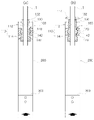
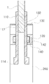
도 2는 본 발명의 일실시예에 따른 시공이 편리한 서스펜션 시스템의 조인트모듈 내부 구조를 나타내는 구성도.
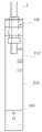
도 3은 본 발명의 일실시예에 따른 시공이 편리한 서스펜션 시스템의 눈금표식부를 나타내는 구성도.
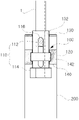
도 4는 본 발명의 일실시예에 따른 시공이 편리한 서스펜션 시스템의 확인구를 나타내는 구성도.
도 5는 본 발명의 일실시예에 따른 시공이 편리한 서스펜션 시스템의 멀티계측모듈을 나타내는 구성도.
도 6은 본 발명의 일실시예에 따른 시공이 편리한 서스펜션 시스템의 멀티계측모듈 사용상태를 나타내는 구성도.
도 7은 본 발명의 일실시예에 따른 시공이 편리한 서스펜션 시스템의 외경수나사부를 나타내는 구성도.
도 8은 본 발명의 일실시예에 따른 시공이 편리한 서스펜션 시스템의 외경수나사부에 의한 행거본체 급속 이동 및 미세 이동 상태를 나타내는 구성도.1 is a configuration diagram showing the overall construction of a convenient suspension system according to an embodiment of the present invention.
Figure 2 is a block diagram showing the internal structure of the joint module of the convenient construction suspension system according to an embodiment of the present invention.
3 is a configuration diagram showing a scale mark of a suspension system for convenient construction according to an embodiment of the present invention.
Figure 4 is a configuration diagram showing a confirmation sphere of a convenient construction suspension system according to an embodiment of the present invention.
5 is a block diagram showing a multi-measurement module of a suspension system for convenient construction according to an embodiment of the present invention.
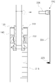
6 is a configuration diagram showing a state in which a multi-measurement module is used in a convenient suspension system according to an embodiment of the present invention;
7 is a configuration diagram illustrating an external male screw part of a suspension system for convenient construction according to an embodiment of the present invention.
8 is a configuration diagram showing the state of rapid movement and fine movement of the hanger body by the external diameter male screw part of the suspension system for convenient construction according to an embodiment of the present invention.
이하에서는 첨부된 도면을 참조하여 본 발명의 실시예들을 상세히 설명하기로 한다.Hereinafter, embodiments of the present invention will be described in detail with reference to the accompanying drawings.
이하, 첨부된 도면을 참조하여 본 발명의 바람직한 실시예를 상세히 설명한다. 그리고 본 발명을 설명함에 있어서 관련된 공지기능에 대하여 이 분야의 기술자들에게 자명한 사항으로서 본 발명의 요지를 불필요하게 흐릴 수 있다고 판단되는 경우에는 그 상세한 설명을 생략한다.Hereinafter, preferred embodiments of the present invention will be described in detail with reference to the accompanying drawings. In the description of the present invention, when it is determined that the subject matter of the present invention may be unnecessarily obscured as it is obvious to those skilled in the art with respect to related known functions, the detailed description thereof will be omitted.
도 1은 본 발명의 일실시예에 따른 시공이 편리한 서스펜션 시스템을 전체적으로 나타내는 구성도이고, 도 2는 본 발명의 일실시예에 따른 시공이 편리한 서스펜션 시스템의 조인트모듈 내부 구조를 나타내는 구성도이며, 도 3은 본 발명의 일실시예에 따른 시공이 편리한 서스펜션 시스템의 눈금표식부를 나타내는 구성도이고, 도 4는 본 발명의 일실시예에 따른 시공이 편리한 서스펜션 시스템의 확인구를 나타내는 구성도이며, 도 5는 본 발명의 일실시예에 따른 시공이 편리한 서스펜션 시스템의 멀티계측모듈을 나타내는 구성도이고, 도 6은 본 발명의 일실시예에 따른 시공이 편리한 서스펜션 시스템의 멀티계측모듈 사용상태를 나타내는 구성도이며, 도 7은 본 발명의 일실시예에 따른 시공이 편리한 서스펜션 시스템의 외경수나사부를 나타내는 구성도이고, 도 8은 본 발명의 일실시예에 따른 시공이 편리한 서스펜션 시스템의 외경수나사부에 의한 행거본체 급속 이동 및 미세 이동 상태를 나타내는 구성도이다.1 is a configuration diagram showing the overall construction of a convenient suspension system according to an embodiment of the present invention, and FIG. 2 is a configuration diagram showing the internal structure of a joint module of a convenient suspension system according to an embodiment of the present invention, 3 is a block diagram showing a scale mark of a suspension system for convenient construction according to an embodiment of the present invention, and FIG. 5 is a block diagram showing a multi-measurement module of a convenient suspension system according to an embodiment of the present invention, and FIG. 7 is a block diagram showing an external male screw part of a convenient suspension system according to an embodiment of the present invention, and FIG. It is a configuration diagram showing the state of rapid movement and fine movement of the hanger body by
본 발명은 시공이 편리한 서스펜션 시스템에 관련되며, 이는 조인트모듈의 너트관체가 행거본체 단부에 자유 회전되도록 구속되어 현장에서 전산볼트와의 조립 시공성이 향상되고, 특히, 너트관체에 형성되는 확인구 및 눈금표식부를 이용하여 행거본체 높낮이 조절에 따른 이동 거리를 정밀하게 검출함과 더불어 행거본체 이동 거리 정보를 이용하여 비숙련공도 쉽게 행거본체들 간에 높낮이 세팅작업을 정밀하게 수행할 수 있도록 조인트모듈(100), 행거본체(200), 거치브라켓(300)을 포함하여 주요구성으로 한다.The present invention relates to a suspension system that is easy to construct, which is restrained so that the nut tube body of the joint module rotates freely at the end of the hanger body to improve assembly workability with the computerized bolt in the field. The joint module (100) is used to precisely detect the movement distance according to the height adjustment of the hanger body using the scale mark and also use the information on the movement distance of the hanger body so that even unskilled workers can easily set the height between the hanger bodies precisely. ), the
본 발명에 따른 조인트모듈(100)은 천장에 연결되는 전산볼트(1)에 나사 체결되어 높낮이 조절되도록 구비된다.The
상기 전산볼트(1)는 수나사봉으로 형성되어 상단부가 건물 천장에 나사 체결방식으로 고정되고, 하단부에 조인트모듈(100)이 설치되는바, 이때 조인트모듈(100)은 후술하는 행거본체(200) 상단부에 설치되어 전산볼트(1)와 나사 체결되도록 구비된다.The computer bolt (1) is formed of a male screw rod, and the upper end is fixed to the ceiling of the building by a screw fastening method, and the
또한, 본 발명에 따른 행거본체(200)는 상기 조인트모듈(100)에 일단이 연결되고, 다른 일단은 하방향으로 연장된다.In addition, one end of the
상기 행거본체(200) 판형 플레이트로 형성되어, 상단에 조인트모듈(100)이 배치되고, 하단에 후술하는 거치브라켓(300)이 구비된다. 이때, 상기 행거본체(200)는 후술하는 거치브라켓(300) 및 조인트모듈(100)의 제 1가이드부(130)와 일체로 절곡 형성된다. 또한, 본 발명에 따른 거치브라켓(300)은 상기 행거본체(200) 하단부에 'ㄴ'자 형태로 절곡되어, 상방향으로 입구가 개방되는 거치홈(320)을 형성한다.The
상기 거치브라켓(300)의 'ㄴ'자형 절곡 구조에 의해 행거본체(200) 하단부에 거치홈(320)이 형성되고, 상기 거치홈(320)은 상방향으로 개방되는 입구를 통하여 천장 마감구조물이 삽입설치된다.A mounting
그리고, 상기 거치브라켓(300) 상부에 핀홀이 형성되고, 핀홀을 통하여 고정핀을 삽입하여 거치홈(320)에 삽입된 천장 마감구조물을 구속하도록 구비된다.And, a pinhole is formed in the upper portion of the mounting
도 2에서, 상기 조인트모듈(100)은, 전산볼트(1)에 나사 체결되도록 암나사부(112)가 형성되고, 외주면 일단에 각형 조인트부(114)가 구비되는 너트관체(110)와, 너트관체(110) 외주면 중앙에 확장 형성되는 가이드링(120)과, 행거본체(200)에 연결되고, 너트관체(110)를 회전가능하게 삽입하는 가이드홀(132)이 형성되는 제 1가이드부(130)와, 행거본체(200)에 연결되고, 제 1가이드부(130)와 이격 배치되어, 내부에 가이드링(120)을 회전가능하게 구속하는 환형 띠홈(142)이 구비되는 제 2가이드부(140)를 포함한다. 이때, 상기 제 2가이드부(140)는 행거본체(200)와 일체형으로 절곡 형성되거나, 별도로 부품으로 제작되어 용접고정된다.In Figure 2, the
그리고, 상기 너트관체(110)의 가이드링(120)이 제 2가이드부(140)의 환형 띠홈(142)에 구속되어, 회전운동은 허용되면서 축선방향 직선 이동은 제한되도록 구비된다.And, the
또, 상기 각형 조인트부(114)는 도 2 (a)와 같이 너트관체(110) 하단부에 형성되거나, 도 2 (b)처럼 너트관체(110) 상, 하단부에 각각 구비하되, 이때 너트관체(110) 상단부에 설치되는 각형 조인트부(114)는 너트관체(110) 외경 대비 작은 사이즈로 형성되어 제 1가이드부(130)의 가이드홀(132)에 관통 삽입 가능하게 구비된다.In addition, the prismatic
이처럼 상기 각형 조인트부(114)가 너트관체(110) 상단부에 배치되어 제 1가이드부(130) 외측으로 노출됨에 따라 주변 간섭없이 공구를 이용한 회전 조작이 용이하여 현정 작업성이 향상된다. As such, as the square
이에 상기 각형 조인트부(114)에 공구를 체결하여 너트관체(110)를 회전시, 너트관체(110)가 제 1, 2가이드부(130)(140)에 구속된 상태로 암나사부(112)와 전산볼트(1) 간에 피치 이송으로 인해 행거본체(200)가 전산볼트(1) 길이방향으로 이동되면서 높낮이 조절되도록 구비된다.Accordingly, when the
도 3에서, 상기 행거본체(200)에 길이방향으로 눈금표식부(210)가 형성된다.In FIG. 3 , a
그리고, 상기 눈금포식부(210)를 기준으로 전산볼트(1) 위치를 확인하여 행거본체(200) 이동 거리를 수치데이터로 검출하도록 구비된다.And, it is provided to determine the position of the computer bolt (1) based on the
즉, 상기 너트관체(110)에 나사 체결된 전산볼트(1) 단부가 행거본체(200) 전면으로 노출되면, 눈금포식부(210)를 기준으로 전산볼트(1) 위치를 육안으로 확인하여 행거본체(200) 높낮이 조절에 따른 이동 거리를 정밀하게 검출할 수 있고, 이러한 행거본체(200) 이동 거리 정보를 이용하여 비숙련공도 쉽게 행거본체(200) 높낮이 세팅작업을 정밀하게 수행할 수 있는 이점이 있다.That is, when the end of the computerized bolt (1) screwed to the nut tube body (110) is exposed to the front of the hanger body (200), the position of the computerized bolt (1) is visually confirmed based on the scale predation part (210) and hanger It is possible to precisely detect the movement distance according to the height adjustment of the
도 4에서, 상기 너트관체(110) 길이 방향으로 확인구(116)가 형성된다. 상기 확인구(116)는 암나사부(112) 내에 나사 체결된 전산볼트(1)를 너트관체(110) 외부에서 식별할 수 있도록 구비된다.In FIG. 4 , a
즉, 상기 확인구(116)는 장공형으로 절개되고, 확인구(116)를 통하여 암나사부(112) 내부가 노출됨에 따라 너트관체(110)를 전산볼트(1)에 나사 체결시, 전산볼트(1) 나사 체결 위치가 확인구(116)를 통하여 육안으로 검출되어 전산볼트(1)의 나사 체결 깊이를 검사하여 시공 안전성을 판단하는 중요한 정보로 이용할 수 있다.That is, the
도 5에서, 상기 행거본체(200)는 멀티계측모듈(220)에 의해 너트관체(110)의 피치 이송에 의한 이동 거리가 검출되도록 구비된다.In FIG. 5 , the
상기 멀티계측모듈(220)은, 눈금표식부(210)와 대응하는 제 1, 2가이드부(130)(140)에 측면에 함몰 형성되는 로드홈(222)과, 로드홈(222)에 삽입되고, 하단부에 눈금표식부(210)와 겹침 배치되는 계측바늘(223)이 구비되는 로드봉(224)과, 로드봉(224) 상단부에 설치되어 전산볼트(1)에 클램핑되는 집게(226)를 포함한다.The
이때, 상기 로드홈(222)은 로드봉(224)의 직선 이동을 안내하는 레일 기능을 수행하고, 상기 로드봉(224)은 집게(226)에 의해 전산볼트(1)에 장착되어 로드홈(222)을 타고 전산볼트(1)와 함께 직선 이동되도록 구비된다.At this time, the
상기 멀티계측모듈(220)을 이용한 행거본체(200) 이동 거리 정보 추출 방법을 살펴보면, 도 6 (a)처럼 상기 너트관체(110)를 전산볼트(1)에 나사 체결하여 행거본체(200)를 가조립하고, 멀티계측모듈(220)의 계측바늘(223)이 눈금표식부(210) 영역에 위치되는 지점에서 집게(226)를 이용하여 로드봉(224)을 전산볼트(1)에 체결하여 기준점을 설정한다.Looking at the method of extracting information on the movement distance of the
이후, 도 6 (b)와 같이, 상기 너트관체(110)의 회전력에 의해 행거본체(200)가 상하 방향으로 피치 이동시, 계측바늘(223)을 기준으로 눈금표식부(210) 변위량을 측정하여 행거본체(200)의 이동 거리를 검출하도록 구비된다.Thereafter, as shown in FIG. 6 (b), when the
그리고, 상기 행거본체(200)의 이동 거리 검출 및 높낮이 세팅이 완료되면, 집게(226)를 언클램핑한 후 로드봉(224)을 회수하여 다른 위치에서 재사용하도록 구비된다. And, when the movement distance detection and height setting of the
이처럼 상기 전산볼트(1)에 연결되는 로드봉(224)에 의해 행거본체(200)의 이동 거리가 검출됨에 따라 전산볼트(1) 단부가 너트관체(110) 내에 위치되어 외부에서 식별할 수 없는 경우에도 로드봉(224)의 계측바늘(223)을 기준으로 눈금표식부(210) 변위량을 측정하여 행거본체(200)의 이동 거리를 정밀 측정할 수 있는 이점이 있다.As such, as the moving distance of the
도 7에서, 상기 너트관체(110)와 가이드링(120)은 분할 형성되어 외경수나사부(150)에 의해 나사 체결되고, 상기 외경수나사부(150)는 너트관체(110)의 암나사부(112)와 반대 방향 나사로 형성된다.In FIG. 7 , the
이에 도 8 (a)와 같이, 상기 행거본체(200)를 하중에 의해 가이드링(120)과 환형 띠홈(142) 간에 밀착하중이 가해진 상태로 너트관체(110)를 회전시, 가이드링(120)이 정지된 상태로 너트관체(110)가 외경수나사부(150)와 피치 이송됨과 동시에 암나사부(112)와 전산볼트(1) 간에 피치 이송되면서 행거본체(200)가 전산볼트(1) 길이방향으로 급속 이동되어 초기 신속한 위치 조절이 가능하다.Accordingly, as shown in Fig. 8 (a), when the
그리고, 도 8 (b)처럼, 상기 행거본체(200)를 상방향으로 들어올려 가이드링(120)과 환형 띠홈(142) 간에 밀착하중이 해제된 상태로 너트관체(110)를 회전시, 가이드링(120)이 너트관체(110)와 함께 환형 띠홈(142) 내에서 자유 회전되면서 암나사부(112)와 전산볼트(1) 간에 피치 이송으로 인해 행거본체(200)가 전산볼트(1) 길이방향으로 미세 이동되도록 구비되므로, 정밀한 높낮이 설정이 가능하게 된다.And, as shown in Fig. 8 (b), when the
이상과 같이 본 발명은 비록 한정된 실시예와 도면에 의해 설명되었으나, 본 발명은 상기의 실시예에 한정되는 것은 아니며, 이는 본 발명이 속하는 분야에서 통상의 지식을 가진 자라면 이러한 기재로부터 다양한 수정 및 변형이 가능하다. 따라서, 본 발명 사상은 아래에 기재된 특허청구범위에 의해서만 파악되어야 하고, 이의 균등 또는 등가적 변형 모두는 본 발명 사상의 범주에 속한다고 할 것이다.As described above, although the present invention has been described with reference to the limited embodiments and drawings, the present invention is not limited to the above embodiments, which are various modifications and Transformation is possible. Accordingly, the spirit of the present invention should be understood only by the claims described below, and all equivalents or equivalent modifications thereof will fall within the scope of the spirit of the present invention.
한편 본 명세서에 개시된 기술에 관한 설명은 단지 구조적 내지 기능적 설명을 위한 실시예에 불과하므로, 개시된 기술의 권리범위는 본문에 설명된 실시예에 의하여 제한되는 것으로 해석되어서는 아니 된다. 즉, 실시예는 다양한 변경이 가능하고 여러 가지 형태를 가질 수 있으므로 개시된 기술의 권리범위는 기술적 사상을 실현할 수 있는 균등물들을 포함하는 것으로 이해되어야 한다. 또한, 개시된 기술에서 제시된 목적 또는 효과는 특정 실시예가 이를 전부 포함하여야 한다거나 그러한 효과만을 포함하여야 한다는 의미는 아니므로, 개시된 기술의 권리범위는 이에 의하여 제한되는 것으로 이해되어서는 아니 될 것이다.Meanwhile, since the description of the technology disclosed in the present specification is merely an embodiment for structural or functional description, the scope of the disclosed technology should not be construed as being limited by the embodiment described in the text. That is, since the embodiment may have various changes and may have various forms, it should be understood that the scope of the disclosed technology includes equivalents capable of realizing the technical idea. In addition, since the object or effect presented in the disclosed technology does not mean that a specific embodiment should include all of them or only such effects, it should not be understood that the scope of the disclosed technology is limited thereby.
또한 본 발명에서 서술되는 용어의 의미는 다음과 같이 이해되어야 할 것이다. “제1”, “제2” 등의 용어는 하나의 구성요소를 다른 구성요소로부터 구별하기 위한 것으로, 이들 용어들에 의해 권리범위가 한정되어서는 아니 된다. 예를 들어, 제1 구성요소는 제2 구성요소로 명명될 수 있고, 유사하게 제2 구성요소로 제1 구성요소로 명명될 수 있다.In addition, the meaning of the terms described in the present invention should be understood as follows. Terms such as “first” and “second” are for distinguishing one component from other components, and the scope of rights should not be limited by these terms. For example, a first component may be termed a second component, and similarly a second component may be termed a first component.
나아가 어떤 구성요소가 다른 구성요소에 “연결되어”있다고 언급된 때에는, 그 다른 구성요소에 직접적으로 연결될 수도 있지만, 중간에 다른 구성요소가 존재할 수도 있다고 이해되어야 할 것이다. 반면에, 어떤 구성요소가 다른 구성요소에 “직접 연결되어”있다고 언급된 때에는 중간에 다른 구성요소가 존재하지 않는 것으로 이해되어야 할 것이다. 한편, 구성요소들 간의 관계를 설명하는 다른 표현들, 즉 “~사이에”와 “~사이에” 또는 “~에 이웃하는”과 “~에 직접 이웃하는” 등도 마찬가지로 해석되어야 한다.Furthermore, when it is mentioned that a certain element is "connected" to another element, it may be directly connected to the other element, but it should be understood that other elements may exist in between. On the other hand, when it is mentioned that a certain element is "directly connected" to another element, it should be understood that the other element does not exist in the middle. On the other hand, other expressions describing the relationship between elements, that is, “between” and “between” or “neighboring to” and “directly adjacent to”, etc., should be interpreted similarly.
단수의 표현은 문맥상 명백하게 다르게 뜻하지 않는 한 복수의 표현을 포함하는 것으로 이해되어야 하고, “포함하다”또는 “가지다” 등의 용어는 설시된 특징, 숫자, 단계, 동작, 구성요소, 부분품 또는 이들을 조합한 것이 존재함을 지정하려는 것이며, 하나 또는 그 이상의 다른 특징이나 숫자, 단계, 동작, 구성요소, 부분품 또는 이들을 조합한 것들의 존재 또는 부가 가능성을 미리 배제하지 않는 것으로 이해되어야 한다.The singular expression is to be understood as including the plural expression unless the context clearly dictates otherwise, and terms such as “comprises” or “have” refer to the specified feature, number, step, action, component, part or these It is intended to indicate that a combination exists, and it should be understood that it does not preclude the possibility of the existence or addition of one or more other features or numbers, steps, operations, components, parts, or combinations thereof.
100 : 지지틀
110 : 격자
120 : 충전재
130 : 제1 세로대
140 : 내측벽체 부
150 : 판재
160 : 외측벽체 부
200 : 벽체 연결 판재100: support frame 110: grid
120: filling material 130: first vertical bar
140: inner wall part 150: plate material
160: outer wall part 200: wall connection plate
Claims (5)
상기 조인트모듈(100)에 일단이 연결되고, 다른 일단은 하방향으로 연장되는 행거본체(200); 및
상기 행거본체(200) 하단부에 'ㄴ'자 형태로 절곡되어, 상방향으로 입구가 개방되는 거치홈(320)을 형성하는 거치브라켓(300);을 포함하는 것을 특징으로 하는 시공이 편리한 서스펜션 시스템.
The joint module 100 is screwed to the computer bolt (1) connected to the ceiling and provided to adjust the height;
a hanger body 200 having one end connected to the joint module 100 and the other end extending in the downward direction; and
The hanger body 200 is bent in a 'L' shape at the lower end of the mount bracket 300 to form a mounting groove 320 that opens the entrance in the upward direction; .
상기 조인트모듈(100)은 전산볼트(1)에 나사 체결되도록 암나사부(112)가 형성되고, 외주면 일단에 각형 조인트부(114)가 구비되는 너트관체(110)와,
너트관체(110) 외주면 중앙에 확장 형성되는 가이드링(120)과,
행거본체(200)에 연결되고, 너트관체(110)를 회전가능하게 삽입하는 가이드홀(132)이 형성되는 제 1가이드부(130)와,
행거본체(200)에 연결되고, 제 1가이드부(130)와 이격 배치되어, 내부에 가이드링(120)을 회전가능하게 구속하는 환형 띠홈(142)이 구비되는 제 2가이드부(140)를 포함하는 것을 특징으로 하는 시공이 편리한 서스펜션 시스템.
The method of claim 1,
The joint module 100 includes a nut tube body 110 having a female screw part 112 formed so as to be screwed to the computerized bolt 1, and having a square joint part 114 at one end of the outer circumferential surface;
A guide ring 120 that is extended and formed in the center of the outer peripheral surface of the nut tube body 110,
A first guide portion 130 connected to the hanger body 200 and having a guide hole 132 for rotatably inserting the nut tube body 110 is formed therein;
The second guide part 140 is connected to the hanger body 200, is spaced apart from the first guide part 130, and is provided with an annular band groove 142 for rotatably constraining the guide ring 120 therein. Easy-to-construct suspension system, characterized in that it includes.
상기 각형 조인트부(114)는 공구에 체결되어 너트관체(110)를 회전시, 너트관체(110)가 제 1, 2가이드부(130)(140)에 구속된 상태로 암나사부(112)와 전산볼트(1) 간에 피치 이송으로 인해 행거본체(200)가 전산볼트(1) 길이방향으로 이동되면서 높낮이 조절되도록 구비되는 것을 특징으로 하는 시공이 편리한 서스펜션 시스템.
3. The method of claim 2,
The prismatic joint part 114 is fastened to the tool to rotate the nut tube body 110, the nut tube body 110 is constrained to the first and second guide parts 130 and 140, and the Suspension system for convenient construction, characterized in that the hanger body 200 is moved in the longitudinal direction of the computerized bolts (1) due to pitch transfer between the computerized bolts (1) and is provided to adjust the height.
상기 행거본체(200)에 길이방향으로 눈금표식부(210)가 형성되고, 상기 눈금포식부(210)를 기준으로 전산볼트(1) 위치를 확인하여 행거본체(200) 이동 거리를 수치데이터로 검출하도록 구비되는 것을 특징으로 하는 시공이 편리한 서스펜션 시스템.
3. The method of claim 1 or 2,
A scale mark 210 is formed on the hanger body 200 in the longitudinal direction, and the position of the computerized bolt 1 is checked based on the scale engraving part 210, and the hanger body 200 moving distance is converted to numerical data. Easy-to-construct suspension system, characterized in that it is provided to detect.
상기 너트관체(110) 길이 방향으로 확인구(116)가 형성되고, 상기 확인구(116)는 암나사부(112) 내에 나사 체결된 전산볼트(1)를 너트관체(110) 외부에서 식별할 수 있도록 구비되는 것을 특징으로 하는 시공이 편리한 서스펜션 시스템.
3. The method of claim 2,
The confirmation hole 116 is formed in the longitudinal direction of the nut tube body 110, and the confirmation hole 116 can identify the computerized bolt 1 screwed in the female thread part 112 from the outside of the nut tube body 110. Suspension system for convenient construction, characterized in that it is provided so that
Applications Claiming Priority (2)
| Application Number | Priority Date | Filing Date | Title |
|---|---|---|---|
| KR20210018658 | 2021-02-09 | ||
| KR1020210018658 | 2021-02-09 |
Publications (2)
| Publication Number | Publication Date |
|---|---|
| KR20220115026A true KR20220115026A (en) | 2022-08-17 |
| KR102553618B1 KR102553618B1 (en) | 2023-07-10 |
Family
ID=83110892
Family Applications (1)
| Application Number | Title | Priority Date | Filing Date |
|---|---|---|---|
| KR1020210070323A Active KR102553618B1 (en) | 2021-02-09 | 2021-05-31 | Easy to construction suspension system |
Country Status (1)
| Country | Link |
|---|---|
| KR (1) | KR102553618B1 (en) |
Cited By (1)
| Publication number | Priority date | Publication date | Assignee | Title |
|---|---|---|---|---|
| CN116498105A (en) * | 2023-06-13 | 2023-07-28 | 湖北福鑫重型钢结构工程股份有限公司 | A kind of steel structure safety rope suspension device and using method |
Citations (8)
| Publication number | Priority date | Publication date | Assignee | Title |
|---|---|---|---|---|
| JP2000130644A (en) * | 1998-10-28 | 2000-05-12 | Showa Corporation:Kk | Suspension tools |
| KR200388553Y1 (en) * | 2005-04-20 | 2005-06-29 | 김권희 | Fixing hanger for ceiling pannel |
| JP3126730U (en) * | 2006-07-06 | 2006-11-09 | 祐史 村瀬 | Free hole hanger |
| KR100865088B1 (en) | 2007-10-25 | 2008-10-23 | 김남영 | Hanger for fixing ceiling panel |
| KR100979167B1 (en) | 2009-02-24 | 2010-08-31 | 주식회사 대한강재 | hanger |
| KR101048643B1 (en) * | 2011-05-13 | 2011-07-15 | 이한욱 | Ceiling panel fixture |
| KR101973319B1 (en) | 2018-04-20 | 2019-04-29 | (주)유창 | High strength hanger for clamping ceiling frame |
| KR20190119570A (en) * | 2018-04-11 | 2019-10-22 | 정민시 | Ceiling structure with increased workability and space utilization and construction method |
-
2021
- 2021-05-31 KR KR1020210070323A patent/KR102553618B1/en active Active
Patent Citations (8)
| Publication number | Priority date | Publication date | Assignee | Title |
|---|---|---|---|---|
| JP2000130644A (en) * | 1998-10-28 | 2000-05-12 | Showa Corporation:Kk | Suspension tools |
| KR200388553Y1 (en) * | 2005-04-20 | 2005-06-29 | 김권희 | Fixing hanger for ceiling pannel |
| JP3126730U (en) * | 2006-07-06 | 2006-11-09 | 祐史 村瀬 | Free hole hanger |
| KR100865088B1 (en) | 2007-10-25 | 2008-10-23 | 김남영 | Hanger for fixing ceiling panel |
| KR100979167B1 (en) | 2009-02-24 | 2010-08-31 | 주식회사 대한강재 | hanger |
| KR101048643B1 (en) * | 2011-05-13 | 2011-07-15 | 이한욱 | Ceiling panel fixture |
| KR20190119570A (en) * | 2018-04-11 | 2019-10-22 | 정민시 | Ceiling structure with increased workability and space utilization and construction method |
| KR101973319B1 (en) | 2018-04-20 | 2019-04-29 | (주)유창 | High strength hanger for clamping ceiling frame |
Cited By (1)
| Publication number | Priority date | Publication date | Assignee | Title |
|---|---|---|---|---|
| CN116498105A (en) * | 2023-06-13 | 2023-07-28 | 湖北福鑫重型钢结构工程股份有限公司 | A kind of steel structure safety rope suspension device and using method |
Also Published As
| Publication number | Publication date |
|---|---|
| KR102553618B1 (en) | 2023-07-10 |
Similar Documents
| Publication | Publication Date | Title |
|---|---|---|
| WO2020143222A1 (en) | Fabricated suspended ceiling structure and installation method therefor | |
| KR20180128905A (en) | Method and mounting device for performing installation work on a lift shaft of a lift system | |
| US20130320157A1 (en) | Utility conduit supporting device, system, and method | |
| CN112875504B (en) | Hanger rail device facilitating installation | |
| KR102553618B1 (en) | Easy to construction suspension system | |
| CN202706308U (en) | Clamping slot type light steel keel suspension structure | |
| JP4884269B2 (en) | How to install the precast concrete waist wall | |
| CN201723942U (en) | Support for mounting security protection device | |
| JP5940322B2 (en) | Pillar fixture | |
| CN219219486U (en) | Adjustable back bolt mounting structure of special-shaped curtain wall | |
| CN203716364U (en) | Curtain wall support and curtain wall system | |
| JP3955511B2 (en) | Cable erection device | |
| CN213141181U (en) | Mounting member for facilitating installation | |
| US20040055230A1 (en) | Anchoring bracket | |
| KR100865991B1 (en) | Scaffolding Pipe Mounting Clamps | |
| CN112746693B (en) | Wall panel connection nodes and buildings | |
| CN205369624U (en) | Disconnect -type adaptor | |
| KR20140002928U (en) | Beam clamp | |
| JP4606957B2 (en) | Fire alarm fitting | |
| JP4332896B2 (en) | Foundation concrete reinforcement method | |
| TWI873026B (en) | Steel frame connection component system | |
| KR102840875B1 (en) | Apparatus for Installing a Washbasin | |
| CN212106574U (en) | A pre-buried mounting for hoist and mount | |
| CN216344346U (en) | Combined pipeline angle steel bracket for controlling vertical pipe installation verticality | |
| CN212154220U (en) | Fixing device for edge guard rail |
Legal Events
| Date | Code | Title | Description |
|---|---|---|---|
| PA0109 | Patent application |
St.27 status event code: A-0-1-A10-A12-nap-PA0109 |
|
| PA0201 | Request for examination |
St.27 status event code: A-1-2-D10-D11-exm-PA0201 |
|
| P11-X000 | Amendment of application requested |
St.27 status event code: A-2-2-P10-P11-nap-X000 |
|
| P13-X000 | Application amended |
St.27 status event code: A-2-2-P10-P13-nap-X000 |
|
| D13-X000 | Search requested |
St.27 status event code: A-1-2-D10-D13-srh-X000 |
|
| D14-X000 | Search report completed |
St.27 status event code: A-1-2-D10-D14-srh-X000 |
|
| PG1501 | Laying open of application |
St.27 status event code: A-1-1-Q10-Q12-nap-PG1501 |
|
| E902 | Notification of reason for refusal | ||
| PE0902 | Notice of grounds for rejection |
St.27 status event code: A-1-2-D10-D21-exm-PE0902 |
|
| P11-X000 | Amendment of application requested |
St.27 status event code: A-2-2-P10-P11-nap-X000 |
|
| P13-X000 | Application amended |
St.27 status event code: A-2-2-P10-P13-nap-X000 |
|
| E701 | Decision to grant or registration of patent right | ||
| PE0701 | Decision of registration |
St.27 status event code: A-1-2-D10-D22-exm-PE0701 |
|
| GRNT | Written decision to grant | ||
| PR0701 | Registration of establishment |
St.27 status event code: A-2-4-F10-F11-exm-PR0701 |
|
| PR1002 | Payment of registration fee |
St.27 status event code: A-2-2-U10-U11-oth-PR1002 Fee payment year number: 1 |
|
| PG1601 | Publication of registration |
St.27 status event code: A-4-4-Q10-Q13-nap-PG1601 |
|
| PN2301 | Change of applicant |
St.27 status event code: A-5-5-R10-R13-asn-PN2301 St.27 status event code: A-5-5-R10-R11-asn-PN2301 |
|
| R18-X000 | Changes to party contact information recorded |
St.27 status event code: A-5-5-R10-R18-oth-X000 |
|
| PN2301 | Change of applicant |
St.27 status event code: A-5-5-R10-R13-asn-PN2301 St.27 status event code: A-5-5-R10-R11-asn-PN2301 |
|
| PR1001 | Payment of annual fee |
St.27 status event code: A-4-4-U10-U11-oth-PR1001 Fee payment year number: 4 |
|
| U11 | Full renewal or maintenance fee paid |
Free format text: ST27 STATUS EVENT CODE: A-4-4-U10-U11-OTH-PR1001 (AS PROVIDED BY THE NATIONAL OFFICE) Year of fee payment: 4 |