KR20210141177A - Device for Adjusting Height of Sliding Roller - Google Patents
Device for Adjusting Height of Sliding Roller Download PDFInfo
- Publication number
- KR20210141177A KR20210141177A KR1020200058500A KR20200058500A KR20210141177A KR 20210141177 A KR20210141177 A KR 20210141177A KR 1020200058500 A KR1020200058500 A KR 1020200058500A KR 20200058500 A KR20200058500 A KR 20200058500A KR 20210141177 A KR20210141177 A KR 20210141177A
- Authority
- KR
- South Korea
- Prior art keywords
- plate
- bracket
- groove
- block
- height adjustment
- Prior art date
- Legal status (The legal status is an assumption and is not a legal conclusion. Google has not performed a legal analysis and makes no representation as to the accuracy of the status listed.)
- Granted
Links
Images










Classifications
-
- E—FIXED CONSTRUCTIONS
- E05—LOCKS; KEYS; WINDOW OR DOOR FITTINGS; SAFES
- E05D—HINGES OR SUSPENSION DEVICES FOR DOORS, WINDOWS OR WINGS
- E05D15/00—Suspension arrangements for wings
- E05D15/06—Suspension arrangements for wings for wings sliding horizontally more or less in their own plane
- E05D15/0621—Details, e.g. suspension or supporting guides
- E05D15/066—Details, e.g. suspension or supporting guides for wings supported at the bottom
- E05D15/0665—Details, e.g. suspension or supporting guides for wings supported at the bottom on wheels with fixed axis
- E05D15/0669—Details, e.g. suspension or supporting guides for wings supported at the bottom on wheels with fixed axis with height adjustment
-
- E—FIXED CONSTRUCTIONS
- E05—LOCKS; KEYS; WINDOW OR DOOR FITTINGS; SAFES
- E05Y—INDEXING SCHEME ASSOCIATED WITH SUBCLASSES E05D AND E05F, RELATING TO CONSTRUCTION ELEMENTS, ELECTRIC CONTROL, POWER SUPPLY, POWER SIGNAL OR TRANSMISSION, USER INTERFACES, MOUNTING OR COUPLING, DETAILS, ACCESSORIES, AUXILIARY OPERATIONS NOT OTHERWISE PROVIDED FOR, APPLICATION THEREOF
- E05Y2201/00—Constructional elements; Accessories therefor
- E05Y2201/60—Suspension or transmission members; Accessories therefor
- E05Y2201/622—Suspension or transmission members elements
- E05Y2201/688—Rollers
-
- E—FIXED CONSTRUCTIONS
- E05—LOCKS; KEYS; WINDOW OR DOOR FITTINGS; SAFES
- E05Y—INDEXING SCHEME ASSOCIATED WITH SUBCLASSES E05D AND E05F, RELATING TO CONSTRUCTION ELEMENTS, ELECTRIC CONTROL, POWER SUPPLY, POWER SIGNAL OR TRANSMISSION, USER INTERFACES, MOUNTING OR COUPLING, DETAILS, ACCESSORIES, AUXILIARY OPERATIONS NOT OTHERWISE PROVIDED FOR, APPLICATION THEREOF
- E05Y2600/00—Mounting or coupling arrangements for elements provided for in this subclass
- E05Y2600/60—Mounting or coupling members; Accessories therefor
- E05Y2600/632—Screws
-
- E—FIXED CONSTRUCTIONS
- E05—LOCKS; KEYS; WINDOW OR DOOR FITTINGS; SAFES
- E05Y—INDEXING SCHEME ASSOCIATED WITH SUBCLASSES E05D AND E05F, RELATING TO CONSTRUCTION ELEMENTS, ELECTRIC CONTROL, POWER SUPPLY, POWER SIGNAL OR TRANSMISSION, USER INTERFACES, MOUNTING OR COUPLING, DETAILS, ACCESSORIES, AUXILIARY OPERATIONS NOT OTHERWISE PROVIDED FOR, APPLICATION THEREOF
- E05Y2900/00—Application of doors, windows, wings or fittings thereof
- E05Y2900/10—Application of doors, windows, wings or fittings thereof for buildings or parts thereof
- E05Y2900/13—Type of wing
- E05Y2900/132—Doors
Landscapes
- Engineering & Computer Science (AREA)
- Mechanical Engineering (AREA)
- Support Devices For Sliding Doors (AREA)
Abstract
본 발명은 슬라이딩 롤러 높이 조절 장치에 관한 것으로써, 슬라이딩 도어가 설치되는 저장공간에 있어서, 상기 저장공간에 설치되는 레일 프레임과, 상기 레일 프레임과 마주보도록 상기 슬라이딩 도어에 설치되는 지지 브라켓과, 상기 지지 브라켓에 높이방향으로 이동 가능하게 설치되는 조절 브라켓을 포함하는 슬라이딩 롤러와, 상기 레일 프레임에 걸쳐져 이동되도록 상기 조절 브라켓에 설치되는 바퀴와, 상기 조절 브라켓이 설치되는 방향으로 절곡되게 상기 지지 브라켓의 상부에 형성되는 지지판과, 상기 지지판 상부에 형성되는 요홈과, 상기 조절 브라켓에 고정되고, 상기 요홈에 삽입되어 상기 지지판에 걸쳐지는 블록 및 상기 블록에 나사결합되어, 회전방향에 따라 상기 지지 브라켓에 대한 상기 블록의 높낮이를 조절하는 높이조절나사를 포함하여 상기 슬라이딩 롤러의 높이를 조절할 때 상기 슬라이딩 롤러의 견고성을 향상시킨 슬라이딩 롤러 높이 조절 장치에 관한 발명이다.The present invention relates to a sliding roller height adjustment device, wherein in a storage space in which a sliding door is installed, a rail frame installed in the storage space, a support bracket installed in the sliding door to face the rail frame, and the A sliding roller including an adjustment bracket movably installed on the support bracket in the height direction, a wheel installed on the adjustment bracket to move across the rail frame, and a support bracket to be bent in the direction in which the adjustment bracket is installed A support plate formed on an upper portion, a groove formed on the upper portion of the support plate, a block fixed to the adjustment bracket, inserted into the groove and spanning the support plate, and screwed to the block, the support bracket according to the rotational direction The present invention relates to a sliding roller height adjustment device that improves the rigidity of the sliding roller when adjusting the height of the sliding roller, including a height adjustment screw for adjusting the height of the block.
Description
본 발명은 슬라이딩 도어가 설치되는 저장공간에 있어서, 일측은 상기 슬라이딩 도어에 설치되고, 타측은 상기 저장공간의 레일 프레임에 설치되는 슬라이딩 롤러의 높이를 조절하여, 상기 슬라이딩 도어와 상기 레일 프레임 간의 높이차를 조절할 수 있는 슬라이딩 롤러 높이 조절 장치에 관한 것이다.According to the present invention, in a storage space in which a sliding door is installed, one side is installed on the sliding door, and the other side adjusts the height of a sliding roller installed on a rail frame of the storage space to adjust the height between the sliding door and the rail frame. It relates to a sliding roller height adjustment device capable of adjusting a car.
도 1 내지 도 2에 도시된 바와 같이, 슬라이딩 도어(30,40)가 설치되는 저장공간(20)에 있어서, 저장공간(20)의 상단에는 레일 프레임(50)이 설치되고, 슬라이딩 도어(30,40)의 상단에는 레일 프레임(50)과 마주보도록 슬라이딩 롤러(1000,2000)가 설치된다. 1 to 2, in the
레일 프레임(50)에 걸쳐지도록 형성되는 바퀴(1150,2110)가 슬라이딩 롤러(1000,2000)에 설치된다. 이로써 슬라이딩 도어(30,40)와 레일 프레임(50)이 연결되어, 슬라이딩 도어(30,40)는 레일 프레임(50)을 따라 이동되며 열리거나 닫힌다.
저장공간(20)은 붙박이장, 옷장, 서랍 등일 수 있다.The
이 때, 슬라이딩 도어(30,40)의 처짐 현상으로 슬라이딩 도어(30,40)의 높낮이가 안 맞는 문제점이 있다.At this time, there is a problem that the height of the sliding
이러한 문제를 해결하기 위한 종래의 기술이 '한국등록특허공보 제10-1912146호'에 제시되어 있다.A conventional technique for solving this problem is presented in 'Korea Patent Publication No. 10-1912146'.
'한국등록특허공보 제10-1912146호'의 슬라이딩 도어용 맞춤구는 레일 상에서 구름 운동하는 최소한 하나의 트랙 롤러가 설치된 트랙 롤러 캐리어와, 슬라이딩 도어에 고정되는 지지 부재를 구비하며, 나선 스핀들은 상기 지지 부재의 나선 내부에 회전가능하게 설치되어 높이를 조절하고, 상기 지지부재는 적어도 부분적으로 상기 트랙 롤러 캐리어의 U자형 요홈 내부로 삽입되고, 상기 나선 스핀들은 상기 요홈 기저부 상에 지지된다.The fitting tool for sliding door of 'Korea Patent Publication No. 10-1912146' includes a track roller carrier installed with at least one track roller that rolls on a rail, and a support member fixed to the sliding door, and the spiral spindle supports the support. It is rotatably mounted within the spiral of the member to adjust the height, the support member is at least partially inserted into the U-shaped recess of the track roller carrier, and the spiral spindle is supported on the bottom of the recess.
이러한 슬라이딩 도어용 맞춤구는 다음과 같은 문제가 있다.The fittings for these sliding doors have the following problems.
상기 U자형 요홈이 판으로 형성되는 상기 트랙 롤러 캐리어에 형성되므로, 상기 U자형 요홈의 기저부의 폭은 상기 판의 두께와 동일하다. 그로므로 상기 U자형 요홈의 기저부는 단면적이 좁아지고, 상기 스핀들을 지지할 때 견고성이 감소하게 된다.Since the U-shaped groove is formed in the track roller carrier formed of a plate, the width of the base of the U-shaped groove is equal to the thickness of the plate. Therefore, the cross-sectional area of the base of the U-shaped groove is narrowed, and the rigidity when supporting the spindle is reduced.
본 발명은 전술한 문제점을 해결하기 위하여 안출된 것으로, 슬라이딩 도어가 설치되는 저장공간에 있어서, 슬라이딩 도어에 설치되는 지지 브라켓과, 상기 저장공간에 설치되는 레일 프레임에 걸쳐지는 바퀴가 설치되는 조절 브라켓 사이의 높이차를, 상기 조절 브라켓에 설치되며 상기 지지 브라켓에 지지되는 블록을 이용해서 조절할 때, 상기 지지 브라켓의 일부를 절곡시켜 상기 블록이 올라갈 수 있는 지지판을 형성하는 슬라이딩 롤러 높이조절 장치를 제공하는 데 그 목적이 있다.The present invention has been devised to solve the above-mentioned problems, and in a storage space in which a sliding door is installed, a support bracket installed in the sliding door and an adjustment bracket in which a wheel spanning a rail frame installed in the storage space is installed. When adjusting the height difference between the adjustment brackets using a block installed in the adjustment bracket and supported by the support bracket, a sliding roller height adjustment device is provided that forms a support plate on which the block can climb by bending a part of the support bracket It is intended to
전술한 목적을 달성하기 위한 본 발명의 슬라이딩 롤러 높이 조절 장치는, 슬라이딩 도어가 설치되는 저장공간에 있어서, 상기 저장공간에 설치되는 레일 프레임과, 상기 레일 프레임과 마주보도록 상기 슬라이딩 도어에 설치되는 지지 브라켓과, 상기 지지 브라켓에 높이방향으로 이동 가능하게 설치되는 조절 브라켓을 포함하는 슬라이딩 롤러와, 상기 레일 프레임에 걸쳐져 이동되도록 상기 조절 브라켓에 설치되는 바퀴와, 상기 조절 브라켓이 설치되는 방향으로 절곡되게 상기 지지 브라켓의 상부에 형성되는 지지판과, 상기 지지판 상부에 형성되는 요홈과, 상기 조절 브라켓에 고정되고, 상기 요홈에 삽입되어 상기 지지판에 걸쳐지는 블록 및 상기 블록에 나사결합되어, 회전방향에 따라 상기 지지 브라켓에 대한 상기 블록의 높낮이를 조절하는 높이조절나사를 포함한다.The sliding roller height adjusting device of the present invention for achieving the above object, in a storage space in which a sliding door is installed, a rail frame installed in the storage space, and a support installed in the sliding door to face the rail frame A sliding roller comprising a bracket, an adjustment bracket movably installed on the support bracket in a height direction, a wheel installed on the adjustment bracket to move across the rail frame, and bent in a direction in which the adjustment bracket is installed A support plate formed on the upper portion of the support bracket, a groove formed on the upper portion of the support plate, a block fixed to the adjustment bracket, inserted into the groove and spanning the support plate, and screwed to the block, depending on the rotational direction and a height adjusting screw for adjusting the height of the block with respect to the support bracket.
상기 지지 브라켓에는 높이방향으로 슬롯이 형성되고, 나사가 상기 슬롯을 통해 상기 조절 브라켓에 결합되어, 상기 나사가 상기 슬롯에 높이방향으로 슬라이딩 될 수 있다.A slot is formed in the support bracket in a height direction, and a screw is coupled to the adjustment bracket through the slot, so that the screw can be slid in the slot in the height direction.
상기 지지 브라켓은 상기 슬라이딩 도어 상부의 양측 모서리에 설치되고, 상기 지지 브라켓은 상기 모서리의 형상에 맞게 형성되는 수직판과 수평판을 포함하여 L자 형태로 형성되고, 상기 수직판은 상기 조절 브라켓의 이동경로를 제한하는 방향으로 돌출되게 형성될 수 있다.The support brackets are installed on both corners of the upper portion of the sliding door, and the support brackets are formed in an L-shape including a vertical plate and a horizontal plate that are formed to fit the shape of the corner, and the vertical plate is the control bracket. It may be formed to protrude in a direction limiting the movement path.
상기 지지 브라켓에는 상기 블록이 설치되는 방향으로 절곡되게 블록 걸림판이 형성되어, 상기 블록의 상부는 상기 블록 걸림판에 의해 가로막힐 수 있다.A block holding plate is formed in the support bracket to be bent in a direction in which the block is installed, and an upper portion of the block may be blocked by the block stopping plate.
본 발명에 따르면 다음과 같은 효과가 있다.According to the present invention, there are the following effects.
조절 브라켓의 높이를 조절하는 블록이 걸쳐지는 지지판을 지지 브라켓에 형성하여 견고성을 향상시킬 수 있다.It is possible to improve the rigidity by forming a support plate on the support bracket on which the block for adjusting the height of the adjustment bracket is spanned.
상기 지지판을 상기 지지브라켓의 일부를 절곡시켜 형성함으로써 공정을 단순화하고 원가를 절감할 수 있다.By forming the support plate by bending a part of the support bracket, it is possible to simplify the process and reduce the cost.
상기 지지 브라켓에 형성되는 슬롯과 상기 슬롯을 통해 상기 조절 브라켓에 결합되는 나사를 통해, 간단한 구조로 상기 조절 브라켓이 상기 지지 브라켓에 대해 슬라이딩 되게 할 수 있다.Through a slot formed in the support bracket and a screw coupled to the adjustment bracket through the slot, the adjustment bracket can be slid with respect to the support bracket with a simple structure.
상기 지지 브라켓이 슬라이딩 도어의 모서리에 형상에 따라 형성되어 결합됨으로써, 상기 슬라이딩 도어의 모서리가 휘는 현상을 방지할 수 있다.Since the support bracket is formed and coupled to the edge of the sliding door according to a shape, it is possible to prevent the bending of the edge of the sliding door.
상기 지지 브라켓의 일부가 상기 조절 브라켓의 슬라이딩을 제한하는 방향을로 돌출되게 형성됨으로써, 상기 슬롯에 걸리는 힘이 상기 지지 브라켓에 분산됨으로써 견고성을 향상시킬 수 있다.Since a portion of the support bracket is formed to protrude in a direction limiting sliding of the adjustment bracket, the force applied to the slot is distributed to the support bracket, thereby improving rigidity.
도 1은 본 발명의 바람직한 실시예에 따른 슬라이딩 롤러 높이 조절 장치가 설치된 저장공간의 사시도.
도 2는 본 발명의 바람직한 실시예에 따른 슬라이딩 롤러 높이 조절 장치가 설치된 저장공간의 측면도.
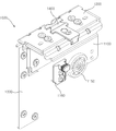
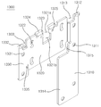
도 3은 본 발명의 바람직한 제1실시예에 따른 슬라이딩 롤러 높이 조절 장치의 정면 사시도.
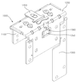
도 4는 본 발명의 바람직한 제1실시예에 따른 슬라이딩 롤러 높이 조절 장치의 배면 사시도.
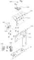
도 5는 본 발명의 바람직한 제1실시예에 따른 슬라이딩 롤러 높이 조절 장치의 정면 분해 사시도.
도 6은 본 발명의 바람직한 제1실시예에 따른 슬라이딩 롤러 높이 조절 장치의 배면 분해 사시도.
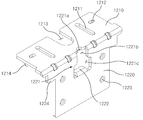
도 7은 본 발명의 바람직한 제1실시예에 따른 슬라이딩 롤러 높이 조절 장치의 높이조절 브라켓의 배면 사시도.
도 8은 본 발명의 바람직한 제1실시예에 따른 슬라이딩 롤러 높이 조절 장치의 지지 브라켓의 배면 사시도.
도 9는 본 발명의 바람직한 제1실시예에 따른 슬라이딩 롤러 높이 조절 장치의 두께조절 브라켓의 정면 사시도.
도 10은 본 발명의 바람직한 제1실시예에 따른 슬라이딩 롤러 높이 조절 장치의 높이조절부의 정면 분해 사시도.
도 11은 본 발명의 바람직한 제1실시예에 따른 슬라이딩 롤러 높이 조절 장치의 높이조절부의 배면 분해 사시도.
도 12는 본 발명의 바람직한 제1실시예에 따른 슬라이딩 롤러 높이 조절 장치의 높이를 낮췄을 때의 상태도.
도 13은 본 발명의 바람직한 제1실시예에 따른 슬라이딩 롤러 높이 조절 장치의 높이를 높혔을 때의 상태도.
도 14는 본 발명의 바람직한 제2실시예에 따른 슬라이딩 롤러 높이 조절 장치의 정면 사시도.
도 15는 본 발명의 바람직한 제2실시예에 따른 슬라이딩 롤러 높이 조절 장치의 배면 사시도.
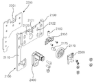
도 16은 본 발명의 바람직한 제2실시예에 따른 슬라이딩 롤러 높이 조절 장치의 정면 분해 사시도.
도 17은 본 발명의 바람직한 제2실시예에 따른 슬라이딩 롤러 높이 조절 장치의 높이조절 브라켓의 정면 사시도.
도 18은 본 발명의 바람직한 제2실시예에 따른 슬라이딩 롤러 높이 조절 장치의 지지 브라켓의 정면 사시도.
도 19는 본 발명의 바람직한 제2실시예에 따른 슬라이딩 롤러 높이 조절 장치의 높이를 낮췄을 때의 상태도.
도 20은 본 발명의 바람직한 제2실시예에 따른 슬라이딩 롤러 높이 조절 장치의 높이를 높혔을 때의 상태도.1 is a perspective view of a storage space in which a sliding roller height adjustment device according to a preferred embodiment of the present invention is installed.
2 is a side view of a storage space in which a sliding roller height adjusting device according to a preferred embodiment of the present invention is installed;
3 is a front perspective view of a sliding roller height adjusting device according to a first preferred embodiment of the present invention;
4 is a rear perspective view of a sliding roller height adjusting device according to a first preferred embodiment of the present invention;
5 is a front exploded perspective view of the sliding roller height adjusting device according to the first preferred embodiment of the present invention.
6 is a rear exploded perspective view of the sliding roller height adjusting device according to the first preferred embodiment of the present invention.
7 is a rear perspective view of the height adjustment bracket of the sliding roller height adjustment device according to the first preferred embodiment of the present invention.
8 is a rear perspective view of the support bracket of the sliding roller height adjusting device according to the first preferred embodiment of the present invention.
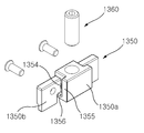
9 is a front perspective view of the thickness adjustment bracket of the sliding roller height adjustment device according to the first preferred embodiment of the present invention.
10 is a front exploded perspective view of the height adjusting unit of the sliding roller height adjusting device according to the first preferred embodiment of the present invention;
11 is a rear exploded perspective view of the height adjusting unit of the sliding roller height adjusting device according to the first preferred embodiment of the present invention;
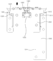
12 is a state diagram when the height of the sliding roller height adjusting device according to the first preferred embodiment of the present invention is lowered.
13 is a state diagram when the height of the sliding roller height adjustment device according to the first preferred embodiment of the present invention is increased.
14 is a front perspective view of a sliding roller height adjusting device according to a second preferred embodiment of the present invention;
15 is a rear perspective view of a sliding roller height adjusting device according to a second preferred embodiment of the present invention;
16 is a front exploded perspective view of a sliding roller height adjusting device according to a second preferred embodiment of the present invention;
17 is a front perspective view of a height adjustment bracket of a sliding roller height adjustment device according to a second preferred embodiment of the present invention;
18 is a front perspective view of a support bracket of a sliding roller height adjusting device according to a second preferred embodiment of the present invention;
19 is a state diagram when the height of the sliding roller height adjustment device according to the second preferred embodiment of the present invention is lowered.
20 is a state diagram when the height of the sliding roller height adjustment device according to the second preferred embodiment of the present invention is increased.
이하, 본 발명의 바람직한 실시예를 첨부도면을 참조하여 상세히 설명하면 다음과 같다.Hereinafter, preferred embodiments of the present invention will be described in detail with reference to the accompanying drawings.
참고적으로, 이하에서 설명될 본 발명의 구성들 중 종래기술과 동일한 구성에 대해서는 전술한 종래기술을 참고하기로 하고 별도의 상세한 설명은 생략한다.For reference, among the components of the present invention to be described below, for the same components as those of the prior art, reference will be made to the above prior art, and a separate detailed description thereof will be omitted.
여기서 사용되는 전문용어는 단지 특정 실시예를 언급하기 위한 것이며, 본 발명을 한정하는 것을 의도하지 않는다. 여기서 사용되는 단수 형태들은 문구들이 이와 명백히 반대의 의미를 나타내지 않는 한 복수 형태들도 포함한다.The terminology used herein is for the purpose of referring to specific embodiments only, and is not intended to limit the invention. As used herein, the singular forms also include the plural forms unless the phrases clearly indicate the opposite.
명세서에서 사용되는 "포함하는"의 의미는 특정 특성, 영역, 정수, 단계, 동작, 요소 및/또는 성분을 구체화하며, 다른 특정 특성, 영역, 정수, 단계, 동작, 요소, 성분 및/또는 군의 존재나 부가를 제외시키는 것은 아니다.The meaning of "comprising," as used herein, specifies a particular characteristic, region, integer, step, operation, element and/or component, and other specific characteristic, region, integer, step, operation, element, component, and/or group. It does not exclude the existence or addition of
본 발명의 바람직한 실시예에서 전후방향은 저장공간(20)의 내외방향이고, 좌우방향은 저장공간(20)의 좌우방향이고, 상하방향은 저장공간(20)의 높이방향을 의미한다.In a preferred embodiment of the present invention, the front-rear direction is the inside and outside direction of the
또한, 본 발명의 바람직한 실시예에서 도 1에 도시된 바와 같이, 저장공간(20)에는 슬라이딩 도어가 설치되며, 상기 슬라이딩 도어는 아웃도어(40)와, 아웃도어(40)보다 내측에 설치되어 열리면 아웃도어(40)의 내측에 겹쳐지게 되는 인도어(30)를 포함한다.In addition, in a preferred embodiment of the present invention, as shown in FIG. 1 , a sliding door is installed in the
=========== 제1실시예 ======================== First embodiment =============
본 발명의 바람직한 제1실시예에서는 도 2에 도시된 바와 같이, 저장공간(20)의 아웃도어(40)에 설치되는 슬라이딩 롤러 높이조절 장치에 대해 설명하기로 한다.In the first preferred embodiment of the present invention, as shown in FIG. 2 , a sliding roller height adjustment device installed in the outdoor 40 of the
도 3 내지 도 6에 도시된 바와 같이, 슬라이딩 롤러 높이조절 장치의 슬라이딩 롤러(1000)는 아웃도어(40)에 설치되는 지지 브라켓(1300)과, 지지 브라켓(1300)에 상하방향으로 이동 가능하게 설치되는 조절 브라켓을 포함한다.3 to 6 , the
슬라이딩 롤러(1000)는 아웃도어(40) 상부의 양측 모서리에 설치된다.The
본 발명의 바람직한 제1실시예에서는 아웃도어(40)에 설치되는 두 슬라이딩 롤러(1000) 중 아웃도어(40) 좌측에 설치되는 슬라이딩 롤러(1000)를 기준으로 서술하도록 한다.In the first preferred embodiment of the present invention, the
상기 조절 브라켓은 지지 브라켓(1300)에 나사결합 되는 높이조절 브라켓(1200)과, 높이조절 브라켓(1200)과 나사결합 되고 레일 프레임(50)에 설치되는 바퀴(1150)가 설치되는 두께조절 브라켓(1100)을 포함한다.The adjustment bracket includes a
높이조절 브라켓(1200)은 도 7에 보다 상세하게 도시되어 있다.The
높이조절 브라켓(1200)은 지지 브라켓(1300)에 나사결합되는 후방판(1220)과, 후방판(1220)의 상부에서 전방으로 절곡되어 형성되는 상판(1210)을 포함한다.The
상판(1210) 및 후방판(1220)은 전체적으로 사각판의 형태로 형성된다.The
후방판(1220)의 좌우방향 폭은 상판(1210)의 좌우방향 폭보다 좁게 형성된다. 이로 인해 후방판(1220)의 양측에는 하부 및 외측이 개방되고, 전후방향으로 관통되게 홈이 형성된다.The left-right width of the
상판(1210) 후방의 중앙에서 후방판(1220) 상부에 걸쳐 제1요홈(1221)이 형성된다.A first
제1요홈(1221)은 상판(1210)의 후방이 개방되고 상하방향으로 관통되게 형성되는 높이조절나사 조작홈(1221a)과, 높이조절나사 조작홈(1221a)과 연통되고 후방판(1220)이 전후방향으로 관통되게 형성되는 블록 가이드홈(1221b)과, 블록 가이드홈(1221b)과 연통되고 블록 가이드홈(1221b)의 하부에 전후방향으로 관통되게 형성되는 블록 설치홈(1221c)을 포함한다.The first
높이조절나사 조작홈(1221a)은 반원형태로 형성된다.The height adjustment screw operation groove (1221a) is formed in a semicircular shape.
블록 가이드홈(1221b)은 사각형태로 형성된다. 블록 가이드홈(1221b)의 좌우방향 폭은 후술할 블록(1350) 후방의 좌우방향 폭과 유사하거나 보다 크게 형성되어, 블록(1350)의 상하방향 슬라이딩은 블록 가이드홈(1221b)에 의해 가이드될 수 있다.The
블록 설치홈(1221c)의 좌우방향 폭은 블록 가이드홈(1221b)의 좌우방향 폭보다 넓게 형성된다.The width in the left and right direction of the
블록 설치홈(1221c)에는 블록(1350)에 전방에서 후방으로 지지 브라켓(1300)에 결합되는 나사의 단부가 삽입된다. 이로 인해 블록(1350)이 상하방향으로 슬라이딩될 때 상기 나사와 높이조절 브라켓(1200) 사이의 간섭이 방지된다.An end of a screw coupled to the
블록 설치홈(1221c)의 하단에는 지지판(1222)이 전방으로 절곡되게 형성된다.At the lower end of the
지지판(1222)은 제1요홈(1221)에 해당하는 철판의 일부를 전방으로 구부려서 형성되므로 별도의 부품이 요구되지 않는다.The
지지판(1222)은 후술할 블록(1350)의 조절나사(1360)의 밑면 전체가 올라갈 수 있도록 충분히 전방으로 연장되게 형성된다. 이러한 지지판(1222)으로 인해 조절나사(1360)는 견고하게 지지될 수 있다.The
상판(1210)의 좌측 및 우측에는 상하방향으로 관통되게 형성되는 두께조절 슬롯(1211)이 전후방향으로 길게 형성된다.On the left and right sides of the
두께조절 슬롯(1211)을 통해 후술할 두께조절 브라켓(1100)에 설치되는 나사에 의해 높이조절 브라켓(1200)은 두께조절 브라켓(1100)에 결합된다.The
좌측 및 우측의 두께조절 슬롯(1211)보다 외측에는 상하방향으로 관통되게 눈금확인홈(1212)이 형성된다.A
눈금확인홈(1212)은 좌우방향으로 길게 형성된다.The
눈금확인홈(1212)은 후술할 두께조절 브라켓(1100)의 눈금(1124)의 상부에 위치하게 배치된다. 이로 인해 사용자는 눈금확인홈(1212)을 통해 슬라이딩 롤러(1000)의 두께를 손쉽게 확인할 수 있다.The
눈금확인홈(1212)의 좌측 및 우측의 형태를 반원 형태 또는 꺽쇠 형태로 형성하여 사용자가 눈금확인홈(1212)의 중심을 쉽게 인지하게 할 수 있다.By forming the left and right sides of the
눈금확인홈(1212)이 좌측 및 우측에 형성됨으로써, 사용자는 두 눈금확인홈(1212)의 눈금을 확인하고 손쉽게 좌우 균형을 맞출 수 있다.Since the
상판(1210)의 중앙에는 전방으로 개방되고 상하방향으로 관통되게 이탈방지부 가이드홈(1213)이 형성된다.In the center of the
이탈방지부 가이드홈(1213)은 두께조절 슬롯(1211)의 사이 배치된다.The separation prevention
이탈방지부 가이드홈(1213)은 후방이 호의 형상으로 형성된다. The separation prevention
상판(1210)의 좌측 및 우측에는 전방 및 외측이 개방되고 상하방향으로 관통되도록 두께조절 브라켓 삽입홈(1214)이 형성된다. 즉, 두께조절 브라켓 삽입홈(1214)은 내측 및 후방에 막히게 형성된다.A thickness adjustment
두께조절 브라켓 삽입홈(1214)에는 후술할 두께조절 브라켓(1100)의 가이드돌기(1125)가 삽입된다. A
두께조절 브라켓 삽입홈(1214)에 의해 가이드돌기(1125)의 전후방향 슬라이딩이 가이드 되고, 가이드돌기(1125)가 후방으로 이탈되지 않는다.The front and rear sliding of the
높이조절 브라켓(1200)의 후방판(1220)의 상부 및 하부의 양측에 전후방향으로 관통되게 높이조절나사 결합홈(1223)이 형성된다.A height adjustment
높이조절나사 결합홈(1223)은 원형으로 형성된다.The height adjustment
상부에 형성되는 높이조절나사 결합홈(1223)은 블록 설치홈(1221c)의 외측에 형성된다.The height adjustment
나사는 후술할 지지 브라켓(1300)의 높이조절 슬롯(1322)을 통해 높이조절 브라켓(1200)의 높이조절나사 결합홈(1223)에 끼워진다.The screw is inserted into the height adjustment
후방판(1220)의 양측 상부에는 좌측 또는 우측으로 돌출되게 지지 브라켓 걸림부(1224)가 형성된다.Support
지지 브라켓 걸림부(1224)는 사각판의 형상으로 형성된다.The support
지지 브라켓 걸림부(1224)는 후술할 지지 브라켓(1300)의 제1,2높이조절 브라켓 삽입홈(1313,1333)에 삽입된다. 즉, 지지 브라켓 걸림부(1224)의 하부는 제1,2높이조절 브라켓 삽입홈(1313,1333)에 의해 가로막혀, 높이조절 브라켓(1200)의 상하방향 슬라이딩이 제한될 수 있다.The support
지지 브라켓(1300)은 도 8에 자세하게 도시되어 있다.The
지지 브라켓(1300)은 전체적으로 판의 형태로 형성된다.The
지지 브라켓(1300)은 중앙판(1320)과, 중앙판(1320)의 좌측 후방으로 연장된 후 좌측으로 절곡되게 형성되는 좌측판(1310)과, 중앙판(1320)의 우측 후방으로 연장된 후 우측으로 절곡되게 형성되는 우측판(1330)을 포함한다.The
즉, 중앙판(1320)의 후방에는 양 옆이 좌측판(1310)과 우측판(1330)으로 가로막힌 공간이 형성된다. 상기 공간에는 높이조절 브라켓(1200)의 후방판(1220)이 삽입되어, 지지 브라켓(1300)과 조립된다.That is, at the rear of the
중앙판(1320)은 사각판의 형태로 형성된다.The
중앙판(1320)의 중앙에는 상부가 개방되고, 전후방향으로 관통되게 제2요홈(1321)이 형성된다. In the center of the
제2요홈(1321)은 제2요홈(1321)의 후방에 배치되는 높이조절 브라켓(1200)의 제1요홈(1221)과 연통된다.The second
제2요홈(1321)은 상부가 개방되게 형성되는 블록 걸림홈(1321a)과, 블록 걸림홈(1321a)과 연통되며 블록 걸림홈(1321a)의 하부에 형성되는 블록 설치홈(1321b)을 포함한다.The second
블록 설치홈(1321b)의 좌우방향 폭은 높이조절 브라켓(1200)의 지지판(1222)의 좌우방향 폭보다 넓게 형성된다.The left-right width of the
이로 인해 블록 설치홈(1321b)에는 높이조절 브라켓(1200)의 지지판(1222)이 삽입된다.For this reason, the
또한 블록 설치홈(1321b)의 좌우방향 폭은 높이조절 브라켓(1200)의 블록 설치홈(1221c)의 좌우방향 폭보다 좁게 형성된다.In addition, the width in the left and right direction of the
블록 걸림홈(1321a)의 좌측 및 우측에는 블록 걸림홈(1321a)의 내측으로 돌출되게 제1블록 걸림판(1323)이 형성된다.A first
즉, 블록 걸림홈(1321a)의 좌우방향 폭은 블록 설치홈(1321b)의 좌우방향 폭보다 좁게 형성된다.That is, the width in the left and right direction of the
이로 인해 후술할 블록(1350)의 하부는 블록 설치홈(1321b)에 설치된 후, 블록 걸림홈(1321a)에 걸려 고정된다.For this reason, the lower part of the
좌측 및 우측의 제1블록 걸림판(1323)에는 전후방향으로 관통되게 블록 결합홈(1325)이 형성된다.
블록 결합홈(1325)은 조립 후 높이조절 브라켓(1200)의 블록 설치홈(1221c)에 연통되도록 배치된다.The
블록 결합홈(1325)에는 후술할 블록(1350)이 나사결합 된다.A
이로 인해 높이조절 브라켓(1200)이 지지 브라켓(1300)에 대해 상하방향으로 슬라이딩 되더라도 블록 결합홈(1325)에 설치된 나사가 높이조절 브라켓(1200)과 간섭되지 않는다.Due to this, even if the
중앙판(1320)의 상부 및 하부의 양측에는 전후방향으로 관통되게 높이조절 슬롯(1322)이 형성된다.A
높이조절 슬롯(1322)은 상하방향으로 길게 형성된다.The
높이조절 슬롯(1322)은 높이조절 브라켓(1200)의 높이조절나사 결합홈(1223)과 연통된다.The
이로 인해 높이조절 슬롯(1322)을 통해 높이조절나사 결합홈(1223)에 결합되는 나사는, 높이조절 슬롯(1322)에 의해 가이드 되며 상하방향으로 슬라이딩 된다.For this reason, the screw coupled to the height adjustment
제1블록 걸림판(1323)의 상부에는 전방으로 절곡되도록 제2블록 걸림판(1324)이 형성된다.A second
좌측 및 우측의 제2블록 걸림판(1324)의 바로 외측에는 상부가 개방되도록 요홈이 형성되어, 제1,2블록 걸림판(1323,1324)은 좌우방향으로 탄성변형될 수 있다. 이로 인해 블록(1350)을 조작할 때 제1,2블록 걸림판(1323,1324)에 가해지는 외력에 의한 영향을 최소화할 수 있다.A recess is formed on the right outside of the left and right second
좌측판(1310)은 중앙판(1320)보다 아래쪽으로 돌출되게 형성된다.The
좌측판(1310)은 제1사각판의 우측 하부에 상기 제1사각판의 상하방향 길이보다 상하방향 길이가 좁은 제2사각판이 연결되어 있는 형상으로 형성된다. 상기 제1사각판의 밑면과 상기 제2사각판의 밑면은 동일 선상에 위치한다.The
상기 제1사각판의 상하방향 길이는 중앙판(1320)의 상하방향 길이의 2배 이상이 되도록 형성되는 것이 바람직하다.The vertical length of the first rectangular plate is preferably formed to be at least twice the vertical length of the
상기 제2사각판을 걸림판(1314)이라고 한다.The second square plate is called a
걸림판(1314)은 중앙판(1320)의 좌측 하부에 배치된다. 즉, 중앙판(1320)의 좌측 하부는 걸림판(1314)에 상부에 걸려 아랫방향으로의 슬라이딩이 제한된다.The
중앙판(1320)과 좌측판(1310)의 일부는 제1이격홈(1315)에 의해 이격된다.A portion of the
제1이격홈(1315)은 중앙판(1320)의 좌측하면과 걸림판(1314)의 상면 사이에 형성되는 제1구간과, 상기 제1구간과 연통되고 중앙판(1320) 하부의 좌측면과 상기 제1사각판 사이에 형성되는 제2구간과, 상기 제2구간과 연통되고 상기 제1사각판에 노치 형태로 형성되는 제3구간을 포함한다.The
좌측판(1310) 좌측 및 걸림판(1314)의 우측에는 전후방향으로 관통되게 제1아웃도어 결합홈(1311)이 형성된다.A first
제1아웃도어 결합홈(1311)은 복수개로 형성된다.The first
제1아웃도어 결합홈(1311)은 상기 제1사각판의 상부, 중앙부, 하부 및 걸림판(1314)의 하부에 각각 형성된다.The first
제1아웃도어 결합홈(1311)을 통해 좌측판(1310)은 아웃도어(40)에 나사결합된다.The
제1이격홈(1315)과 제1아웃도어 결합홈(1311)에 의해 좌측판(1310)은 아웃도어(40)에 밀착되게 결합될 수 있다. 또한, 아웃도어(40) 모서리가 휘는 현상을 효과적으로 방지할 수 있다.The
좌측판(1310)의 좌측 상부에는 후방으로 절곡되게 제1걸침판(1312)이 형성된다.A
제1걸침판(1312)의 밑면은 아웃도어(40)의 상면에 걸쳐진다. The bottom surface of the
제1걸침판(1312)의 우측에는 상부가 개방되고 전후방향으로 관통되게 제1높이조절 브라켓 삽입홈(1313)이 형성된다.A first height adjustment
제1높이조절 브라켓 삽입홈(1313)에는 제1높이조절 높이조절 브라켓(1200)의 지지 브라켓 걸림부(1224)가 삽입된다. 이로 인해 높이조절 브라켓(1200)의 상하방향 슬라이딩이 제1높이조절 브라켓 삽입홈(1313)에 의해 가로막힌다.The support
우측판(1330)은 전체적으로 사각판의 형태로 형성된다.The
우측판(1330)은 중앙판(1320)보다 아래쪽으로 약간 돌출되게 형성된다.The
중앙판(1320)과 우측판(1330)의 일부는 제2이격홈(1335)에 의해 이격된다.A portion of the
제2이격홈(1335)은 중앙판(1320) 하부의 우측면과 우측판(1330)의 좌측면 사이에 형성되는 제1구간과, 상기 제1구간과 연통되고 우측판(1330)에 노치 형태로 형성되는 제2구간을 포함한다.The
우측판(1330)의 상부 및 하부에는 전후방향으로 관통되게 제2아웃도어 결합홈(1331)이 형성된다. A second
제2아웃도어 결합홈(1331)을 통해 지지 브라켓(1300)은 아웃도어(40)에 나사결합된다.The
제2이격홈(1335)과 제2아웃도어 결합홈(1331)에 의해 우측판(1330)은 아웃도어(40)에 밀착되게 결합될 수 있다. 또한, 아웃도어(40) 모서리가 휘는 현상을 효과적으로 방지할 수 있다.The
우측판(1330)의 우측 상부에는 후방으로 절곡되게 제2걸침판(1332)이 형성된다.A
제2걸침판(1332)의 밑면은 아웃도어(40)의 상면에 걸쳐진다.The lower surface of the
이러한 제1,2걸침판(1312,1332)에 의해 지지 브라켓(1300)을 아웃도어(40)에 결합할 때 지지 브라켓(1300)의 좌우 균형을 원활하게 맞추고, 지지 브라켓(1300)의 상하방향으로의 위치를 원활하게 설정할 수 있다.When the
두께조절 브라켓(1100)은 도 9에 상세하게 도시되어 있다.The
두께조절 브라켓(1100)은 높이조절 브라켓(1200)에 나사결합되는 상판(1120)과, 바퀴(1150)가 설치되는 전방판(1110)을 포함한다. The
전방판(1110) 및 상판(1120)은 전체적으로 사각판의 형태로 형성된다.The
상판(1120)은 높이조절 브라켓(1200)의 상판(1210)의 하부에 설치된다.The
상판(1120) 후방의 중앙에서 전방판(1110) 상부 일부에 걸쳐 이탈방지부 관통홈(1123)이 형성된다.A separation prevention part through-
이탈방지부 관통홈(1123)은 전방이 개방되고 상하방향으로 관통되게 형성된다.The separation prevention part through-
이탈방지부 관통홈(1123)에는 이탈방지부(1400)의 전방이 삽입되어 전후방향으로 슬라이딩 된다.The front of the
상판(1120)의 중앙에는 설치나사 결합홈(1121)이 상하방향으로 관통되게 형성된다.In the center of the
설치나사 결합홈(1121)은 이탈방지부 관통홈(1123)보다 후방에 형성된다.The installation
이탈방지부(1400)는 위에서 아래로 설치나사 결합홈(1121)에 설치되는 이탈방지나사(1405)에 의해 두께조절 브라켓(1100)에 설치된다.The
상판(1120)의 좌측 및 우측에는 두께조절나사 결합홈(1122)이 상하방향으로 관통되게 형성된다.On the left and right sides of the
두께조절나사 결합홈(1122)은 상판(1120)의 좌측 및 우측에 각각 복수개로 형성된다.A plurality of thickness adjusting
두께조절나사 결합홈(1122)은 높이조절 브라켓(1200)의 두께조절 슬롯(1211)과 연통되도록 배치된다.The thickness adjustment
두께조절 슬롯(1211)을 통과한 뒤 두께조절나사 결합홈(1122)에 결합되는 나사에 의해 두께조절 브라켓(1100)과 높이조절 브라켓(1200)은 서로 결합되고, 상기 나사는 두께조절 슬롯(1211)에 대해 전후방향으로 슬라이딩 된다.After passing through the
상판(1120)의 좌측 및 우측에는 눈금(1124)이 형성된다.A
눈금(1124)은 높이조절 브라켓(1200)의 눈금확인홈(1212)을 통해 확인 가능하도록 상판(1120)의 상면에 배치된다.The
눈금(1124)은 두께조절나사 결합홈(1122)보다 외측에 배치된다.The
눈금(1124)에는 전후방향으로 이격되게 형성되는 눈금선과, 상기 눈금선 2개마다 한번씩 형성되는 숫자를 포함한다.The
상기 눈금선의 좌우방향 길이는 눈금확인홈(1212)의 좌우방향길이보다 길게 형성되어, 사용자는 눈금확인홈(1212)을 통해 상기 눈금선을 확인할 때 쉽게 상기 눈금선이 상기 눈금확인홈(1212)의 중앙에 오는지 확인할 수 있다.The left and right length of the scale line is longer than the left and right length of the
상판(1120)의 좌측면 및 우측면에는 상부로 돌출되게 가이드돌기(1125)가 형성된다.A
가이드돌기(1125)는 상판(1120)의 좌측면 및 우측면의 일부에만 형성이 된다.The
가이드돌기(1125)는 높이조절 브라켓(1200)의 두께조절 브라켓 삽입홈(1214)에 삽입되도록 형성된다.The
가이드돌기(1125)는 높이조절 브라켓(1200)에 대한 두께조절 브라켓(1100)의 전후방향 슬라이딩을 좌우방향으로 가이드한다.The
전방판(1110)의 중앙에는 전후방향으로 관통되게 바퀴축 결합홈(1111)이 형성된다.A wheel
바퀴축 결합홈(1111)에는 바퀴축(1155)이 결합되고, 바퀴축(1155)에는 바퀴(1150)가 결합된다. 바퀴(1150)에는 바퀴축(1155)과 결합되는 홈이 전후방향으로 관통되게 형성된다.A
전방판(1110)의 좌측 및 우측에는 전후방향으로 관통되게 댐퍼 결합부(1112)가 형성된다.A
댐퍼 결합부(1112)는 전방판(1110)의 좌측 및 우측에 각각 위아래로 2개씩 형성된다.The
댐퍼 결합부(1112)에는 댐퍼(1160)가 나사결합된다.A
댐퍼(1160)는 아웃도어(40)에서 슬라이딩 롤러(1000)가 설치되는 방향에 따라 전방판(1110)의 좌측 또는 우측에 설치된다.The
본 발명의 바람직한 제1실시예의 경우, 슬라이딩 롤러(1000)가 아웃도어(40)에 좌측에 설치되므로, 댐퍼(1160) 또한 전방판(1110)의 좌측에 설치된다.In the case of the first preferred embodiment of the present invention, since the sliding
댐퍼(1160)는 일측이 전방으로 돌출되게 형성된다. 상기 일측에는 고무로 된 오링이 설치된다. 댐퍼(1160)는 레일 프레임(50)과 별개로 형성되는 댐퍼 레일에 설치되어 상기 댐퍼 레일을 따라 슬라이딩 되는 집게에 결합되거나 결합 해제되어 아웃도어(40)가 부드럽게 닫히거나 열리게 하는 역할을 한다.The
지지 브라켓(1300)에 설치되는 블록(1350)은 도 10 내지 도 11에 상세하게 도시되어 있다.The
블록(1350)은 직육면체 형상의 나사체결부(1350a)와, 나사체결부(1350a)의 전방에 좌우방향으로 긴 사각판 형상으로 형성되는 브라켓결합부(1350b)를 포함한다.The
나사체결부(1350a)에는 상하방향으로 관통되게 조절나사 체결홈(1351)이 형성된다.An adjustment
조절나사 체결홈(1351) 내측에는 암나사선이 형성된다.A female thread is formed inside the adjusting
이로 인해 표면에 수나사선이 형성되는 조절나사(1360)가 조절나사 체결홈(1351)에 나사결합된다.Due to this, the adjusting
조절나사(1360)의 상부에는 육각렌치를 끼울 수 있는 렌치홈(1361)을 형성하여 육각렌치를 이용하여 조절나사(1360)를 회전시킬 수 있다.A
나사체결부(1350a)의 후방에는 좌측 및 우측으로 돌출되게 블록 가이드부(1355)가 형성된다.A
블록 가이드부(1355)의 좌우방향 길이는 높이조절 브라켓(1200)의 블록 가이드홈(1221b)의 좌우방향 폭과 유사하거나 보다 작게 형성된다.The length in the left and right direction of the
블록 가이드부(1355)로 인해 블록(1350)의 상하방향 슬라이딩은 높이조절 브라켓(1200)의 블록 가이드홈(1221b)에 의해 가이드 될 수 있다.The vertical sliding of the
블록(1350)의 후방에 형성되는 블록 가이드부(1355)의 전면과 블록(1350)의 전방에 형성되는 브라켓결합부(1350b)의 후면은 서로 이격 되어, 사이에 공간이 형성되는데 상기 공간을 브라켓 끼움홈(1354)이라 한다.The front surface of the
브라켓 끼움홈(1354)의 하부에는 브라켓 걸림부(1356)가 좌측 또는 우측으로 돌출되게 형성된다.In the lower portion of the bracket
브라켓 걸림부(1356)의 측면과 블록 가이드부(1355)의 측면은 같은 선상에 위치한다.The side surface of the
이로 인해 브라켓 끼움홈(1354)에는 지지 브라켓(1300)의 제1블록 걸림판(1323)이 끼워진다. For this reason, the first
또한, 브라켓 걸림부(1356)의 상면에 제1블록 걸림판(1323)이 하면이 걸린다. 이로 인해 블록(1350)이 윗방향으로 힘을 받을 때 상기 힘이 나사 삽입홈(1352)에 설치된 나사와 제1블록 걸림판(1323)에 분산되어 안정성이 높아진다.In addition, the lower surface of the first
브라켓결합부(1350b)의 상면은 나사체결부(1350a)의 상면보다 아래쪽에 형성된다.The upper surface of the
브라켓결합부(1350b)의 좌측 및 우측에는 전후방향으로 관통되게 나사 삽입홈(1352)이 형성된다.
이로 인해 브라켓결합부(1350b)는 나사 삽입홈(1352)에 전방에서 후방으로 삽입되는 나사에 의해 지지 브라켓(1300)에 결합된다.For this reason, the
또한, 브라켓결합부(1350b)의 상면은 지지 브라켓(1300)의 제2블록 걸림판(1324)에 접하게 된다.In addition, the upper surface of the bracket coupling portion (1350b) is in contact with the second
브라켓결합부(1350b)의 좌측 및 우측에는 블록 지지부(1353)가 하부로 돌출되게 형성된다.On the left and right sides of the
블록 지지부(1353)의 후면은 브라켓결합부(1350b)의 후면과 같은 선상에 배치된다.The rear surface of the
블록 지지부(1353)로 인해 조절나사(1360)를 회전시킬 때 블록(1350)에 전달되는 비틀림 응력이 분산될 수 있다.Torsional stress transmitted to the
이하에서는 도 12 내지 도 13을 참고하여, 슬라이딩 롤러(1000)의 높이를 조절하는 방법에 대해 서술하기로 한다.Hereinafter, a method of adjusting the height of the sliding
도 12에 도시된 바와 같이, 조절나사(1360)가 블록(1350)에 대해 아랫방향으로 이동하도록 조절나사(1360)를 돌리면, 조절나사(1360)가 높이조절 브라켓(1200)의 지지판(1222)을 아랫방향으로 밀어낸다. 이로 인해 결과적으로 높이조절 브라켓(1200)이 내려오게 된다.12, when the adjusting
높이조절 브라켓(1200)의 지지 브라켓 걸림부(1224)가 지지 브라켓(1300)에 닿거나, 지지 브라켓(1300)의 제1,2걸침판(1312,1332) 또는 걸림판(1314)이 높이조절 브라켓(1200)에 닿거나, 도 12에는 도시되지 않았지만 지지 브라켓(1300)의 높이조절 슬롯(1322)에 설치된 나사가 높이조절 슬롯(1322)의 단부까지 슬라이딩 될 때까지 조절나사(1360)를 돌리면, 높이조절 브라켓(1200)은 지지 브라켓(1300)에 대해 상측으로 슬라이딩 되지 않게 고정된다.The support
이 상태에서 도 13에 도시된 바와 같이, 조절나사(1360)가 블록(1350)에 대해 윗방향으로 이동하도록 조절나사(1360)를 돌리면, 조절나사(1360)와 지지판(1222) 사이에 틈이 형성되어 높이조절 브라켓(1200)이 상기 틈만큼 상부로 들릴 수 있게 된다.In this state, as shown in FIG. 13, when the adjusting
조절나사(1360)가 블록(1350)의 하부로 돌출되지 않을때까지 조절나사(1360)를 돌리면, 블록(1350)의 하면과 지지판(1222)의 상면 사이에 공간이 형성된다. 상기 공간에 의해 높이조절 브라켓(1200)은 지지 브라켓(1300)에 대해 상측방향으로 슬라이딩 될 수 있다.When the adjusting
높이조절 브라켓(1200)은 높이조절 브라켓(1200)과 결합된 두께조절 브라켓(1100)에 설치된 바퀴(1150)가 레일 프레임(50)에 걸쳐지므로, 이로 인해 위쪽으로 힘을 받는다. 즉, 바퀴(1150)가 레일 프레임(50)에 걸쳐지면 높이조절 브라켓(1200)은 상기 공간만큼 위치가 높아진다.The
상술한 원리를 이용하여, 조절나사(1360)를 돌림으로써 사용자는 높이조절 브라켓(1200)의 높이를 조절할 수 있다.Using the above-described principle, by turning the adjusting
=========== 제2실시예 ======================== Second embodiment =============
본 발명의 바람직한 제2실시예에서는 도 2에 도시된 바와 같이, 저장공간(20)의 인도어(30)에 설치되는 슬라이딩 롤러 높이조절 장치에 대해 설명하기로 한다.In the second preferred embodiment of the present invention, as shown in FIG. 2 , a sliding roller height adjustment device installed in the
도 14 내지 도 16에 도시된 바와 같이, 슬라이딩 롤러 높이조절 장치의 슬라이딩 롤러(2000)는 인도어(30)에 설치되는 지지 브라켓(2100)과, 지지 브라켓(2100)에 상하방향으로 이동 가능하게 설치되는 높이조절 브라켓(2200)을 포함한다.14 to 16 , the sliding
슬라이딩 롤러(2000)는 인도어(30) 상부의 양측 모서리에 설치된다.The sliding
본 발명의 바람직한 제3실시예에서는 인도어(30)에 설치되는 두 슬라이딩 롤러(2000) 중 인도어(30) 좌측에 설치되는 슬라이딩 롤러(2000)를 기준으로 서술하도록 한다.In the third preferred embodiment of the present invention, the sliding
높이조절 브라켓(2200)은 도 17에 상세하게 도시되어 있다.The
높이조절 브라켓(2200)은 전체적으로 판의 형태로 형성된다.The
높이조절 브라켓(2200)은 제1사각판과, 상기 제1사각판의 좌측 하부로 돌출되게 형성되는 제2사각판을 포함한다. 즉, 높이조절 브라켓(2200)은 'L'자 형태로 형성된다.The
높이조절 브라켓(2200)의 중앙에는 상부가 개방되게 제1요홈(2201)이 형성된다.A first
제1요홈(2201)의 하단에는 지지판(2202)이 전방으로 절곡되게 형성된다.A
지지판(2202)은 제1요홈(2201)에 해당하는 철판의 일부를 전방으로 구부려서 형성되므로 별도의 부품이 요구되지 않는다.Since the
지지판(2202)은 후술할 블록(2150)의 조절나사(2160)의 밑면 전체가 올라갈 수 있도록 충분히 전방으로 연장되게 형성된다. 이러한 지지판(2202)으로 인해 조절나사(2160)는 견고하게 지지될 수 있다.The
제1요홈(2201)의 아래에는 전후방향으로 관통되게 바퀴축 결합홈(2203)이 형성된다. 바퀴축 결합홈(2203)에는 전방에서 후방으로 바퀴축(2175)이 설치된다.A wheel
높이조절 브라켓(2200)의 제1사각판의 좌우측의 상부 및 하부에는 전후방향으로 관통되게 높이조절나사 결합홈(2204)이 형성된다.A height adjustment
높이조절나사 결합홈(2204)에 의해 높이조절 브라켓(2200)은 인도어(30)에 나사결합된다.The
높이조절 브라켓(2200)의 제2사각판에는 전후방향으로 관통되게 댐퍼 결합부(2208)가 형성된다.A
댐퍼 결합부(2208)는 상하방향으로 복수 개로 형성된다.A plurality of
댐퍼 결합부(2208)에는 댐퍼(2400)가 나사결합된다.A
댐퍼(2400)는 일측이 전방으로 돌출되게 형성된다. 상기 일측에는 고무로 된 오링이 설치된다. 댐퍼(2400)는 레일 프레임(50)과 별개로 형성되는 댐퍼 레일에 설치되어 상기 댐퍼 레일을 따라 슬라이딩 되는 집게에 결합되거나 결합 해제되어 인도어(30)가 부드럽게 닫히거나 열리게 하는 역할을 한다.The
높이조절 브라켓(2200)의 좌측 상부에는 범퍼나사 간섭방지홈(2205)이 형성된다.A bumper screw
범퍼나사 간섭방지홈(2205)은 상부가 개방되고 전후방향으로 관통되게 형성된다.The bumper screw
범퍼나사 간섭방지홈(2205)은 후술할 범퍼(2300)가 지지 브라켓(2100)에 나사결합된 후 높이조절 브라켓(2200)방향으로 돌출된 나사의 단부가 상하방향으로 슬라이딩 되는 높이조절 브라켓(2200)의 위치에 관계없이 서로 간섭되지 않게 해주는 역할을 한다.The bumper screw
높이조절 브라켓(2200)의 제2사각판에는 좌측으로 돌출되게 가이드부(2206)가 형성된다.A
가이드부(2206)의 상면은 우측에서 좌측으로 갈수록 아래쪽으로 경사지게 형성된다.The upper surface of the
가이드부(2206)는 후술할 지지 브라켓(2100)의 높이조절 브라켓 가이드홈(2113)에 삽입되어, 높이조절 브라켓(2200)의 제2사각판의 상하방향 슬라이딩을 가이드해줌과 동시에 상측으로의 이동을 제한한다.The
높이조절 브라켓(2200)의 제2사각판에는 하부로 돌출되게 걸림판(2207)이 형성된다.A
걸림판(2207)은 후술할 지지 브라켓(2100)의 높이조절 브라켓 삽입홈(2114a)에 삽입되어, 높이조절 브라켓(2200)의 제2사각판의 하측으로의 이동을 제한한다.The
지지 브라켓(2100)은 도 18에 자세하게 도시되어 있다.The
지지 브라켓(2100)은 전체적으로 판의 형태로 형성된다.The
지지 브라켓(2100)은 중앙판(2120)과, 중앙판(2120)의 좌측 후방으로 연장된 후 좌측으로 절곡되게 형성되는 좌측판(2110)과, 중앙판(2120)의 우측 후방으로 연장된 후 우측으로 절곡되게 형성되는 우측판(2130)을 포함한다.The
즉, 중앙판(2120)의 후방에는 양 옆이 좌측판(2110)과 우측판(2130)으로 가로막힌 공간이 형성된다. 상기 공간에는 높이조절 브라켓(2200)이 삽입되어, 지지 브라켓(2100)과 조립된다.That is, at the rear of the
중앙판(2120)은 사각판의 형태로 형성된다.The
중앙판(2120)의 중앙에는 상부가 개방되고, 전후방향으로 관통되게 제2요홈(2121)이 형성된다.In the center of the
제2요홈(2121)은 제2요홈(2121)의 후방에 배치되는 높이조절 브라켓(2200)의 제1요홈(2201)과 연통된다.The
제2요홈(2121)은 상부가 개방되게 형성되는 블록 걸림홈(2121a)과, 블록 걸림홈(2121a)과 연통되며 블록 걸림홈(2121a)의 하부에 형성되는 블록 설치홈(2121b)을 포함한다.The second
블록 설치홈(2121b)의 좌우방향 폭은 높이조절 브라켓(2200)의 지지판(2202)의 좌우방향 폭보다 넓게 형성된다.The left-right width of the
이로 인해 블록 설치홈(2121b)에는 높이조절 브라켓(2200)의 지지판(2202)이 삽입된다.Accordingly, the
또한 블록 설치홈(2121b)의 좌우방향 폭은 높이조절 브라켓(2200)의 제1요홈(2201)의 좌우방향 폭보다 좁게 형성된다.In addition, the left-right width of the block installation groove (2121b) is formed narrower than the left-right width of the first
블록 걸림홈(2121a)의 좌우방향 폭은 블록 설치홈(2121b)의 좌우방향 폭보다 좁게 형성된다.The width in the left and right direction of the block engaging groove (2121a) is formed to be narrower than the width in the left and right direction of the block installation groove (2121b).
이로 인해 후술할 블록(2150)의 하부는 블록 설치홈(2121b)에 설치된 후, 블록 걸림홈(2121a)에 걸려 고정된다.For this reason, the lower part of the
블록 걸림홈(2121a)보다 좌측 및 우측에는 전후방향으로 관통되게 블록 결합홈(2125)이 형성된다.
블록 결합홈(2125)은 조립 후 높이조절 브라켓(2200)의 제1요홈(2201)에 연통되도록 배치된다.The
블록 결합홈(2125)에는 후술할 블록(2150)이 나사결합 된다.A
이로 인해 높이조절 브라켓(2200)이 지지 브라켓(2100)에 대해 상하방향으로 슬라이딩 되더라도 블록 결합홈(2125)에 설치된 나사가 높이조절 브라켓(2200)과 간섭되지 않는다.Due to this, even if the
중앙판(2120)의 좌우측의 상부 및 하부에는 전후방향으로 관통되게 높이조절 슬롯(2122)이 형성된다.A
높이조절 슬롯(2122)은 상하방향으로 길게 형성된다.The
높이조절 슬롯(2122)은 높이조절 브라켓(2200)의 높이조절나사 결합홈(2204)과 연통된다.The
이로 인해 높이조절 슬롯(2122)을 통해 높이조절나사 결합홈(2204)에 결합되는 나사는, 높이조절 슬롯(2122)에 의해 가이드 되며 상하방향으로 슬라이딩 된다.Due to this, the screw coupled to the height adjustment
중앙판(2120) 중앙부의 상부에는 전방으로 절곡되도록 블록 걸림판(2124)이 형성된다.A
블록 걸림판(2124)은 블록 걸림홈(2121a)의 양측에 형성된다.Block engaging
좌측 및 우측의 블록 걸림판(2124)의 바로 외측에는 상부가 개방되도록 요홈이 형성되어, 블록 걸림판(2124)은 좌우방향으로 탄성변형될 수 있다. 이로 인해 블록(2150)을 조작할 때 블록 걸림판(2124)에 가해지는 외력에 의한 영향을 최소화할 수 있다.A recess is formed in the right and outer sides of the
중앙판(2120)의 중앙에는 전후방향으로 관통되게 바퀴축 관통홈(2123)이 형성된다.A wheel shaft through-
바퀴축 관통홈(2123)에는 바퀴(2170) 및 높이조절 브라켓(2200)의 바퀴축 결합홈(2203)에 결합된 바퀴축(2175)이 통과된다.The
바퀴축 관통홈(2123)의 지름은 높이조절 슬롯(2122)의 상하방향 폭보다 크게 형성되어, 지지 브라켓(2100)에 대해 높이조절 브라켓(2200)이 상하방향으로 슬라이딩될 때 바퀴축(2175)과 지지 브라켓(2100)이 간섭되는 것을 방지해준다.The diameter of the wheel shaft through-
중앙판(2120)의 좌측 상부에는 전후방향으로 관통되게 범퍼 결합홈(2126)이 형성된다.A
범퍼 결합홈(2126)에는 범퍼(2300)가 나사결합된다.The
범퍼(2300)는 중앙판(2120)의 상부로 돌출되게 설치된다.The
범퍼(2300) 중 중앙판(2120)의 상부로 돌출된 부분에는 고무 등의 재질로 형성되는 탄성부가 위치하여, 인도어(30)를 열 때 인도어(30)의 슬라이딩 롤러(2000)와 아웃도어(40)의 슬라이딩 롤러(1000)가 서로 부딪힐 때 충격을 감소시켜주는 역할을 한다.An elastic part formed of a material such as rubber is located in a portion of the
좌측판(2110)은 중앙판(2120)보다 아래쪽으로 돌출되게 형성된다.The
좌측판(2110)은 제1사각판의 우측 하부에 제2사각판이 연결되어 있는 형상으로 형성된다. 상기 제1사각판의 밑면과 상기 제2사각판의 밑면은 동일 선상에 위치한다.The
좌측판(2110)의 제1사각판의 상하방향 길이는 중앙판(1320)의 상하방향 길이의 2배 이상이 되도록 형성되는 것이 바람직하다.The vertical length of the first rectangular plate of the
중앙판(2120)과 좌측판(2110)의 일부는 제1이격홈(2115)에 의해 이격된다.A portion of the
제1이격홈(2115)은 중앙판(2120)의 좌측 하면과 좌측판(2110)의 우측면 사이에 형성되는 제1구간과, 상기 제1구간과 연통되고 좌측판(2110)에 노치 형태로 형성되는 제2구간을 포함한다.The
좌측판(2110)의 상부, 중앙부 및 하부에는 전후방향으로 관통되게 제1인도어 결합홈(2111)이 형성된다.A first
제1인도어 결합홈(2111)을 통해 좌측판(2110)은 인도어(30)에 나사결합 된다.The
제1이격홈(2115)과 제1인도어 결합홈(2111)에 의해 좌측판(2110)은 인도어(30)에 밀착되게 결합될 수 있다. 또한, 인도어(30)의 모서리가 휘는 현상을 효과적으로 방지할 수 있다.The
좌측판(2110)의 좌측 상부에는 후방으로 절곡되게 제1걸침판(2112)이 형성된다.A
제1걸침판(2112)의 밑면은 인도어(30)의 상면에 걸쳐진다.The bottom surface of the
좌측판(2110)의 제1사각판의 우측에는 우측이 개방되고 전후방향이 관통되게 높이조절 브라켓 가이드홈(2113)이 형성된다.On the right side of the first square plate of the
높이조절 브라켓 가이드홈(2113)의 상면은 우측에서 좌측으로 갈수록 하측으로 기울어지게 형성된다.The upper surface of the height adjustment
이로 인해 높이조절 브라켓 가이드홈(2113)에 삽입되는 높이조절 브라켓(2200)의 가이드부(2206)가 위쪽으로 슬라이딩 되어 높이조절 브라켓 가이드홈(2113)의 상면에 닿을 때 힘이 분산되는 효과가 있다.Due to this, the
또한, 높이조절 브라켓 가이드홈(2113)에 의해 가이드부(2206)의 상하방향 슬라이딩이 가이드 된다.In addition, the vertical sliding of the
좌측판(2110)의 제2사각판의 상부에는 전방으로 돌출되도록 높이조절 브라켓 삽입부(2114)가 형성된다.A height adjustment
높이조절 브라켓 삽입부(2114)에는 후방 및 상부가 개방되도록 높이조절 브라켓 삽입홈(2114a)이 형성된다. 높이조절 브라켓 삽입홈(2114a)은 도 20에 도시되어 있다.A height adjustment
높이조절 브라켓 삽입홈(2114a)은 지지 브라켓(2100)의 후방에 설치되는 높이조절 브라켓(2200)의 걸림판(2207)이 삽입될 수 있도록 형성된다.The height adjustment
이러한 높이조절 브라켓 삽입홈(2114a)에 의해 높이조절 브라켓(2200)의 하측으로의 슬라이딩이 제한된다.The downward sliding of the
우측판(2130)은 전체적으로 사각판의 형태로 형성된다.The
우측판(2130)은 중앙판(2120)보다 아래쪽으로 약간 돌출되게 형성된다.The
중앙판(2120)과 우측판(2130)의 일부는 제2이격홈(2133)에 의해 이격된다.A portion of the
제2이격홈(2133)은 중앙판(2120) 하부의 우측면과 우측판(2130)의 좌측면 사이에 형성되는 제1구간과, 상기 제1구간과 연통되고 우측판(2130)에 노치 형태로 형성되는 제2구간을 포함한다.The
우측판(2130)의 상부 및 하부에는 전후방향으로 관통되게 제2인도어 결합홈(2131)이 형성된다.A second
제2인도어 결합홈(2131)을 통해 지지 브라켓(2100)은 인도어(30)에 나사결합된다.The
제2이격홈(2133)과 제2인도어 결합홈(2131)에 의해 우측판(2130)은 인도어(30)에 밀착되게 결합될 수 있다. 또한, 인도어(30)의 모서기라 휘는 현상을 효과적으로 방지할 수 있다.The
우측판(2130)의 우측 상부에는 후방으로 절곡되게 제2걸침판(2132)이 형성된다.A
제2걸침판(2132)의 밑면은 인도어(30)의 상면에 걸쳐진다.The bottom surface of the
이러한 제1,2걸침판(2112,2132)에 의해 지지 브라켓(2100)을 인도어(30)에 결합할 때 지지 브라켓(2100)의 좌우 균형을 원활하게 맞추고, 지지 브라켓(2100)의 상하방향으로의 위치를 원활하게 설정할 수 있다.When the
지지 브라켓(2100)에 설치되는 블록(2150)은 본 발명의 바람직한 제1실시예의 블록(1350)과 유사 동일하게 형성된다.The
블록(2150)은 지지 브라켓(2100)의 블록 결합홈(2125)에 나사 결합되고, 블록(2150)에는 조절나사(2160)가 나사결합된다.The
이하에서는 도 19 내지 도 20을 참고하여, 슬라이딩 롤러(2000)의 높이를 조절하는 방법에 대해 서술하기로 한다.Hereinafter, a method of adjusting the height of the sliding
도 19에 도시된 바와 같이, 조절나사(2160)가 블록(2150)에 대해 아랫방향으로 이동하도록 조절나사(2160)를 돌리면, 조절나사(2160)가 높이조절 브라켓(2200)의 지지판(2202)을 아랫방향으로 밀어낸다. 이로 인해 결과적으로 높이조절 브라켓(2200)이 내려오게 된다.19, when the adjusting
높이조절 브라켓(2200)의 걸림판(2207)이 높이조절 브라켓 삽입홈(2114a)의 하면에 닿거나, 도 19에는 도시되지 않았지만 지지 브라켓(2100)의 높이조절 슬롯(2122)에 설치된 나사가 높이조절 슬롯(2122)의 단부까지 슬라이딩 될 때까지 조절나사(2160)를 돌리면, 높이조절 브라켓(2200)은 지지 브라켓(2100)에 대해 상측으로 슬라이딩 되지 않게 고정된다.The
이 상태에서 도 20에 도시된 바와 같이, 조절나사(2160)가 블록(2150)에 대해 윗방향으로 이동하도록 조절나사(2160)를 돌리면, 조절나사(2160)와 지지판(2202) 사이에 틈이 형성되어 높이조절 브라켓(2200)이 상기 틈만큼 상부로 들릴 수 있게 된다.In this state, as shown in FIG. 20, when the adjusting
조절나사(2160)가 블록(2150)의 하부로 돌출되지 않을때까지 조절나사(2160)를 돌리면, 블록(2150)의 하면과 지지판(2202)의 상면 사이에 공간이 형성된다. 상기 공간에 의해 높이조절 브라켓(1200)은 지지 브라켓(1300)에 대해 상측방향으로 슬라이딩 될 수 있다.When the adjusting
높이조절 브라켓(2200)은 높이조절 브라켓(2200)에 설치된 바퀴(2170)가 레일 프레임(50)에 걸쳐지므로, 이로 인해 위쪽으로 힘을 받는다. 즉, 바퀴(2170)가 레일 프레임(50)에 걸쳐지면 높이조절 브라켓(2200)은 상기 공간만큼 위치가 높아진다.The
상술한 원리를 이용하여, 조절나사(2160)를 돌림으로써 사용자는 높이조절 브라켓(2200)의 높이를 조절할 수 있다.Using the above-described principle, by turning the adjusting
상술한 바와 같이, 본 발명의 바람직한 실시예를 참조하여 설명하였지만, 해당 기술 분야의 당업자는 하기의 특허 청구 범위에 기재된 본 발명의 사상 및 영역으로부터 벗어나지 않는 범위 내에서 본 발명을 다양하게 수정 또는 변형하여 실시할 수 있다.As described above, although described with reference to preferred embodiments of the present invention, those skilled in the art can variously modify or modify the present invention without departing from the spirit and scope of the present invention as set forth in the claims below. can be carried out.
20: 저장공간
30: 인도어
40: 아웃도어
50: 레일 프레임
1000: 슬라이딩 롤러
1100: 두께조절 브라켓
1110: 전방판
1111: 바퀴축 결합홈
1112: 댐퍼 결합부
1120: 상판
1121: 설치나사 결합홈
1122: 두께조절나사 결합홈
1123: 이탈방지부 관통홈
1124: 눈금
1125: 가이드돌기
1150: 바퀴
1155: 바퀴축
1160: 댐퍼
1200: 높이조절 브라켓
1210: 상판
1211: 두께조절 슬롯
1212: 눈금확인홈
1213: 이탈방지부 가이드홈
1214: 두께조절 브라켓 삽입홈
1220: 후방판
1221: 제1요홈
1221a: 높이조절나사 조작홈
1221b: 블록 가이드홈
1221c: 블록 설치홈
1222: 지지판
1223: 높이조절나사 결합홈
1224: 지지 브라켓 걸림부
1300: 지지 브라켓
1310: 좌측판
1311: 제1아웃도어 결합홈
1312: 제1걸침판
1313: 제1높이조절 브라켓 삽입홈
1314: 걸림판
1315: 제1이격홈
1320: 중앙판
1321: 제2요홈
1321a: 블록 걸림홈
1321b: 블록 설치홈
1322: 높이조절 슬롯
1323: 제1블록 걸림판
1324: 제2블록 걸림판
1325: 블록 결합홈
1330: 우측판
1331: 제2아웃도어 결합홈
1332: 제2걸침판
1333: 제2높이조절 브라켓 삽입홈
1335: 제2이격홈
1350: 블록
1350a: 나사체결부
1350b: 브라켓결합부
1351: 조절나사 체결홈
1352: 나사 삽입홈
1353: 블록 지지부
1354: 브라켓 끼움홈
1355: 블록 가이드부
1356: 브라켓 걸림부
1360: 조절나사
1361: 렌치홈
1400: 이탈방지부
1405: 이탈방지나사
2000: 슬라이딩 롤러
2100: 지지 브라켓
2110: 좌측판
2111: 제1인도어 결합홈
2112: 제1걸침판
2113: 높이조절 브라켓 가이드홈
2114: 높이조절 브라켓 삽입부
2114a: 높이조절 브라켓 삽입홈
2115: 제1이격홈
2120: 중앙판
2121: 제2요홈
2121a: 블록 걸림홈
2121b: 블록 설치홈
2122: 높이조절 슬롯
2123: 바퀴축 관통홈
2124: 블록 걸림판
2125: 블록 결합홈
2126: 범퍼 결합홈
2130: 우측판
2131: 제2인도어 결합홈
2132: 제2걸침판
2133: 제2이격홈
2150: 블록
2160: 조절나사
2170: 바퀴
2175: 바퀴축
2200: 높이조절 브라켓
2201: 제1요홈
2202: 지지판
2203: 바퀴축 결합홈
2204: 높이조절나사 결합홈
2205: 범퍼나사 간섭방지홈
2206: 가이드부
2207: 걸림판
2208: 댐퍼 결합부
2300: 범퍼
2400: 댐퍼20: storage 30: indoor
40: outdoor 50: rail frame
1000: sliding roller
1100: thickness adjustment bracket 1110: front plate
1111: wheel shaft coupling groove 1112: damper coupling part
1120: top plate 1121: mounting screw coupling groove
1122: thickness adjustment screw coupling groove 1123: separation prevention part through groove
1124: scale 1125: guide projection
1150: wheel 1155: wheel axle
1160: damper
1200: height adjustment bracket 1210: top plate
1211: thickness adjustment slot 1212: scale check groove
1213: separation prevention part guide groove 1214: thickness adjustment bracket insertion groove
1220: rear plate 1221: first groove
1221a: height adjustment
1221c: block installation groove 1222: support plate
1223: height adjustment screw coupling groove 1224: support bracket engaging part
1300: support bracket 1310: left plate
1311: first outdoor coupling groove 1312: first step plate
1313: first height adjustment bracket insertion groove
1314: catch plate 1315: first separation groove
1320: mid plate 1321: second groove
1321a: block engaging
1322: height adjustment slot 1323: first block catch plate
1324: second block holding plate 1325: block coupling groove
1330: right side plate 1331: second outdoor coupling groove
1332: second step plate 1333: second height adjustment bracket insertion groove
1335: second separation groove
1350:
1350b: bracket coupling part 1351: adjusting screw fastening groove
1352: screw insertion groove 1353: block support
1354: bracket fitting groove 1355: block guide part
1356: bracket engaging portion 1360: adjusting screw
1361: wrench groove
1400: escape prevention part 1405: escape prevention screw
2000: sliding roller
2100: support bracket 2110: left plate
2111: first door coupling groove 2112: first step plate
2113: height adjustment bracket guide groove
2114: height adjustment
2115: first spacing groove 2120: middle plate
2121:
2121b: block installation groove 2122: height adjustment slot
2123: wheel axle through hole 2124: block catch plate
2125: block coupling groove 2126: bumper coupling groove
2130: right side plate 2131: second door coupling groove
2132: second step plate 2133: second spacing groove
2150: block 2160: adjusting screw
2170: wheel 2175: wheel axle
2200: height adjustment bracket 2201: first groove
2202: support plate 2203: wheel shaft coupling groove
2204: height adjustment screw coupling groove 2205: bumper screw interference prevention groove
2206: guide portion 2207: catch plate
2208: damper coupling portion 2300: bumper
2400: damper
Claims (4)
상기 저장공간에 설치되는 레일 프레임;
상기 레일 프레임과 마주보도록 상기 슬라이딩 도어에 설치되는 지지 브라켓과, 상기 지지 브라켓에 높이방향으로 이동 가능하게 설치되는 조절 브라켓을 포함하는 슬라이딩 롤러;
상기 레일 프레임에 걸쳐져 이동되도록 상기 조절 브라켓에 설치되는 바퀴;
상기 조절 브라켓이 설치되는 방향으로 절곡되게 상기 지지 브라켓의 상부에 형성되는 지지판;
상기 지지판 상부에 형성되는 요홈;
상기 조절 브라켓에 고정되고, 상기 요홈에 삽입되어 상기 지지판에 걸쳐지는 블록; 및
상기 블록에 나사결합되어, 회전방향에 따라 상기 지지 브라켓에 대한 상기 블록의 높낮이를 조절하는 높이조절나사;를 포함하는 슬라이딩 롤러 높이 조절 장치.In the storage space where the sliding door is installed,
a rail frame installed in the storage space;
a sliding roller including a support bracket installed on the sliding door to face the rail frame, and an adjustment bracket movably installed on the support bracket in a height direction;
a wheel installed on the adjustment bracket to move across the rail frame;
a support plate formed on the support bracket to be bent in a direction in which the adjustment bracket is installed;
a groove formed in the upper portion of the support plate;
a block fixed to the adjustment bracket and inserted into the groove to span the support plate; and
A sliding roller height adjusting device comprising a; a height adjusting screw screwed to the block and adjusting the height of the block with respect to the support bracket according to the rotational direction.
상기 지지 브라켓에는 높이방향으로 슬롯이 형성되고,
나사가 상기 슬롯을 통해 상기 조절 브라켓에 결합되어,
상기 나사가 상기 슬롯에 높이방향으로 슬라이딩 되는 슬라이딩 롤러 높이 조절 장치.The method according to claim 1,
A slot is formed in the support bracket in the height direction,
a screw is coupled to the adjustment bracket through the slot,
A sliding roller height adjustment device in which the screw is slid in the height direction in the slot.
상기 지지 브라켓은 상기 슬라이딩 도어 상부의 양측 모서리에 설치되고,
상기 지지 브라켓은 상기 모서리의 형상에 맞게 형성되는 수직판과 수평판을 포함하여 L자 형태로 형성되고,
상기 수직판은 상기 조절 브라켓의 이동경로를 제한하는 방향으로 돌출되게 형성되는 슬라이딩 롤러 높이 조절 장치.3. The method according to claim 2,
The support brackets are installed at both corners of the upper portion of the sliding door,
The support bracket is formed in an L-shape including a vertical plate and a horizontal plate formed to fit the shape of the corner,
The vertical plate is a sliding roller height adjustment device formed to protrude in a direction limiting the movement path of the adjustment bracket.
상기 지지 브라켓에는 상기 블록이 설치되는 방향으로 절곡되게 블록 걸림판이 형성되어,
상기 블록의 상부는 상기 블록 걸림판에 의해 가로막히는 슬라이딩 롤러 높이 조절 장치.The method according to claim 1,
A block holding plate is formed on the support bracket to be bent in a direction in which the block is installed,
The upper portion of the block is a sliding roller height adjustment device that is blocked by the blocking plate.
Priority Applications (1)
| Application Number | Priority Date | Filing Date | Title |
|---|---|---|---|
| KR1020200058500A KR102420371B1 (en) | 2020-05-15 | 2020-05-15 | Device for Adjusting Height of Sliding Roller |
Applications Claiming Priority (1)
| Application Number | Priority Date | Filing Date | Title |
|---|---|---|---|
| KR1020200058500A KR102420371B1 (en) | 2020-05-15 | 2020-05-15 | Device for Adjusting Height of Sliding Roller |
Publications (2)
| Publication Number | Publication Date |
|---|---|
| KR20210141177A true KR20210141177A (en) | 2021-11-23 |
| KR102420371B1 KR102420371B1 (en) | 2022-07-13 |
Family
ID=78695171
Family Applications (1)
| Application Number | Title | Priority Date | Filing Date |
|---|---|---|---|
| KR1020200058500A Active KR102420371B1 (en) | 2020-05-15 | 2020-05-15 | Device for Adjusting Height of Sliding Roller |
Country Status (1)
| Country | Link |
|---|---|
| KR (1) | KR102420371B1 (en) |
Citations (2)
| Publication number | Priority date | Publication date | Assignee | Title |
|---|---|---|---|---|
| KR101730775B1 (en) * | 2016-11-29 | 2017-04-27 | 엄원주 | Door height adjuster for slide door |
| KR101912146B1 (en) | 2010-10-13 | 2018-10-26 | 헤티히-하인츠 게엠베하 운트 콤파니 카게 | A fitting for a sliding door |
-
2020
- 2020-05-15 KR KR1020200058500A patent/KR102420371B1/en active Active
Patent Citations (2)
| Publication number | Priority date | Publication date | Assignee | Title |
|---|---|---|---|---|
| KR101912146B1 (en) | 2010-10-13 | 2018-10-26 | 헤티히-하인츠 게엠베하 운트 콤파니 카게 | A fitting for a sliding door |
| KR101730775B1 (en) * | 2016-11-29 | 2017-04-27 | 엄원주 | Door height adjuster for slide door |
Also Published As
| Publication number | Publication date |
|---|---|
| KR102420371B1 (en) | 2022-07-13 |
Similar Documents
| Publication | Publication Date | Title |
|---|---|---|
| EP2924212B1 (en) | Sliding door opening and closing device | |
| KR102328957B1 (en) | Adjustable mounting device for a sliding element and sliding device | |
| TWI494496B (en) | Displacement device for pivotally held separation elements and article of furniture | |
| CA2331459C (en) | Buffer device | |
| US20200340295A1 (en) | Safety gate | |
| US7185959B2 (en) | Drawer slide | |
| US5673516A (en) | Sliding door corner connector | |
| JP5529397B2 (en) | Drawer assembly | |
| US9003713B2 (en) | Modular rail system for suspending sliding doors and sliding door system with user accessible braking/stopping element | |
| US10080435B2 (en) | Guide device for guiding a furniture part that is moveable relative to a furniture body | |
| EP3665352B1 (en) | Sliding doors floor handling device | |
| JP6490089B2 (en) | Fitting for sliding door | |
| US5586817A (en) | Drawer interlock apparatus | |
| US9750346B2 (en) | Drawer slide assembly | |
| EP2937502A1 (en) | Door stopper for a sliding door assembly | |
| KR102420371B1 (en) | Device for Adjusting Height of Sliding Roller | |
| KR101377567B1 (en) | Roller system for sliding door | |
| KR102405567B1 (en) | Device for Adjusting Thickness of Sliding Roller | |
| KR101730775B1 (en) | Door height adjuster for slide door | |
| US20090282742A1 (en) | Roller assembly for sliding door | |
| KR200489994Y1 (en) | The height control structure of roller for sliding door | |
| KR101573443B1 (en) | Slim type Opening and closing apparatus of sliding door bathroom cabinet | |
| ITMI20110588A1 (en) | HIDDEN DEVICE FOR THE WALL MOUNTING OF A STRUCTURAL COMPONENT OF A FURNITURE, WITH SIDE CONTROL | |
| KR102840380B1 (en) | Hanger door type the inner gate | |
| KR101654915B1 (en) | Roller Brake for Sliding Door |
Legal Events
| Date | Code | Title | Description |
|---|---|---|---|
| A201 | Request for examination | ||
| PA0109 | Patent application |
St.27 status event code: A-0-1-A10-A12-nap-PA0109 |
|
| PA0201 | Request for examination |
St.27 status event code: A-1-2-D10-D11-exm-PA0201 |
|
| PG1501 | Laying open of application |
St.27 status event code: A-1-1-Q10-Q12-nap-PG1501 |
|
| D13-X000 | Search requested |
St.27 status event code: A-1-2-D10-D13-srh-X000 |
|
| D14-X000 | Search report completed |
St.27 status event code: A-1-2-D10-D14-srh-X000 |
|
| E902 | Notification of reason for refusal | ||
| PE0902 | Notice of grounds for rejection |
St.27 status event code: A-1-2-D10-D21-exm-PE0902 |
|
| E13-X000 | Pre-grant limitation requested |
St.27 status event code: A-2-3-E10-E13-lim-X000 |
|
| P11-X000 | Amendment of application requested |
St.27 status event code: A-2-2-P10-P11-nap-X000 |
|
| P13-X000 | Application amended |
St.27 status event code: A-2-2-P10-P13-nap-X000 |
|
| E701 | Decision to grant or registration of patent right | ||
| PE0701 | Decision of registration |
St.27 status event code: A-1-2-D10-D22-exm-PE0701 |
|
| GRNT | Written decision to grant | ||
| PR0701 | Registration of establishment |
St.27 status event code: A-2-4-F10-F11-exm-PR0701 |
|
| PR1002 | Payment of registration fee |
St.27 status event code: A-2-2-U10-U11-oth-PR1002 Fee payment year number: 1 |
|
| PG1601 | Publication of registration |
St.27 status event code: A-4-4-Q10-Q13-nap-PG1601 |
|
| PR1001 | Payment of annual fee |
St.27 status event code: A-4-4-U10-U11-oth-PR1001 Fee payment year number: 4 |
|
| PR1001 | Payment of annual fee |
St.27 status event code: A-4-4-U10-U11-oth-PR1001 Fee payment year number: 5 |
|
| U11 | Full renewal or maintenance fee paid |
Free format text: ST27 STATUS EVENT CODE: A-4-4-U10-U11-OTH-PR1001 (AS PROVIDED BY THE NATIONAL OFFICE) Year of fee payment: 5 |