KR20210140970A - Divider set - Google Patents
Divider set Download PDFInfo
- Publication number
- KR20210140970A KR20210140970A KR1020200057882A KR20200057882A KR20210140970A KR 20210140970 A KR20210140970 A KR 20210140970A KR 1020200057882 A KR1020200057882 A KR 1020200057882A KR 20200057882 A KR20200057882 A KR 20200057882A KR 20210140970 A KR20210140970 A KR 20210140970A
- Authority
- KR
- South Korea
- Prior art keywords
- partition
- piece
- type
- divided
- along
- Prior art date
- Legal status (The legal status is an assumption and is not a legal conclusion. Google has not performed a legal analysis and makes no representation as to the accuracy of the status listed.)
- Granted
Links
- 238000005192 partition Methods 0.000 claims abstract description 79
- 230000008878 coupling Effects 0.000 claims description 9
- 238000010168 coupling process Methods 0.000 claims description 9
- 238000005859 coupling reaction Methods 0.000 claims description 9
- 238000000034 method Methods 0.000 claims description 5
- 239000000463 material Substances 0.000 claims description 4
- 229920003023 plastic Polymers 0.000 description 2
- 238000000638 solvent extraction Methods 0.000 description 2
- 229920000122 acrylonitrile butadiene styrene Polymers 0.000 description 1
- -1 for example Polymers 0.000 description 1
Images


Classifications
-
- A—HUMAN NECESSITIES
- A47—FURNITURE; DOMESTIC ARTICLES OR APPLIANCES; COFFEE MILLS; SPICE MILLS; SUCTION CLEANERS IN GENERAL
- A47B—TABLES; DESKS; OFFICE FURNITURE; CABINETS; DRAWERS; GENERAL DETAILS OF FURNITURE
- A47B88/00—Drawers for tables, cabinets or like furniture; Guides for drawers
- A47B88/90—Constructional details of drawers
- A47B88/969—Drawers having means for organising or sorting the content
- A47B88/975—Drawers having means for organising or sorting the content in the form of repositionable partition walls
-
- A—HUMAN NECESSITIES
- A47—FURNITURE; DOMESTIC ARTICLES OR APPLIANCES; COFFEE MILLS; SPICE MILLS; SUCTION CLEANERS IN GENERAL
- A47B—TABLES; DESKS; OFFICE FURNITURE; CABINETS; DRAWERS; GENERAL DETAILS OF FURNITURE
- A47B88/00—Drawers for tables, cabinets or like furniture; Guides for drawers
- A47B88/90—Constructional details of drawers
- A47B88/969—Drawers having means for organising or sorting the content
- A47B2088/976—Drawers having means for organising or sorting the content with separate holders
Landscapes
- Drawers Of Furniture (AREA)
Abstract
본 발명은 서랍 구분용 칸막이 세트에 관한 것이다.
본 발명에 따른 칸막이 세트는 일면에 길이 방향을 따라서 톱니형 단면을 가지며, 길이에 따라 분할되어 서랍의 내측면에 고정되는 분할형 고정편; 및
양면에 길이 방향을 따라서 톱니형 단면을 가지며, 길이에 따라 분할되어 상기 분할형 고정편 사이에 고정되는 분할형 칸막이편;을 포함한다. The present invention relates to a divider set for dividing drawers.
A partition set according to the present invention has a serrated cross-section along the longitudinal direction on one surface, and is divided along the length and fixed to the inner surface of the split-type fixing piece; and
and a partition type partition piece having a sawtooth-shaped cross section on both sides along the longitudinal direction, divided along the length and fixed between the divided fixing pieces.
Description
본 발명은 칸막이 세트에 관한 것으로서, 보다 상세하게는 서랍 구분용 칸막이 세트에 관한 것이다. The present invention relates to a partition set, and more particularly, to a partition set for dividing a drawer.
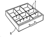
주식회사 대원에서 출원한 실용신안 93-8901호에서는, 도 10에 도시된 바와 같이, 책상 서랍(5)의 길이에 상응하는 길이를 가지는 칸막이 부재(1)들이 부재에 형성된 홈을 통해서 상호간에 서로 결합함으로서 서랍(5)의 내부에서 자가 직립하도록 구성된다. 이 진우가 출원한 공개실용신안 20-2016-0000584호에서는 플라스틱으로 이루어지고, 소정 길이로 끊어서 사용할 수 있는 서랍 분할용 칸막이를 제시한다. 이러한 자가 직립 방식은 조립이 쉽고 서랍의 길이와 칸막이의 길이가 달라도 사용할 수 있으며, 또한 손쉽게 칸막이 형태의 변형이 가능하다는 장점이 있지만, 서랍의 벽면에 지지되지 않기 때문에 견고하지 못하다는 단점이 있다. In Utility Model No. 93-8901 filed by Daewon Co., Ltd., as shown in FIG. 10 , the
조영행에게 허여된 등록실용신안 20-0477595호에서는 이러한 단점을 해소하기 위해서 도 11에서와 같이, 길이를 조절할 수 있으며 양단에 흡착판(40)이 부착된 길이 조절이 가능한 칸막이(10)을 개시한다. 이러한 방식은 길이 조절이 가능하고 견고한 부착이 가능하지만, 길이 조정이 원형 타공의 간격으로 이루어지므로 길이를 정확하게 맞지 않을 경우에는 부착과 설치가 어렵다는 문제가 있다. In order to solve this disadvantage in Registered Utility Model No. 20-0477595 granted to Young-haeng Cho, as shown in FIG. 11, the length can be adjusted and the length-
본 발명에서 해결하고자 하는 과제는 칸막이를 책상 서랍의 내측벽에 견고하게 고정할 수 있는 방법을 제공하는 것이다. An object to be solved by the present invention is to provide a method for securely fixing a partition to an inner wall of a desk drawer.
본 발명에서 해결하고자 하는 다른 과제는 칸막이의 길이와 책상 서랍의 길이를 일치시킬 수 있는 방법을 제공하는 것이다. Another object to be solved by the present invention is to provide a method capable of matching the length of the partition with the length of the desk drawer.
본 발명에서 해결하고자 하는 또 다른 과제는 서랍의 내측벽에 견고하게 고정되면서도 칸막이의 형상을 자유롭게 변형시킬 수 있는 새로운 칸막이 세트를 제공하는 것이다. Another object to be solved by the present invention is to provide a new set of partitions capable of freely changing the shape of the partition while being firmly fixed to the inner wall of the drawer.
상기와 같은 과제를 해결하기 위해서, In order to solve the above problems,
일면에 길이 방향을 따라서 톱니형 단면을 가지며, 길이에 따라 분할되어 서랍의 내측면에 고정되는 분할형 고정편; 및 a split-type fixing piece having a sawtooth-shaped cross-section along the longitudinal direction on one surface, divided along the length and fixed to the inner surface of the drawer; and
양면에 길이 방향을 따라서 톱니형 단면을 가지며, 길이에 따라 분할되어 상기 분할형 고정편 사이에 고정되는 분할형 칸막이편;a dividing type partition piece having a sawtooth-shaped cross section on both sides along the longitudinal direction, divided along the length and fixed between the divided fixing pieces;
을 포함하는 칸막이 세트를 제공한다. We provide a set of partitions that includes
본 발명에 있어서, 상기 분할형 고정편은 서랍의 내부 길이에 맞추어 절단할 수 있다. 상기 분할형 고정편은 손으로 절단하는 것이 가능하나, 매끄러운 절단면을 위해서 칼날로 절단하는 것이 가능하며, 절단의 편의를 위해서 톱니의 홈 모서리에 칼날 삽입용 홈이 형성되는 것이 바람직하다. In the present invention, the split-type fixing piece can be cut according to the inner length of the drawer. The split-type fixture can be cut by hand, but it is possible to cut with a blade for a smooth cutting surface, and it is preferable that a groove for inserting a blade is formed at the edge of the groove of the tooth for the convenience of cutting.
본 발명에 있어서, 상기 분할형 고정편의 일면에 형성되는 톱니는 절단이 편리하도록 삼각형 형상의 단면일 수 있다. 톱니 사이의 각도는 필요에 따라서 조절될 수 있으며, 바람직하게는 상기 삼각형은 직각 이등변 삼각형일 수 있다. In the present invention, the teeth formed on one surface of the split-type fixing piece may have a triangular cross-section for convenient cutting. The angle between the teeth may be adjusted as needed, and preferably, the triangle may be a right isosceles triangle.
본 발명에 있어서, 상기 분할형 고정편은 상면 및/또는 하면에는 절단시 길이를 확인할 수 있도록, 길이 나타내는 표시를 가질 수 있으며, 예를 들어, 톱니마다 1씩 증가하는 아라비아 일련번호 숫자를 표시할 수 있다. 예를 들어, 1, 2, 3, 4.....n이 표시될 수 있으며, 여기서 n은 정수일 수 있다. In the present invention, the split-type fixing piece may have a length indicating mark on the upper surface and/or lower surface so that the length can be checked when cutting, for example, an Arabic serial number increasing by 1 for each tooth. can For example, 1, 2, 3, 4.....n may be indicated, where n may be an integer.
본 발명의 실시에 있어서, 상기 분할형 고정편은 0.5 cm ~ 2 cm 간격으로 형성될 수 있으며, 바람직하게는 상면 및/또는 하면에 형성된 숫자를 이용해서 길이를 쉽게 알 수 있도록, 1 cm 간격으로 형성될 수 있다. In the practice of the present invention, the divided fixing pieces may be formed at 0.5 cm to 2 cm intervals, preferably at 1 cm intervals so that the length can be easily known using the numbers formed on the upper and/or lower surfaces. can be formed.
본 발명에 있어서, 상기 분할형 고정편은 고정 나사를 이용해서 서랍의 내측면에 고정될 수 있다. 상기 분할형 고정편은 나사 고정을 위해 나사홀이 형성될 수 있다. 상기 나사홈은 다양한 위치에 형성될 수 있지만, 톱니 사이의 홈에 형성되는 것이 바람직하다. 본 발명에 있어서, 상기 칸막이 세트에는 분할형 고정편을 고정하기 위한 나사를 더 포함할 수 있다. In the present invention, the split-type fixing piece may be fixed to the inner surface of the drawer using a fixing screw. The split-type fixing piece may be provided with a screw hole for screw fixing. The screw groove may be formed in various positions, but is preferably formed in the groove between the teeth. In the present invention, the partition set may further include a screw for fixing the split-type fixing piece.
본 발명에 있어서, 분할형 칸막이 편은 절단용 마디를 형성할 수 있도록 양면의 톱니가 대칭을 이룰 수 있다. 상기 일측의 톱니홈과 타측의 톱니홈이 만나는 마디에는 절단의 편의를 위해서 절단용 홈이 추가로 형성될 수 있다. In the present invention, the split-type partition piece can form a symmetrical teeth on both sides to form a cutting node. A cutting groove may be additionally formed at a node where the toothed groove of one side and the toothed groove of the other side meet for the convenience of cutting.
본 발명에 있어서, 상기 분할형 칸막이편의 톱니는 절단된 후 분할형 고정편의 톱니홈에 삽착될 수 있도록, 분할형 칸막이편의 측단의 형상이 분할형 고정편의 톱니홈의 형상에 상응할 수 있다. In the present invention, the shape of the side end of the split-type partition piece may correspond to the shape of the toothed groove of the split-type fixture so that the teeth of the split-type partition piece can be cut and then inserted into the toothed groove of the split-type fixture.
본 발명의 실시에 있어서, 분할형 칸막이편에는 양면에 정삼각형 형상의 톱니들이 대칭을 이루면서 형성되어, 분할된 칸막이편의 일 측단이 분할형 고정편의 톱니홈에 삽착될 수 있다. In the practice of the present invention, the split type partition piece is formed with symmetrical equilateral triangle-shaped teeth on both sides, so that one side end of the divided partition piece can be inserted into the serrated groove of the divided partition piece.
본 발명의 실시에 있어서, 분할형 칸막이편은 양단이 서랍의 내측면에 고정된 두 개의 분할형 고정편에 고정될 수 있다. 또한, 상기 분할형 칸막이편은 일측단은 서랍의 내측면에 고정된 분할형 고정편의 톱니형 홈에 삽착되어 고정되고, 다른 분할형 칸막이편에 고정될 수 있다. 또한, 분할형 칸막이편 일측단이 다른 분할형 칸막이편에 고정되고, 타측단도 또 다른 분할형 칸막이편에 고정될 수 있다. In the practice of the present invention, the split partitioning piece may be fixed to two split-type fixing pieces, both ends of which are fixed to the inner surface of the drawer. In addition, one end of the split-type partition piece may be inserted and fixed in the serrated groove of the split-type fixture fixed to the inner surface of the drawer, and fixed to the other partition-type partition piece. In addition, one end of the split-type partition piece may be fixed to the other split-type partition piece, and the other end may also be fixed to another split-type partition piece.
본 발명에 있어서, 상기 분할형 칸막이편은 상면 및/또는 하면에는 절단시 길이를 확인할 수 있도록, 길이 나타내는 표시를 가질 수 있으며, 예를 들어, 톱니마다 1씩 증가하는 아라비아 일련번호 숫자를 표시할 수 있다. 예를 들어, 1, 2, 3, 4.....n이 표시될 수 있으며, 여기서 n은 정수일 수 있다. In the present invention, the split type partition piece may have a length-indicating mark on the upper surface and/or lower surface so that the length can be checked when cutting, for example, an Arabic serial number increasing by 1 for each tooth. can For example, 1, 2, 3, 4.....n may be indicated, where n may be an integer.
본 발명의 실시에 있어서, 상기 분할형 칸막이편은 0.5 cm ~ 2 cm 간격으로 형성될 수 있으며, 바람직하게는 상면 및/또는 하면에 형성된 숫자를 이용해서 길이를 쉽게 알 수 있도록, 1 cm 간격으로 형성될 수 있다. In the practice of the present invention, the divided partition piece may be formed at 0.5 cm to 2 cm intervals, preferably at 1 cm intervals so that the length can be easily known using the numbers formed on the upper and/or lower surfaces. can be formed.
본 발명에 있어서, 상기 칸막이 세트는 분할형 지지편과 서랍의 내측면의 밀착성을 높이기 위해서 소정 길이 및 폭을 가지는 밀착편을 더 포함할 수 있다. 상기 밀착편의 두께는 분할형 지지편의 분할단위 보다 적으며, 바람직하게는 분할형 지지편의 분할 단위의 1/2, 1/3, 1/4, 1/5, 또는 1/10일 수 있다. In the present invention, the partition set may further include a contact piece having a predetermined length and width in order to increase the adhesion between the divided support piece and the inner surface of the drawer. The thickness of the close contact piece is less than the division unit of the divided support piece, and preferably 1/2, 1/3, 1/4, 1/5, or 1/10 of the division unit of the division type support piece.
본 발명에 있어서, 상기 밀착편은 지지편의 일면에 결합될 수 있으며, 또한 결합편과 함께 서랍내의 내면에 나사로 고정될 수 있다. 상기 밀착편에는 나사 고정을 위한 홀이 형성될 수 있다. In the present invention, the contact piece may be coupled to one surface of the support piece, and may be screwed to the inner surface of the drawer together with the coupling piece. A hole for screw fixing may be formed in the contact piece.
본 발명의 실시에 있어서, 상기 밀착편의 정면에는 지지편의 배면 또는 다른 밀착편의 배면에 형성된 홈에 결합할 수 있는 돌출부가 형성되며, 밀착편의 배면에는 다른 밀착편의 돌출부가 결합할 수 있는 홈이 형성된다. 상기 밀착편은 다른 밀착편과 함께 겹쳐져 두께를 조절할 수 있다.In the practice of the present invention, a protrusion capable of engaging with a groove formed on the rear surface of the support piece or on the rear surface of the other close contact piece is formed on the front surface of the close contact piece, and a groove capable of engaging the protrusion of the other contact piece is formed on the rear surface of the close contact piece. . The adhesion piece may be overlapped with other adhesion pieces to adjust the thickness.
본 발명에 있어서, 상기 분할형 지지편과 분할형 고정편은 플라스틱으로 이루어질 수 있으며, 예를 들어, ABS 수지, PS를 사용할 수 있다. In the present invention, the split-type support piece and the split-type fixing piece may be made of plastic, for example, ABS resin or PS may be used.
본 발명은 일 측면에서, The present invention in one aspect,
정면에는 상하 방향으로는 연장되는 삼각형 단면의 돌출부가 길이 방향을 따라서 반복적으로 형성되어 톱니형 단면을 형성하고, On the front side, a protrusion of a triangular cross section extending in the vertical direction is repeatedly formed along the longitudinal direction to form a sawtooth cross section,
여기서, 삼각형은 직각 이등변 삼각형이며, where the triangle is a right isosceles triangle,
톱니들 사이에는 절단용 홈이 형성되고, A cutting groove is formed between the teeth,
배면에는 길이 방향을 따라서 결합홈이 형성되며,A coupling groove is formed on the rear surface along the longitudinal direction,
상면 및/또는 하면에는 길이를 나타내는 표시되며,On the upper and/or lower surface, marks indicating the length,
소정 간격으로 나사용 홀이 형성된 것을 특징으로 하는 분할형 지지편을 제공한다. It provides a split-type support piece, characterized in that holes for screws are formed at predetermined intervals.
본 발명은 다른 일 측면에서, In another aspect, the present invention
소정 두께의 판재의 정면에 상하 방향으로는 연장되는 삼각형 단면의 정면 돌출부가 소정 간격으로 길이 방향으로 따라서 반복적으로 형성되고, 배면에 상하 방향으로 연장된 삼각형 단면의 후면 돌출부가 길이 방향을 따라서 소정 간격으로 반복적으로 형성되고, 상기 정면 돌출부와 후면 돌출부가 서로 대칭을 이루어 길이 방향을 따라서 마름모가 반복되는 형태의 단면을 가지며,Front projections of a triangular cross-section extending in the vertical direction are repeatedly formed along the longitudinal direction at predetermined intervals on the front surface of the plate material of a predetermined thickness, and the rear projections of the triangular cross-section extending in the vertical direction on the rear surface are formed at predetermined intervals along the longitudinal direction is repeatedly formed, and the front protrusion and the rear protrusion are symmetrical to each other and have a cross section in the form of repeating rhombus along the longitudinal direction,
상기 정면 돌출부 및/또는 후면 돌출부들 사이에는 절단용 홈이 형성되고, A cutting groove is formed between the front protrusion and/or the rear protrusion,
상기 마름모는 정사각형 마름모 형상인 것을 특징으로 하는 분할형 칸막이편을 제공한다. The rhombus provides a partition type partition piece, characterized in that it has a square rhombus shape.
본 발명에 있어서, 상기 서랍은 상부 개방된 직사각형 형태의 상자를 의미하는 것으로서, 책상 서랍, 옷장 서랍, 화장대 서랍, 수납 서랍 등에 사용할 수 있다. In the present invention, the drawer means a box of a rectangular shape with an open top, and can be used in a desk drawer, a wardrobe drawer, a dressing table drawer, a storage drawer, and the like.
본 발명에 따른 칸막이 세트는 서랍의 내면에 단단히 고정된 상태에서 자유롭게 칸을 조정할 수 있다. The divider set according to the present invention can freely adjust the compartments while being firmly fixed to the inner surface of the drawer.
특히, 연장된 분할형 지지편과 분할형 칸막이편이 있으며, 필요한 길이로 분할하여 다수의 서랍에 칸막이를 형성할 수 있게 된다. In particular, there are an extended split-type support piece and a split-type partition piece, and it is possible to form a partition in a plurality of drawers by dividing it to a required length.
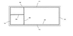
도 1은 본 발명에 따른 분할형 지지편 및 분할형 칸막이가 설치된 서랍의 내부를 보여주는 평면도이다.
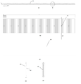
도 2는 본 발명에 따른 분할형 지지편을 보여주는 도면이다. 도 2a는 평면도이며, 도 2b는 정면도이며, 도 2c는 배면도이며, 도 2d는 측면도이며, 도 2e는 선분 aa'단면도이다.
도 3은 도 2a 원 부분의 확대도이다.
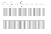
도 4는 본 발명에 따른 분할형 칸막이편을 보여주는 도면이다. 도 4a는 평면도이며, 도 4b는 정면도이며, 도 4c는 배면도이다.
도 5는 도 4a의 부분 확대도이다.
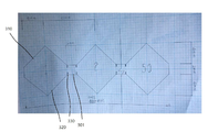
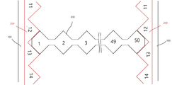
도 6은 본 발명의 분할형 지지편들 사이에 삽입된 분할형 칸막이편을 보여주는 평면도이다.
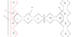
도 7은 본 발명의 분할형 지지편과 분할형 칸막이편 사이에 삽입된 다른 분할형 칸막이면의 평면도이다.
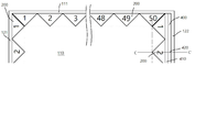
도 8은 본 발명의 일 실시에 따른 분할형 지지편과 서랍의 내측벽 사이에 틈새가 있을 경우, 밀착편이 삽입된 상태를 나타내는 평면도이다.
도 9는 도 8의 선분 CC' 단면을 보여주는 단면도이다.
도 10은 종래 일 실시에 따른 칸막이편을 보여주는 도면이다.
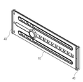
도 11은 종래 다른 일 실시에 따른 칸막이편을 보여주는 도면이다. 1 is a plan view showing the inside of a drawer in which a partition-type support piece and a partition-type partition according to the present invention are installed.
2 is a view showing a split-type support piece according to the present invention. Fig. 2A is a plan view, Fig. 2B is a front view, Fig. 2C is a rear view, Fig. 2D is a side view, and Fig. 2E is a cross-sectional view of line segment aa'.
Figure 3 is an enlarged view of the circle portion of Figure 2a.
4 is a view showing a partition type partition piece according to the present invention. Fig. 4A is a plan view, Fig. 4B is a front view, and Fig. 4C is a rear view.
FIG. 5 is a partially enlarged view of FIG. 4A .
6 is a plan view showing a partition type partition piece inserted between the division type support pieces of the present invention.
7 is a plan view of the back surface of another partition type partition inserted between the partition type support piece and the partition type partition piece of the present invention.
8 is a plan view illustrating a state in which a contact piece is inserted when there is a gap between the split type support piece and the inner wall of the drawer according to an embodiment of the present invention.
9 is a cross-sectional view showing a cross section of line segment CC′ of FIG. 8 .
10 is a view showing a partition piece according to an embodiment of the prior art.
11 is a view showing a partition piece according to another embodiment of the prior art.
이하, 실시예를 통해서 본 발명을 상세하게 설명한다. 하기 실시예는 본 발명을 예시한 것이며, 본 발명을 한정하기 위한 것은 아니다. Hereinafter, the present invention will be described in detail through examples. The following examples illustrate the present invention and are not intended to limit the present invention.
도 1에 도시된 바와 같이, 직사각형의 서랍(100)에는 서랍의 길이 방향을 따라서 연장되면서 서로 대향하는 한 쌍의 길이방향 내측벽(111, 112)와 서랍의 폭 방향을 따라서 연장되면서 서로 대향하는 한 쌍의 폭방향 내측벽(121, 122)을 가진다. As shown in FIG. 1 , the
서랍(100)의 길이방향 내측벽(111, 112)들과 폭방향 내측벽(121,122)들에는 각각 서랍의 길이방향 내측벽의 길이와 폭방향 내측벽의 길이에 맞추어 분할된 분할형 고정편(200)들이 고정된다. The lengthwise
서랍(100)의 내측벽들에 고정된 분할형 고정편(200)들의 사이에는 소정 길이로 분할된 분할형 칸막이(300)이 설치된다. 분할형 칸막이는 분할형 고정편 사이 뿐만 아니라, 분할형 고정편과 분할형 칸막이 사이나, 분할형 칸막이와 분할형 칸막이 사이에도 설치될 수 있다. A
도 2에 도시된 바와 같이, 분할형 고정편(200)은 통상적인 서랍의 내부 높이 에 해당하는 5~10 cm 범위의 높이를 가지며, 정면에는 상하 방향으로는 연장되는 삼각형 단면의 돌출부(210)가 길이 방향으로 따라서 반복적으로 형성된다.As shown in FIG. 2, the
분할형 고정편(200)의 배면은 평면이며, 중간에 길이 방향을 따라서 연장되는 낮고 긴 배면 결합 홈(220)이 형성된다. 상기 배면 결합홈(220)에는 필요시 분할형 고정편(200)과 서랍 내측벽 사이의 틈새를 메우는 밀착편(도시되지 않음)이 결합될 수 있다. The rear surface of the split-
분할형 고정편(200)의 중심부에는 나사의 통과를 위한 나사 관통홀(230)이 형성되어 있으며, 사용자는 나사(도시되지 않음)를 나사 관통홀(230)을 통해서 서랍(100)의 내측벽에 고정할 수 있다. A screw through
도 3에서 도시된 바와 같이, 분할형 고정편(200)의 돌출부는 밑변의 길이가 10 mm이며, 높이가 5 mm 인 삼각형이며, 내각이 45°인 이등변 삼각형 형태의 돌기가 반복적으로 형성되며, 이에 따라서 돌기 사이에는 내각이 90°인 홈이 반복적으로 형성되는 톱니형 돌기부를 이룬다. 삼각형 돌기사이의 톱니홈(202)는 절단의 편의를 위해서 고정편 절단홈(203)이 형성된다. 분할형 고정편(200)의 상면에는 돌기마다 1씩 증가하는 일련 번호가 기재되어 별도의 측정용 자가 없어도 분할형 고정편(200)의 길이를 알 수 있게 된다. As shown in FIG. 3, the protrusion of the
도 4에 도시된 바와 같이, 분할형 칸막이(300)은 분할형 고정편(200)의 높이에 상응하는 높이를 가지며, 소정 두께의 판재(301)에 정면에는 상하 방향으로는 연장되는 삼각형 단면의 정면 돌출부(310)가 길이 방향으로 따라서 반복적으로 형성된다. 분할형 칸막이(300)는 배면에도 상하 방향으로 연장된 삼각형 단면의 후면 돌출부(320)이 길이 방향을 따라서 반복적으로 형성된다. 분할형 칸막이(300)의 정면 돌출부(310)와 후면 돌출부(320)는 서로 대칭을 이루어 길이 방향을 따라서 마름모가 반복되는 형태의 단면을 이룬다. As shown in FIG. 4 , the
도 5에 도시된 바와 같이, 분할형 칸막이(300)는 판재(301)은 칸막이 강성을 위해서 2 mm 두께를 가지며, 정면 돌출부(310)는 밑변의 길이가 8 mm이며, 높이가 4 mm 이며, 내각이 45°인 이등변 삼각형 돌기가 2 mm 간격으로 이격되어 반복적으로 형성되며, 배면 돌출부(320)는 정면 돌출부(310)과 대칭을 이루면서 밑변의 길이가 8 mm이며, 높이가 4 mm 이며, 내각이 45°인 이등변 삼각형 돌기가 2 mm 간격으로 이격되어 반복적으로 형성되고, 정면 돌출부와 배면 돌출부가 대칭으로 형성되어, 정사각형 마름모가 연속적으로 반복된 형태를 이룬다. 5, the
정면 돌출부(310) 및 배면 돌출부(320)의 경사면과 판재(310)가 만나는 지점에는 절단을 위해서 지지편 절단홈(330)이 1 mm 깊이로 형성되며, 분할형 지지편(300)의 상면에는 마름모마다 1씩 증가하는 일련 번호가 기재되어 측정용 자가 없어도 분할형 지정편(300)의 분할된 길이를 알 수 있다.At the point where the inclined surfaces of the
도 6에서와 같이, 양단이 정사각형 마름모 형태를 이루는 분할형 칸막이편(300)은 90°의 직각 이등변 삼각형 형태의 홈을 가지는 분할형 지지편(200)사이에 고정되며, 분할형 지지편(200)이 서랍의 내부에 나사고정된 상태일 경우, 상부에서부터 슬라이딩 방식으로 삽입된다. As shown in FIG. 6, the divided
도 7에서와 같이, 양단이 정사각형 마름모 형태를 이루는 분할형 칸막이편(300)은 90°의 직각 이등변 삼각형 형태의 홈을 가지는 분할형 지지편(200)과 90°의 직각 이등변 삼각형 형태의 홈을 가지는 다른 분할형 칸막이편(300)에 지편에 고정된다. As shown in FIG. 7, the divided
도 8 및 도 9에서와 같이, 분할형 지지편이 n cm, 여기서, n은 양의 정수, 예를 들어 50이고, 서랍(100)의 길이 방향 내측벽 길이(111)가 n.m cm, 여기서, n 및 m은 양의 정수, 예를 들어, 50.4 cm인 경우, 길이 방향 내측벽(111)과 직각을 이루는 폭방향 내측벽(121, 122) 중에서 일측의 길이방향 내측벽(121)에는 분할형 지지편(200)을 밀착해서 고정되고, 타측의 길이방향 내측벽(122)에는 분할형 지지편(200)을 고정하기 위해서 밀착편(400)이 사용된다. 밀착편(400)은 2 mm 두께를 가지는 제1 밀착편(410)과 2 mm 두께를 가지는 제2 밀착편(420)가 사용되며, 제1 밀착편(410)의 전면에 형성된 제1 밀착편 돌기부(411)는 분할형 지지편(200)의 배면에 형성된 배면 결합홈(220)에 삽착되고, 제2 밀착편(420)의 전면에 형성된 제2 밀착편 돌기부(421)은 제1 밀착편(410)의 배면에 형성된 제1 밀착편 배면 결합홈(412)에 결합된다. 필요시, 제2 밀착편(420)의 배면에 형성된 제2 밀착편 배면 결합홈(422)에는 추가로 다른 밀착력은 돌기부가 결합될 수 있다.8 and 9 , the divided support piece is n cm, where n is a positive integer, for example 50, and the
분할형 지지편(200)과 제1 밀착편(410)과 제2 밀착편(420)은 대응되는 위치에 형성된 나사구멍을 관통하는 나사(도시되지 않음)를 이용해서 함께 서랍의 폭방향 내측벽(122)에 함께 고정된다. The
서랍의 내부 칸막이 구조를 변경하고자 할 경우에는, 서랍의 내측벽에 고정된 분할형 지지편(200)은 그대로 유지한 채, 분할형 칸막이편(300)들을 슬라이딩 방식으로 제거한 후, 이를 다른 위치에 삽입하거나, 다른 분할형 칸막이편(300)을 길이에 맞추어 분할한 후 삽입하는 방식으로 구조를 변경한다. If you want to change the structure of the inner partition of the drawer, remove the partition-
상기 실시예는 서랍을 일 예로서 예시하지만, 본 발명에 따른 내부 칸막이는 서랍과 같은 작은 수납 용품 뿐만 아니라, 컨테이너와 같은 대형 물품에도 사용할 수 있으며, 개방가능한 상부 커버가 있는 경우, 또는 상부 커버를 칸막이 설치 후에 별도가 형성하는 경우도 사용할 수 있다. The above embodiment exemplifies a drawer as an example, but the inner partition according to the present invention can be used not only for small storage items such as drawers, but also for large items such as containers, when there is an openable top cover, or with the top cover. It can also be used if it is formed separately after the partition is installed.
100: 서랍
200: 분할형 지지편
300: 분할형 칸막이편100: drawer
200: split support piece
300: split type partition piece
Claims (9)
양면에 길이 방향을 따라서 톱니형 단면을 가지며, 길이에 따라 분할되어 상기 분할형 고정편 사이에 고정되는 분할형 칸막이편;
을 포함하는 칸막이 세트.a split-type fixing piece having a sawtooth-shaped cross-section along the longitudinal direction on one surface, divided along the length and fixed to the inner surface of the drawer; and
a dividing type partition piece having a sawtooth-shaped cross section on both sides along the longitudinal direction, divided along the length and fixed between the divided fixing pieces;
Partition set containing.
상기 칸막이 세트는 분할형 고정편과 서랍의 내측벽 사이에 삽입되는 밀착편을 더 포함하는 칸막이 세트.According to claim 1,
The partition set further includes a close-fitting piece inserted between the partition-type fixing piece and the inner wall of the drawer.
상기 분할형 고정편 및 분할형 칸막이편은 톱니 사이에 절단용 홈을 가지는 것을 특징으로 하는 칸막이 세트.According to claim 1,
The divider set, characterized in that the divided fixed piece and the divided type divider has a groove for cutting between the teeth.
상기 분할형 칸막이편은 적어도 일측이 서랍의 내측면 또는 다른 분할형 고정편의 톱니에 삽입되어 고정되는 것을 특징으로 하는 칸막이 세트.7. The method according to any one of claims 1 to 6,
The partition type partition set, characterized in that at least one side is inserted and fixed into the inner surface of the drawer or the teeth of the other partition type partition piece.
여기서, 삼각형은 직각 이등변 삼각형이며,
톱니들 사이에는 절단용 홈이 형성되고,
배면에는 길이 방향을 따라서 결합홈이 형성되며,
상면 및/또는 하면에는 길이를 나타내는 표시되며,
소정 간격으로 나사용 홀이 형성된 것을 특징으로 하는 분할형 지지편.On the front side, a protrusion of a triangular cross section extending in the vertical direction is repeatedly formed along the longitudinal direction to form a sawtooth cross section,
where the triangle is a right isosceles triangle,
A cutting groove is formed between the teeth,
A coupling groove is formed on the rear surface along the longitudinal direction,
On the upper and/or lower surface, marks indicating the length,
Split type support piece, characterized in that holes for screws are formed at predetermined intervals.
상기 정면 돌출부 및/또는 후면 돌출부들 사이에는 절단용 홈이 형성되고,
상기 마름모는 정사각형 마름모 형상인 것을 특징으로 하는 분할형 칸막이편.
Front projections of a triangular cross section extending in the vertical direction are repeatedly formed along the longitudinal direction at predetermined intervals on the front surface of the plate material of a predetermined thickness, and the rear projections of the triangular cross section extending in the vertical direction on the rear surface are formed at predetermined intervals along the longitudinal direction is repeatedly formed, and the front protrusion and the rear protrusion are symmetrical to each other and have a cross section in the form of repeating rhombus along the longitudinal direction,
A cutting groove is formed between the front protrusion and/or the rear protrusion,
The rhombus is a partition type partition piece, characterized in that it has a square rhombus shape.
Priority Applications (1)
| Application Number | Priority Date | Filing Date | Title |
|---|---|---|---|
| KR1020200057882A KR102496576B1 (en) | 2020-05-14 | 2020-05-14 | Divider set |
Applications Claiming Priority (1)
| Application Number | Priority Date | Filing Date | Title |
|---|---|---|---|
| KR1020200057882A KR102496576B1 (en) | 2020-05-14 | 2020-05-14 | Divider set |
Publications (2)
| Publication Number | Publication Date |
|---|---|
| KR20210140970A true KR20210140970A (en) | 2021-11-23 |
| KR102496576B1 KR102496576B1 (en) | 2023-02-06 |
Family
ID=78695028
Family Applications (1)
| Application Number | Title | Priority Date | Filing Date |
|---|---|---|---|
| KR1020200057882A Active KR102496576B1 (en) | 2020-05-14 | 2020-05-14 | Divider set |
Country Status (1)
| Country | Link |
|---|---|
| KR (1) | KR102496576B1 (en) |
Citations (6)
| Publication number | Priority date | Publication date | Assignee | Title |
|---|---|---|---|---|
| US4838445A (en) * | 1988-02-17 | 1989-06-13 | Flambeau Corporation | Container including variable position compartment dividers |
| JPH0537155U (en) * | 1991-10-24 | 1993-05-21 | 日本軽金属株式会社 | Partition structure |
| JP3037574U (en) * | 1996-11-08 | 1997-05-20 | 株式会社アイビーム | Inner lid containers such as portable tool boxes |
| JPH11113662A (en) * | 1997-10-09 | 1999-04-27 | Yamashita Seisakusho:Kk | Storage box partitioning device |
| JP2002142889A (en) * | 2000-11-06 | 2002-05-21 | Yamaha Livingtec Corp | Drawer partition structure |
| KR20120028417A (en) * | 2010-09-14 | 2012-03-23 | 임옥진 | A section panel for collection box and section apparatus for the same |
-
2020
- 2020-05-14 KR KR1020200057882A patent/KR102496576B1/en active Active
Patent Citations (6)
| Publication number | Priority date | Publication date | Assignee | Title |
|---|---|---|---|---|
| US4838445A (en) * | 1988-02-17 | 1989-06-13 | Flambeau Corporation | Container including variable position compartment dividers |
| JPH0537155U (en) * | 1991-10-24 | 1993-05-21 | 日本軽金属株式会社 | Partition structure |
| JP3037574U (en) * | 1996-11-08 | 1997-05-20 | 株式会社アイビーム | Inner lid containers such as portable tool boxes |
| JPH11113662A (en) * | 1997-10-09 | 1999-04-27 | Yamashita Seisakusho:Kk | Storage box partitioning device |
| JP2002142889A (en) * | 2000-11-06 | 2002-05-21 | Yamaha Livingtec Corp | Drawer partition structure |
| KR20120028417A (en) * | 2010-09-14 | 2012-03-23 | 임옥진 | A section panel for collection box and section apparatus for the same |
Also Published As
| Publication number | Publication date |
|---|---|
| KR102496576B1 (en) | 2023-02-06 |
Similar Documents
| Publication | Publication Date | Title |
|---|---|---|
| US6913164B2 (en) | Adjustable drawer organizer | |
| US20030184199A1 (en) | Partitioning structure | |
| US3645486A (en) | Modular wall shelving | |
| PT1617745E (en) | System for attaching accessories to a shelf | |
| CA2404268A1 (en) | Drawers with adjustable drawer dividers | |
| US10925399B2 (en) | Modular organizer systems | |
| US4038790A (en) | Partition structure | |
| US4838445A (en) | Container including variable position compartment dividers | |
| US3582170A (en) | Display table | |
| US3279876A (en) | Storage cabinet construction | |
| CA2775300A1 (en) | Partition | |
| US3140791A (en) | Drawer divider support | |
| US3279642A (en) | Drawer divider or partition | |
| US20020180320A1 (en) | Hanging vertical organizer for file drawer | |
| US3862784A (en) | Front panel and partition holder for display shelf | |
| KR102496576B1 (en) | Divider set | |
| US11503908B2 (en) | Bracket for drawer slide | |
| US3294465A (en) | Desk with tambour | |
| JP2016214758A (en) | Drawer unit | |
| US5788346A (en) | Stand forming members | |
| US20050264147A1 (en) | Adaptable partitioned organizer | |
| US4244129A (en) | Adjustable card rack | |
| GB2092884A (en) | Improvements in or relating to shelving systems | |
| US20070001073A1 (en) | Bracket | |
| JPH0531951Y2 (en) |
Legal Events
| Date | Code | Title | Description |
|---|---|---|---|
| PA0109 | Patent application |
Patent event code: PA01091R01D Comment text: Patent Application Patent event date: 20200514 |
|
| PA0201 | Request for examination | ||
| E902 | Notification of reason for refusal | ||
| PE0902 | Notice of grounds for rejection |
Comment text: Notification of reason for refusal Patent event date: 20211116 Patent event code: PE09021S01D |
|
| PG1501 | Laying open of application | ||
| E701 | Decision to grant or registration of patent right | ||
| PE0701 | Decision of registration |
Patent event code: PE07011S01D Comment text: Decision to Grant Registration Patent event date: 20220503 |
|
| GRNT | Written decision to grant | ||
| PR0701 | Registration of establishment |
Comment text: Registration of Establishment Patent event date: 20230201 Patent event code: PR07011E01D |
|
| PR1002 | Payment of registration fee |
Payment date: 20230202 End annual number: 3 Start annual number: 1 |
|
| PG1601 | Publication of registration |