KR20210078118A - A mounting structure for supporting post of construction - Google Patents
A mounting structure for supporting post of construction Download PDFInfo
- Publication number
- KR20210078118A KR20210078118A KR1020190169864A KR20190169864A KR20210078118A KR 20210078118 A KR20210078118 A KR 20210078118A KR 1020190169864 A KR1020190169864 A KR 1020190169864A KR 20190169864 A KR20190169864 A KR 20190169864A KR 20210078118 A KR20210078118 A KR 20210078118A
- Authority
- KR
- South Korea
- Prior art keywords
- support
- vertical
- supporter
- horizontal
- supporters
- Prior art date
- Legal status (The legal status is an assumption and is not a legal conclusion. Google has not performed a legal analysis and makes no representation as to the accuracy of the status listed.)
- Ceased
Links
- 238000010276 construction Methods 0.000 title description 3
- 238000009434 installation Methods 0.000 claims abstract description 25
- 239000000463 material Substances 0.000 claims abstract description 6
- 238000000034 method Methods 0.000 claims description 4
- 230000000694 effects Effects 0.000 abstract description 2
- 230000015572 biosynthetic process Effects 0.000 abstract 1
- 230000008878 coupling Effects 0.000 abstract 1
- 238000010168 coupling process Methods 0.000 abstract 1
- 238000005859 coupling reaction Methods 0.000 abstract 1
- 230000006866 deterioration Effects 0.000 abstract 1
- 238000005516 engineering process Methods 0.000 abstract 1
- 238000009415 formwork Methods 0.000 description 3
- RYGMFSIKBFXOCR-UHFFFAOYSA-N Copper Chemical compound [Cu] RYGMFSIKBFXOCR-UHFFFAOYSA-N 0.000 description 2
- 229910052802 copper Inorganic materials 0.000 description 2
- 239000010949 copper Substances 0.000 description 2
- 238000010586 diagram Methods 0.000 description 1
- NJPPVKZQTLUDBO-UHFFFAOYSA-N novaluron Chemical compound C1=C(Cl)C(OC(F)(F)C(OC(F)(F)F)F)=CC=C1NC(=O)NC(=O)C1=C(F)C=CC=C1F NJPPVKZQTLUDBO-UHFFFAOYSA-N 0.000 description 1
- 230000002093 peripheral effect Effects 0.000 description 1
- 238000009416 shuttering Methods 0.000 description 1
Images
Classifications
-
- E—FIXED CONSTRUCTIONS
- E04—BUILDING
- E04G—SCAFFOLDING; FORMS; SHUTTERING; BUILDING IMPLEMENTS OR AIDS, OR THEIR USE; HANDLING BUILDING MATERIALS ON THE SITE; REPAIRING, BREAKING-UP OR OTHER WORK ON EXISTING BUILDINGS
- E04G7/00—Connections between parts of the scaffold
- E04G7/02—Connections between parts of the scaffold with separate coupling elements
-
- E—FIXED CONSTRUCTIONS
- E04—BUILDING
- E04G—SCAFFOLDING; FORMS; SHUTTERING; BUILDING IMPLEMENTS OR AIDS, OR THEIR USE; HANDLING BUILDING MATERIALS ON THE SITE; REPAIRING, BREAKING-UP OR OTHER WORK ON EXISTING BUILDINGS
- E04G7/00—Connections between parts of the scaffold
- E04G7/30—Scaffolding bars or members with non-detachably fixed coupling elements
- E04G7/301—Scaffolding bars or members with non-detachably fixed coupling elements for connecting bars or members which are parallel or in end-to-end relation
-
- E—FIXED CONSTRUCTIONS
- E04—BUILDING
- E04G—SCAFFOLDING; FORMS; SHUTTERING; BUILDING IMPLEMENTS OR AIDS, OR THEIR USE; HANDLING BUILDING MATERIALS ON THE SITE; REPAIRING, BREAKING-UP OR OTHER WORK ON EXISTING BUILDINGS
- E04G7/00—Connections between parts of the scaffold
- E04G7/30—Scaffolding bars or members with non-detachably fixed coupling elements
- E04G7/302—Scaffolding bars or members with non-detachably fixed coupling elements for connecting crossing or intersecting bars or members
- E04G7/306—Scaffolding bars or members with non-detachably fixed coupling elements for connecting crossing or intersecting bars or members the added coupling elements are fixed at several bars or members to connect
- E04G7/307—Scaffolding bars or members with non-detachably fixed coupling elements for connecting crossing or intersecting bars or members the added coupling elements are fixed at several bars or members to connect with tying means for connecting the bars or members
-
- E—FIXED CONSTRUCTIONS
- E04—BUILDING
- E04G—SCAFFOLDING; FORMS; SHUTTERING; BUILDING IMPLEMENTS OR AIDS, OR THEIR USE; HANDLING BUILDING MATERIALS ON THE SITE; REPAIRING, BREAKING-UP OR OTHER WORK ON EXISTING BUILDINGS
- E04G7/00—Connections between parts of the scaffold
- E04G7/30—Scaffolding bars or members with non-detachably fixed coupling elements
- E04G7/32—Scaffolding bars or members with non-detachably fixed coupling elements with coupling elements using wedges
Landscapes
- Engineering & Computer Science (AREA)
- Architecture (AREA)
- Mechanical Engineering (AREA)
- Civil Engineering (AREA)
- Structural Engineering (AREA)
- Forms Removed On Construction Sites Or Auxiliary Members Thereof (AREA)
Abstract
Description
본 발명은 시스템동바리용 수직서포트 설치구조에 관한 것으로, 특히 상이한 직경의 수직서포터들을 상하로 간편하고 안정되게 연결할 수 있음과 함께 수평재를 간편하게 연결할 수 있도록 개선된 구조의 시스템동바리용 수직서포트 설치구조에 관한 것이다.The present invention relates to a vertical support installation structure for a system supporter, and in particular, a vertical support installation structure for a system supporter of an improved structure so that vertical supporters of different diameters can be easily and stably connected up and down and horizontal members can be easily connected. it's about
최근의 건축현장에서, 거푸집을 설치하고 안정되게 하중을 지지하기 위하여 동바리를 부품화하여 간편하게 조립하여 설치하고 분해하기 쉽고, 작용하중은 안전하게 지지할 수 있도록 된 시스템동바리의 사용이 증가되고 있다.In recent construction sites, in order to install a formwork and stably support the load, the use of a system copper bar that is easy to assemble, install, and disassemble is easy to assemble and disassemble safely, and the use of a system copper bar is increasing in order to support the load stably.
이러한 시스템동바리는 거푸집널을 하측에서 지지하는 장선을 지지하고, 상부하중을 동바리에 전달하기 위하여 장선과 직각방향으로 설치하는 부재인 멍에를 서포트의 상단에 제공되는 "U-헤드 잭"으로 불리우는 멍에 지지구에 배치하여 거푸집을 지지하도록 된 가설구조물을 말한다.This system support supports the joist that supports the shuttering from the lower side, and the yoke, which is a member installed at right angles to the joist in order to transmit the upper load to the beam, is provided at the top of the support A yoke called "U-head jack" It refers to a temporary structure that is placed on a support to support the formwork.
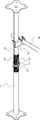
이러한 시스템동바리에서 거푸집과 그 위에 타설되는 콘크리트에 의한 하중을 안전하게 지지하도록 종래에는 도 1에 개략적으로 도시된 바와 같이, 하측 수직서포터(1)의 상부의 장공(2)이 형성된 외주면에 형성된 나사부(3)에 환형의 지지구(5)가 나사체결되고, 상기 하측 수직서포터(1)의 상단에 상측 수직서포터(6)를 삽입하고 상기 지지구(5) 위에 고정핀(7)을 상측 수직서포터(6)를 관통시켜 상기 지지구에 의해 지지되도록 연결하여 동바리용 수직서포터를 건축물의 층고에 맞춰서 시공하였다. 또한, 상측의 수직서포터(6)에는 별도로 두개의 클램프(8)를 사용하여 수평재(9)를 설치하였다. In order to safely support the load by the formwork and the concrete poured thereon in such a system dongbari, as schematically shown in FIG. 1 in the prior art, a screw part formed on the outer peripheral surface where the long hole 2 of the upper part of the lower vertical supporter 1 is formed ( 3), the
이러한 시스템동바리용의 수직서포트의 다른 예로서, 한국 공개특허공보 제10-2014-0125910호(공개일자 2014년10월30일)에는 외부지지관; 상단에 받침대가 형성되며, 하단부가 상기 외부지지관의 내부에 높이 조절 가능하게 삽입되어 결합되는 내부지지관; 및, 상기 내부지지관의 외주면에 끼워지며 작업발판을 설치가능하게 구비되고 상하부로 높이 조절 가능하게 장착됨으로써, 상기 내부지지관에 설치되는 작업발판의 위치를 조절하는 발판설치부;를 포함하는 건축용 동바리 구조물이 개시되어 있다.As another example of the vertical support for such a system dongbari, Korean Patent Application Laid-Open No. 10-2014-0125910 (published on October 30, 2014) has an external support pipe; an inner support tube having a pedestal formed on the upper end, and the lower end being inserted into the outer support tube so as to be height-adjustable and coupled thereto; and a scaffold installation part fitted to the outer circumferential surface of the inner support pipe to adjust the position of the working scaffold installed in the inner support pipe by being provided with a work scaffold to be installed and by being mounted so as to be adjustable in height up and down. The Dongbari structure is disclosed.
상기한 건축용 동바리 구조물은, 상부의 외주연에는 나사산이 형성되고 조절너트가 나사결합된 외부 지지관에, 상기 외부지지관의 내부에 내부지지관을 나사결합하여 연결하며, 발판설치부는 내부지지관의 외주면에 끼워지며, 높이조절가능하도록 내부지지관에 상하로 이격되게 관통형성된 복수의 조절공에 선택적으로 대응되게 배치되는 발판설치부의 통공과, 상기 통공과 상기 조절공에 조절핀을 삽입하여 높이를 조절하도록 되어 있다.The above-described construction dongbari structure is connected to an external support pipe having a screw thread formed on the outer periphery of the upper part and screwed with an adjustment nut, and screwed to connect an internal support pipe to the inside of the external support pipe, and the scaffold installation part is an internal support pipe The through hole of the footrest installation part fitted to the outer circumferential surface of the footrest installation part which is disposed to selectively correspond to a plurality of adjustment holes that are vertically spaced apart from the inner support pipe so that the height can be adjusted, and the adjustment pin is inserted into the through hole and the adjustment hole to increase the height is to be adjusted.
그러나, 상기한 종래의 건축용 동바리의 수직서포터의 높이를 건축물의 층고에 따라 조절하기 위하여 동일한 규격의 파이프로 된 발판설치부를 고정핀으로 연결설치하는데 따른 작업에 시간과 인력이 많이 소요되고, 상이한 직경의 파이프를 사용할 수 없는데 따른 설치작업에 제약이 있어 작업효율의 저하를 초래하는 문제가 있었다. However, in order to adjust the height of the vertical supporter of the conventional building dongbari according to the height of the building, it takes a lot of time and manpower to connect and install the scaffolding installation part made of the same pipe with a fixing pin, and different diameters There was a problem that caused a decrease in work efficiency due to restrictions on installation work due to the inability to use a pipe.
본 발명의 목적은 상기한 종래 기술의 문제점을 해결하기 위하여, 하부 수직서포터의 상단에 나사결합되는 연결관의 상면에 형성된 수직지지부의 내측이나 외측에 상부 수직서포터의 하단을 배치하여 연결하며, 상기 연결관의 측면에 형성된 복수개의 수평지지부에 수평재를 쐐기로 연결함으로써, 시스템동바리 설치작업을 매우 간편하게 수행할 수 있도록 개선된 시스템동바리용 수직서포트 설치구조를 제공하는 것이다.An object of the present invention is to connect the lower end of the upper vertical supporter by arranging the lower end of the upper vertical supporter on the inside or the outer side of the vertical support formed on the upper surface of the connector screwed to the upper end of the lower vertical supporter in order to solve the problems of the prior art, By connecting the horizontal member with a wedge to a plurality of horizontal support parts formed on the side of the connection pipe, it is to provide an improved vertical support installation structure for the system dongbari so that the system dongbari installation work can be performed very easily.
상기한 목적을 달성하기 위하여, 본 발명에 의한 시스템동바리용 수직서포트 설치구조는, 지면에 배치되고 하단에 지지판이 제공된 하측 수직서포터, 상기 하측 수직서포퍼의 상단에 결합되며 수평재를 결합하도록 된 지지구가 제공된 연결관, 상기 연결관의 상측에 제공되는 상측 수직서포터를 구비하는 시스템동바리용 수직서포트 설치구조에 있어서, In order to achieve the above object, the vertical support installation structure for the system dongbari according to the present invention is a lower vertical supporter disposed on the ground and provided with a support plate at the bottom, coupled to the upper end of the lower vertical supporter and to combine a horizontal member In the vertical support installation structure for system dongbari having a connecting pipe provided with earth, an upper vertical supporter provided on an upper side of the connecting pipe,
상기 연결관은 외주면에 형성된 나사부에 지지구가 나사결합방식으로 상하로 위치조정가능하게 제공되며,The connection pipe is provided so that the position can be adjusted up and down in a screw-coupled manner in a screw portion formed on the outer circumferential surface,
상기 지지구는 관형의 바디와, 상기 바디의 상면에서 환상으로 돌출, 연장되어 형성되어 상측 수직 서포터를 지지하도록 형성된 관형의 수직지지부, 상기 바디의 외측면에 복수개소에 수평으로 돌출되어 수평재를 결합하도록 체결공이 형성된 수평지지부들을 포함하는 것을 특징으로 하여 형성된다.The support includes a tubular body, a tubular vertical support portion formed to protrude and extend annularly from the upper surface of the body to support the upper vertical supporter, and horizontally protrude at a plurality of places on the outer surface of the body to combine the horizontal material It is formed, characterized in that it comprises a horizontal support portion is a fastening hole is formed.
상기 지지구의 바디 상면에 형성된 수직지지부의 내측에 상대적을 작은 직경의 상측 수직서포터와, 상기 수직지지부의 외측에 상대적으로 큰 직경을 갖는 상측 수직서포터들 중에서 선택하여 상이한 직경의 상측 수직서포터를 사용하도록 구성된다.Select from among upper vertical supporters having a relatively small diameter on the inside of the vertical support formed on the upper surface of the body of the support and upper vertical supporters having a relatively large diameter on the outside of the vertical support to use the upper vertical supporters of different diameters. is composed
상기 지지부의 측면에 형성된 수평지지부들 각각에는 수평재의 "ㄷ"자 형상으로 된 단부를 끼우고, 상기 단부에 형성된 체결공에 쐐기를 끼워 상기 지지구의 바디의 수직의 외측면에 대하여 수평재의 단부가 밀착되도록 결합하도록 구성된다.The end of the horizontal member with respect to the vertical outer surface of the body of the support body by inserting the end of the "C" shape of the horizontal member into each of the horizontal support parts formed on the side of the support part, and inserting a wedge into the fastening hole formed at the end It is configured to be coupled to be in close contact.
본 발명에 의한 시스템동바리용 수직서포트 설치구조는 외측면에 나사가 형성된 연결관에 나사체결방식으로 상하 높이조정가능하게 지지구를 설치하고, 그 지지부의 상면에 형성된 수직지지부의 내외측에 상이한 직경의 파이프들을 상측 수직서포터로서 현장의 필요 또는 상황에 따라 작업자가 선택하여 사용할 수 있으므로 작업효율성이 향상되고, 종래 상측의 수직서포터를 고정핀을 사용하여 관통공을 통해 고정하지 않게 되므로 고정핀과 고정핀 지지구를 사용하지 않아 부품 수를 감소하여 부품비용을 절감할 수 있고, 하측의 수직서포터의 상부에 장공을 형성하지 않으므로 강성 저하를 방지할 수 있고, 수평재를 수평지지부에 쐐기로 간편하게 결합하여 설치할 수 있어서 수평재의 설치작업을 효율적이고 간편하게 수행할 수 있는 효과가 있다. The vertical support installation structure for system dongbari according to the present invention installs a support for up-and-down height adjustment in a screw fastening method on a connection pipe having a screw formed on the outer surface, and has different diameters on the inside and outside of the vertical support formed on the upper surface of the support part As the upper vertical supporter can be selected and used by the operator according to the needs or circumstances of the site, work efficiency is improved, and the conventional upper vertical supporter is not fixed through a through hole using a fixing pin, so it is fixed with a fixing pin By not using a pin support, it is possible to reduce the cost of parts by reducing the number of parts, and since a long hole is not formed in the upper part of the lower vertical supporter, it is possible to prevent a decrease in rigidity. Because it can be installed, there is an effect that the installation work of the horizontal member can be performed efficiently and conveniently.
도 1은 종래 상측과 하측의 서포터들을 연결하여 동바리용 수직서포터를 설치하는 것을 보여주는 개략적인 사시도.
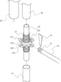
도 2는 본 발명에 의한 시스템동바리용 수직서포트 설치를 위해 지지구를 구비한 연결관을 상측과 하측의 수직서포터에 연결하는 것을 보여주는 사시도.
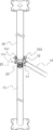
도 3은 도 2에서 연결관의 지지구에 형성된 수직지지부 외측에 상대적으로 큰 직경의 상측 수직서포터를 배치하고, 상기 지지구의 수평지지부에는 수평재를 연결한 것을 보여주는 사용상태도.
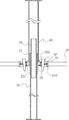
도 4는 도 3의 개략적인 단면도.1 is a schematic perspective view showing a conventional vertical supporter for Dongbari by connecting upper and lower supporters.
Figure 2 is a perspective view showing a connection pipe having a support for the installation of the vertical support for the system dongbari according to the present invention to the upper and lower vertical supporters.
FIG. 3 is a state diagram showing that an upper vertical supporter having a relatively large diameter is disposed on the outside of the vertical support formed in the support of the connector in FIG. 2, and a horizontal member is connected to the horizontal support of the support.
Fig. 4 is a schematic cross-sectional view of Fig. 3;
이하에서는 본 발명의 실시예를 도시한 첨부 도면을 참고하여 본 발명을 보다 상세히 설명하기로 한다.Hereinafter, the present invention will be described in more detail with reference to the accompanying drawings showing embodiments of the present invention.
도 2 내지 4에 있어서, 본 발명에 의한 시스템동바리용 수직서포트 설치구조는 지면에 배치되고 하단에 지지판(11)이 제공된 하측 수직서포터(10), 상기 하측 수직서포터(10)의 상단에 결합되며 수평재를 결합하도록 된 지지구(25)가 제공된 연결관(20), 상기 연결관의 상측에 제공되는 상측 수직서포터(30,30')를 포함한다.2 to 4, the vertical support installation structure for system dongbari according to the present invention is disposed on the ground and coupled to the upper end of the lower
상기 연결관(20)은 외주면에 나사부(21)가 반경방향 외측에 돌출되어 형성되어 있으며, 상기 나사부(21)에는 지지구(25)가 나사결합방식으로 상하로 위치조정가능하게 제공된다.The connecting
상기 지지구(25)는 관형으로 내측면에 나사가 형성된 바디(251)와, 상기 바디의 상면에서 환상으로 돌출, 연장되어 형성된 관형의 수직지지부(252), 상기 바디(251)의 외측면에 복수개소에서 반경방향 외측으로, 수평으로 돌출되어 형성되고 체결공(254)이 형성된 수평지지부(253)들을 포함하여 구성된다. The
본 발명에 따라, 상기 하측 수직서포터(10)의 상부 내측면에 나사가 형성되어 상기 연결관(20)을 삽입하여 나사부(21)를 체결하여 연결관을 설치한다.According to the present invention, a screw is formed on the upper inner surface of the lower
상기 연결관(20)에 제공된 지지구(25)의 상면에 상방향으로 연장되어 형성된 관형의 수직지지부(252)의 내측 또는 외측에 상측 수직서포터(30,30')가 배치되어 지지되며, 상기 지지부(25)의 측면에 형성된 수평지지부(253)들 각각에는 수평재(50)의 "ㄷ"자 형상으로 된 단부(51)를 끼우고, 상기 단부에 형성된 체결공에 쐐기(52)를 끼워 결합한다. 또한, 상기 바디(251)의 외측면은 수직면으로 형성되어서, 수평지지부(253)에 쐐기로 결합되는 수평재(50)의 단부가 바디의 외측면에 대하여 밀착되어 수평재가 외부 충격에 대하여 보다 안정되게 유지될 수 있게 된다.Upper
도 4에서 상기 수직지지부(252)의 내측에 상측 수직서포터(30)가 배치된 것이 도시되어 있으나, 수직지지부의 외측에도 상기 상측 수직서포터(30) 보다 상대적으로 큰 직경의 상측 수직서포터(30')를 배치하여 사용할 수도 있다. In FIG. 4 , the upper
즉, 지지부(25)의 상측에는 수직지지부(252)의 내외측들 각각에 배치될 수 있는 상측 수직서포터(30,30')로서 두가지 직경의 파이프를 사용할 수 있게 되므로, 작업현장에서 작업자의 작업 편의성이 향상된다. 도시된 실시예에서 수직지지부(252)의 상방향으로 돌출된 길이가 작게 표시되어 있으나, 실제로는 상측 수직서포터를 안정되게 배치하도록 보다 더 길게 형성될 수 있음은 쉽게 이해할 수 있을 것이다. 상기 상측 수직서포터(30)의 외경은 수직지지부(252)의 내경 보다 허용공차 범위에서 작게 형성되는 한편, 상기 바디(251) 상면에서 수직지지부(252)의 외측으로의 간격은 내경이 수직지지부(252)의 외경보다 허용공차 범위에서 더 크게 형성된 수직서포터(30')의 두께 보다 더 크게 형성되어야 한다.That is, since it is possible to use a pipe of two diameters as upper
본 발명에 의한 시스템동바리용 수직서포트 설치구조는 외측면에 나사가 형성된 연결관에 나사체결방식으로 상하 높이조정가능하게 지지구를 설치하고, 그 지지부의 상면에 형성된 수직지지부의 내외측에 상이한 직경의 파이프들을 상측 수직서포터로서 현장의 필요 또는 상황에 따라 작업자가 선택하여 사용할 수 있으므로 작업효율성이 향상되고, 종래 상측의 수직서포터를 고정핀을 사용하여 관통공을 통해 고정하지 않게 되므로 수직서포토의 관통공 형성 작업이 필요없고, 고정핀과 고정핀 지지구를 사용하지 않아 부품 수를 감소하여 부품비용을 절감할 수 있고, 하측의 수직서포터의 상부에 장공을 형성하지 않으므로 강성 저하를 방지할 수 있으며, 수평지지부에 수평재의 단부를 쐐기로 간편하게 결합하여 설치할 수 있어서 수평재의 설치작업을 효율적이고 간편하게 수행할 수 있게 된다. The vertical support installation structure for system dongbari according to the present invention installs a support for up-and-down height adjustment in a screw fastening method on a connection pipe having a screw formed on the outer surface, and has different diameters on the inside and outside of the vertical support formed on the upper surface of the support part As the upper vertical supporter can be selected and used by the operator according to the needs or circumstances of the field, work efficiency is improved, and the conventional upper vertical supporter is not fixed through a through hole using a fixing pin. There is no need to form a through hole, and the number of parts can be reduced by reducing the number of parts by not using a fixing pin and a fixing pin supporter, and a long hole is not formed in the upper part of the lower vertical supporter, so a decrease in rigidity can be prevented. In addition, since the end of the horizontal member can be easily combined with a wedge to the horizontal support, the installation of the horizontal member can be performed efficiently and conveniently.
본 발명은 시스템동바리의 수직서포트를 연장하여 설치하고 수직서포터에 수평재를 설치하도록 이용될 수 있다.The present invention can be used to extend and install the vertical support of the system dongbari and to install the horizontal member on the vertical supporter.
10 : (하측) 수직서포터 11 : 지지판
20 : 연결관 21 : 나사부
25 : 지지구 251 : 바디
252 : 수직지지부 253 : 수평지지부
254 : 체결공 30, 30' : 상측 수직서포터
50 : 수평재 51 : 단부
52 : 쐐기10: (lower side) vertical supporter 11: support plate
20: connector 21: threaded part
25: support 251: body
252: vertical support 253: horizontal support
254:
50: horizontal member 51: end
52 : wedge
Claims (3)
상기 연결관(20)은 외주면에 형성된 나사부(21)에 지지구(25)가 나사결합방식으로 상하로 위치조정가능하게 제공되며,
상기 지지구(25)는 관형의 바디(251)와, 상기 바디의 상면에서 환상으로 돌출, 연장되어 형성되어 상측 수직 서포터(30,30')를 지지하도록 형성된 관형의 수직지지부(252), 상기 바디(251)의 외측면에 복수개소에 수평으로 돌출되어 수평재를 결합하도록 체결공(254)이 형성된 수평지지부(253)들을 포함하는 것을 특징으로 하는 시스템동바리용 수직서포트 설치구조.
A lower vertical supporter 10 disposed on the ground and provided with a support plate 11 at the lower end, a connector 20 coupled to the upper end of the lower vertical supporter 10 and provided with a support 25 to couple a horizontal member, In the vertical support installation structure for the system dongbari having the upper vertical supporters (30, 30') provided on the upper side of the connection pipe,
The connecting pipe 20 is provided with a support 25 on the screw portion 21 formed on the outer circumferential surface so that the position can be adjusted up and down in a screwing manner,
The support 25 includes a tubular body 251 and a tubular vertical support part 252 formed to protrude and extend annularly from the upper surface of the body to support the upper vertical supporters 30 and 30', the A vertical support installation structure for system dongbari, characterized in that it includes horizontal support portions 253 having fastening holes 254 formed so as to horizontally protrude at a plurality of places on the outer surface of the body 251 to couple the horizontal material.
상기 지지구(25)의 바디(251) 상면에 형성된 수직지지부(252)의 내측에 상대적을 작은 직경의 상측 수직서포터(30)와, 상기 수직지지부(252)의 외측에 상대적으로 큰 직경을 갖는 상측 수직서포터(30')들 중에서 선택하여 상이한 직경의 상측 수직서포터를 사용하도록 된 것을 특징으로 하는 시스템동바리용 수직서포트 설치구조.
The method of claim 1,
An upper vertical supporter 30 having a relatively small diameter on the inside of the vertical support part 252 formed on the upper surface of the body 251 of the support 25, and a relatively large diameter on the outside of the vertical support part 252. A vertical support installation structure for system dongbari, characterized in that the upper vertical supporters of different diameters are selected from among the upper vertical supporters 30'.
상기 지지부(25)의 측면에 형성된 수평지지부(253)들 각각에는 수평재(50)의 "ㄷ"자 형상으로 된 단부(51)를 끼우고, 상기 단부에 형성된 체결공(254)에 쐐기(52)를 끼워 상기 지지구(25)의 바디(251)의 수직의 외측면에 대하여 수평재의 단부가 밀착되도록 결합하도록 된 것을 특징으로 하는 시스템동바리용 수직서포트 설치구조.
3. The method of claim 1 or 2,
Each of the horizontal support parts 253 formed on the side surface of the support part 25 is fitted with a "C"-shaped end 51 of the horizontal member 50, and a wedge 52 is inserted into the fastening hole 254 formed at the end. ) by inserting a vertical support installation structure for system support, characterized in that the end of the horizontal member is coupled to the vertical outer surface of the body (251) of the support (25) so as to be in close contact with each other.
Priority Applications (1)
| Application Number | Priority Date | Filing Date | Title |
|---|---|---|---|
| KR1020190169864A KR20210078118A (en) | 2019-12-18 | 2019-12-18 | A mounting structure for supporting post of construction |
Applications Claiming Priority (1)
| Application Number | Priority Date | Filing Date | Title |
|---|---|---|---|
| KR1020190169864A KR20210078118A (en) | 2019-12-18 | 2019-12-18 | A mounting structure for supporting post of construction |
Publications (1)
| Publication Number | Publication Date |
|---|---|
| KR20210078118A true KR20210078118A (en) | 2021-06-28 |
Family
ID=76607819
Family Applications (1)
| Application Number | Title | Priority Date | Filing Date |
|---|---|---|---|
| KR1020190169864A Ceased KR20210078118A (en) | 2019-12-18 | 2019-12-18 | A mounting structure for supporting post of construction |
Country Status (1)
| Country | Link |
|---|---|
| KR (1) | KR20210078118A (en) |
Cited By (3)
| Publication number | Priority date | Publication date | Assignee | Title |
|---|---|---|---|---|
| KR102441154B1 (en) * | 2021-09-23 | 2022-09-08 | 한음기업(주) | Posts for supporting formwork |
| EP4325000A1 (en) * | 2022-04-26 | 2024-02-21 | CBR Rock Master Spólka z o.o. Sp. k. | Cushioning safety post |
| US20250122735A1 (en) * | 2023-10-17 | 2025-04-17 | Kokosing Construction Company, Inc. | Work platform |
Citations (1)
| Publication number | Priority date | Publication date | Assignee | Title |
|---|---|---|---|---|
| KR20140125910A (en) | 2013-04-18 | 2014-10-30 | 재단법인 포항산업과학연구원 | Support structure of building |
-
2019
- 2019-12-18 KR KR1020190169864A patent/KR20210078118A/en not_active Ceased
Patent Citations (1)
| Publication number | Priority date | Publication date | Assignee | Title |
|---|---|---|---|---|
| KR20140125910A (en) | 2013-04-18 | 2014-10-30 | 재단법인 포항산업과학연구원 | Support structure of building |
Cited By (3)
| Publication number | Priority date | Publication date | Assignee | Title |
|---|---|---|---|---|
| KR102441154B1 (en) * | 2021-09-23 | 2022-09-08 | 한음기업(주) | Posts for supporting formwork |
| EP4325000A1 (en) * | 2022-04-26 | 2024-02-21 | CBR Rock Master Spólka z o.o. Sp. k. | Cushioning safety post |
| US20250122735A1 (en) * | 2023-10-17 | 2025-04-17 | Kokosing Construction Company, Inc. | Work platform |
Similar Documents
| Publication | Publication Date | Title |
|---|---|---|
| JP3224040U (en) | Height adjustable bracket and support device using the bracket | |
| CN104594628B (en) | Cast-in-place concrete contignation form bracing system and construction method | |
| CN107975251B (en) | Assembled building wallboard joint support device | |
| KR101821152B1 (en) | Electric pole for easily adjusting height of power distribution line | |
| KR102361789B1 (en) | Supporter for installating horizontal member of supporting system | |
| KR100842061B1 (en) | Jack support | |
| KR20140125910A (en) | Support structure of building | |
| CN210342692U (en) | Single-point embedded part inclined strut device of aluminum alloy template system | |
| KR200384393Y1 (en) | Jack support pipe for construction | |
| KR20110007618U (en) | Drop head supporter of supporting post for construction | |
| CN110761299B (en) | Bracket for installing steel support on purlin of foundation pit and its construction method | |
| KR20060037137A (en) | Spacing device of building support | |
| KR20180082104A (en) | A support pipe with clamp for construction | |
| CN218492725U (en) | Vertical butt joint adjusting device of steel construction | |
| CN214144690U (en) | Center drawing plate device for slip form construction | |
| CN217947492U (en) | Pre-buried landing leg device of fishtail plate-type tower machine basis | |
| US20240151052A1 (en) | Mounting support for element | |
| CN115726588A (en) | Secondary pre-buried installation positioning device and method for building water supply and drainage sleeve | |
| KR101996559B1 (en) | The system supporting post for supporting hunch | |
| CN117513738A (en) | A high-altitude cantilevered structural steel formwork support system and construction method | |
| KR101545865B1 (en) | Building support | |
| CN110700306B (en) | Adjusting device for installing anchor bolt cage of wind driven generator and construction method of adjusting device | |
| JP2022189426A (en) | Support structure and fixing device for support pipe used therefor | |
| KR100482272B1 (en) | A supprot pipe for construction | |
| JP2010070946A (en) | Bolt and device for supporting floor |
Legal Events
| Date | Code | Title | Description |
|---|---|---|---|
| PA0109 | Patent application |
Patent event code: PA01091R01D Comment text: Patent Application Patent event date: 20191218 |
|
| PA0201 | Request for examination | ||
| PE0902 | Notice of grounds for rejection |
Comment text: Notification of reason for refusal Patent event date: 20210219 Patent event code: PE09021S01D |
|
| PG1501 | Laying open of application | ||
| E601 | Decision to refuse application | ||
| PE0601 | Decision on rejection of patent |
Patent event date: 20210831 Comment text: Decision to Refuse Application Patent event code: PE06012S01D Patent event date: 20210219 Comment text: Notification of reason for refusal Patent event code: PE06011S01I |