KR20200097825A - Method for processing image on basis of intra prediction mode and apparatus therefor - Google Patents
Method for processing image on basis of intra prediction mode and apparatus therefor Download PDFInfo
- Publication number
- KR20200097825A KR20200097825A KR1020207023177A KR20207023177A KR20200097825A KR 20200097825 A KR20200097825 A KR 20200097825A KR 1020207023177 A KR1020207023177 A KR 1020207023177A KR 20207023177 A KR20207023177 A KR 20207023177A KR 20200097825 A KR20200097825 A KR 20200097825A
- Authority
- KR
- South Korea
- Prior art keywords
- intra prediction
- prediction mode
- divided
- unit
- block
- Prior art date
Links
Images


Classifications
-
- H—ELECTRICITY
- H04—ELECTRIC COMMUNICATION TECHNIQUE
- H04N—PICTORIAL COMMUNICATION, e.g. TELEVISION
- H04N19/00—Methods or arrangements for coding, decoding, compressing or decompressing digital video signals
- H04N19/10—Methods or arrangements for coding, decoding, compressing or decompressing digital video signals using adaptive coding
- H04N19/134—Methods or arrangements for coding, decoding, compressing or decompressing digital video signals using adaptive coding characterised by the element, parameter or criterion affecting or controlling the adaptive coding
- H04N19/157—Assigned coding mode, i.e. the coding mode being predefined or preselected to be further used for selection of another element or parameter
- H04N19/159—Prediction type, e.g. intra-frame, inter-frame or bidirectional frame prediction
-
- H—ELECTRICITY
- H04—ELECTRIC COMMUNICATION TECHNIQUE
- H04N—PICTORIAL COMMUNICATION, e.g. TELEVISION
- H04N19/00—Methods or arrangements for coding, decoding, compressing or decompressing digital video signals
- H04N19/10—Methods or arrangements for coding, decoding, compressing or decompressing digital video signals using adaptive coding
- H04N19/102—Methods or arrangements for coding, decoding, compressing or decompressing digital video signals using adaptive coding characterised by the element, parameter or selection affected or controlled by the adaptive coding
- H04N19/103—Selection of coding mode or of prediction mode
- H04N19/107—Selection of coding mode or of prediction mode between spatial and temporal predictive coding, e.g. picture refresh
-
- H—ELECTRICITY
- H04—ELECTRIC COMMUNICATION TECHNIQUE
- H04N—PICTORIAL COMMUNICATION, e.g. TELEVISION
- H04N19/00—Methods or arrangements for coding, decoding, compressing or decompressing digital video signals
- H04N19/10—Methods or arrangements for coding, decoding, compressing or decompressing digital video signals using adaptive coding
- H04N19/102—Methods or arrangements for coding, decoding, compressing or decompressing digital video signals using adaptive coding characterised by the element, parameter or selection affected or controlled by the adaptive coding
- H04N19/103—Selection of coding mode or of prediction mode
- H04N19/11—Selection of coding mode or of prediction mode among a plurality of spatial predictive coding modes
-
- H—ELECTRICITY
- H04—ELECTRIC COMMUNICATION TECHNIQUE
- H04N—PICTORIAL COMMUNICATION, e.g. TELEVISION
- H04N19/00—Methods or arrangements for coding, decoding, compressing or decompressing digital video signals
- H04N19/10—Methods or arrangements for coding, decoding, compressing or decompressing digital video signals using adaptive coding
- H04N19/102—Methods or arrangements for coding, decoding, compressing or decompressing digital video signals using adaptive coding characterised by the element, parameter or selection affected or controlled by the adaptive coding
- H04N19/119—Adaptive subdivision aspects, e.g. subdivision of a picture into rectangular or non-rectangular coding blocks
-
- H—ELECTRICITY
- H04—ELECTRIC COMMUNICATION TECHNIQUE
- H04N—PICTORIAL COMMUNICATION, e.g. TELEVISION
- H04N19/00—Methods or arrangements for coding, decoding, compressing or decompressing digital video signals
- H04N19/10—Methods or arrangements for coding, decoding, compressing or decompressing digital video signals using adaptive coding
- H04N19/102—Methods or arrangements for coding, decoding, compressing or decompressing digital video signals using adaptive coding characterised by the element, parameter or selection affected or controlled by the adaptive coding
- H04N19/124—Quantisation
-
- H—ELECTRICITY
- H04—ELECTRIC COMMUNICATION TECHNIQUE
- H04N—PICTORIAL COMMUNICATION, e.g. TELEVISION
- H04N19/00—Methods or arrangements for coding, decoding, compressing or decompressing digital video signals
- H04N19/10—Methods or arrangements for coding, decoding, compressing or decompressing digital video signals using adaptive coding
- H04N19/102—Methods or arrangements for coding, decoding, compressing or decompressing digital video signals using adaptive coding characterised by the element, parameter or selection affected or controlled by the adaptive coding
- H04N19/132—Sampling, masking or truncation of coding units, e.g. adaptive resampling, frame skipping, frame interpolation or high-frequency transform coefficient masking
-
- H—ELECTRICITY
- H04—ELECTRIC COMMUNICATION TECHNIQUE
- H04N—PICTORIAL COMMUNICATION, e.g. TELEVISION
- H04N19/00—Methods or arrangements for coding, decoding, compressing or decompressing digital video signals
- H04N19/10—Methods or arrangements for coding, decoding, compressing or decompressing digital video signals using adaptive coding
- H04N19/169—Methods or arrangements for coding, decoding, compressing or decompressing digital video signals using adaptive coding characterised by the coding unit, i.e. the structural portion or semantic portion of the video signal being the object or the subject of the adaptive coding
- H04N19/17—Methods or arrangements for coding, decoding, compressing or decompressing digital video signals using adaptive coding characterised by the coding unit, i.e. the structural portion or semantic portion of the video signal being the object or the subject of the adaptive coding the unit being an image region, e.g. an object
- H04N19/176—Methods or arrangements for coding, decoding, compressing or decompressing digital video signals using adaptive coding characterised by the coding unit, i.e. the structural portion or semantic portion of the video signal being the object or the subject of the adaptive coding the unit being an image region, e.g. an object the region being a block, e.g. a macroblock
-
- H—ELECTRICITY
- H04—ELECTRIC COMMUNICATION TECHNIQUE
- H04N—PICTORIAL COMMUNICATION, e.g. TELEVISION
- H04N19/00—Methods or arrangements for coding, decoding, compressing or decompressing digital video signals
- H04N19/50—Methods or arrangements for coding, decoding, compressing or decompressing digital video signals using predictive coding
- H04N19/593—Methods or arrangements for coding, decoding, compressing or decompressing digital video signals using predictive coding involving spatial prediction techniques
-
- H—ELECTRICITY
- H04—ELECTRIC COMMUNICATION TECHNIQUE
- H04N—PICTORIAL COMMUNICATION, e.g. TELEVISION
- H04N19/00—Methods or arrangements for coding, decoding, compressing or decompressing digital video signals
- H04N19/60—Methods or arrangements for coding, decoding, compressing or decompressing digital video signals using transform coding
-
- H—ELECTRICITY
- H04—ELECTRIC COMMUNICATION TECHNIQUE
- H04N—PICTORIAL COMMUNICATION, e.g. TELEVISION
- H04N19/00—Methods or arrangements for coding, decoding, compressing or decompressing digital video signals
- H04N19/70—Methods or arrangements for coding, decoding, compressing or decompressing digital video signals characterised by syntax aspects related to video coding, e.g. related to compression standards
-
- H—ELECTRICITY
- H04—ELECTRIC COMMUNICATION TECHNIQUE
- H04N—PICTORIAL COMMUNICATION, e.g. TELEVISION
- H04N19/00—Methods or arrangements for coding, decoding, compressing or decompressing digital video signals
- H04N19/80—Details of filtering operations specially adapted for video compression, e.g. for pixel interpolation
- H04N19/82—Details of filtering operations specially adapted for video compression, e.g. for pixel interpolation involving filtering within a prediction loop
-
- H—ELECTRICITY
- H04—ELECTRIC COMMUNICATION TECHNIQUE
- H04N—PICTORIAL COMMUNICATION, e.g. TELEVISION
- H04N19/00—Methods or arrangements for coding, decoding, compressing or decompressing digital video signals
- H04N19/90—Methods or arrangements for coding, decoding, compressing or decompressing digital video signals using coding techniques not provided for in groups H04N19/10-H04N19/85, e.g. fractals
- H04N19/91—Entropy coding, e.g. variable length coding [VLC] or arithmetic coding
Abstract
본 발명에서는 인트라 예측 모드 기반 영상 처리 방법 및 이를 위한 장치가 개시된다. 구체적으로, 인트라 예측(intra prediction) 모드 기반으로 영상을 처리하는 방법에 있어서, 처리 블록의 인트라 예측 모드에 기반하여 상기 처리 블록을 분할하는 단계 및 상기 분할된 처리 블록을 대상으로 인트라 예측을 수행하는 단계를 포함하고, 상기 분할된 처리 블록의 분할 방향은 상기 처리 블록의 인트라 예측 모드의 예측 방향에 수직할 수 있다.In the present invention, an image processing method based on an intra prediction mode and an apparatus therefor are disclosed. Specifically, in a method of processing an image based on an intra prediction mode, the step of dividing the processing block based on the intra prediction mode of the processing block and performing intra prediction on the divided processing block And a direction of division of the divided processed block may be perpendicular to a prediction direction of an intra prediction mode of the processed block.
Description
본 발명은 정지 영상 또는 동영상 처리 방법에 관한 것으로서, 보다 상세하게 인트라 예측 모드(intra prediction mode) 기반으로 정지 영상 또는 동영상을 인코딩/디코딩하는 방법 및 이를 지원하는 장치에 관한 것이다. The present invention relates to a still image or moving picture processing method, and more particularly, to a method of encoding/decoding a still image or moving picture based on an intra prediction mode, and an apparatus supporting the same.
압축 부호화란 디지털화한 정보를 통신 회선을 통해 전송하거나, 저장 매체에 적합한 형태로 저장하기 위한 일련의 신호 처리 기술을 의미한다. 영상, 이미지, 음성 등의 미디어가 압축 부호화의 대상이 될 수 있으며, 특히 영상을 대상으로 압축 부호화를 수행하는 기술을 비디오 영상 압축이라고 일컫는다. Compression coding refers to a series of signal processing techniques for transmitting digitized information through a communication line or storing it in a format suitable for a storage medium. Media such as video, image, and audio may be subject to compression encoding, and in particular, a technique for performing compression encoding on an image is referred to as video image compression.
차세대 비디오 컨텐츠는 고해상도(high spatial resolution), 고프레임율(high frame rate) 및 영상 표현의 고차원화(high dimensionality of scene representation)라는 특징을 갖게 될 것이다. 그러한 컨텐츠를 처리하기 위해서는 메모리 저장(memory storage), 메모리 액세스율(memory access rate) 및 처리 전력(processing power) 측면에서 엄청난 증가를 가져올 것이다.Next-generation video content will be characterized by high spatial resolution, high frame rate, and high dimensionality of scene representation. In order to process such content, it will bring a huge increase in terms of memory storage, memory access rate, and processing power.
따라서, 차세대 비디오 컨텐츠를 보다 효율적으로 처리하기 위한 코딩 툴을 디자인할 필요가 있다. Therefore, there is a need to design a coding tool to more efficiently process next-generation video content.
기존의 정지 영상 또는 동영상의 압축 기술에서는 블록 기반으로 영상을 압축하는 방법을 이용하나, 블록 기반의 영상 압축 기술은 영상을 정방형으로 고정된 형태로 분할하여 영상을 압축하게 되므로 영상의 특성을 적절하게 반영하지 못할 수 있으며, 특히 인트라 예측 모드 적용 시 참조 샘플로부터 거리가 멀어짐에 따라 예측 정확도가 떨어지는 문제가 발생한다. Existing still image or moving image compression technology uses a method of compressing an image based on a block, but a block-based image compression technology compresses the image by dividing the image into a fixed form in a square shape. It may not be reflected. In particular, when the intra prediction mode is applied, as the distance from the reference sample increases, the prediction accuracy is deteriorated.
본 발명의 목적은 위와 같은 문제점을 해결하기 위하여, 인트라 예측 모드의 방향에 기반하여 영상을 분할하는 방법을 제안한다. An object of the present invention is to propose a method of segmenting an image based on the direction of an intra prediction mode in order to solve the above problem.
또한, 본 발명의 목적은 인트라 예측 모드의 방향에 기반하여 분할된 블록을 대상으로 인코딩/디코딩을 수행하는 방법을 제안한다. In addition, an object of the present invention is to propose a method of performing encoding/decoding on a block divided based on the direction of an intra prediction mode.
또한, 본 발명의 목적은 인트라 예측 모드의 방향에 기반하여 분할된 블록을 정방형 블록으로 재구성하는 방법을 제안한다. In addition, an object of the present invention is to propose a method of reconstructing a divided block into a square block based on the direction of an intra prediction mode.
본 발명에서 이루고자 하는 기술적 과제들은 이상에서 언급한 기술적 과제들로 제한되지 않으며, 언급하지 않은 또 다른 기술적 과제들은 아래의 기재로부터 본 발명이 속하는 기술분야에서 통상의 지식을 가진 자에게 명확하게 이해될 수 있을 것이다.The technical problems to be achieved in the present invention are not limited to the technical problems mentioned above, and other technical problems that are not mentioned will be clearly understood by those of ordinary skill in the technical field to which the present invention belongs from the following description. I will be able to.
본 발명의 일 양상은, 인트라 예측(intra prediction) 모드 기반으로 영상을 처리하는 방법에 있어서, 처리 블록의 인트라 예측 모드에 기반하여 상기 처리 블록을 분할하는 단계 및 상기 분할된 처리 블록을 대상으로 인트라 예측을 수행하는 단계를 포함하고, 상기 분할된 처리 블록의 분할 방향은 상기 처리 블록의 인트라 예측 모드의 예측 방향에 수직할 수 있다. According to an aspect of the present invention, in a method of processing an image based on an intra prediction mode, the step of dividing the processing block based on an intra prediction mode of the processing block, and an intra prediction method for the divided processing block And performing prediction, wherein a division direction of the divided processing block may be perpendicular to a prediction direction of an intra prediction mode of the processing block.
본 발명의 일 양상은, 인트라 예측(intra prediction) 모드 기반으로 영상을 처리하는 장치에 있어서, 처리 블록의 인트라 예측 모드에 기반하여 상기 처리 블록을 분할하는 분할부 및 상기 분할된 처리 블록을 대상으로 인트라 예측을 수행하는 인트라 예측 처리부를 포함하고, 상기 분할된 처리 블록의 분할 방향은 상기 처리 블록의 인트라 예측 모드의 예측 방향에 수직할 수 있다.According to an aspect of the present invention, in an apparatus for processing an image based on an intra prediction mode, a segmentation unit that divides the processing block based on an intra prediction mode of the processing block and the segmented processing block An intra prediction processing unit that performs intra prediction, and a division direction of the divided processing block may be perpendicular to a prediction direction of an intra prediction mode of the processing block.
바람직하게, 상기 처리 블록의 분할 플래그가 1인 경우, 상기 처리 블록이 분할될 수 있다. Preferably, when the division flag of the processing block is 1, the processing block may be divided.
바람직하게, 상기 처리 블록의 인트라 예측 모드를 기반으로 상기 처리 블록이 정방형의 쿼드-트리 방식으로 분할되는지 상기 예측 방향에 수직하여 분할되는지 결정될 수 있다. Preferably, it may be determined whether the processing block is divided in a square quad-tree method or perpendicular to the prediction direction based on the intra prediction mode of the processing block.
바람직하게, 상기 처리 블록의 인트라 예측 모드가 인트라 플래너(intra planar) 또는 인트라 DC(intra DC)인 경우, 상기 처리 블록은 정방형의 쿼드-트리 방식으로 분할되고, 그렇지 않은 경우, 상기 처리 블록은 상기 예측 방향에 수직하여 분할될 수 있다.Preferably, when the intra prediction mode of the processing block is an intra planar or an intra DC, the processing block is divided in a square quad-tree method. Otherwise, the processing block is It can be divided perpendicular to the prediction direction.
바람직하게, 상기 분할된 처리 블록을 정방형의 블록으로 재구성하는 단계 및 상기 재구성된 처리 블록을 대상으로 변환/역변환을 수행하는 단계를 더 포함할 수 있다.Preferably, it may further include reconstructing the divided processing block into a square block and performing transformation/inverse transformation on the reconstructed processing block.
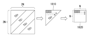
바람직하게, 상기 분할된 처리 블록이 2N×N/2인 경우, 절반의 수평 크기(half horizontal size)를 가지는 2개의 블록으로 분할되고, 상기 2개의 블록이 수직 방향으로 재배치됨으로써 N×N 정방형의 블록이 재구성될 수 있다. Preferably, when the divided processing block is 2N×N/2, it is divided into two blocks having a half horizontal size, and the two blocks are rearranged in a vertical direction to form an N×N square. Blocks can be reconstructed.
바람직하게, 상기 분할된 처리 블록이 N/2×2N인 경우, 절반의 수직 크기(half vertical size)를 가지는 2개의 블록으로 분할되고, 상기 2개의 블록을 수평 방향으로 재배치됨으로써 N×N 정방형의 블록이 재구성될 수 있다.Preferably, when the divided processing block is N/2×2N, it is divided into two blocks having a half vertical size, and the two blocks are rearranged in a horizontal direction to form an N×N square. Blocks can be reconstructed.
바람직하게, 상기 분할된 처리 블록에 포함된 샘플이 미리 정해진 순서에 따라 재배치됨으로써 정방형의 블록이 재구성될 수 있다. Preferably, the samples included in the divided processing blocks are rearranged in a predetermined order to reconstruct a square block.
바람직하게, 상기 분할된 처리 블록에 대한 참조 샘플을 구성하는 단계를 더 포함할 수 있다. Preferably, it may further include configuring a reference sample for the divided processing block.
바람직하게, 상기 분할된 처리 블록의 분할 방향이 수평 또는 수직 방향인 경우, 상기 참조 샘플은 상기 분할된 처리 블록의 좌측(left) 경계에 인접한 샘플, 상기 분할된 처리 블록의 상측(top) 경계에 인접한 샘플 및 상기 분할된 처리 블록의 좌상측(top-left)에 이웃하는 샘플로 구성될 수 있다. Preferably, when the division direction of the divided processing block is a horizontal or vertical direction, the reference sample is a sample adjacent to a left boundary of the divided processing block, and a top boundary of the divided processing block. It may be composed of adjacent samples and samples adjacent to the top-left side of the divided processing block.
바람직하게, 상기 처리 블록의 분할 방향이 45°인 경우, 상기 참조 샘플은 상기 분할된 처리 블록의 좌측(left) 경계에 인접한 샘플, 상기 분할된 처리 블록의 상측(top) 경계에 인접한 샘플 및 상기 분할된 처리 블록의 좌상측(top-left)에 이웃하는 샘플로 구성될 수 있다. Preferably, when the division direction of the processing block is 45°, the reference sample is a sample adjacent to a left boundary of the divided processing block, a sample adjacent to a top boundary of the divided processing block, and the It may be composed of samples adjacent to the top-left side of the divided processing block.
바람직하게, 상기 처리 블록의 분할 방향이 45°인 경우, 상기 참조 샘플은 상기 분할된 처리 블록의 좌상측(top-left) 경계에 인접한 샘플, 우측(right) 경계에 인접한 샘플 및 하측(bottom) 경계에 인접한 샘플로 구성될 수 있다. Preferably, when the division direction of the processing block is 45°, the reference sample is a sample adjacent to a top-left boundary of the divided processing block, a sample adjacent to a right boundary, and a bottom (bottom) It may consist of samples adjacent to the border.
본 발명의 실시예에 따르면, 정지 영상 또는 동영상을 인트라 예측 모드의 방향에 기반하여 분할함으로써, 인트라 예측 적용 시 참조 샘플과 예측 샘플과의 거리를 줄여 예측 정확도를 높일 수 있다. According to an embodiment of the present invention, by dividing a still image or a moving picture based on the direction of an intra prediction mode, when intra prediction is applied, a distance between a reference sample and a prediction sample may be reduced, thereby increasing prediction accuracy.
또한, 본 발명의 실시예에 따르면, 인트라 예측 모드의 방향에 기반하여 분할된 블록을 정방형 블록으로 재배치(또는 재구성)함으로써 기존에 정의된 변환/역변환 기법을 이용하여 변환/역변환을 수행할 수 있다. In addition, according to an embodiment of the present invention, transform/inverse transform may be performed using a previously defined transform/inverse transform technique by rearranging (or reconstructing) a divided block into a square block based on the direction of the intra prediction mode. .
본 발명에서 얻을 수 있는 효과는 이상에서 언급한 효과로 제한되지 않으며, 언급하지 않은 또 다른 효과들은 아래의 기재로부터 본 발명이 속하는 기술분야에서 통상의 지식을 가진 자에게 명확하게 이해될 수 있을 것이다.The effects obtained in the present invention are not limited to the above-mentioned effects, and other effects not mentioned will be clearly understood by those of ordinary skill in the art from the following description. .
본 발명에 관한 이해를 돕기 위해 상세한 설명의 일부로 포함되는, 첨부 도면은 본 발명에 대한 실시예를 제공하고, 상세한 설명과 함께 본 발명의 기술적 특징을 설명한다.
도 1은 본 발명이 적용되는 실시예로서, 정지 영상 또는 동영상 신호의 인코딩이 수행되는 인코더의 개략적인 블록도를 나타낸다.
도 2는 본 발명이 적용되는 실시예로서, 정지 영상 또는 동영상 신호의 인코딩이 수행되는 디코더의 개략적인 블록도를 나타낸다.
도 3은 본 발명에 적용될 수 있는 코딩 유닛의 분할 구조를 설명하기 위한 도면이다.
도 4는 본 발명에 적용될 수 있는 예측 유닛을 설명하기 위한 도면이다.
도 5는 본 발명이 적용되는 실시예로서, 인트라 예측 방법을 예시하는 도면이다.
도 6은 인트라 예측 모드에 따른 예측 방향을 예시한다.
도 7 및 도 8은 기존의 인트라 모드 예측에서의 문제점을 설명하기 위한 도면이다.
도 9는 본 발명의 일 실시예에 따른 인트라 예측 모드 기반 분할 방법을 예시한다.
도 10은 본 발명의 일 실시예에 따른 인트라 예측 모드 기반 분할된 블록에 대한 참조 샘플의 구성 방법을 예시한다.
도 11은 기존의 블록 분할 방식과 본 발명에 따른 인트라 예측 모드 기반 블록 분할 방식을 비교하여 설명하기 위한 도면이다.
도 12는 본 발명의 일 실시예에 따른 인트라 예측부를 보다 구체적으로 예시하는 도면이다.
도 13 및 도 14는 본 발명의 일 실시예에 따른 인트라 예측 모드 기반 영상 신호 처리 방법을 예시하는 도면이다.
도 15는 본 발명의 일 실시예에 따른 변환 유닛을 재배치(또는 재구성) 방법을 설명하기 위한 도면이다.
도 16은 기존의 변환 블록 분할 방식과 본 발명에 따른 변환 블록 재구성 방법을 비교하여 설명하기 위한 도면이다.
도 17은 본 발명의 일 실시예에 따른 변환 유닛의 재배치(또는 재구성) 방법을 설명하기 위한 도면이다.
도 18은 본 발명의 일 실시예에 따른 변환 유닛의 재배치(또는 재구성) 방법을 설명하기 위한 도면이다.
도 19는 본 발명의 일 실시예에 따른 변환부/역변환부를 보다 구체적으로 예시하는 도면이다.
도 20은 본 발명의 일 실시예에 따른 인트라 예측 모드 기반 영상 신호 처리 방법을 예시하는 도면이다.BRIEF DESCRIPTION OF THE DRAWINGS The accompanying drawings, which are included as part of the detailed description to aid in understanding of the present invention, provide embodiments of the present invention, and describe the technical features of the present invention together with the detailed description.
1 is a schematic block diagram of an encoder in which encoding of a still image or a moving image signal is performed as an embodiment to which the present invention is applied.
2 is a schematic block diagram of a decoder in which encoding of a still image or a moving image signal is performed as an embodiment to which the present invention is applied.
3 is a diagram for explaining a partitioning structure of a coding unit applicable to the present invention.
4 is a diagram for describing a prediction unit applicable to the present invention.
5 is a diagram illustrating an intra prediction method as an embodiment to which the present invention is applied.
6 illustrates a prediction direction according to an intra prediction mode.
7 and 8 are diagrams for explaining a problem in conventional intra mode prediction.
9 illustrates an intra prediction mode-based partitioning method according to an embodiment of the present invention.
10 illustrates a method of configuring a reference sample for a divided block based on an intra prediction mode according to an embodiment of the present invention.
11 is a diagram for describing a comparison between a conventional block partitioning method and an intra prediction mode-based block partitioning method according to the present invention.
12 is a diagram illustrating in more detail an intra prediction unit according to an embodiment of the present invention.
13 and 14 are diagrams illustrating an intra prediction mode-based video signal processing method according to an embodiment of the present invention.
15 is a diagram illustrating a method of rearranging (or reconfiguring) a transform unit according to an embodiment of the present invention.
16 is a diagram for describing a comparison between a conventional transform block division method and a transform block reconstruction method according to the present invention.
17 is a diagram for describing a method of rearranging (or reconfiguring) a transform unit according to an embodiment of the present invention.
18 is a diagram for describing a method of rearranging (or reconfiguring) a transform unit according to an embodiment of the present invention.
19 is a diagram illustrating in more detail a transform unit/inverse transform unit according to an embodiment of the present invention.
20 is a diagram illustrating a method of processing an image signal based on an intra prediction mode according to an embodiment of the present invention.
이하, 본 발명에 따른 바람직한 실시 형태를 첨부된 도면을 참조하여 상세하게 설명한다. 첨부된 도면과 함께 이하에 개시될 상세한 설명은 본 발명의 예시적인 실시형태를 설명하고자 하는 것이며, 본 발명이 실시될 수 있는 유일한 실시형태를 나타내고자 하는 것이 아니다. 이하의 상세한 설명은 본 발명의 완전한 이해를 제공하기 위해서 구체적 세부사항을 포함한다. 그러나, 당업자는 본 발명이 이러한 구체적 세부사항 없이도 실시될 수 있음을 안다. Hereinafter, preferred embodiments of the present invention will be described in detail with reference to the accompanying drawings. The detailed description to be disclosed hereinafter together with the accompanying drawings is intended to describe exemplary embodiments of the present invention, and is not intended to represent the only embodiments in which the present invention may be practiced. The following detailed description includes specific details to provide a thorough understanding of the present invention. However, one of ordinary skill in the art appreciates that the invention may be practiced without these specific details.
몇몇 경우, 본 발명의 개념이 모호해지는 것을 피하기 위하여 공지의 구조 및 장치는 생략되거나, 각 구조 및 장치의 핵심기능을 중심으로 한 블록도 형식으로 도시될 수 있다. In some cases, in order to avoid obscuring the concept of the present invention, well-known structures and devices may be omitted, or may be shown in a block diagram form centering on core functions of each structure and device.
아울러, 본 발명에서 사용되는 용어는 가능한 한 현재 널리 사용되는 일반적인 용어를 선택하였으나, 특정한 경우는 출원인이 임의로 선정한 용어를 사용하여 설명한다. 그러한 경우에는 해당 부분의 상세 설명에서 그 의미를 명확히 기재하므로, 본 발명의 설명에서 사용된 용어의 명칭만으로 단순 해석되어서는 안 될 것이며 그 해당 용어의 의미까지 파악하여 해석되어야 함을 밝혀두고자 한다.In addition, as for the terms used in the present invention, general terms that are currently widely used are selected as far as possible, but specific cases will be described using terms arbitrarily selected by the applicant. In such a case, since the meaning of the term is clearly described in the detailed description of the relevant part, it should not be interpreted simply by the name of the term used in the description of the present invention, and it should be clarified that the meaning of the term should be understood and interpreted. .
이하의 설명에서 사용되는 특정 용어들은 본 발명의 이해를 돕기 위해서 제공된 것이며, 이러한 특정 용어의 사용은 본 발명의 기술적 사상을 벗어나지 않는 범위에서 다른 형태로 변경될 수 있다. 예를 들어, 신호, 데이터, 샘플, 픽쳐, 프레임, 블록 등의 경우 각 코딩 과정에서 적절하게 대체되어 해석될 수 있을 것이다.Specific terms used in the following description are provided to aid understanding of the present invention, and the use of these specific terms may be changed in other forms without departing from the technical spirit of the present invention. For example, signals, data, samples, pictures, frames, blocks, etc. may be appropriately replaced and interpreted in each coding process.
이하 본 명세서에서 '처리 유닛'은 예측, 변환 및/또는 양자화 등과 같은 인코딩/디코딩의 처리 과정이 수행되는 단위를 의미한다. 이하, 설명의 편의를 위해 처리 유닛은 '처리 블록' 또는 '블록'으로 지칭될 수도 있다. Hereinafter, in the present specification, a'processing unit' refers to a unit in which an encoding/decoding process such as prediction, transformation, and/or quantization is performed. Hereinafter, for convenience of description, the processing unit may be referred to as a'processing block' or a'block'.
처리 유닛은 휘도(luma) 성분에 대한 단위와 색차(chroma) 성분에 대한 단위를 포함하는 의미로 해석될 수 있다. 예를 들어, 처리 유닛은 코딩 트리 유닛(CTU: Coding Tree Unit), 코딩 유닛(CU: Coding Unit), 예측 유닛(PU: Prediction Unit) 또는 변환 유닛(TU: Transform Unit)에 해당될 수 있다. The processing unit may be interpreted as including a unit for a luma component and a unit for a chroma component. For example, the processing unit may correspond to a coding tree unit (CTU), a coding unit (CU), a prediction unit (PU), or a transform unit (TU).
또한, 처리 유닛은 휘도(luma) 성분에 대한 단위 또는 색차(chroma) 성분에 대한 단위로 해석될 수 있다. 예를 들어, 처리 유닛은 휘도(luma) 성분에 대한 코딩 트리 블록(CTB: Coding Tree Block), 코딩 블록(CB: Coding Block), 예측 블록(PU: Prediction Block) 또는 변환 블록(TB: Transform Block)에 해당될 수 있다. 또는, 색차(chroma) 성분에 대한 코딩 트리 블록(CTB), 코딩 블록(CB), 예측 블록(PU) 또는 변환 블록(TB)에 해당될 수 있다. 또한, 이에 한정되는 것은 아니며 처리 유닛은 휘도(luma) 성분에 대한 단위와 색차(chroma) 성분에 대한 단위를 포함하는 의미로 해석될 수도 있다. Further, the processing unit may be interpreted as a unit for a luminance component or a unit for a chroma component. For example, the processing unit is a coding tree block (CTB: Coding Tree Block), a coding block (CB: Coding Block), a prediction block (PU: Prediction Block), or a transform block (TB) for a luminance component. ). Alternatively, it may correspond to a coding tree block (CTB), a coding block (CB), a prediction block (PU), or a transform block (TB) for a chroma component. In addition, the present invention is not limited thereto, and the processing unit may be interpreted as including a unit for a luminance component and a unit for a chroma component.
또한, 처리 유닛은 반드시 정사각형의 블록으로 한정되는 것은 아니며, 3개 이상의 꼭지점을 가지는 다각형 형태로 구성될 수도 있다. Further, the processing unit is not necessarily limited to a square block, and may be configured in a polygonal shape having three or more vertices.
또한, 이하 본 명세서에서 픽셀 또는 화소 등을 샘플로 통칭한다. 그리고, 샘플을 이용한다는 것은 픽셀 값 또는 화소 값 등을 이용한다는 것을 의미할 수 있다. In addition, in the present specification, pixels or pixels are collectively referred to as samples. And, using a sample may mean using a pixel value or a pixel value.
도 1은 본 발명이 적용되는 실시예로서, 정지 영상 또는 동영상 신호의 인코딩이 수행되는 인코더의 개략적인 블록도를 나타낸다.1 is a schematic block diagram of an encoder in which encoding of a still image or a moving image signal is performed as an embodiment to which the present invention is applied.
도 1을 참조하면, 인코더(100)는 영상 분할부(110), 감산기(115), 변환부(120), 양자화부(130), 역양자화부(140), 역변환부(150), 필터링부(160), 복호 픽쳐 버퍼(DPB: Decoded Picture Buffer)(170), 예측부(180) 및 엔트로피 인코딩부(190)를 포함하여 구성될 수 있다. 그리고, 예측부(180)는 인터 예측부(181), 인트라 예측부(182)을 포함하여 구성될 수 있다. Referring to FIG. 1, the encoder 100 includes an
영상 분할부(110)는 인코더(100)에 입력된 입력 영상 신호(Input video signal)(또는, 픽쳐, 프레임)를 하나 이상의 처리 유닛으로 분할한다. The
감산기(115)는 입력 영상 신호에서 예측부(180)로부터(즉, 인터 예측부(181) 또는 인트라 예측부(182))로부터 출력된 예측 신호(prediction signal)(또는 예측 블록)를 감산하여 차분 신호(residual signal)(또는 차분 블록)를 생성한다. 생성된 차분 신호(또는 차분 블록)는 변환부(120)로 전송된다. The
변환부(120)는 차분 신호(또는 차분 블록)에 변환 기법(예를 들어, DCT(Discrete Cosine Transform), DST(Discrete Sine Transform), GBT(Graph-Based Transform), KLT(Karhunen-Loeve transform) 등)을 적용하여 변환 계수(transform coefficient)를 생성한다. 이때, 변환부(120)는 차분 블록에 적용된 예측 모드와 차분 블록의 크기에 따라서 결정된 변환 기법을 이용하여 변환을 수행함으로써 변환 계수들을 생성할 수 있다. The
특히, 본 발명에 따른 변환부(120)는 현재 처리 블록이 정방형 블록이 아닌 경우, 처리 블록을 정방형의 블록으로 재구성하여 변환을 수행할 수 있다. 변환부(120)에 대한 보다 상세한 설명은 후술한다. In particular, when the current processing block is not a square block, the
양자화부(130)는 변환 계수를 양자화하여 엔트로피 인코딩부(190)로 전송하고, 엔트로피 인코딩부(190)는 양자화된 신호(quantized signal)를 엔트로피 코딩하여 비트 스트림으로 출력한다.The
한편, 양자화부(130)로부터 출력된 양자화된 신호(quantized signal)는 예측 신호를 생성하기 위해 이용될 수 있다. 예를 들어, 양자화된 신호(quantized signal)는 루프 내의 역양자화부(140) 및 역변환부(150)를 통해 역양자화 및 역변환을 적용함으로써 차분 신호를 복원할 수 있다. 복원된 차분 신호를 인터 예측부(181) 또는 인트라 예측부(182)로부터 출력된 예측 신호(prediction signal)에 더함으로써 복원 신호(reconstructed signal)가 생성될 수 있다. Meanwhile, a quantized signal output from the
한편, 위와 같은 압축 과정에서 인접한 블록들이 서로 다른 양자화 파라미터에 의해 양자화됨으로써 블록 경계가 보이는 열화가 발생될 수 있다. 이러한 현상을 블록킹 열화(blocking artifacts)라고 하며, 이는 화질을 평가하는 중요한 요소 중의 하나이다. 이러한 열화를 줄이기 위해 필터링 과정을 수행할 수 있다. 이러한 필터링 과정을 통해 블록킹 열화를 제거함과 동시에 현재 픽쳐에 대한 오차를 줄임으로써 화질을 향상시킬 수 있게 된다.Meanwhile, in the above compression process, adjacent blocks are quantized by different quantization parameters, so that block boundaries can be seen deterioration. This phenomenon is called blocking artifacts, which is one of the important factors in evaluating image quality. To reduce such deterioration, a filtering process may be performed. Through this filtering process, blocking deterioration can be removed and an error for a current picture can be reduced, thereby improving image quality.
필터링부(160)는 복원 신호에 필터링을 적용하여 이를 재생 장치로 출력하거나 복호 픽쳐 버퍼(170)에 전송한다. 복호 픽쳐 버퍼(170)에 전송된 필터링된 신호는 인터 예측부(181)에서 참조 픽쳐로 사용될 수 있다. 이처럼, 필터링된 픽쳐를 화면간 예측 모드에서 참조 픽쳐로 이용함으로써 화질 뿐만 아니라 부호화 효율도 향상시킬 수 있다. The filtering unit 160 applies filtering to the reconstructed signal and outputs the filtering to the reproduction device or transmits it to the decoded
복호 픽쳐 버퍼(170)는 필터링된 픽쳐를 인터 예측부(181)에서의 참조 픽쳐으로 사용하기 위해 저장할 수 있다.The decoded
인터 예측부(181)는 복원 픽쳐(reconstructed picture)를 참조하여 시간적 중복성 및/또는 공간적 중복성을 제거하기 위해 시간적 예측 및/또는 공간적 예측을 수행한다. 여기서, 예측을 수행하기 위해 이용되는 참조 픽쳐는 이전 시간에 부호화/복호화 시 블록 단위로 양자화와 역양자화를 거친 변환된 신호이기 때문에, 블로킹 아티팩트(blocking artifact)나 링잉 아티팩트(ringing artifact)가 존재할 수 있다. The
따라서, 인터 예측부(181)는 이러한 신호의 불연속이나 양자화로 인한 성능 저하를 해결하기 위해, 로우패스 필터(lowpass filter)를 적용함으로써 픽셀들 사이의 신호를 서브 픽셀 단위로 보간할 수 있다. 여기서, 서브 픽셀은 보간 필터를 적용하여 생성된 가상의 화소를 의미하고, 정수 픽셀은 복원된 픽쳐에 존재하는 실제 화소를 의미한다. 보간 방법으로는 선형 보간, 양선형 보간(bi-linear interpolation), 위너 필터(wiener filter) 등이 적용될 수 있다.Accordingly, the
보간 필터는 복원 픽쳐(reconstructed picture)에 적용되어 예측의 정밀도를 향상시킬 수 있다. 예를 들어, 인터 예측부(181)는 정수 픽셀에 보간 필터를 적용하여 보간 픽셀을 생성하고, 보간 픽셀들(interpolated pixels)로 구성된 보간 블록(interpolated block)을 예측 블록(prediction block)으로 사용하여 예측을 수행할 수 있다. The interpolation filter may be applied to a reconstructed picture to improve the precision of prediction. For example, the
인트라 예측부(182)는 현재 부호화를 진행하려고 하는 블록의 주변에 있는 샘플들을 참조하여 현재 블록을 예측한다. 인트라 예측부(182)는, 인트라 예측을 수행하기 위해 다음과 같은 과정을 수행할 수 있다. 먼저, 예측 신호를 생성하기 위해 필요한 참조 샘플을 준비할 수 있다. 그리고, 준비된 참조 샘플을 이용하여 예측 신호를 생성할 수 있다. 이후, 예측 모드를 부호화하게 된다. 이때, 참조 샘플은 참조 샘플 패딩 및/또는 참조 샘플 필터링을 통해 준비될 수 있다. 참조 샘플은 예측 및 복원 과정을 거쳤기 때문에 양자화 에러가 존재할 수 있다. 따라서, 이러한 에러를 줄이기 위해 인트라 예측에 이용되는 각 예측 모드에 대해 참조 샘플 필터링 과정이 수행될 수 있다.The
특히, 본 발명에 따른 인트라 예측부(182)는 현재 처리 블록을 인트라 예측 모드에 기반하여 결정된 분할 방향에 따라 처리 블록을 분할하고, 분할된 처리 블록에 대하여 인트라 예측을 수행할 수 있다. 인트라 예측부(182)에 대한 보다 상세한 설명은 후술한다.In particular, the
인터 예측부(181) 또는 상기 인트라 예측부(182)를 통해 생성된 예측 신호(prediction signal)(또는 예측 블록)는 복원 신호(또는 복원 블록)를 생성하기 위해 이용되거나 차분 신호(또는 차분 블록)를 생성하기 위해 이용될 수 있다. The prediction signal (or prediction block) generated by the
도 2는 본 발명이 적용되는 실시예로서, 정지 영상 또는 동영상 신호의 인코딩이 수행되는 디코더의 개략적인 블록도를 나타낸다.2 is a schematic block diagram of a decoder in which encoding of a still image or a moving image signal is performed as an embodiment to which the present invention is applied.
도 2를 참조하면, 디코더(200)는 엔트로피 디코딩부(210), 역양자화부(220), 역변환부(230), 가산기(235), 필터링부(240), 복호 픽쳐 버퍼(DPB: Decoded Picture Buffer Unit)(250), 예측부(260)를 포함하여 구성될 수 있다. 그리고, 예측부(260)는 인터 예측부(261) 및 인트라 예측부(262)를 포함하여 구성될 수 있다. Referring to FIG. 2, the decoder 200 includes an
그리고, 디코더(200)를 통해 출력된 복원 영상 신호(reconstructed video signal)는 재생 장치를 통해 재생될 수 있다.In addition, a reconstructed video signal output through the decoder 200 may be reproduced through a playback device.
디코더(200)는 도 1의 인코더(100)로부터 출력된 신호(즉, 비트 스트림)을 수신하고, 수신된 신호는 엔트로피 디코딩부(210)를 통해 엔트로피 디코딩된다. The decoder 200 receives a signal (ie, a bit stream) output from the encoder 100 of FIG. 1, and the received signal is entropy decoded through the
역양자화부(220)에서는 양자화 스텝 사이즈 정보를 이용하여 엔트로피 디코딩된 신호로부터 변환 계수(transform coefficient)를 획득한다. The
역변환부(230)에서는 역변환 기법을 적용하여 변환 계수를 역변환하여 차분 신호(residual signal)(또는 차분 블록)를 획득하게 된다. The
특히, 본 발명에 따른 역변환부(230)는 현재 처리 블록이 정방형 블록이 아닌 경우, 처리 블록을 정방형의 블록으로 재구성하여 역변환을 수행할 수 있다. 역변환부(230)에 대한 보다 상세한 설명은 후술한다. In particular, when the current processing block is not a square block, the
가산기(235)는 획득된 차분 신호(또는 차분 블록)를 예측부(260)(즉, 인터 예측부(261) 또는 인트라 예측부(262))로부터 출력된 예측 신호(prediction signal)(또는 예측 블록)에 더함으로써 복원 신호(reconstructed signal)(또는 복원 블록)가 생성된다.The
필터링부(240)는 복원 신호(reconstructed signal)(또는 복원 블록)에 필터링을 적용하여 이를 재생 장치로 출력하거나 복호 픽쳐 버퍼부(250)에 전송한다. 복호 픽쳐 버퍼부(250)에 전송된 필터링된 신호는 인터 예측부(261)에서 참조 픽쳐로 사용될 수 있다. The
본 명세서에서, 인코더(100)의 필터링부(160), 인터 예측부(181) 및 인트라 예측부(182)에서 설명된 실시예들은 각각 디코더의 필터링부(240), 인터 예측부(261) 및 인트라 예측부(262)에도 동일하게 적용될 수 있다.In this specification, the embodiments described in the filtering unit 160, the
특히, 본 발명에 따른 인트라 예측부(262)는 현재 처리 블록을 인트라 예측 모드에 기반하여 결정된 분할 방향에 따라 처리 블록을 분할하고, 분할된 처리 블록에 대하여 인트라 예측을 수행할 수 있다. 인트라 예측부(262)에 대한 보다 상세한 설명은 후술한다.In particular, the
일반적으로 정지 영상 또는 동영상 압축 기술(예를 들어, HEVC)에서는 블록 기반의 영상 압축 방법을 이용한다. 블록 기반의 영상 압축 방법은 영상을 특정 블록 단위로 나누어서 처리하는 방법으로서, 메모리 사용과 연산량을 감소시킬 수 있다. In general, a still image or moving image compression technique (eg, HEVC) uses a block-based image compression method. The block-based image compression method is a method of dividing an image into a specific block and processing it, and can reduce memory usage and computational amount.
도 3은 본 발명에 적용될 수 있는 코딩 유닛의 분할 구조를 설명하기 위한 도면이다.3 is a diagram for explaining a partitioning structure of a coding unit applicable to the present invention.
인코더는 하나의 영상(또는 픽쳐)을 사각형 형태의 코딩 트리 유닛(CTU: Coding Tree Unit) 단위로 분할한다. 그리고, 래스터 스캔 순서(raster scan order)에 따라 하나의 CTU 씩 순차적으로 인코딩한다.The encoder divides one image (or picture) into a rectangular coding tree unit (CTU) unit. In addition, one CTU is sequentially encoded according to a raster scan order.
HEVC에서 CTU의 크기는 64×64, 32×32, 16×16 중 어느 하나로 정해질 수 있다. 인코더는 입력된 영상의 해상도 또는 입력된 영상의 특성 등에 따라 CTU의 크기를 선택하여 사용할 수 있다. CTU은 휘도(luma) 성분에 대한 코딩 트리 블록(CTB: Coding Tree Block)과 이에 대응하는 두 개의 색차(chroma) 성분에 대한 CTB를 포함한다.In HEVC, the size of the CTU may be set to one of 64×64, 32×32, and 16×16. The encoder can select and use the size of the CTU according to the resolution of the input video or the characteristics of the input video. The CTU includes a coding tree block (CTB) for a luminance component and a CTB for two corresponding chroma components.
하나의 CTU은 쿼드-트리(Quad-tree) 구조로 분할될 수 있다. 즉, 하나의 CTU은 정사각형 형태를 가지면서 절반의 수평 크기(half horizontal size) 및 절반의 수직 크기(half vertical size)를 가지는 4개의 유닛으로 분할되어 코딩 유닛(CU: Coding Unit)이 생성될 수 있다. 이러한 쿼드-트리 구조의 분할은 재귀적으로 수행될 수 있다. 즉, CU은 하나의 CTU로부터 쿼드-트리 구조로 계층적으로 분할된다.One CTU may be divided into a quad-tree structure. That is, one CTU is divided into four units having a square shape and having a half horizontal size and a half vertical size to generate a coding unit (CU). have. The division of the quad-tree structure can be performed recursively. That is, the CU is hierarchically partitioned from one CTU into a quad-tree structure.
CU은 입력 영상의 처리 과정, 예컨대 인트라(intra)/인터(inter) 예측이 수행되는 코딩의 기본 단위를 의미한다. CU은 휘도(luma) 성분에 대한 코딩 블록(CB: Coding Block)과 이에 대응하는 두 개의 색차(chroma) 성분에 대한 CB를 포함한다. HEVC에서 CU의 크기는 64×64, 32×32, 16×16, 8×8 중 어느 하나로 정해질 수 있다. CU refers to a basic unit of coding in which an input image is processed, for example, intra/inter prediction is performed. The CU includes a coding block (CB) for a luminance component and a CB for two chroma components corresponding thereto. In HEVC, the size of the CU may be set to one of 64×64, 32×32, 16×16, and 8×8.
도 3을 참조하면, 쿼드-트리의 루트 노드(root node)는 CTU와 관련된다. 쿼드-트리는 리프 노드(leaf node)에 도달할 때까지 분할되고, 리프 노드는 CU에 해당한다. Referring to FIG. 3, a root node of a quad-tree is related to a CTU. The quad-tree is divided until it reaches a leaf node, and the leaf node corresponds to a CU.
보다 구체적으로 살펴보면, CTU는 루트 노드(root node)에 해당되고, 가장 작은 깊이(depth)(즉, depth=0) 값을 가진다. 입력 영상의 특성에 따라 CTU가 분할되지 않을 수도 있으며, 이 경우 CTU은 CU에 해당한다. More specifically, the CTU corresponds to a root node and has the smallest depth (ie, depth=0) value. The CTU may not be divided according to the characteristics of the input image, and in this case, the CTU corresponds to the CU.
CTU은 쿼드 트리 형태로 분할될 수 있으며, 그 결과 깊이 1(depth=1)인 하위 노드들이 생성된다. 그리고, 1의 깊이를 가지는 하위 노드에서 더 이상 분할되지 않은 노드(즉, 리프 노드)는 CU에 해당한다. 예를 들어, 도 3(b)에서 노드 a, b 및 j에 대응하는 CU(a), CU(b), CU(j)는 CTU에서 한 번 분할되었으며, 1의 깊이를 가진다.The CTU can be divided into a quad tree shape, and as a result, lower nodes with a depth of 1 (depth = 1) are generated. In addition, a node (ie, a leaf node) that is no longer divided in a lower node having a depth of 1 corresponds to a CU. For example, in FIG. 3(b), CU(a), CU(b), and CU(j) corresponding to nodes a, b, and j are divided once in the CTU and have a depth of 1.
1의 깊이를 가지는 노드 중 적어도 어느 하나는 다시 퀴드 트리 형태로 분할될 수 있으며, 그 결과 깊이 1(즉, depth=2)인 하위 노드들이 생성된다. 그리고, 2의 깊이를 가지는 하위 노드에서 더 이상 분할되지 않은 노드(즉, 리프 노드)는 CU에 해당한다. 예를 들어, 도 3(b)에서 노드 c, h 및 i에 대응하는 CU(c), CU(h), CU(i)는 CTU에서 두 번 분할되었으며, 2의 깊이를 가진다. At least one of the nodes having a depth of 1 may be divided into a quid tree shape again, and as a result, sub-nodes having a depth of 1 (ie, depth=2) are generated. In addition, a node (ie, a leaf node) that is no longer divided in a lower node having a depth of 2 corresponds to a CU. For example, in FIG. 3(b), CU(c), CU(h), and CU(i) corresponding to nodes c, h, and i are divided twice in the CTU and have a depth of 2.
또한, 2의 깊이를 가지는 노드 중 적어도 어느 하나는 다시 쿼드 트리 형태로 분할될 수 있으며, 그 결과 깊이 3(즉, depth=3)인 하위 노드들이 생성된다. 그리고, 3의 깊이를 가지는 하위 노드에서 더 이상 분할되지 않은 노드(즉, 리프 노드)는 CU에 해당한다. 예를 들어, 도 3(b)에서 노드 d, e, f, g에 대응하는 CU(d), CU(e), CU(f), CU(g)는 CTU에서 3번 분할되었으며, 3의 깊이를 가진다.In addition, at least one of the nodes having a depth of 2 may be divided into a quad tree shape again, and as a result, lower nodes having a depth of 3 (ie, depth = 3) are generated. In addition, a node (ie, a leaf node) that is no longer divided in a lower node having a depth of 3 corresponds to a CU. For example, in FIG. 3(b), CU(d), CU(e), CU(f), and CU(g) corresponding to nodes d, e, f, and g were divided 3 times in CTU, and Have depth.
인코더에서는 비디오 영상의 특성(예를 들어, 해상도)에 따라서 혹은 부호화의 효율을 고려하여 CU의 최대 크기 또는 최소 크기를 결정할 수 있다. 그리고, 이에 대한 정보 또는 이를 유도할 수 있는 정보가 비트스트림에 포함될 수 있다. 최대 크기를 가지는 CU를 최대 코딩 유닛(LCU: Largest Coding Unit)이라고 지칭하며, 최소 크기를 가지는 CU를 최소 코딩 유닛(SCU: Smallest Coding Unit)이라고 지칭할 수 있다. The encoder may determine the maximum size or the minimum size of the CU according to the characteristics (eg, resolution) of the video image or in consideration of encoding efficiency. In addition, information about this or information for inducing it may be included in the bitstream. A CU having a maximum size may be referred to as a largest coding unit (LCU), and a CU having a minimum size may be referred to as a smallest coding unit (SCU).
또한, 트리 구조를 갖는 CU은 미리 정해진 최대 깊이 정보(또는, 최대 레벨 정보)를 가지고 계층적으로 분할될 수 있다. 그리고, 각각의 분할된 CU은 깊이 정보를 가질 수 있다. 깊이 정보는 CU의 분할된 횟수 및/또는 정도를 나타내므로, CU의 크기에 관한 정보를 포함할 수도 있다.Also, a CU having a tree structure may be hierarchically divided with predetermined maximum depth information (or maximum level information). And, each divided CU may have depth information. Since the depth information indicates the number and/or degree of division of the CU, it may include information about the size of the CU.
LCU가 쿼드 트리 형태로 분할되므로, LCU의 크기 및 최대 깊이 정보를 이용하면 SCU의 크기를 구할 수 있다. 또는 역으로, SCU의 크기 및 트리의 최대 깊이 정보를 이용하면, LCU의 크기를 구할 수 있다.Since the LCU is divided into a quad tree, the size of the SCU can be obtained using information on the size and maximum depth of the LCU. Or, conversely, by using information on the size of the SCU and the maximum depth of the tree, the size of the LCU can be obtained.
하나의 CU에 대하여, 해당 CU이 분할 되는지 여부를 나타내는 정보(예를 들어, 분할 CU 플래그(split_cu_flag))가 디코더에 전달될 수 있다. 이 분할 정보는 SCU을 제외한 모든 CU에 포함되어 있다. 예를 들어, 분할 여부를 나타내는 플래그의 값이 '1'이면 해당 CU은 다시 4개의 CU으로 나누어지고, 분할 여부를 나타내는 플래그의 값이 '0'이면 해당 CU은 더 이상 나누어지지 않고 해당 CU에 대한 처리 과정이 수행될 수 있다.For one CU, information indicating whether the corresponding CU is divided (eg, a split CU flag (split_cu_flag)) may be delivered to the decoder. This partitioning information is included in all CUs except SCU. For example, if the value of the flag indicating whether to be divided is '1', the CU is divided into 4 CUs, and if the value of the flag indicating whether to be divided is '0', the CU is no longer divided and The treatment process for can be performed.
상술한 바와 같이, CU는 인트라 예측 또는 인터 예측이 수행되는 코딩의 기본 단위이다. HEVC는 입력 영상을 보다 효과적으로 코딩하기 위하여 CU를 예측 유닛(PU: Prediction Unit) 단위로 분할한다. As described above, the CU is a basic unit of coding in which intra prediction or inter prediction is performed. HEVC divides a CU into prediction units (PUs) in order to more effectively code an input image.
PU는 예측 블록을 생성하는 기본 단위로서, 하나의 CU 내에서도 PU 단위로 서로 다르게 예측 블록을 생성할 수 있다. 다만, 하나의 CU 내에 속한 PU들은 인트라 예측과 인터 예측이 혼합되어 사용되지 않으며, 하나의 CU 내에 속한 PU들은 동일한 예측 방법(즉, 인트라 예측 혹은 인터 예측)으로 코딩된다.A PU is a basic unit for generating a prediction block, and a prediction block may be differently generated in a PU unit even in one CU. However, PUs belonging to one CU are not used by mixing intra prediction and inter prediction, and PUs belonging to one CU are coded using the same prediction method (ie, intra prediction or inter prediction).
PU는 쿼드-트리 구조로 분할되지 않으며, 하나의 CU에서 미리 정해진 형태로 한번 분할된다. 이에 대하여 아래 도면을 참조하여 설명한다.The PU is not divided into a quad-tree structure, and is divided once in a predetermined form in one CU. This will be described with reference to the drawings below.
도 4는 본 발명에 적용될 수 있는 예측 유닛을 설명하기 위한 도면이다. 4 is a diagram for describing a prediction unit applicable to the present invention.
PU는 PU가 속하는 CU의 코딩 모드로 인트라 예측 모드가 사용되는지 인터 예측 모드가 사용되는지에 따라 상이하게 분할된다.The PU is divided differently depending on whether an intra prediction mode or an inter prediction mode is used as a coding mode of a CU to which the PU belongs.
도 4(a)는 인트라 예측 모드가 사용되는 경우의 PU를 예시하고, 도 4(b)는 인터 예측 모드가 사용되는 경우의 PU를 예시한다. FIG. 4(a) illustrates a PU when an intra prediction mode is used, and FIG. 4(b) illustrates a PU when an inter prediction mode is used.
도 4(a)를 참조하면, 하나의 CU의 크기가 2N×2N(N=4,8,16,32)인 경우를 가정하면, 하나의 CU는 2가지 타입(즉, 2N×2N 또는 N×N)으로 분할될 수 있다. Referring to FIG. 4(a), assuming that the size of one CU is 2N×2N (N=4,8,16,32), one CU has two types (that is, 2N×2N or N It can be divided by ×N).
여기서, 2N×2N 형태의 PU로 분할되는 경우, 하나의 CU 내에 하나의 PU만이 존재하는 것을 의미한다. Here, when it is divided into a 2N×2N type PU, it means that only one PU exists in one CU.
반면, N×N 형태의 PU로 분할되는 경우, 하나의 CU는 4개의 PU로 분할되고, 각 PU 단위 별로 서로 다른 예측 블록이 생성된다. 다만, 이러한 PU의 분할은 CU의 휘도 성분에 대한 CB의 크기가 최소 크기인 경우(즉, CU가 SCU인 경우)에만 수행될 수 있다. On the other hand, when divided into N×N type PUs, one CU is divided into 4 PUs, and different prediction blocks are generated for each PU unit. However, this division of the PU can be performed only when the size of the CB for the luminance component of the CU is the minimum size (that is, when the CU is an SCU).
도 4(b)를 참조하면, 하나의 CU의 크기가 2N×2N(N=4,8,16,32)인 경우를 가정하면, 하나의 CU는 8가지의 PU 타입(즉, 2N×2N, N×N, 2N×N, N×2N, nL×2N, nR×2N, 2N×nU, 2N×nD)으로 분할될 수 있다.Referring to FIG. 4(b), assuming that the size of one CU is 2N×2N (N=4,8,16,32), one CU has eight PU types (i.e., 2N×2N). , N×N, 2N×N, N×2N, nL×2N,
인트라 예측과 유사하게, N×N 형태의 PU 분할은 CU의 휘도 성분에 대한 CB의 크기가 최소 크기인 경우(즉, CU가 SCU인 경우)에만 수행될 수 있다. Similar to intra prediction, the N×N type of PU partitioning can be performed only when the size of the CB for the luminance component of the CU is the minimum size (ie, the CU is the SCU).
인터 예측에서는 가로 방향으로 분할되는 2N×N 형태 및 세로 방향으로 분할되는 N×2N 형태의 PU 분할을 지원한다. In the inter prediction, a 2N×N type divided in a horizontal direction and an N×2N type PU divided in a vertical direction are supported.
또한, 비대칭 움직임 분할(AMP: Asymmetric Motion Partition) 형태인 nL×2N, nR×2N, 2N×nU, 2N×nD 형태의 PU 분할을 지원한다. 여기서, 'n'은 2N의 1/4 값을 의미한다. 다만, AMP는 PU가 속한 CU가 최소 크기의 CU인 경우 사용될 수 없다. In addition, PU partitioning in nL×2N,
하나의 CTU 내의 입력 영상을 효율적으로 부호화하기 위해 코딩 유닛(CU), 예측 유닛(PU), 변환 유닛(TU)의 최적의 분할 구조는 아래와 같은 수행 과정을 거쳐 최소 율-왜곡(Rate-Distortion) 값을 기반으로 결정될 수 있다. 예를 들어, 64×64 CTU 내 최적의 CU 분할 과정을 살펴보면, 64×64 크기의 CU에서 8×8 크기의 CU까지의 분할 과정을 거치면서 율-왜곡 비용을 계산할 수 있다. 구체적인 과정은 다음과 같다.In order to efficiently encode the input image within one CTU, the optimal partition structure of the coding unit (CU), prediction unit (PU), and transform unit (TU) is performed through the following process to achieve minimum rate-distortion. It can be determined based on the value. For example, looking at the optimal CU partitioning process in a 64×64 CTU, the rate-distortion cost can be calculated by going through the partitioning process from a 64×64 CU to an 8×8 CU. The specific process is as follows.
1) 64×64 크기의 CU에 대해 인터/인트라 예측, 변환/양자화, 역양자화/역변환 및 엔트로피 인코딩 수행을 통해 최소의 율-왜곡 값을 발생시키는 최적의 PU와 TU의 분할 구조를 결정한다.1) For a CU of 64×64 size, the optimal partition structure of the PU and TU that generates the minimum rate-distortion value is determined by performing inter/intra prediction, transform/quantization, inverse quantization/inverse transform and entropy encoding.
2) 64×64 CU를 32×32 크기의 CU 4개로 분할하고 각 32×32 CU에 대해 최소의 율-왜곡 값을 발생시키는 최적의 PU와 TU의 분할 구조를 결정한다.2) The 64×64 CU is divided into 4 CUs of 32×32 size, and the optimal partitioning structure of the PU and TU that generates the minimum rate-distortion value for each 32×32 CU is determined.
3) 32×32 CU를 16×16 크기의 CU 4개로 다시 분할하고, 각 16×16 CU에 대해 최소의 율-왜곡 값을 발생시키는 최적의 PU와 TU의 분할 구조를 결정한다.3) The 32×32 CU is divided into 4 CUs of 16×16 size, and the optimal partitioning structure of the PU and TU that generates the minimum rate-distortion value for each 16×16 CU is determined.
4) 16×16 CU를 8×8 크기의 CU 4개로 다시 분할하고, 각 8×8 CU에 대해 최소의 율-왜곡 값을 발생시키는 최적의 PU와 TU의 분할 구조를 결정한다.4) The 16×16 CU is divided into 4 CUs of 8×8 size, and an optimal partitioning structure of the PU and TU that generates the minimum rate-distortion value for each 8×8 CU is determined.
5) 위의 3)의 과정에서 산출한 16×16 CU의 율-왜곡 값과 위의 4)의 과정에서 산출한 4개 8×8 CU의 율-왜곡 값의 합을 비교하여 16×16 블록 내에서 최적의 CU의 분할 구조를 결정한다. 이 과정을 나머지 3개의 16×16 CU들에 대해서도 동일하게 수행한다.5) 16×16 blocks by comparing the rate-distortion values of the 16×16 CUs calculated in the process of 3) above and the rate-distortion values of the four 8×8 CUs calculated in the process of 4) above. Determine the optimal CU partition structure within This process is also performed for the remaining 3 16×16 CUs.
6) 위의 2)의 과정에서 계산된 32×32 CU의 율-왜곡 값과 위의 5)의 과정에서 획득한 4개 16×16 CU의 율-왜곡 값의 합을 비교하여 32×32 블록 내에서 최적의 CU의 분할 구조를 결정한다. 이 과정을 나머지 3개의 32×32 CU들에 대해서도 동일하게 수행한다.6) A 32×32 block by comparing the rate-distortion value of the 32×32 CU calculated in the process of 2) above and the rate-distortion value of the four 16×16 CUs obtained in the process of 5) above. Determine the optimal CU partition structure within The same process is performed for the remaining 3 32×32 CUs.
7) 마지막으로, 위의 1)의 과정에서 계산된 64×64 CU의 율-왜곡 값과 위의 6)의 과정에서 획득한 4개 32×32 CU의 율-왜곡 값의 합을 비교하여 64×64 블록 내에서 최적의 CU의 분할 구조를 결정한다.7) Finally, compare the rate-distortion values of 64×64 CUs calculated in the process of 1) above and the rate-distortion values of 4 32×32 CUs obtained in the process of 6) above. Determine the optimal CU partition structure within x64 blocks.
인트라 예측 모드에서, PU 단위로 예측 모드가 선택되고, 선택된 예측 모드에 대해 실제 TU 단위로 예측과 재구성이 수행된다.In the intra prediction mode, a prediction mode is selected on a PU basis, and prediction and reconstruction are performed on an actual TU basis on the selected prediction mode.
TU는 실제 예측과 재구성이 수행되는 기본 단위를 의미한다. TU는 휘도(luma) 성분에 대한 변환 블록(TB: Transform Block)과 이에 대응하는 두 개의 색차(chroma) 성분에 대한 TB를 포함한다. TU means a basic unit in which actual prediction and reconstruction are performed. The TU includes a transform block (TB) for a luma component and a TB for two corresponding chroma components.
앞서 도 3의 예시에서 하나의 CTU가 쿼드-트리 구조로 분할되어 CU가 생성되는 것과 같이, TU는 코딩하려는 하나의 CU로부터 쿼드-트리 구조로 계층적으로 분할된다. As in the example of FIG. 3 above, as one CTU is divided into a quad-tree structure to generate a CU, the TU is hierarchically divided from one CU to be coded into a quad-tree structure.
TU는 쿼드-트리 구조로 분할되므로 CU로부터 분할된 TU는 다시 더 작은 하위 TU로 분할될 수 있다. HEVC에서는 TU의 크기는 32×32, 16×16, 8×8, 4×4 중 어느 하나로 정해질 수 있다.Since the TU is divided into a quad-tree structure, the TU divided from the CU can be divided into smaller lower TUs. In HEVC, the size of the TU may be set to any one of 32×32, 16×16, 8×8, and 4×4.
다시 도 3을 참조하면, 쿼드-트리의 루트 노드(root node)는 CU와 관련된다고 가정한다. 쿼드-트리는 리프 노드(leaf node)에 도달할 때까지 분할되고, 리프 노드는 TU에 해당한다. Referring back to FIG. 3, it is assumed that the root node of the quad-tree is related to the CU. The quad-tree is divided until it reaches a leaf node, and the leaf node corresponds to the TU.
보다 구체적으로 살펴보면, CU는 루트 노드(root node)에 해당되고, 가장 작은 깊이(depth)(즉, depth=0) 값을 가진다. 입력 영상의 특성에 따라 CU가 분할되지 않을 수도 있으며, 이 경우 CU은 TU에 해당한다. More specifically, the CU corresponds to a root node and has the smallest depth (ie, depth=0) value. The CU may not be divided according to the characteristics of the input image, and in this case, the CU corresponds to the TU.
CU은 쿼드 트리 형태로 분할될 수 있으며, 그 결과 깊이 1(depth=1)인 하위 노드들이 생성된다. 그리고, 1의 깊이를 가지는 하위 노드에서 더 이상 분할되지 않은 노드(즉, 리프 노드)는 TU에 해당한다. 예를 들어, 도 3(b)에서 노드 a, b 및 j에 대응하는 TU(a), TU(b), TU(j)는 CU에서 한 번 분할되었으며, 1의 깊이를 가진다.The CU can be divided into a quad tree shape, and as a result, lower nodes with a depth of 1 (depth=1) are generated. In addition, a node (ie, a leaf node) that is no longer divided in a lower node having a depth of 1 corresponds to a TU. For example, in FIG. 3(b), TU(a), TU(b), and TU(j) corresponding to nodes a, b, and j are divided once in the CU and have a depth of 1.
1의 깊이를 가지는 노드 중 적어도 어느 하나는 다시 퀴드 트리 형태로 분할될 수 있으며, 그 결과 깊이 1(즉, depth=2)인 하위 노드들이 생성된다. 그리고, 2의 깊이를 가지는 하위 노드에서 더 이상 분할되지 않은 노드(즉, 리프 노드)는 TU에 해당한다. 예를 들어, 도 3(b)에서 노드 c, h 및 i에 대응하는 TU(c), TU(h), TU(i)는 CU에서 두 번 분할되었으며, 2의 깊이를 가진다. At least one of the nodes having a depth of 1 may be divided into a quid tree shape again, and as a result, sub-nodes having a depth of 1 (ie, depth=2) are generated. In addition, a node (ie, a leaf node) that is no longer divided in a lower node having a depth of 2 corresponds to a TU. For example, TU(c), TU(h), and TU(i) corresponding to nodes c, h, and i in FIG. 3(b) are divided twice in the CU, and have a depth of 2.
또한, 2의 깊이를 가지는 노드 중 적어도 어느 하나는 다시 쿼드 트리 형태로 분할될 수 있으며, 그 결과 깊이 3(즉, depth=3)인 하위 노드들이 생성된다. 그리고, 3의 깊이를 가지는 하위 노드에서 더 이상 분할되지 않은 노드(즉, 리프 노드)는 CU에 해당한다. 예를 들어, 도 3(b)에서 노드 d, e, f, g에 대응하는 TU(d), TU(e), TU(f), TU(g)는 CU에서 3번 분할되었으며, 3의 깊이를 가진다.In addition, at least one of the nodes having a depth of 2 may be divided into a quad tree shape again, and as a result, lower nodes having a depth of 3 (ie, depth = 3) are generated. In addition, a node (ie, a leaf node) that is no longer divided in a lower node having a depth of 3 corresponds to a CU. For example, in FIG. 3(b), TU(d), TU(e), TU(f), and TU(g) corresponding to nodes d, e, f, and g were divided 3 times in the CU, and Have depth.
트리 구조를 갖는 TU은 미리 정해진 최대 깊이 정보(또는, 최대 레벨 정보)를 가지고 계층적으로 분할될 수 있다. 그리고, 각각의 분할된 TU은 깊이 정보를 가질 수 있다. 깊이 정보는 TU의 분할된 횟수 및/또는 정도를 나타내므로, TU의 크기에 관한 정보를 포함할 수도 있다.The TU having a tree structure may be hierarchically divided with predetermined maximum depth information (or maximum level information). And, each divided TU may have depth information. Since the depth information indicates the number and/or degree of division of the TU, it may also include information on the size of the TU.
하나의 TU에 대하여, 해당 TU이 분할 되는지 여부를 나타내는 정보(예를 들어, 분할 TU 플래그(split_transform_flag))가 디코더에 전달될 수 있다. 이 분할 정보는 최소 크기의 TU을 제외한 모든 TU에 포함되어 있다. 예를 들어, 분할 여부를 나타내는 플래그의 값이 '1'이면 해당 TU은 다시 4개의 TU으로 나누어지고, 분할 여부를 나타내는 플래그의 값이 '0'이면 해당 TU은 더 이상 나누어지지 않는다. For one TU, information indicating whether the corresponding TU is divided (eg, a split TU flag (split_transform_flag)) may be delivered to the decoder. This partitioning information is included in all TUs except for the TU of the minimum size. For example, if the value of the flag indicating whether to divide is '1', the TU is divided into 4 TUs again, and if the value of the flag indicating whether to divide is '0', the corresponding TU is no longer divided.
도 5는 본 발명이 적용되는 실시예로서, 인트라 예측 방법을 예시하는 도면이다. 5 is a diagram illustrating an intra prediction method as an embodiment to which the present invention is applied.
도 5를 참조하면, 디코더는 현재 처리 블록의 인트라 예측 모드를 도출(derivation)한다(S501).Referring to FIG. 5, the decoder derives an intra prediction mode of a current processing block (S501).
인트라 예측에서는 예측 모드에 따라 예측에 사용되는 참조 샘플의 위치에 대한 예측 방향을 가질 수 있다. 예측 방향을 가지는 인트라 예측 모드를 인트라 방향성 예측 모드(Intra_Angular prediction mode)라고 지칭한다. 반면, 예측 방향을 가지지 않는 인트라 예측 모드로서, 인트라 플래너(INTRA_PLANAR) 예측 모드, 인트라 DC(INTRA_DC) 예측 모드가 있다. In intra prediction, a prediction direction for a position of a reference sample used for prediction may be obtained according to a prediction mode. An intra prediction mode having a prediction direction is referred to as an intra_Angular prediction mode. On the other hand, as an intra prediction mode that does not have a prediction direction, there are an intra planar (INTRA_PLANAR) prediction mode and an intra DC (INTRA_DC) prediction mode.
표 1은 인트라 예측 모드와 관련 명칭에 대하여 예시하고, 도 6은 인트라 예측 모드에 따른 예측 방향을 예시한다. Table 1 illustrates intra prediction modes and related names, and FIG. 6 illustrates prediction directions according to intra prediction modes.

인트라 예측에서는 도출되는 예측 모드에 기반하여 현재 처리 블록에 대한 예측을 수행한다. 예측 모드에 따라 예측에 사용되는 참조 샘풀과 구체적인 예측 방법이 달라지므로, 현재 블록이 인트라 예측 모드로 인코딩된 경우, 디코더는 예측을 수행하기 위해 현재 블록의 예측 모드를 도출한다. In intra prediction, prediction on a current processing block is performed based on the derived prediction mode. Since a reference sample used for prediction and a specific prediction method are different depending on the prediction mode, when the current block is encoded in the intra prediction mode, the decoder derives a prediction mode of the current block to perform prediction.
디코더는 현재 처리 블록의 주변 샘플들(neighboring samples)이 예측에 사용될 수 있는지 확인하고, 예측에 사용할 참조 샘플들을 구성한다(S502).The decoder checks whether neighboring samples of the current processing block can be used for prediction, and constructs reference samples to be used for prediction (S502).
인트라 예측에서 현재 처리 블록의 주변 샘플들은 nS×nS 크기의 현재 처리 블록의 좌측(left) 경계에 인접한 샘플 및 좌하측(bottom-left)에 이웃하는 총 2×nS 개의 샘플들, 현재 처리 블록의 상측(top) 경계에 인접한 샘플 및 우상측(top-right)에 이웃하는 총 2×nS 개의 샘플들 및 현재 처리 블록의 좌상측(top-left)에 이웃하는 1개의 샘플을 의미한다. In intra prediction, the neighboring samples of the current processing block are a sample adjacent to the left boundary of the current processing block of size nS×nS and a total of 2×nS samples adjacent to the bottom-left, and It means a sample adjacent to the top boundary and a total of 2×nS samples adjacent to the top-right side, and one sample adjacent to the top-left side of the current processing block.
그러나, 현재 처리 블록의 주변 샘플들 중 일부는 아직 디코딩되지 않았거나, 이용 가능하지 않을 수 있다. 이 경우, 디코더는 이용 가능한 샘플들로 이용 가능하지 않은 샘플들을 대체(substitution)하여 예측에 사용할 참조 샘플들을 구성할 수 있다. However, some of the neighboring samples of the current processing block have not yet been decoded or may not be available. In this case, the decoder may construct reference samples to be used for prediction by substituting samples that are not available with available samples.
디코더는 인트라 예측 모드에 기반하여 참조 샘플의 필터링을 수행할 수 있(S503).The decoder may perform filtering of the reference sample based on the intra prediction mode (S503).
참조 샘플의 필터링 수행 여부는 현재 처리 블록의 크기에 기반하여 결정될 수 있다. 또한, 참조 샘플의 필터링 방법은 인코더로부터 전달되는 필터링 플래그에 의해 결정될 수 있다. Whether to perform filtering of the reference sample may be determined based on the size of the current processing block. Also, the filtering method of the reference sample may be determined by a filtering flag transmitted from the encoder.
디코더는 인트라 예측 모드와 참조 샘플들에 기반하여 현재 처리 블록에 대한 예측 블록을 생성한다(S504). 즉, 디코더는 인트라 예측 모드 도출 단계(S501)에서 도출된 인트라 예측 모드와 참조 샘플 구성 단계(S502)와 참조 샘플 필터링 단계(S503)를 통해 획득한 참조 샘플들에 기반하여 현재 처리 블록에 대한 예측 블록을 생성(즉, 예측 샘플 생성)한다. The decoder generates a prediction block for the current processing block based on the intra prediction mode and reference samples (S504). That is, the decoder predicts the current processing block based on the intra prediction mode derived in the intra prediction mode derivation step (S501) and the reference samples acquired through the reference sample construction step (S502) and the reference sample filtering step (S503). Generate a block (i.e., generate a prediction sample).
현재 처리 블록이 INTRA_DC 모드로 인코딩된 경우 처리 블록 간의 경계의 불연속성(discontinuity)를 최소화하기 위해, S504 단계에서 예측 블록의 좌측(left) 경계 샘플(즉, 좌측 경계에 인접한 예측 블록 내 샘플)과 상측(top) 경계 샘플(즉, 상측 경계에 인접한 예측 블록 내 샘플)을 필터링할 수 있다. When the current processing block is encoded in the INTRA_DC mode, in order to minimize the discontinuity of the boundary between processing blocks, the left boundary sample of the prediction block (i.e., a sample in the prediction block adjacent to the left boundary) and upper side of the prediction block in step S504 The (top) boundary samples (that is, samples in the prediction block adjacent to the upper boundary) may be filtered.
또한, S504 단계에서 인트라 방향성 예측 모드들 중 수직 방향 모드(vertical mode) 및 수평 방향 모드(horizontal mode)에 대해서도 INTRA_DC 모드와 유사하게 좌측 경계 샘플 또는 상측 경계 샘플에 필터링을 적용할 수 있다. Also, in step S504, filtering may be applied to a left boundary sample or an upper boundary sample similar to the INTRA_DC mode for a vertical mode and a horizontal mode among intra-directional prediction modes.
보다 구체적으로 살펴보면, 현재 처리 블록이 수직 방향 모드(vertical mode) 또는 수평 방향 모드(horizontal mode)로 인코딩된 경우, 예측 방향에 위치하는 참조 샘플에 기반하여 예측 샘플의 값을 도출할 수 있다. 이때, 예측 블록의 좌측 경계 샘플 또는 상측 경계 샘플 중 예측 방향에 위치하지 않는 경계 샘플이 예측에 사용되지 않는 참조 샘플과 인접할 수 있다. 즉, 예측에 사용되는 참조 샘플과의 거리보다 예측에 사용되지 않는 참조 샘플과의 거리가 훨씬 가까울 수 있다.In more detail, when the current processing block is encoded in a vertical mode or a horizontal mode, a value of a prediction sample may be derived based on a reference sample located in the prediction direction. In this case, a boundary sample not located in the prediction direction among the left boundary sample or the upper boundary sample of the prediction block may be adjacent to a reference sample not used for prediction. That is, the distance from the reference sample not used for prediction may be much closer than the distance from the reference sample used for prediction.
따라서, 디코더는 인트라 예측 방향이 수직 방향인지 수평 방향인지에 따라 적응적으로 좌측 경계 샘플들 또는 상측 경계 샘플들에 필터링을 적용할 수 있다. 즉, 인트라 예측 방향이 수직 방향인 경우, 좌측 경계 샘플들에 필터링을 적용하고, 인트라 예측 방향이 수평 방향인 경우, 상측 경계 샘플들에 필터링을 적용할 수 있다. Accordingly, the decoder can adaptively apply filtering to left boundary samples or upper boundary samples according to whether the intra prediction direction is a vertical direction or a horizontal direction. That is, when the intra prediction direction is a vertical direction, filtering may be applied to the left boundary samples, and when the intra prediction direction is a horizontal direction, filtering may be applied to the upper boundary samples.
위와 같은 인트라 예측 모드에 따른 인코딩/디코딩에 있어서, 참조 샘플들로부터의 거리가 멀어짐에 따라 예측의 정확도가 떨어지는 문제가 발생된다. 이에 대하여 아래 도면을 참조하여 설명한다. In the encoding/decoding according to the intra prediction mode as described above, as the distance from the reference samples increases, the accuracy of prediction decreases. This will be described with reference to the drawings below.
도 7은 기존의 인트라 모드 예측에서의 문제점을 설명하기 위한 도면이다. 7 is a diagram for explaining a problem in conventional intra mode prediction.
도 7에서는 4×4 크기의 TU가 수직 방향(vertical)의 인트라 예측 모드로 인코딩된 경우를 예시하며, 화살표는 예측 방향을 나타낸다. 7 illustrates a case in which a TU having a size of 4×4 is encoded in a vertical intra prediction mode, and arrows indicate a prediction direction.
도 7을 참조하면, 수직 방향에 위치하는 참조 샘플을 이용하여 예측 샘플 값이 도출된다. Referring to FIG. 7, a predicted sample value is derived using a reference sample positioned in a vertical direction.
이때, TU 내 상측(top) 경계에 위치하는 예측 샘플(702)은 참조 샘플(701)과 거리가 가까우므로 예측 정확도가 높지만, TU 내 하측(bottom) 경계에 위치하는 예측 샘플(703)은 참조 샘플(701)과 거리가 멀어 예측 정확도가 낮다. At this time, prediction accuracy is high because the
도 8은 기존의 인트라 모드 예측에서의 문제점을 설명하기 위한 도면이다. 8 is a diagram for describing a problem in conventional intra mode prediction.
도 8에서는 2N×2N 크기의 PU(즉, CU와 동일)와 N×N 크기의 TU(즉, 깊이=1)를 예시한다. In FIG. 8, a 2N×2N PU (ie, the same as a CU) and an N×N TU (ie, depth=1) are illustrated.
HEVC의 화면내 예측 부호화는 도 8과 같이 CU를 정사각형 모양으로 TU 분할을 수행하고 각각의 분할된 정사각형 TU에 대해 실제 예측과 재구성(reconstruction)이 수행된다. 따라서 그림 4에서 보듯이 PU의 크기가 2N×2N이고 TU 깊이가 1인 경우, 수직 방향의 인트라 예측 모드와 수평 방향의 인트라 예측 모드 뿐만 아니라 모든 방향에 따른 인트라 예측 모드에 대해 각각 TU의 우하측 샘플(802)의 경우 참조 샘플(801)과 예측 샘플 간의 거리 N 만큼 예측 정확도가 낮아진다.In the intra-prediction coding of HEVC, as shown in FIG. 8, TU division is performed on a CU in a square shape, and actual prediction and reconstruction are performed on each divided square TU. Therefore, as shown in Fig. 4, when the size of the PU is 2N×2N and the TU depth is 1, not only the intra prediction mode in the vertical direction and the intra prediction mode in the horizontal direction, but also the intra prediction modes in all directions are respectively In the case of the
이에 따라, 본 발명에서는 인트라 예측에서 참조 샘플과 예측 샘플의 거리를 최소화함으로써 인트라 예측의 정확도를 높이기 위한 방법을 제안한다. Accordingly, the present invention proposes a method for increasing the accuracy of intra prediction by minimizing the distance between the reference sample and the prediction sample in intra prediction.
특히, 본 발명에서는 각 인트라 예측 모드를 기반으로 다양한 형태로 처리 유닛을 분할하여 인트라 예측을 수행하는 방법을 제안한다. In particular, the present invention proposes a method of performing intra prediction by dividing processing units into various types based on each intra prediction mode.
즉, 인트라 예측 모드를 기반으로 처리 유닛을 분할하고, 인트라 예측을 수행하기 위한 방법을 제안한다. 바람직하게, 처리 유닛은 각 인트라 예측 모드의 예측 방향과 직교하는 형태로 분할될 수 있다. That is, a method for dividing a processing unit based on an intra prediction mode and performing intra prediction is proposed. Preferably, the processing unit may be divided into a form orthogonal to the prediction direction of each intra prediction mode.
이하, 본 발명의 실시예를 설명함에 있어서 설명의 편의를 위해 인트라 예측 및 변환이 수행되는 단위는 변환 유닛(TU)(또는 변환 블록)이고, 변환 유닛은 코딩 유닛(CU)(또는 코딩 블록)로부터 분할되며, 인트라 예측 모드가 정해지는 단위는 예측 유닛(PU)(또는 예측 블록)을 가정하여 설명하나, 이는 하나의 예시에 불과하며 본 발명이 이에 한정되는 것은 아니다. 즉, 상술한 바와 같이, 변환 유닛/코딩 유닛/예측 유닛은 임의의 크기 또는 형태를 가지는 처리 유닛(또는 처리 블록) 등으로 대체될 수 있음은 물론이다. Hereinafter, in describing an embodiment of the present invention, for convenience of explanation, a unit in which intra prediction and transformation is performed is a transform unit (TU) (or a transform block), and the transform unit is a coding unit (CU) (or a coding block). The unit for which the intra prediction mode is determined is described assuming a prediction unit (PU) (or a prediction block), but this is only an example, and the present invention is not limited thereto. That is, as described above, of course, the conversion unit/coding unit/prediction unit may be replaced with a processing unit (or processing block) having an arbitrary size or shape.
도 9는 본 발명의 일 실시예에 따른 인트라 예측 모드 기반 분할 방법을 예시한다. 9 illustrates an intra prediction mode-based partitioning method according to an embodiment of the present invention.
도 9에서는 2N×2N 크기의 PU(즉, CU와 동일)와 깊이 1의 TU를 예시한다. 9 illustrates a 2N×2N PU (ie, the same as a CU) and a
도 9(a)는 수직 방향의 인트라 예측 모드에서 TU의 분할 방법을 예시하고, 도 9(b)는 수평 방향의 인트라 예측 모드에서 TU의 분할 방법을 예시하고, 도 9(c)는 우하측 방향(즉, 135°)(예를 들어, 앞서 도 6의 예시에서 INTRA_ANGULAR18)의 인트라 예측 모드에서 TU의 분할 방법을 예시한다. 9(a) illustrates a method of dividing a TU in an intra prediction mode in a vertical direction, FIG. 9(b) illustrates a method of dividing a TU in an intra prediction mode in a horizontal direction, and FIG. 9(c) is a lower right A method of dividing a TU in an intra prediction mode of a direction (ie, 135°) (eg, INTRA_ANGULAR18 in the example of FIG. 6 above) is illustrated.
도 9에서 화살표는 예측 방향을 나타낸다.In FIG. 9, arrows indicate prediction directions.
도 9에서 TU의 부호화 순서는 TU_0, TU_1, TU_2, TU_3으로 수행되며 하나의 TU가 부호화하고 복호화한 후, 이를 다음 TU의 부호화를 위한 참조 샘플로 사용한다. In FIG. 9, the encoding order of TUs is performed as TU_0, TU_1, TU_2, and TU_3. After one TU encodes and decodes, it is used as a reference sample for encoding the next TU.
도 9(a)와 같이 수직 방향의 인트라 예측 모드에서 TU는 CU로부터 수평 방향으로 분할될 수 있다. 이와 같이, 인트라 예측 모드의 방향과 수직 방향으로 TU를 분할하고 예측을 수행함으로써, TU_0에서 참조 샘플(901a)과 가장 거리가 먼 우하측 예측 샘플(902a) 간의 거리가 N/2로 줄어들 수 있다. TU_1에서도 마찬가지로 TU_0을 부호화하고 복호화한 후, 이를 참조 화소로 사용할 경우 TU_1에서 참조 샘플과 가장 거리가 먼 우하측 예측 샘플 간의 거리가 N/2로 줄어들 수 있다. TU_2, TU_3에서도 동일한 방법을 사용하여 참조 샘플과 가장 거리가 먼 예측 샘플 간의 거리를 N/2로 줄일 수 있다.In the intra prediction mode in the vertical direction as shown in FIG. 9(a), the TU may be divided in the horizontal direction from the CU. In this way, by dividing the TU in the direction perpendicular to the direction of the intra prediction mode and performing prediction, the distance between the
도 9(b)와 같이 수평 방향의 인트라 예측에서 TU는 CU로부터 수직 방향으로 분할될 수 있다. 이와 같이, 인트라 예측 모드의 방향과 수직 방향으로 TU를 분할하고 예측을 수행함으로써, TU_0에서 참조 샘플(901b)과 가장 거리가 먼 우하측 예측 샘플(902b) 간의 거리가 N/2로 줄어들 수 있다. TU_1에서도 마찬가지로 TU0을 부호화하고 복호화한 후, 이를 참조 화소로 사용할 경우 TU_1에서 참조 샘플과 가장 거리가 먼 우하측 예측 샘플 간의 거리가 N/2로 줄어들 수 있다. TU_2, TU_3에서도 동일한 방법을 사용하여 참조 샘플과 가장 거리가 먼 예측 샘플 간의 거리를 N/2로 줄일 수 있다.In intra prediction in the horizontal direction as shown in FIG. 9(b), the TU may be divided in the vertical direction from the CU. In this way, by dividing the TU in the direction perpendicular to the direction of the intra prediction mode and performing prediction, the distance between the
도 9(c)와 같이 135°방향의 인트라 예측 모드에서 TU는 CU로부터 45° 방향으로 분할될 수 있다. 이와 같이, 인트라 예측 모드의 방향과 수직 방향으로 TU를 분할하고 예측을 수행함으로써, TU_0에서 참조 샘플(901c)과 가장 거리가 먼 우하측 예측 샘플(902c) 간의 거리가 줄어들 수 있다. TU_1에서도 마찬가지로 TU_0을 부호화하고 복호화한 후, 이를 참조 화소로 사용할 경우 TU_1에서 참조 샘플과 가장 거리가 먼 우하측 예측 샘플 간의 거리가 N/2로 줄어들 수 있다. TU_2, TU_3에서도 동일한 방법을 사용하여 참조 샘플과 가장 거리가 먼 예측 샘플 간의 거리를 N/2로 줄일 수 있다.In the intra prediction mode in the 135° direction as shown in FIG. 9(c), the TU may be divided in the 45° direction from the CU. In this way, by dividing the TU in the direction perpendicular to the direction of the intra prediction mode and performing prediction, the distance between the
앞서 도 9(a) 내지 도 9(c)의 예시와 같이 TU는 CU로부터 인트라 예측 모드의 예측 방향에 직교하는 방향으로 분할되나, 기존과 유사하게 쿼드-트리 방식으로 분할될 수 있다. 즉, 하나의 CU는 깊이 1의 4개의 TU로 분할될 수 있다. 9(a) to 9(c), the TU is divided in a direction orthogonal to the prediction direction of the intra prediction mode from the CU, but may be divided in a quad-tree method similar to the existing one. That is, one CU can be divided into four TUs of
도 9에서는 설명의 편의를 위해 깊이 1인 TU를 예시하여 설명하였으나, 본 발명이 이에 한정되는 것은 아니다. 즉, 깊이 2 이상의 TU에 대해서도 앞서 도 9의 예시와 동일한 방법이 적용되어 TU가 분할될 수 있다. 예를 들어, 앞서 도 9(a)의 예시와 같이, 수직 방향의 인트라 예측 모드에서 깊이 2의 TU는 깊이 1의 각 TU로부터 분할될 수 있으며, 그 결과 깊이 2의 각 TU는 세로 방향 높이가 모두 N/8일 수 있다. 즉, 분할 방식은 깊이 1의 TU가 CU로부터 분할된 방식이 동일하게 적용될 수 있다. In FIG. 9, for convenience of explanation, a TU having a depth of 1 is illustrated and described, but the present invention is not limited thereto. That is, even for a TU having a depth of 2 or more, the same method as in the example of FIG. 9 may be applied to divide the TU. For example, as in the example of FIG. 9(a) above, in the intra prediction mode in the vertical direction, a TU of
본 발명의 일 실시예에 따르면, 하나의 CU로부터 분할되는 동일한 깊이의 각 TU들은 모두 면적이 동일하도록 분할될 수 있다. 다시 말해, 하나의 CU로부터 분할되는 동일한 깊이의 각 TU들은 모두 동일한 개수의 샘플을 포함하도록 분할될 수 있다. 예를 들어, 도 9(c)의 경우, TU 0, TU 1, TU 2, TU 3는 모두 면적이 동일하도록 또는 동일한 개수의 샘플을 포함하도록 분할될 수 있다. According to an embodiment of the present invention, each of the TUs of the same depth divided from one CU may be divided to have the same area. In other words, each of the TUs of the same depth divided from one CU may be divided to include the same number of samples. For example, in the case of FIG. 9(c),
이와 같이 예측 모드의 방향을 고려하여 TU를 분할함으로써 참조 샘플과 예측 샘플 간의 거리를 줄일 수 있으므로, 인트라 예측의 성능을 향상시킬 수 있다. As described above, by dividing the TU in consideration of the direction of the prediction mode, the distance between the reference sample and the prediction sample can be reduced, and thus the performance of intra prediction can be improved.
또한, 도 9에서는 설명의 편의를 위해 수직 방향, 수평 방향 및 135° 방향의 인트라 예측 방향만을 예시하고 설명하였으나, 본 발명이 이에 한정되는 것은 아니다. 즉, 다양한 인트라 예측 방향에 대하여 인트라 예측 방향과 수직한 방향으로 TU가 분할될 수 있다. 예를 들어, HEVC의 경우 인트라 예측에서는 총 35가지의 예측 모드를 사용하며, 이중 방향성을 가지고 있는 33가지 예측 모드에 대해 본 발명을 적용하게 되면 33가지의 인트라 예측 모드에 따른 방향에 따라 33가지의 TU의 분할 방향(예를 들어, 인트라 예측 방향과 수직)의 결정될 수 있다. In addition, in FIG. 9, for convenience of description, only the intra prediction directions in the vertical direction, the horizontal direction, and the 135° direction are illustrated and described, but the present invention is not limited thereto. That is, for various intra prediction directions, the TU may be divided in a direction perpendicular to the intra prediction direction. For example, in the case of HEVC, a total of 35 prediction modes are used in intra prediction, and when the present invention is applied to 33 prediction modes having dual directionality, 33 types according to directions according to 33 intra prediction modes are used. The division direction (eg, perpendicular to the intra prediction direction) of the TU of may be determined.
도 10은 본 발명의 일 실시예에 따른 인트라 예측 모드 기반 분할된 블록에 대한 참조 샘플의 구성 방법을 예시한다. 10 illustrates a method of configuring a reference sample for a divided block based on an intra prediction mode according to an embodiment of the present invention.
도 10에서는 설명의 편의를 위해 각 인트라 예측 모드 별로 TU 0 및 TU 2에 대한 참조 샘플만을 예시하고 있으나, 이와 동일한 방식으로 TU 1 및 TU 3에 대한 참조 샘플이 구성될 수 있다. In FIG. 10, for convenience of description, only reference samples for
도 10(a)는 수직 방향의 인트라 예측 모드에 따라 수평 방향으로 분할된 TU에 대한 참조 샘플을 예시하고, 도 10(b)는 수평 방향의 인트라 예측 모드에 따라 수직 방향으로 분할된 TU에 대한 참조 샘플을 예시하고, 도 10(c)는 135° 방향(예를 들어, 앞서 도 6의 예시에서 INTRA_ANGULAR18)의 인트라 예측 모드에 따라 45° 방향으로 분할된 TU에 대한 참조 샘플을 예시한다. 10(a) illustrates a reference sample for a TU divided in a horizontal direction according to an intra prediction mode in a vertical direction, and FIG. 10(b) shows a reference sample for a TU divided in a vertical direction according to an intra prediction mode in the horizontal direction. A reference sample is illustrated, and FIG. 10C illustrates a reference sample for a TU divided in the 45° direction according to the intra prediction mode in the 135° direction (eg, INTRA_ANGULAR18 in the example of FIG. 6 above).
도 10(a)를 참조하면, 수평 방향으로 분할된 TU에 대한 참조 샘플(1001a, 1002a)은 각 TU 별(TU 1, TU 2, TU 3, TU 4)로 해당 TU의 좌측(left) 경계에 인접한 샘플, 해당 TU의 상측(top) 경계에 인접한 샘플 및 해당 TU의 좌상측(top-left)에 이웃하는 샘플들로 구성될 수 있다. Referring to FIG. 10(a), the
여기서, 참조 샘플의 개수는 TU의 크기 및/또는 TU의 분할 형태에 기반하여 결정될 수 있다.Here, the number of reference samples may be determined based on the size of the TU and/or the split type of the TU.
예를 들어, 도 10(a)와 같이 2N×N/2 크기의 TU의 경우, TU의 참조 샘플(1001a, 1002a)의 총 개수는 기존의 정방형의 쿼드-트리(quad-tree) 방식으로 분할되고 동일한 깊이를 가지는 TU와는 다른 개수로 구성될 수 있다. 즉, 정방형의 쿼드-트리(quad-tree)로 분할된 N×N 크기의 TU의 경우 참조 샘플(1001a, 1002a)은 총 4N+1개로 구성되는 반면, 도 10(a)와 같이 2N×N/2 크기의 TU의 경우, 해당 TU의 상측(top) 경계에 인접한 샘플 및 우상측(top-right)에 이웃하는 샘플은 3N개, 해당 TU의 좌측(left) 경계에 인접하는 샘플 및 좌하측(bottom-left)에 이웃하는 샘플은 N/2개, 좌상측(top-left)에 이웃하는 샘플은 1개로 총 (3N)+(N/2)+1개로 구성될 수 있다.For example, in the case of a TU having a size of 2N×N/2 as shown in FIG. 10(a), the total number of
다른 일례로, 도 10(a)와 같이 2N×N/2 크기의 TU의 경우, 참조 샘플 (1001a, 1002a)은 해당 TU의 좌측(left) 경계에 인접하는 샘플 및 좌하측(bottom-left)에 이웃하는 샘플의 개수는 N개, 해당 TU의 상측(top) 경계에 인접한 샘플 및 우상측(top-right)에 이웃하는 샘플의 개수는 (2N)+(N/2)개 및 좌상측(top-left)에 이웃하는 샘플의 개수 1개로 총 (3N)+(N/2)+1개로 구성될 수 있다.As another example, in the case of a TU having a size of 2N×N/2 as shown in FIG. 10(a), the
도 10(b)를 참조하면, 수직 방향으로 분할된 TU에 대한 참조 샘플(1001b, 1002b)은 각 TU 별(TU 1, TU 2, TU 3, TU 4)로 해당 TU의 좌측(left) 경계에 인접한 샘플, 해당 TU의 상측(top) 경계에 인접한 샘플 및 해당 TU의 좌상측(top-left)에 이웃하는 샘플들로 구성될 수 있다. Referring to FIG. 10(b), the
상술한 바와 같이, 참조 샘플의 개수는 TU의 크기 및/또는 TU의 분할 형태에 기반하여 결정될 수 있다.As described above, the number of reference samples may be determined based on the size of the TU and/or the split type of the TU.
예를 들어, 도 10(b)와 같이 N/2×2N 크기의 TU의 경우, TU의 참조 샘플(1001b, 1002b)의 총 개수는 정방형의 쿼드-트리(quad-tree) 방식으로 분할되고 동일한 깊이를 가지는 TU와는 다른 개수로 구성될 수 있다. 즉, 정방형의 쿼드-트리(quad-tree)로 분할된 N×N 크기의 TU의 경우 참조 샘플(1001b, 1002b)은 총 4N+1개로 구성되는 반면, 도 10(b)와 같이 N/2×2N 크기의 TU의 경우, 해당 TU의 해당 TU의 좌측(left) 경계에 인접하는 샘플 및 좌하측(bottom-left)에 이웃하는 샘플은 3N개, 상측(top) 경계에 인접한 샘플 및 우상측(top-right)에 이웃하는 샘플은 N/2개, 좌상측(top-left)에 이웃하는 샘플은 1개로 총 (3N)+(N/2)+1개로 구성될 수 있다. For example, in the case of a TU having a size of N/2×2N as shown in FIG. 10(b), the total number of
다른 일례로, 도 10(b)와 같이 N/2×2N 크기의 TU의 경우, 참조 샘플 (1001b, 1002b)은 해당 TU의 좌측(left) 경계에 인접하는 샘플 및 좌하측(bottom-left)에 이웃하는 샘플의 개수는 (2N)+(N/2)개, 해당 TU의 상측(top) 경계에 인접한 샘플 및 우상측(top-right)에 이웃하는 샘플의 개수는 N개 및 좌상측(top-left)에 이웃하는 샘플의 개수 1개로 총 (3N)+(N/2)+1개로 구성될 수 있다.As another example, in the case of a TU having a size of N/2×2N as shown in FIG. 10(b), the
도 10(c)를 참조하면, 45° 방향으로 분할된 TU에 대한 참조 샘플은 각 TU 별로 해당 TU의 경계에 인접하는 이웃 샘플들로 구성될 수 있다. Referring to FIG. 10C, a reference sample for a TU divided in the 45° direction may be composed of neighboring samples adjacent to a boundary of a corresponding TU for each TU.
즉, TU 0, TU 1의 경우, 참조 샘플(1001c)은 해당 TU의 좌측(left) 경계에 인접한 샘플, 상측(top) 경계에 인접한 샘플 및 좌상측(top-left)에 이웃한 샘플들로 구성될 수 있다. That is, in the case of
반면, TU 2, TU 3의 경우, 참조 샘플(1002c)은 해당 TU의 좌상측(top-left) 경계에 인접한 샘플, 우측(right) 경계에 인접한 샘플 및 하측(bottom) 경계에 인접한 샘플들로 구성될 수 있다. On the other hand, in the case of
도 10(c)에서는 45° 방향으로 분할된 TU만을 예시하고 있으나, 수직 방향(vertical) 및 수평 방향(horizontal)이 아닌 예측 방향의 경우 도 10(c)와 동일한 방식으로 참조 샘플이 구성될 수 있다. In FIG. 10(c), only the TU divided in the 45° direction is illustrated, but in the case of prediction directions other than the vertical and horizontal directions, a reference sample may be configured in the same manner as in FIG. 10(c). have.
상술한 바와 같이, 참조 샘플의 개수는 TU의 크기 및/또는 TU의 분할 형태에 기반하여 결정될 수 있다.As described above, the number of reference samples may be determined based on the size of the TU and/or the split type of the TU.
예를 들어, 도 10(c)와 같이 분할된 TU의 경우, TU의 참조 샘플(1001c, 1002c)의 총 개수는 정방형의 쿼드-트리(quad-tree) 방식으로 분할되고 동일한 깊이를 가지는 TU와는 다른 개수로 구성될 수 있다. 즉, 참조 샘플(1001c, 1002c)의 총 개수는 정방형의 쿼드-트리(quad-tree)로 분할된 N×N 크기의 TU와 다른 개수로 구성될 수 있다. For example, in the case of a divided TU as shown in FIG. 10(c), the total number of
다른 일례로, 도 10(c)와 같이 분할된 TU의 경우, 참조 샘플의 개수는 해당 TU의 경계에 인접하는 이웃 샘플들로만 구성될 수 있으므로, 참조 샘플이 인접한 TU의 경계(예를 들어, 경계의 길이)에 따라 참조 샘플의 개수가 결정될 수 있다. As another example, in the case of a divided TU as shown in FIG. 10(c), since the number of reference samples may consist only of neighboring samples adjacent to the boundary of the corresponding TU, the reference sample is the boundary of the adjacent TU (for example, the boundary Length) may determine the number of reference samples.
도 11은 기존의 블록 분할 방식과 본 발명에 따른 인트라 예측 모드 기반 블록 분할 방식을 비교하여 설명하기 위한 도면이다. 11 is a diagram for describing a comparison between a conventional block partitioning method and an intra prediction mode-based block partitioning method according to the present invention.
도 11에서는 CU의 크기가 2N×2N이고, PU의 크기가 CU와 동일하게 2N×2N인 경우, TU의 분할 깊이(depth)에 따라 TU의 분할 형태를 예시한다. In FIG. 11, when the size of the CU is 2N×2N and the size of the PU is 2N×2N in the same way as the CU, a TU is divided according to a division depth of the TU.
도 11(a)에서는 기존의 정방형의 쿼드-트리 방식으로 TU가 분할되는 경우를 예시하고, 도 11(b)에서는 본 발명에 따라 인트라 예측 모드에 기반하여 TU가 분할되는 경우를 예시한다. In FIG. 11(a), a case in which a TU is divided in a conventional quad-tree method is illustrated, and in FIG. 11(b), a case in which the TU is divided based on an intra prediction mode according to the present invention is illustrated.
앞서 설명한 바와 같이, 인트라 예측 모드에서 PU 단위로 인트라 예측 모드가 결정되고, TU 단위로 예측과 재구성이 수행될 수 있다. 이 경우, PU에 포함되는 TU들은 모두 동일한 인트라 예측 모드에 따라 예측과 재구성이 수행된다. As described above, in the intra prediction mode, the intra prediction mode is determined in units of PU, and prediction and reconstruction may be performed in units of TUs. In this case, all TUs included in the PU are predicted and reconstructed according to the same intra prediction mode.
따라서, 도 11과 같이 PU의 예측 모드(PredMode)가 A인 경우, TU가 CU로부터 기존의 정방형의 쿼드-트리 방식으로 분할되는지 본 발명에 따라 인트라 예측 방향에 수직 방향으로 TU가 분할되는지 무관하게 모두 TU는 동일한 예측 모드(PredMode) A에 따라 예측 및 재구성을 수행한다. 도 11에서는 예측 모드(PredMode) A는 수평 방향(horizontal)의 인트라 모드 예측 모드라고 가정한다. Therefore, as shown in FIG. 11, when the prediction mode (PredMode) of the PU is A, regardless of whether the TU is divided from the CU into the conventional quad-tree method or the TU is divided in a direction perpendicular to the intra prediction direction according to the present invention. All TUs perform prediction and reconstruction according to the same prediction mode (PredMode) A. In FIG. 11, it is assumed that the prediction mode (PredMode) A is an intra mode prediction mode in a horizontal direction.
본 발명에 따른 TU 분할 방법을 따르면, 인트라 예측 모드의 방향에 따라 분할 방향이 결정되나, TU의 분할 개수는 기존의 정방형의 쿼드-트리 방식과 동일할 수 있다. 즉, 깊이 1의 TU의 경우 하나의 CU는 4개의 TU로 분할되고, 깊이 2의 TU의 경우, 하나의 CU는 16개의 TU로 분할된다. According to the TU splitting method according to the present invention, the splitting direction is determined according to the direction of the intra prediction mode, but the number of splittings of the TU may be the same as that of a conventional quad-tree scheme. That is, in the case of a TU of
즉, 본 발명에 따른 TU 분할 방법에서도 쿼드-트리 방식이 적용되어 깊이가 1 증가할 때마다, 하나의 CU(또는 TU)는 하위 레벨의 4개의 TU로 분할될 수 있다. That is, even in the TU partitioning method according to the present invention, each time the depth increases by 1 because the quad-tree method is applied, one CU (or TU) may be divided into four lower-level TUs.
도 12는 본 발명의 일 실시예에 따른 인트라 예측부를 보다 구체적으로 예시하는 도면이다. 12 is a diagram illustrating in more detail an intra prediction unit according to an embodiment of the present invention.
도 12를 참조하면, 인트라 예측부(182; 도 1 참조, 262; 도 2 참조)는 앞서 도 7 내지 도 11에서 제안된 기능, 과정 및/또는 방법을 구현한다. 구체적으로, 인트라 예측부(182, 262)는 TU 분할부(1202) 및 인트라 예측 처리부(1203)을 포함하여 구성될 수 있다. Referring to FIG. 12, the intra prediction unit 182 (see FIG. 1, 262; see FIG. 2) implements the functions, processes, and/or methods proposed in FIGS. 7 to 11 above. Specifically, the
또한, 이에 추가하여 인트라 예측부(182, 262)는 TU 분할 방식 결정부(1201)를 더 포함하여 구성될 수 있다. In addition, the
TU 분할 방식 결정부(1201)는 현재 TU(또는 TB)의 분할 방식이 기존의 정방형의 쿼드-트리 분할 방식인지 인트라 예측 모드에 기반한 분할 방식이 결정한다. The TU partitioning method determination unit 1201 determines whether the current TU (or TB) partitioning method is a conventional quad-tree partitioning method or an intra prediction mode-based partitioning method.
이때, 현재 TU(또는 TB)의 분할 방식은 인트라 예측 모드를 기반으로 결정될 수 있다. 예를 들어, 앞서 표 1와 같이 인트라 예측 모드가 정의되는 경우, 방향성이 없는 인트라 예측 모드(즉, 0 및 1)가 적용된 TU(또는 TB)의 분할 방식은 정방형의 쿼드-트리 분할 방식으로 결정되고, 방향성이 있는 인트라 예측 모드(즉, 2 내지 34)가 적용된 TU(또는 TB)의 분할 방식은 인트라 예측 모드 기반 분할 방식으로 결정될 수 있다. In this case, the current TU (or TB) division method may be determined based on the intra prediction mode. For example, when the intra prediction mode is defined as shown in Table 1 above, the TU (or TB) division method to which the non-directional intra prediction mode (i.e., 0 and 1) is applied is determined by the quad-tree division method of the square. In addition, the division method of the TU (or TB) to which the directional intra prediction mode (ie, 2 to 34) is applied may be determined by the intra prediction mode-based division method.
만약, TU(또는 TB) 별로 TU 분할 방식이 결정되지 않는 경우(예를 들어, 현재 픽쳐는 모두 인트라 예측 모드 기반 분할 방식만이 적용되는 경우 등), TU 분할 방식 결정부(1201)는 인트라 예측부(182, 262)에 포함되지 않을 수도 있다. If, for each TU (or TB), the TU partitioning method is not determined (for example, when only the intra prediction mode-based partitioning method is applied to all current pictures, etc.), the TU partitioning method determiner 1201 performs intra prediction. It may not be included in the
TU 분할부(1202)는 현재 TU(또는 TB)를 인트라 예측 모드에 기반하여 분할할 수 있다. 이때, TU 분할부(1202)는 앞서 도 9 내지 도 11의 예시와 같이 현재 TU(또는 TB)의 인트라 예측 모드의 예측 방향에 직교한 방향으로 현재 TU(또는 TB)를 쿼드-트리 방식으로 분할할 수 있다. The TU divider 1202 may divide the current TU (or TB) based on the intra prediction mode. At this time, the TU splitter 1202 divides the current TU (or TB) in a quad-tree method in a direction orthogonal to the prediction direction of the intra prediction mode of the current TU (or TB) as in the examples of FIGS. 9 to 11 above. can do.
이때, 디코더의 경우, 인코더로부터 제공된 분할 플래그를 이용하여 현재 TU(또는 TB)의 분할 여부를 결정할 수 있다. In this case, in the case of the decoder, it is possible to determine whether to divide the current TU (or TB) by using the segmentation flag provided from the encoder.
또한, TU 분할부(1202)는 기존의 정방형의 쿼드-트리 분할 방식으로 현재 TU(또는 TB)를 분할할 수도 있다. In addition, the TU divider 1202 may divide the current TU (or TB) using a conventional quad-tree division method.
인트라 예측 처리부(1203)는 각 TU(또는 TB) 별로 인트라 예측을 수행한다. The intra prediction processing unit 1203 performs intra prediction for each TU (or TB).
인트라 예측 처리부(1203)는 앞서 도 5의 예시에 따른 과정을 이용하여 현재 TU(또는 TB)를 대상으로 인트라 예측을 수행할 수 있다. 다만, 참조 샘플은 앞서 도 10의 예시에 따라 구성될 수 있다. The intra prediction processing unit 1203 may perform intra prediction on the current TU (or TB) by using the process according to the example of FIG. 5 above. However, the reference sample may be configured according to the example of FIG. 10 above.
도 13은 본 발명의 일 실시예에 따른 인트라 예측 모드 기반 영상 신호 처리 방법을 예시하는 도면이다. 13 is a diagram illustrating an intra prediction mode-based video signal processing method according to an embodiment of the present invention.
도 13을 참조하면, 디코더(특히, 인트라 예측부)는 현재 TU(또는 TB)의 분할 플래그(split flag)가 1인지 여부를 판단한다(S1301). Referring to FIG. 13, a decoder (in particular, an intra prediction unit) determines whether a split flag of a current TU (or TB) is 1 (S1301).
여기서, 현재 TU(또는 TB)를 특정하기 위한 위치 값(예를 들어, 좌표 값)이 현재 TU(또는 TB)의 좌상측(top-left) 샘플의 위치 값으로 설정됨으로써, 현재 TU(또는 TB)가 특정될 수 있다. Here, the position value (eg, coordinate value) for specifying the current TU (or TB) is set as the position value of the top-left sample of the current TU (or TB), and thus the current TU (or TB) ) Can be specified.
여기서, 분할 플래그는 인코더로부터 신택스 요소(syntax element)로 제공될 수 있다. Here, the segmentation flag may be provided as a syntax element from the encoder.
S1301 단계에서, 분할 플래그가 1이면, 디코더는 인트라 예측 모드에 기반하여 현재 TU(또는 TB)를 분할한다(S1302).In step S1301, if the split flag is 1, the decoder splits the current TU (or TB) based on the intra prediction mode (S1302).
즉, 앞서 도 9 내지 도 11의 예시와 같이 디코더는 현재 TU(또는 TB)의 인트라 예측 모드의 예측 방향과 직교하는 형태로 분할할 수 있다. That is, as in the example of FIGS. 9 to 11 above, the decoder may be divided into a form orthogonal to the prediction direction of the intra prediction mode of the current TU (or TB).
여기서, 현재 TU(또는 TB)를 분할한다는 것은 현재 TU(또는 TB)를 특정하기 위한 위치 값(예를 들어, 좌표 값)이 인트라 예측 모드에 기반하여 분할된 TU(또는 TB)의 특정 샘플의 위치 값(예를 들어, 좌상측(top-left) 샘플의 위치 값)으로 설정된다는 것을 의미할 수 있다. Here, dividing the current TU (or TB) means that a position value (eg, a coordinate value) for specifying the current TU (or TB) is the specific sample of the TU (or TB) divided based on the intra prediction mode. It may mean that it is set to a position value (eg, a position value of a top-left sample).
따라서, 분할된 TU(또는 TB)가 현재 TU(또는 TB)에 해당하게 되고, 다시 S1301 단계가 수행된다. 그리고, 현재 TU(또는 TB)의 분할 플래그가 1이 아닌 경우가 될 때까지 S1301 단계 및 S1302 단계가 반복된다. Accordingly, the divided TU (or TB) corresponds to the current TU (or TB), and step S1301 is performed again. In addition, steps S1301 and S1302 are repeated until the split flag of the current TU (or TB) is not 1.
S1301 단계에서, 분할 플래그가 0이면, 디코더는 인트라 예측 모드에 기반하여 현재 TU(또는 TB)를 대상으로 인트라 예측을 수행한다(S1303).In step S1301, if the split flag is 0, the decoder performs intra prediction on the current TU (or TB) based on the intra prediction mode (S1303).
여기서, 디코더는 앞서 도 5의 예시에 따른 과정을 이용하여 현재 TU(또는 TB)를 대상으로 인트라 예측을 수행할 수 있다. 다만, 참조 샘플은 앞서 도 10의 예시에 따라 구성될 수 있다. Here, the decoder may perform intra prediction on the current TU (or TB) by using the process according to the example of FIG. 5 above. However, the reference sample may be configured according to the example of FIG. 10 above.
한편, 인코더(특히, 인트라 예측부)의 경우, 앞서 도 13의 단계에서 S1301 단계를 제외하고 동일하게 수행할 수 있다. 즉, 인트라 예측 모드에 기반하여 현재 TU(또는 TB)를 분할하고, 인트라 예측을 수행할 수 있다. Meanwhile, the encoder (in particular, the intra prediction unit) may be performed in the same manner except for step S1301 in the step of FIG. 13. That is, based on the intra prediction mode, the current TU (or TB) may be divided and intra prediction may be performed.
도 14는 본 발명의 일 실시예에 따른 인트라 예측 모드 기반 영상 신호 처리 방법을 예시하는 도면이다. 14 is a diagram illustrating an intra prediction mode-based video signal processing method according to an embodiment of the present invention.
도 14를 참조하면, 디코더(특히, 인트라 예측부)는 현재 TU(또는 TB)의 분할 방식을 판단한다(S1401). Referring to FIG. 14, a decoder (especially, an intra prediction unit) determines a current TU (or TB) division method (S1401).
이때, 현재 TU(또는 TB)의 분할 방식은 인트라 예측 모드를 기반으로 결정될 수 있다. 예를 들어, 앞서 표 1와 같이 인트라 예측 모드가 정의되는 경우, 방향성이 없는 인트라 예측 모드(즉, 0 및 1)가 적용된 TU(또는 TB)의 분할 방식은 정방형의 쿼드-트리 분할 방식으로 결정되고, 방향성이 있는 인트라 예측 모드(즉, 2 내지 34)가 적용된 TU(또는 TB)의 분할 방식은 인트라 예측 모드 기반 분할 방식으로 결정될 수 있다. In this case, the current TU (or TB) division method may be determined based on the intra prediction mode. For example, when the intra prediction mode is defined as shown in Table 1 above, the TU (or TB) division method to which the non-directional intra prediction mode (i.e., 0 and 1) is applied is determined by the quad-tree division method of the square. In addition, the division method of the TU (or TB) to which the directional intra prediction mode (ie, 2 to 34) is applied may be determined by the intra prediction mode-based division method.
여기서, 현재 TU(또는 TB)를 특정하기 위한 위치 값(예를 들어, 좌표 값)이 현재 TU(또는 TB)의 좌상측(top-left) 샘플의 위치 값으로 설정됨으로써, 현재 TU(또는 TB)가 특정될 수 있다. Here, the position value (eg, coordinate value) for specifying the current TU (or TB) is set as the position value of the top-left sample of the current TU (or TB), and thus the current TU (or TB) ) Can be specified.
S1404 단계에서, 현재 TU(또는 TB)의 분할 방식이 정방형 쿼드-트리 분할 방식인 경우, 디코더는 현재 TU(또는 TB)의 분할 플래그(split flag)가 1인지 여부를 판단한다(S1402).In step S1404, when the current TU (or TB) partitioning scheme is a square quad-tree partitioning scheme, the decoder determines whether the split flag of the current TU (or TB) is 1 (S1402).
여기서, 분할 플래그는 인코더로부터 신택스 요소(syntax element)로 제공될 수 있다. Here, the segmentation flag may be provided as a syntax element from the encoder.
S1402 단계에서, 분할 플래그가 1이면, 디코더는 정방형 쿼드-트리 방식으로 현재 TU(또는 TB)를 분할한다(S1403).In step S1402, if the division flag is 1, the decoder divides the current TU (or TB) in a square quad-tree method (S1403).
즉, 앞서 도 3의 예시와 같이 디코더는 현재 TU(또는 TB)를 정방형 쿼드-트리 방식으로 분할할 수 있다. That is, as in the example of FIG. 3 above, the decoder may divide the current TU (or TB) in a square quad-tree method.
여기서, 현재 TU(또는 TB)를 분할한다는 것은 현재 TU(또는 TB)를 특정하기 위한 위치 값(예를 들어, 좌표 값)이 정방형 쿼드-트리 방식으로 분할된 TU(또는 TB)의 좌상측(top-left) 샘플의 위치 값으로 설정된다는 것을 의미할 수 있다. Here, dividing the current TU (or TB) means that the position value (eg, coordinate value) for specifying the current TU (or TB) is the upper left side of the TU (or TB) divided in a square quad-tree method ( top-left) This may mean that it is set to the position value of the sample.
따라서, 분할된 TU(또는 TB)가 현재 TU(또는 TB)에 해당하게 되고, 다시 S1402 단계가 수행된다. 그리고, 현재 TU(또는 TB)의 분할 플래그가 1이 아닌 경우가 될 때까지 S1402 단계 및 S1403 단계가 반복된다. Accordingly, the divided TU (or TB) corresponds to the current TU (or TB), and step S1402 is performed again. In addition, steps S1402 and S1403 are repeated until the split flag of the current TU (or TB) is not 1.
반면, 앞서 S1401 단계에서, 현재 TU(또는 TB)의 분할 방식이 인트라 예측 모드 기반 분할 방식인 경우, 디코더는 현재 TU(또는 TB)의 분할 플래그(split flag)가 1인지 여부를 판단한다(S1404).On the other hand, in step S1401 above, if the current TU (or TB) partitioning scheme is an intra prediction mode-based partitioning scheme, the decoder determines whether the split flag of the current TU (or TB) is 1 (S1404 ).
여기서, 분할 플래그는 인코더로부터 신택스 요소(syntax element)로 제공될 수 있다. Here, the segmentation flag may be provided as a syntax element from the encoder.
S1404 단계에서, 분할 플래그가 1이면, 디코더는 인트라 예측 모드에 기반하여 현재 TU(또는 TB)를 분할한다(S1302).In step S1404, if the split flag is 1, the decoder splits the current TU (or TB) based on the intra prediction mode (S1302).
즉, 앞서 도 9 내지 도 11의 예시와 같이 디코더는 현재 TU(또는 TB)의 인트라 예측 모드의 예측 방향과 직교하는 형태로 분할할 수 있다. That is, as in the example of FIGS. 9 to 11 above, the decoder may be divided into a form orthogonal to the prediction direction of the intra prediction mode of the current TU (or TB).
여기서, 현재 TU(또는 TB)를 분할한다는 것은 현재 TU(또는 TB)를 특정하기 위한 위치 값(예를 들어, 좌표 값)이 인트라 예측 모드에 기반하여 분할된 TU(또는 TB)의 특정 샘플의 위치 값(예를 들어, 좌상측(top-left) 샘플의 위치 값)으로 설정된다는 것을 의미할 수 있다. Here, dividing the current TU (or TB) means that a position value (eg, a coordinate value) for specifying the current TU (or TB) is the specific sample of the TU (or TB) divided based on the intra prediction mode. It may mean that it is set to a position value (eg, a position value of a top-left sample).
따라서, 분할된 TU(또는 TB)가 현재 TU(또는 TB)에 해당하게 되고, 다시 S1404 단계가 수행된다. 그리고, 현재 TU(또는 TB)의 분할 플래그가 1이 아닌 경우가 될 때까지 S1404 단계 및 S1405 단계가 반복된다. Accordingly, the divided TU (or TB) corresponds to the current TU (or TB), and step S1404 is performed again. In addition, steps S1404 and S1405 are repeated until the split flag of the current TU (or TB) is not 1.
한편, S1402 단계 또는 S1404 단계에서, 분할 플래그가 0이면, 디코더는 인트라 예측 모드에 기반하여 현재 TU(또는 TB)를 대상으로 인트라 예측을 수행한다(S1406).Meanwhile, in step S1402 or step S1404, if the split flag is 0, the decoder performs intra prediction on the current TU (or TB) based on the intra prediction mode (S1406).
여기서, 디코더는 앞서 도 5의 예시에 따른 과정을 이용하여 현재 TU(또는 TB)를 대상으로 인트라 예측을 수행할 수 있다. Here, the decoder may perform intra prediction on the current TU (or TB) by using the process according to the example of FIG. 5 above.
다만, 현재 현재 TU(또는 TB)가 인트라 예측 모드 기반 분할 방식으로 분할된 경우, 참조 샘플은 앞서 도 10의 예시에 따라 구성될 수 있다. However, when the current TU (or TB) is divided by the intra prediction mode-based partitioning method, the reference sample may be configured according to the example of FIG. 10 above.
한편, 인코더(특히, 인트라 예측부)의 경우, 앞서 도 14의 단계에서 S1402 단계 및 S1404 단계를 제외하고 동일하게 수행할 수 있다. 즉, 현재 TU(또는 TB)의 분할 방식을 결정하고, 분할 방식에 따라 현재 TU(또는 TB)를 분할한 후 인트라 예측을 수행할 수 있다. Meanwhile, the encoder (in particular, the intra prediction unit) may be performed in the same manner except for steps S1402 and S1404 in the step of FIG. 14. That is, a partitioning scheme of the current TU (or TB) may be determined, and intra prediction may be performed after partitioning the current TU (or TB) according to the partitioning scheme.
도 15는 본 발명의 일 실시예에 따른 변환 유닛을 재배치(또는 재구성) 방법을 설명하기 위한 도면이다. 15 is a diagram illustrating a method of rearranging (or reconfiguring) a transform unit according to an embodiment of the present invention.
도 15에서는 인트라 모드 예측 방향이 수직 방향이고, 2N×2N 크기의 CU로부터 수평 방향으로 깊이 1을 가지는 4개의 TU로 분할되는 경우를 예시한다. In FIG. 15, a case in which the intra mode prediction direction is a vertical direction and is divided into 4 TUs having a depth of 1 in the horizontal direction from a CU having a size of 2N×2N is illustrated.
본 발명에서 제안하는 인트라 예측 모드 기반의 TU의 분할을 수행하는 경우, HEVC에서 제공하는 변환(transform)을 적용하기 어렵다. 즉, HEVC에서는 정사각형 형태의 TU 단위로 변환을 수행하나 본 발명에 따른 TU 분할 방법에 따르면, 인트라 예측 방향에 따라 TU 분할 형태가 결정되므로 HEVC에서 제공하는 변환을 적용하기가 어렵다. In the case of performing the division of the TU based on the intra prediction mode proposed in the present invention, it is difficult to apply a transform provided by HEVC. That is, in HEVC, the transformation is performed in a TU unit of a square shape, but according to the TU partitioning method according to the present invention, since the TU partitioning type is determined according to the intra prediction direction, it is difficult to apply the transformation provided by HEVC.
따라서, 인트라 예측 방향과 직교하는 형태로 분할된 TU를 HEVC의 변환을 적용할 수 있도록 재배치(또는 재구성)한다. Accordingly, the TU divided in a form orthogonal to the intra prediction direction is rearranged (or reconstructed) so that the transformation of HEVC can be applied.
도 15를 참조하면, 2N×N/2 크기를 가지는 TU 0(1510)를 절반의 수평 크기(half horizontal size)를 가지는 2개의 블록(1511, 1512)으로 분할하고, 이를 수직 방향으로 재배치(또는 재구성)하여 정사각형 형태의 N×N 크기의 TU 0(1520)로 구성한다. Referring to FIG. 15, a
이때, 미리 정해진 스캔 순서(scan order)에 따라 TU를 재배치할 수 있다. 예를 들어, 래스터 스캔 순서에 따르면, 좌측 TU 0(1511)이 우측 TU 0(1512) 보다 먼저 디코딩 과정이 수행되므로, 변환을 위해 TU를 재배치할 때 좌측 TU 0(1511)를 상측(1521)에 배치하고, 우측 TU 0(1512)를 하측(1522)에 배치할 수 있다. In this case, the TU may be rearranged according to a predetermined scan order. For example, according to the raster scan order, the left TU 0 (1511) is decoded before the right TU 0 (1512), so when relocating the TU for conversion, the left TU 0 (1511) is placed on the upper side (1521). And the right TU 0 (1512) to the lower side (1522).
디코더는 위와 같은 방법으로 나머지 TU 1, TU 2, TU 3에 대해서도 동일한 과정을 수행한다. The decoder performs the same process for the remaining
이와 같이, 디코더에서는 각 인트라 예측 모드에 기반하여 분할된 TU 단위로 예측 및 재구성을 수행한다. 그리고, 변환을 위해 미리 정의된 스캔(scan) 순서에 따라 정사각형 형태의 블록으로 재배치하고, 재배치된 TU 단위로 변환을 수행한다. In this way, the decoder performs prediction and reconstruction in units of divided TUs based on each intra prediction mode. In addition, for conversion, the blocks are rearranged into square-shaped blocks according to a predefined scan order, and conversion is performed in units of rearranged TUs.
도 16은 기존의 변환 블록 분할 방식과 본 발명에 따른 변환 블록 재구성 방법을 비교하여 설명하기 위한 도면이다.16 is a diagram for describing a comparison between a conventional transform block division method and a transform block reconstruction method according to the present invention.
도 16에서는 CU의 크기가 2N×2N이고, 분할 깊이가 1을 가지는 TU의 분할 형태를 예시한다. In FIG. 16, a split form of a TU having a CU size of 2N×2N and a split depth of 1 is illustrated.
도 16(a)에서는 기존의 정방형의 쿼드-트리 방식으로 TU가 분할되는 경우를 예시하고, 도 16(b)에서는 본 발명에 따라 인트라 예측 방향에 기반하여 TU가 분할되는 경우를 예시한다. 특히, 도 16(b)의 경우, 인트라 모드 예측 방향이 수직 방향이고, 수평 방향으로 4개의 TU로 분할된 경우를 예시한다.In FIG. 16(a), a case in which a TU is divided in a conventional quad-tree method is illustrated, and in FIG. 16(b), a case in which the TU is divided based on an intra prediction direction according to the present invention is illustrated. In particular, in the case of FIG. 16(b), a case in which the intra mode prediction direction is the vertical direction and is divided into four TUs in the horizontal direction is illustrated.
도 16(a)와 같이 기존의 정방형의 쿼드-트리 방식으로 TU가 분할되는 경우, 디코더는 미리 정의된 스캔 순서에 따라 정사각형 형태의 TU 별로 예측 및 재구성을 수행하고, 또한 변환을 수행한다. When the TU is divided by the conventional quad-tree method as shown in FIG. 16(a), the decoder performs prediction and reconstruction for each square-shaped TU according to a predefined scan order, and also performs transformation.
반면, 도 16(b)와 같이, 인트라 예측 모드에 기반하여 TU가 분할된 경우, 인트라 예측 모드의 예측 방향에 수직하도록 분할된 TU 단위로 미리 정의된 스캔 순서에 따라 예측 및 재구성을 수행한다. 그리고, 디코더는 예측 방향에 수직하도록 분할된 TU를 정사각형 형태의 TU로 재배치(또는 재구성)한 후 변환을 수행한다.On the other hand, as shown in FIG. 16B, when the TU is divided based on the intra prediction mode, prediction and reconstruction are performed according to a predefined scan order in units of TU divided to be perpendicular to the prediction direction of the intra prediction mode. In addition, the decoder performs transformation after rearranging (or reconstructing) the TU divided to be perpendicular to the prediction direction into a square TU.
앞서 도 15 및 도 16에서는 인트라 예측 모드의 예측 방향이 수직 방향인 경우를 예시하여 설명하였으나, 예측 방향이 이와 상이한 경우에도 위의 방법이 동일하게 적용될 수 있다. Previously, in FIGS. 15 and 16, the case where the prediction direction of the intra prediction mode is a vertical direction has been described, but the above method may be applied in the same manner even when the prediction direction is different from this.
도 17은 본 발명의 일 실시예에 따른 변환 유닛의 재배치(또는 재구성) 방법을 설명하기 위한 도면이다. 17 is a diagram for describing a method of rearranging (or reconfiguring) a transform unit according to an embodiment of the present invention.
도 17에서는 인트라 모드 예측 방향이 수평 방향이고, 2N×2N 크기의 CU로부터 수직 방향으로 깊이 1을 가지는 4개의 TU로 분할되는 경우를 예시한다. In FIG. 17, a case in which the intra mode prediction direction is in the horizontal direction and is divided into four TUs having a depth of 1 in the vertical direction from a CU having a size of 2N×2N is illustrated.
앞서 설명한 바와 같이, 인트라 예측 방향에 따라 TU 분할 형태가 결정되므로 HEVC에서 제공하는 변환을 적용하기가 어려우므로 인트라 예측 방향과 직교하는 형태로 분할된 TU를 HEVC의 변환을 변환을 적용할 수 있도록 재배치(또는 재구성)한다.As described above, since the TU split form is determined according to the intra prediction direction, it is difficult to apply the transform provided by HEVC, so the TU split in a form orthogonal to the intra prediction direction is relocated so that the transform of HEVC can be applied. (Or reconstruct).
도 17을 참조하면, N/2×2N 크기를 가지는 TU 0(1710)를 절반의 수직 크기(half vertical size)를 가지는 2개의 블록(1711, 1712)으로 분할하고, 이를 수평 방향으로 재배치하여 정사각형 형태의 N×N 크기의 TU 0(1720)로 구성한다. Referring to FIG. 17, a
이때, 미리 정해진 스캔 순서(scan order)에 따라 TU를 재배치할 수 있다. 예를 들어, 래스터 스캔 순서에 따르면, 상측 TU 0(1711)이 하측 TU 0(1712) 보다 먼저 디코딩 과정이 수행되므로, 변환을 위해 TU를 재배치할 때 상측 TU 0(1711)를 좌측(1721)에 배치하고, 하측 TU 0(1712)를 우측(1722)에 배치할 수 있다. In this case, the TU may be rearranged according to a predetermined scan order. For example, according to the raster scan order, the upper TU 0 (1711) is decoded before the lower TU 0 (1712), so the upper TU 0 (1711) is left (1721) when relocating the TU for conversion And the lower TU 0 (1712) on the right (1722).
디코더는 위와 같은 방법으로 나머지 TU 1, TU 2, TU 3에 대해서도 동일한 과정을 수행한다. The decoder performs the same process for the remaining
이와 같이, 디코더에서는 각 인트라 예측 모드에 기반하여 분할된 TU 단위로 예측 및 재구성을 수행한다. 그리고, 변환을 위해 미리 정의된 스캔(scan) 순서에 따라 정사각형 형태의 블록으로 재배치하고, 재배치된 TU 단위로 변환을 수행한다. In this way, the decoder performs prediction and reconstruction in units of divided TUs based on each intra prediction mode. In addition, for conversion, the blocks are rearranged into square-shaped blocks according to a predefined scan order, and conversion is performed in units of rearranged TUs.
도 18은 본 발명의 일 실시예에 따른 변환 유닛의 재배치(또는 재구성) 방법을 설명하기 위한 도면이다. 18 is a diagram for describing a method of rearranging (or reconfiguring) a transform unit according to an embodiment of the present invention.
도 18(a)에서는 인트라 모드 예측 방향이 135°방향(예를 들어, 앞서 도 6의 예시에서 INTRA_ANGULAR18)이고, 2N×2N 크기의 CU로부터 45° 방향으로 깊이 1을 가지는 4개의 TU로 분할되는 경우를 예시한다. In FIG. 18(a), the intra mode prediction direction is the direction of 135° (for example, INTRA_ANGULAR18 in the example of FIG. 6), and is divided into 4 TUs having a depth of 1 in the direction of 45° from a CU of 2N×2N. Illustrate the case.
도 18을 참조하면, 디코더는 인트라 예측 모드에 기반하여 분할된 TU 0(1810)에 포함된 샘플들을 미리 정해진 순서에 따라 재배치(또는 재구성)함으로써 정사각형 형태의 TU 0(1820)를 구성한다. Referring to FIG. 18, the decoder configures a
이때, 미리 정해진 스캔 순서(scan order)에 따라 TU를 재배치(또는 재구성)할 수 있다. 예를 들어, 래스터 스캔 순서에 따르면, 인트라 예측 모드에 기반하여 분할된 TU 0(1810)에 포함된 샘플들을 좌상측(top-left) 샘플부터 시작하여 우하측(bottom-right) 샘플까지 순차적으로 정사각형 형태의 TU 0(1820)에 배치할 수 있다.In this case, the TU may be rearranged (or reconfigured) according to a predetermined scan order. For example, according to the raster scan order, samples included in TU 0 (1810) divided based on the intra prediction mode are sequentially started from the top-left sample to the bottom-right sample. It can be placed on TU 0 (1820) in a square shape.
한편, 예측 방향이 수직 방향(vertical) 또는 수평 방향(horizontal)인 경우에도, 앞서 도 18의 예시와 같이 해당 TU 내 포함된 샘플들을 정사각형 형태로 재배치(또는 재구성)함으로써 정사각형 형태의 TU를 구성할 수도 있다. On the other hand, even when the prediction direction is vertical or horizontal, as in the example of FIG. 18 above, samples included in the TU are rearranged (or reconstructed) into a square shape to configure a square-shaped TU. May be.
도 19는 본 발명의 일 실시예에 따른 변환부/역변환부를 보다 구체적으로 예시하는 도면이다.19 is a diagram illustrating in more detail a transform unit/inverse transform unit according to an embodiment of the present invention.
도 19에서는 설명의 편의를 위해 변환부/역변환부(120/150; 도 1 참조, 230; 도 2 참조)를 하나의 블록으로 도시하였으나, 변환부/역변환부(120; 도 1 참조, 230; 도 2 참조)가 인코더에 포함되는 구성일 때는 변환부 또는 역변환에 해당되고, 변환/역변환 처리부(1093)은 변환 처리부 또는 역변환 처리부에 해당된다. 마찬가지로, 변환부/역변환부(120, 230)가 디코더에 포함되는 구성일 때는 역변환부에 해당되고, 변환/역변환 처리부(1093)은 역변환 처리부에 해당된다.In FIG. 19, the transform unit/
도 19를 참조하면, 변환부/역변환부(120, 230)는 앞서 도 15 내지 도 18에서 제안된 기능, 과정 및/또는 방법을 구현한다. 구체적으로, 변환부/역변환부(120, 230)는 TU 분할 식별부(1901), TU 재구성부(1902) 및 변환/역변환 처리부(1903)를 포함하여 구성될 수 있다. Referring to FIG. 19, the transforming unit/
TU 분할 식별부(1901)는 현재 TU(또는 TB)가 정방형으로 분할되었는지 여부를 식별한다. 즉, 현재 TU(또는 TB)가 기존의 정방형 쿼드-트리 방식으로 분할되었는지, 인트라 예측 모드에 기반한 분할 방식으로 분할되었는지 식별한다. The TU division identification unit 1901 identifies whether the current TU (or TB) is divided into a square shape. That is, it is identified whether the current TU (or TB) is divided by a conventional square quad-tree method or a partition method based on an intra prediction mode.
이때, TU 분할 식별부(1901)는 현재 TU(또는 TB)의 인트라 예측 모드를 기반으로 분할 방식을 식별할 수 있다. 예를 들어, 앞서 표 1와 같이 인트라 예측 모드가 정의되는 경우, 방향성이 없는 인트라 예측 모드(즉, 0 및 1)가 적용된 TU(또는 TB)의 분할 방식은 정방형의 쿼드-트리 분할 방식으로 식별되고, 방향성이 있는 인트라 예측 모드(즉, 2 내지 34)가 적용된 TU(또는 TB)의 분할 방식은 인트라 예측 모드 기반 분할 방식으로 식별될 수 있다. In this case, the TU division identification unit 1901 may identify a division scheme based on the intra prediction mode of the current TU (or TB). For example, when the intra prediction mode is defined as shown in Table 1 above, the TU (or TB) division method to which the non-directional intra prediction mode (i.e., 0 and 1) is applied is identified as a square quad-tree division method. In addition, the division method of the TU (or TB) to which the directional intra prediction mode (ie, 2 to 34) is applied may be identified as an intra prediction mode-based division method.
TU 재구성부(1902)는 현재 TU(또는 TB)를 정방형의 블록으로 재구성(또는 재배치)한다. 이때, TU 재구성부(1902)는 앞서 도 15 내지 도 18에 따른 TU(또는 TB)의 재구성(또는 재배치) 방법을 이용하여 현재 TU(또는 TB)를 정방형의 블록으로 재구성(또는 재배치)할 수 있다. The
변환/역변환 처리부(1903)는 현재 TU(또는 TB)를 대상으로 변환/역변환 처리한다. 이때, 변환/역변환 처리부(1903)는 앞서 도 1 및 도 2에서 설명한 방식으로 변환/역변환할 수 있다. The transform/inverse transform processing unit 1903 performs transform/inverse transform processing on the current TU (or TB). In this case, the transform/inverse transform processing unit 1903 may transform/inverse transform in the manner described with reference to FIGS. 1 and 2 above.
도 20은 본 발명의 일 실시예에 따른 인트라 예측 모드 기반 영상 신호 처리 방법을 예시하는 도면이다.20 is a diagram illustrating a method of processing an image signal based on an intra prediction mode according to an embodiment of the present invention.
도 20에서는 설명의 편의를 위해 변환/역변환 단계를 하나의 단계로 도시하였으나, 인코더에서는 변환 또는 역변환을 수행하고, 디코더에서는 역변환을 수행할 수 있다. In FIG. 20, for convenience of explanation, the transform/inverse transform step is illustrated as one step, but the encoder may perform transform or inverse transform, and the decoder may perform inverse transform.
도 20을 참조하면, 디코더/인코더(특히, 인트라 예측부)는 현재 TU(또는 TB)가 정방형 블록인지 여부를 식별한다(S2001).Referring to FIG. 20, a decoder/encoder (in particular, an intra prediction unit) identifies whether a current TU (or TB) is a square block (S2001).
이때, 디코더/인코더는 현재 TU(또는 TB)의 인트라 예측 모드를 기반으로 분할 방식을 식별할 수 있다. 예를 들어, 앞서 표 1와 같이 인트라 예측 모드가 정의되는 경우, 방향성이 없는 인트라 예측 모드(즉, 0 및 1)가 적용된 TU(또는 TB)의 분할 방식은 정방형의 쿼드-트리 분할 방식으로 식별되고, 방향성이 있는 인트라 예측 모드(즉, 2 내지 34)가 적용된 TU(또는 TB)의 분할 방식은 인트라 예측 모드 기반 분할 방식으로 식별될 수 있다. In this case, the decoder/encoder may identify the partitioning scheme based on the intra prediction mode of the current TU (or TB). For example, when the intra prediction mode is defined as shown in Table 1 above, the TU (or TB) division method to which the non-directional intra prediction mode (i.e., 0 and 1) is applied is identified as a square quad-tree division method. In addition, the division method of the TU (or TB) to which the directional intra prediction mode (ie, 2 to 34) is applied may be identified as an intra prediction mode-based division method.
S2001 단계에서, 디코더/인코더는 현재 TU(또는 TB)가 정방형 블록이 아닌 경우, 현재 TU(또는 TB)를 정방형 블록으로 재구성(또는 재배치)한다(S2002).In step S2001, if the current TU (or TB) is not a square block, the decoder/encoder reconstructs (or rearranges) the current TU (or TB) into a square block (S2002).
이때, 디코더/인코더(특히, 인트라 예측부)는 앞서 도 15 내지 도 18에 따른 TU(또는 TB)의 재구성(또는 재배치) 방법을 이용하여 현재 TU(또는 TB)를 정방형의 블록으로 재구성(또는 재배치)할 수 있다. At this time, the decoder/encoder (in particular, the intra prediction unit) reconstructs the current TU (or TB) into a square block using the TU (or TB) reconstruction (or rearrangement) method according to FIGS. 15 to 18 (or Can be relocated.
반면, S2001 단계에서 현재 TU(또는 TB)가 정방형 블록인 경우, 또한 S2002 단계에서 현재 TU(또는 TB)를 정방형 블록으로 재구성(또는 재배치)한 후, 디코더/인코더는 현재 TU(또는 TB)를 대상으로 변환/역변환을 수행한다(S2003). On the other hand, if the current TU (or TB) is a square block in step S2001, and after reconfiguring (or rearranging) the current TU (or TB) into a square block in step S2002, the decoder/encoder uses the current TU (or TB). Transformation/inverse transformation is performed to the target (S2003).
디코더/인코더는 앞서 도 1 및 도 2에서 설명한 방식으로 현재 TU(또는 TB)를 대상으로 변환/역변환할 수 있다. The decoder/encoder may transform/inverse transform the current TU (or TB) as a target in the manner described with reference to FIGS. 1 and 2 above.
이상에서 설명된 실시예들은 본 발명의 구성요소들과 특징들이 소정 형태로 결합된 것들이다. 각 구성요소 또는 특징은 별도의 명시적 언급이 없는 한 선택적인 것으로 고려되어야 한다. 각 구성요소 또는 특징은 다른 구성요소나 특징과 결합되지 않은 형태로 실시될 수 있다. 또한, 일부 구성요소들 및/또는 특징들을 결합하여 본 발명의 실시예를 구성하는 것도 가능하다. 본 발명의 실시예들에서 설명되는 동작들의 순서는 변경될 수 있다. 어느 실시예의 일부 구성이나 특징은 다른 실시예에 포함될 수 있고, 또는 다른 실시예의 대응하는 구성 또는 특징과 교체될 수 있다. 특허청구범위에서 명시적인 인용 관계가 있지 않은 청구항들을 결합하여 실시예를 구성하거나 출원 후의 보정에 의해 새로운 청구항으로 포함시킬 수 있음은 자명하다.The embodiments described above are those in which components and features of the present invention are combined in a predetermined form. Each component or feature should be considered optional unless explicitly stated otherwise. Each component or feature may be implemented in a form that is not combined with other components or features. In addition, it is also possible to constitute an embodiment of the present invention by combining some components and/or features. The order of operations described in the embodiments of the present invention may be changed. Some configurations or features of one embodiment may be included in other embodiments, or may be replaced with corresponding configurations or features of other embodiments. It is obvious that the embodiments may be configured by combining claims that do not have an explicit citation relationship in the claims or may be included as new claims by amendment after filing.
본 발명에 따른 실시예는 다양한 수단, 예를 들어, 하드웨어, 펌웨어(firmware), 소프트웨어 또는 그것들의 결합 등에 의해 구현될 수 있다. 하드웨어에 의한 구현의 경우, 본 발명의 일 실시예는 하나 또는 그 이상의 ASICs(application specific integrated circuits), DSPs(digital signal processors), DSPDs(digital signal processing devices), PLDs(programmable logic devices), FPGAs(field programmable gate arrays), 프로세서, 콘트롤러, 마이크로 콘트롤러, 마이크로 프로세서 등에 의해 구현될 수 있다.The embodiment according to the present invention may be implemented by various means, for example, hardware, firmware, software, or a combination thereof. In the case of implementation by hardware, an embodiment of the present invention is one or more ASICs (application specific integrated circuits), DSPs (digital signal processors), DSPDs (digital signal processing devices), PLDs (programmable logic devices), FPGAs ( field programmable gate arrays), processors, controllers, microcontrollers, microprocessors, etc.
펌웨어나 소프트웨어에 의한 구현의 경우, 본 발명의 일 실시예는 이상에서 설명된 기능 또는 동작들을 수행하는 모듈, 절차, 함수 등의 형태로 구현될 수 있다. 소프트웨어 코드는 메모리에 저장되어 프로세서에 의해 구동될 수 있다. 상기 메모리는 상기 프로세서 내부 또는 외부에 위치하여, 이미 공지된 다양한 수단에 의해 상기 프로세서와 데이터를 주고 받을 수 있다.In the case of implementation by firmware or software, an embodiment of the present invention may be implemented in the form of a module, procedure, or function that performs the functions or operations described above. The software code can be stored in a memory and driven by a processor. The memory may be located inside or outside the processor, and may exchange data with the processor through various known means.
본 발명은 본 발명의 필수적 특징을 벗어나지 않는 범위에서 다른 특정한 형태로 구체화될 수 있음은 당업자에게 자명하다. 따라서, 상술한 상세한 설명은 모든 면에서 제한적으로 해석되어서는 아니 되고 예시적인 것으로 고려되어야 한다. 본 발명의 범위는 첨부된 청구항의 합리적 해석에 의해 결정되어야 하고, 본 발명의 등가적 범위 내에서의 모든 변경은 본 발명의 범위에 포함된다. It is obvious to those skilled in the art that the present invention can be embodied in other specific forms without departing from the essential features of the present invention. Therefore, the above detailed description should not be construed as restrictive in all respects and should be considered as illustrative. The scope of the present invention should be determined by reasonable interpretation of the appended claims, and all changes within the equivalent scope of the present invention are included in the scope of the present invention.
Claims (13)
상기 처리 블록의 분할 플래그(split flag)를 획득하는 단계;
상기 분할 플래그가 1이면, 상기 처리 블록을 복수의 변환 유닛으로 분할하는 단계;
상기 변환 유닛 각각에 대하여 인트라 예측 샘플 생성에 이용되는 참조 샘플(reference sample)을 구성하는 단계; 및
상기 처리 블록의 인트라 예측 모드에 기초하여, 상기 변환 유닛 각각에 대하여 상기 참조 샘플을 이용하여 인트라 예측을 수행하는 단계를 포함하되,
상기 변환 유닛 각각에 대하여 인트라 예측을 수행하는 단계는, 상기 인트라 예측 모드에 기초하여 상기 참조 샘플에 대하여 필터링을 수행하는 단계를 더 포함하고,
상기 처리 블록의 분할 방향은 수평 방향 또는 수직 방향 중 하나이며,
상기 참조 샘플의 개수는 상기 분할된 변환 유닛의 크기에 기반하여 결정되는 것을 특징으로 하는 영상 내 처리 블록 복원 방법.In the method of reconstructing an intra-video processed block based on an intra prediction mode,
Obtaining a split flag of the processing block;
If the division flag is 1, dividing the processing block into a plurality of conversion units;
Configuring a reference sample used for generating an intra prediction sample for each of the transform units; And
Based on the intra prediction mode of the processing block, performing intra prediction using the reference sample for each of the transform units,
The performing of intra prediction for each of the transform units further includes performing filtering on the reference sample based on the intra prediction mode,
The division direction of the processing block is one of a horizontal direction or a vertical direction,
The number of reference samples is determined based on the size of the divided transform unit.
상기 처리 블록의 인트라 예측 모드를 기반으로 상기 처리 블록이 정방형의 쿼드-트리 방식으로 분할되는지 상기 인트라 예측 모드의 예측 방향에 수직하여 분할되는지 결정되는 영상 내 처리 블록 복원 방법.The method of claim 1,
A method of reconstructing an intra-image processing block, wherein it is determined whether the processing block is divided in a square quad-tree method or perpendicular to a prediction direction of the intra prediction mode based on the intra prediction mode of the processing block.
상기 처리 블록의 인트라 예측 모드가 인트라 플래너(intra planar) 또는 인트라 DC(intra DC)인 경우, 상기 처리 블록은 정방형의 쿼드-트리 방식으로 분할되고,
그렇지 않은 경우, 상기 처리 블록은 상기 인트라 예측 모드의 예측 방향에 수직하여 분할되는 영상 내 처리 블록 복원 방법.The method of claim 2,
When the intra prediction mode of the processing block is an intra planar or an intra DC, the processing block is divided in a square quad-tree method,
Otherwise, the processing block is segmented perpendicular to the prediction direction of the intra prediction mode.
상기 변환 유닛을 정방형의 블록으로 재구성하는 단계; 및
상기 재구성된 변환 유닛을 대상으로 변환/역변환을 수행하는 단계를 더 포함하는 영상 내 처리 블록 복원 방법.The method of claim 1,
Reconstructing the transform unit into a square block; And
And performing transformation/inverse transformation on the reconstructed transformation unit as a target.
상기 변환 유닛에 포함된 샘플이 미리 정해진 순서에 따라 재배치됨으로써 정방형의 블록이 재구성되는 영상 내 처리 블록 복원 방법.The method of claim 4,
A method for reconstructing an intra-image processing block in which a square block is reconstructed by rearranging samples included in the transform unit according to a predetermined order.
상기 참조 샘플은 상기 변환 유닛의 좌측(left) 경계에 인접한 샘플, 상기 변환 유닛의 상측(top) 경계에 인접한 샘플 및 상기 변환 유닛의 좌상측(top-left)에 이웃하는 샘플로 구성되는 영상 내 처리 블록 복원 방법.The method of claim 1,
The reference sample is an image consisting of a sample adjacent to the left boundary of the transformation unit, a sample adjacent to the top boundary of the transformation unit, and a sample adjacent to the top-left of the transformation unit. How to restore processing blocks.
처리 블록의 분할 플래그(split flag)를 생성하는 단계;
상기 처리 블록을 복수의 변환 유닛으로 분할하는 단계;
상기 변환 유닛 각각에 대하여 인트라 예측 샘플 생성에 이용되는 참조 샘플(reference sample)을 구성하는 단계;
상기 처리 블록의 인트라 예측 모드에 기초하여, 상기 변환 유닛 각각에 대하여 상기 참조 샘플을 이용하여 인트라 예측을 수행하는 단계를 포함하되,
상기 변환 유닛 각각에 대하여 인트라 예측을 수행하는 단계는, 상기 인트라 예측 모드에 기초하여 상기 참조 샘플에 대하여 필터링을 수행하는 단계를 더 포함하고,
상기 처리 블록의 분할 방향은 수평 방향 또는 수직 방향 중 하나이며,
상기 참조 샘플의 개수는 상기 분할된 변환 유닛의 크기에 기반하여 결정되는 것을 특징으로 하는 인트라 예측 모드 기반 영상 처리 방법.In the method of processing an image based on an intra prediction mode,
Generating a split flag of the processing block;
Dividing the processing block into a plurality of transform units;
Configuring a reference sample used for generating an intra prediction sample for each of the transform units;
Based on the intra prediction mode of the processing block, performing intra prediction using the reference sample for each of the transform units,
The performing of intra prediction for each of the transform units further includes performing filtering on the reference sample based on the intra prediction mode,
The division direction of the processing block is one of a horizontal direction or a vertical direction,
The number of reference samples is determined based on the size of the divided transform unit.
상기 처리 블록의 인트라 예측 모드를 기반으로 상기 처리 블록이 정방형의 쿼드-트리 방식으로 분할되는지 상기 인트라 예측 모드의 예측 방향에 수직하여 분할되는지 결정하는 인트라 예측 모드 기반 영상 처리 방법.The method of claim 7,
An intra prediction mode-based image processing method for determining whether the processing block is divided in a square quad-tree method or perpendicular to a prediction direction of the intra prediction mode based on the intra prediction mode of the processing block.
상기 변환 유닛을 정방형의 블록으로 재구성하는 단계; 및
상기 재구성된 변환 유닛을 대상으로 변환/역변환을 수행하는 단계를 더 포함하는 인트라 예측 모드 기반 영상 처리 방법.The method of claim 7,
Reconstructing the transform unit into a square block; And
Intra prediction mode-based image processing method further comprising the step of performing transform/inverse transform on the reconstructed transform unit as a target.
상기 참조 샘플은 상기 변환 유닛의 좌측(left) 경계에 인접한 샘플, 상기 변환 유닛의 상측(top) 경계에 인접한 샘플 및 상기 변환 유닛의 좌상측(top-left)에 이웃하는 샘플로 구성되는 인트라 예측 모드 기반 영상 처리 방법.The method of claim 7,
The reference sample is an intra prediction consisting of a sample adjacent to the left boundary of the transformation unit, a sample adjacent to the top boundary of the transformation unit, and a sample adjacent to the top-left of the transformation unit Mode-based image processing method.
처리 블록이 복수의 변환 유닛으로 분할되는지 여부를 결정하는 데 이용되는 정보;
상기 변환 유닛 각각에 대하여 참조 샘플을 구성하는 데 이용되는 정보; 및
인트라 예측 모드에 기초하여, 상기 구성된 참조 샘플에 대해 필터링을 수행하는 데 이용되는 정보를 포함하되,
상기 처리 블록이 분할되는 것에 기초하여, 상기 처리 블록의 분할 방향은 수평 방향 또는 수직 방향 중 하나이며,
상기 참조 샘플의 개수는 상기 분할된 변환 유닛의 크기에 기반하여 결정되는 것을 특징으로 하는 영상 판독 매체.In an image reading medium for storing a bitstream generated by image processing, the bitstream,
Information used to determine whether the processing block is divided into a plurality of transform units;
Information used to construct a reference sample for each of the transform units; And
Based on the intra prediction mode, including information used to perform filtering on the configured reference sample,
Based on the processing block being divided, the dividing direction of the processing block is one of a horizontal direction or a vertical direction,
The number of reference samples is determined based on the size of the divided conversion unit.
상기 변환 유닛을 정방형의 블록으로 재구성하는 데 이용되는 정보; 및
상기 재구성된 변환 유닛을 대상으로 변환/역변환을 수행하는 데 이용되는 정보를 더 포함하는 영상 판독 매체.The method of claim 11,
Information used to reconstruct the transform unit into a square block; And
An image reading medium further comprising information used to perform transformation/inverse transformation on the reconstructed transformation unit.
상기 참조 샘플은 상기 변환 유닛의 좌측(left) 경계에 인접한 샘플, 상기 변환 유닛의 상측(top) 경계에 인접한 샘플 및 상기 변환 유닛의 좌상측(top-left)에 이웃하는 샘플로 구성되는 영상 판독 매체.
The method of claim 11,
The reference sample is an image reading consisting of a sample adjacent to the left boundary of the conversion unit, a sample adjacent to the top boundary of the conversion unit, and a sample adjacent to the top-left side of the conversion unit media.
Priority Applications (1)
| Application Number | Priority Date | Filing Date | Title |
|---|---|---|---|
| KR1020217013414A KR102351431B1 (en) | 2015-03-23 | 2015-12-03 | Method for processing image on basis of intra prediction mode and apparatus therefor |
Applications Claiming Priority (3)
| Application Number | Priority Date | Filing Date | Title |
|---|---|---|---|
| US201562137163P | 2015-03-23 | 2015-03-23 | |
| US62/137,163 | 2015-03-23 | ||
| PCT/KR2015/013170 WO2016153146A1 (en) | 2015-03-23 | 2015-12-03 | Method for processing image on basis of intra prediction mode and apparatus therefor |
Related Parent Applications (1)
| Application Number | Title | Priority Date | Filing Date |
|---|---|---|---|
| KR1020177025558A Division KR102145439B1 (en) | 2015-03-23 | 2015-12-03 | Intra prediction mode based image processing method and apparatus therefor |
Related Child Applications (1)
| Application Number | Title | Priority Date | Filing Date |
|---|---|---|---|
| KR1020217013414A Division KR102351431B1 (en) | 2015-03-23 | 2015-12-03 | Method for processing image on basis of intra prediction mode and apparatus therefor |
Publications (2)
| Publication Number | Publication Date |
|---|---|
| KR20200097825A true KR20200097825A (en) | 2020-08-19 |
| KR102250070B1 KR102250070B1 (en) | 2021-05-11 |
Family
ID=56979260
Family Applications (6)
| Application Number | Title | Priority Date | Filing Date |
|---|---|---|---|
| KR1020217013414A KR102351431B1 (en) | 2015-03-23 | 2015-12-03 | Method for processing image on basis of intra prediction mode and apparatus therefor |
| KR1020207023177A KR102250070B1 (en) | 2015-03-23 | 2015-12-03 | Method for processing image on basis of intra prediction mode and apparatus therefor |
| KR1020227000944A KR102403685B1 (en) | 2015-03-23 | 2015-12-03 | Method for processing image on basis of intra prediction mode and apparatus therefor |
| KR1020227017708A KR102543471B1 (en) | 2015-03-23 | 2015-12-03 | Method for processing image on basis of intra prediction mode and apparatus therefor |
| KR1020237019499A KR20230088846A (en) | 2015-03-23 | 2015-12-03 | Method for processing image on basis of intra prediction mode and apparatus therefor |
| KR1020177025558A KR102145439B1 (en) | 2015-03-23 | 2015-12-03 | Intra prediction mode based image processing method and apparatus therefor |
Family Applications Before (1)
| Application Number | Title | Priority Date | Filing Date |
|---|---|---|---|
| KR1020217013414A KR102351431B1 (en) | 2015-03-23 | 2015-12-03 | Method for processing image on basis of intra prediction mode and apparatus therefor |
Family Applications After (4)
| Application Number | Title | Priority Date | Filing Date |
|---|---|---|---|
| KR1020227000944A KR102403685B1 (en) | 2015-03-23 | 2015-12-03 | Method for processing image on basis of intra prediction mode and apparatus therefor |
| KR1020227017708A KR102543471B1 (en) | 2015-03-23 | 2015-12-03 | Method for processing image on basis of intra prediction mode and apparatus therefor |
| KR1020237019499A KR20230088846A (en) | 2015-03-23 | 2015-12-03 | Method for processing image on basis of intra prediction mode and apparatus therefor |
| KR1020177025558A KR102145439B1 (en) | 2015-03-23 | 2015-12-03 | Intra prediction mode based image processing method and apparatus therefor |
Country Status (5)
| Country | Link |
|---|---|
| US (4) | US10506238B2 (en) |
| EP (1) | EP3276958A4 (en) |
| KR (6) | KR102351431B1 (en) |
| CN (3) | CN111885381B (en) |
| WO (1) | WO2016153146A1 (en) |
Families Citing this family (16)
| Publication number | Priority date | Publication date | Assignee | Title |
|---|---|---|---|---|
| KR102351431B1 (en) * | 2015-03-23 | 2022-01-17 | 엘지전자 주식회사 | Method for processing image on basis of intra prediction mode and apparatus therefor |
| CN116506604A (en) * | 2016-03-11 | 2023-07-28 | 数字洞察力有限公司 | Video coding method and device |
| KR102357282B1 (en) * | 2016-10-14 | 2022-01-28 | 세종대학교산학협력단 | Method and apparatus for encoding/decoding an image |
| CN116828205A (en) * | 2017-05-17 | 2023-09-29 | 株式会社Kt | Method for decoding video and method for encoding video |
| CN117255195A (en) * | 2017-05-17 | 2023-12-19 | 株式会社Kt | Method for decoding video and method for encoding video |
| US20200228831A1 (en) * | 2017-07-26 | 2020-07-16 | Lg Electronics Inc. | Intra prediction mode based image processing method, and apparatus therefor |
| WO2019109264A1 (en) * | 2017-12-06 | 2019-06-13 | 富士通株式会社 | Mode information encoding and decoding method, device, and electronic apparatus |
| US10771781B2 (en) | 2018-03-12 | 2020-09-08 | Electronics And Telecommunications Research Institute | Method and apparatus for deriving intra prediction mode |
| EP3793195A4 (en) * | 2018-05-10 | 2022-03-30 | Samsung Electronics Co., Ltd. | Method and apparatus for image encoding, and method and apparatus for image decoding |
| WO2019234605A1 (en) * | 2018-06-05 | 2019-12-12 | Beijing Bytedance Network Technology Co., Ltd. | Extended quad-tree with asymmetric sub-blocks and different tree for chroma |
| KR20200005480A (en) | 2018-07-06 | 2020-01-15 | 한국전자통신연구원 | Method and apparatus for image encoding/decoding and recording medium for storing bitstream |
| CN112673629A (en) | 2018-09-03 | 2021-04-16 | 韩国电子通信研究院 | Video encoding/decoding method and apparatus and recording medium for storing bit stream |
| WO2020050704A1 (en) | 2018-09-07 | 2020-03-12 | 김기백 | Image encoding/decoding method and device |
| US11533506B2 (en) * | 2019-02-08 | 2022-12-20 | Tencent America LLC | Method and apparatus for video coding |
| US11368698B2 (en) * | 2019-04-16 | 2022-06-21 | Tencent America LLC | Method and apparatus for video coding using planar intra prediction mode for intra sub-partition coding mode |
| CN110166774B (en) * | 2019-06-25 | 2021-08-31 | 浙江大华技术股份有限公司 | Intra-frame prediction method, video encoding method, video processing apparatus, and storage medium |
Citations (3)
| Publication number | Priority date | Publication date | Assignee | Title |
|---|---|---|---|---|
| WO2010002214A2 (en) * | 2008-07-02 | 2010-01-07 | 삼성전자 주식회사 | Image encoding method and device, and decoding method and device therefor |
| KR20110001885A (en) * | 2009-06-30 | 2011-01-06 | 한국전자통신연구원 | Super macro block based intra coding method and apparautus |
| US20110158315A1 (en) * | 2008-09-03 | 2011-06-30 | Sk Telecom Co., Ltd. | Device and method for image encoding/decoding using prediction direction conversion and selective encoding |
Family Cites Families (25)
| Publication number | Priority date | Publication date | Assignee | Title |
|---|---|---|---|---|
| KR100281967B1 (en) * | 1998-08-31 | 2001-02-15 | 전주범 | Image coding apparatus using spatial correlation and method thereof |
| JP2006005438A (en) * | 2004-06-15 | 2006-01-05 | Sony Corp | Image processor and method thereof |
| US20080123977A1 (en) * | 2005-07-22 | 2008-05-29 | Mitsubishi Electric Corporation | Image encoder and image decoder, image encoding method and image decoding method, image encoding program and image decoding program, and computer readable recording medium recorded with image encoding program and computer readable recording medium recorded with image decoding program |
| KR100727972B1 (en) * | 2005-09-06 | 2007-06-14 | 삼성전자주식회사 | Method and apparatus for intra prediction of video |
| KR101291196B1 (en) * | 2008-01-25 | 2013-07-31 | 삼성전자주식회사 | Video encoding method and apparatus, and video decoding method and apparatus |
| KR101379187B1 (en) * | 2008-06-23 | 2014-04-15 | 에스케이 텔레콤주식회사 | Image Encoding/Decoding Method and Apparatus Using Block Transformation |
| CN101389032A (en) * | 2008-10-24 | 2009-03-18 | 北京工商大学 | Intra-frame predictive encoding method based on image value interposing |
| KR101128580B1 (en) | 2009-04-09 | 2012-03-23 | 한국전자통신연구원 | Apparatus and method for predicting most probable mode in intra prediction system |
| KR101702553B1 (en) * | 2009-07-04 | 2017-02-03 | 에스케이 텔레콤주식회사 | Video Coding Method and Apparatus |
| KR101507344B1 (en) * | 2009-08-21 | 2015-03-31 | 에스케이 텔레콤주식회사 | Apparatus and Method for intra prediction mode coding using variable length code, and Recording Medium therefor |
| US8494120B2 (en) | 2009-11-18 | 2013-07-23 | General Instrument Corporation | Detecting foreign voltage faults in telephone customer premise equipment |
| WO2011096770A2 (en) * | 2010-02-02 | 2011-08-11 | (주)휴맥스 | Image encoding/decoding apparatus and method |
| CN105516723B (en) * | 2010-09-30 | 2018-07-27 | 三菱电机株式会社 | Dynamic image encoding device and method, moving image decoding apparatus and method |
| US8923395B2 (en) * | 2010-10-01 | 2014-12-30 | Qualcomm Incorporated | Video coding using intra-prediction |
| WO2012046435A1 (en) * | 2010-10-04 | 2012-04-12 | パナソニック株式会社 | Image processing device, image coding method and image processing method |
| WO2012096614A2 (en) * | 2011-01-14 | 2012-07-19 | Telefonaktiebolaget L M Ericsson (Publ) | A method for filter control and a filtering control device |
| WO2013005967A2 (en) * | 2011-07-05 | 2013-01-10 | 한국전자통신연구원 | Method for encoding image information and method for decoding same |
| US9769472B2 (en) * | 2011-08-17 | 2017-09-19 | Mediatek Singapore Pte. Ltd. | Method and apparatus for Intra prediction using non-square blocks |
| EP3863288B1 (en) * | 2011-10-18 | 2023-04-19 | LG Electronics, Inc. | Methods for intra prediction and storage medium |
| CN103118250B (en) * | 2011-11-16 | 2017-09-26 | 中兴通讯股份有限公司 | A kind of decoding method and device of frame in division symbolizing |
| WO2013076888A1 (en) * | 2011-11-21 | 2013-05-30 | パナソニック株式会社 | Image processing device and image processing method |
| WO2013076897A1 (en) * | 2011-11-24 | 2013-05-30 | パナソニック株式会社 | Image processing device and image processing method |
| CN107707912B (en) * | 2011-12-28 | 2020-05-22 | Jvc 建伍株式会社 | Moving picture encoding device and moving picture encoding method |
| AU2012200345B2 (en) * | 2012-01-20 | 2014-05-01 | Canon Kabushiki Kaisha | Method, apparatus and system for encoding and decoding the significance map residual coefficients of a transform unit |
| KR102351431B1 (en) * | 2015-03-23 | 2022-01-17 | 엘지전자 주식회사 | Method for processing image on basis of intra prediction mode and apparatus therefor |
-
2015
- 2015-12-03 KR KR1020217013414A patent/KR102351431B1/en active IP Right Grant
- 2015-12-03 KR KR1020207023177A patent/KR102250070B1/en active IP Right Grant
- 2015-12-03 CN CN202010589798.3A patent/CN111885381B/en active Active
- 2015-12-03 KR KR1020227000944A patent/KR102403685B1/en active IP Right Grant
- 2015-12-03 WO PCT/KR2015/013170 patent/WO2016153146A1/en active Application Filing
- 2015-12-03 KR KR1020227017708A patent/KR102543471B1/en active IP Right Grant
- 2015-12-03 US US15/560,651 patent/US10506238B2/en active Active
- 2015-12-03 KR KR1020237019499A patent/KR20230088846A/en not_active Application Discontinuation
- 2015-12-03 KR KR1020177025558A patent/KR102145439B1/en active IP Right Grant
- 2015-12-03 CN CN202010589769.7A patent/CN111885379B/en active Active
- 2015-12-03 CN CN201580078205.4A patent/CN107409207B/en active Active
- 2015-12-03 EP EP15886592.3A patent/EP3276958A4/en active Pending
-
2019
- 2019-11-07 US US16/677,100 patent/US10880553B2/en active Active
-
2020
- 2020-11-20 US US17/100,011 patent/US11575907B2/en active Active
-
2022
- 2022-12-27 US US18/089,429 patent/US20230232018A1/en active Pending
Patent Citations (3)
| Publication number | Priority date | Publication date | Assignee | Title |
|---|---|---|---|---|
| WO2010002214A2 (en) * | 2008-07-02 | 2010-01-07 | 삼성전자 주식회사 | Image encoding method and device, and decoding method and device therefor |
| US20110158315A1 (en) * | 2008-09-03 | 2011-06-30 | Sk Telecom Co., Ltd. | Device and method for image encoding/decoding using prediction direction conversion and selective encoding |
| KR20110001885A (en) * | 2009-06-30 | 2011-01-06 | 한국전자통신연구원 | Super macro block based intra coding method and apparautus |
Also Published As
| Publication number | Publication date |
|---|---|
| CN107409207B (en) | 2020-07-28 |
| US20210112255A1 (en) | 2021-04-15 |
| KR102145439B1 (en) | 2020-08-18 |
| CN111885379A (en) | 2020-11-03 |
| US10506238B2 (en) | 2019-12-10 |
| US10880553B2 (en) | 2020-12-29 |
| KR102250070B1 (en) | 2021-05-11 |
| KR20220074995A (en) | 2022-06-03 |
| WO2016153146A1 (en) | 2016-09-29 |
| US20230232018A1 (en) | 2023-07-20 |
| US11575907B2 (en) | 2023-02-07 |
| KR20220009502A (en) | 2022-01-24 |
| KR20230088846A (en) | 2023-06-20 |
| KR102403685B1 (en) | 2022-05-30 |
| KR20210054050A (en) | 2021-05-12 |
| CN107409207A (en) | 2017-11-28 |
| KR102543471B1 (en) | 2023-06-15 |
| US20180098074A1 (en) | 2018-04-05 |
| CN111885381B (en) | 2023-10-13 |
| CN111885380A (en) | 2020-11-03 |
| EP3276958A4 (en) | 2018-08-29 |
| CN111885379B (en) | 2023-10-27 |
| EP3276958A1 (en) | 2018-01-31 |
| CN111885381A (en) | 2020-11-03 |
| KR102351431B1 (en) | 2022-01-17 |
| KR20170126918A (en) | 2017-11-20 |
| US20200084455A1 (en) | 2020-03-12 |
Similar Documents
| Publication | Publication Date | Title |
|---|---|---|
| KR102145439B1 (en) | Intra prediction mode based image processing method and apparatus therefor | |
| US11889067B2 (en) | Intra-prediction mode-based image processing method and device therefor | |
| KR102549987B1 (en) | Image processing method and apparatus therefor | |
| US10880546B2 (en) | Method and apparatus for deriving intra prediction mode for chroma component | |
| US10631013B2 (en) | Method for re-positioning significant coefficient in image encoding/decoding process and device therefor | |
| KR102351029B1 (en) | Intra prediction mode-based image processing method and apparatus therefor | |
| US10554980B2 (en) | Method for processing image on basis of intra prediction mode and device therefor | |
| KR20220065101A (en) | Method for processing image based on intra prediction mode and apparatus therefor | |
| US20190238840A1 (en) | Method for processing picture based on intra-prediction mode and apparatus for same | |
| US20200288146A1 (en) | Intra-prediction mode-based image processing method and apparatus therefor | |
| KR20180009048A (en) | Method and apparatus for encoding / decoding image | |
| US10506259B2 (en) | Method for encoding/decoding image, and device therefor | |
| CN111885380B (en) | Method and apparatus for processing image based on intra prediction mode |
Legal Events
| Date | Code | Title | Description |
|---|---|---|---|
| A107 | Divisional application of patent | ||
| E902 | Notification of reason for refusal | ||
| E701 | Decision to grant or registration of patent right | ||
| A107 | Divisional application of patent | ||
| GRNT | Written decision to grant |