KR20200073477A - System for safely Lighting a Crosswalk - Google Patents
System for safely Lighting a Crosswalk Download PDFInfo
- Publication number
- KR20200073477A KR20200073477A KR1020180161680A KR20180161680A KR20200073477A KR 20200073477 A KR20200073477 A KR 20200073477A KR 1020180161680 A KR1020180161680 A KR 1020180161680A KR 20180161680 A KR20180161680 A KR 20180161680A KR 20200073477 A KR20200073477 A KR 20200073477A
- Authority
- KR
- South Korea
- Prior art keywords
- line
- vehicle
- lighting
- pedestrian
- road sign
- Prior art date
- Legal status (The legal status is an assumption and is not a legal conclusion. Google has not performed a legal analysis and makes no representation as to the accuracy of the status listed.)
- Withdrawn
Links
Images






Classifications
-
- G—PHYSICS
- G08—SIGNALLING
- G08G—TRAFFIC CONTROL SYSTEMS
- G08G1/00—Traffic control systems for road vehicles
- G08G1/09—Arrangements for giving variable traffic instructions
- G08G1/095—Traffic lights
-
- E—FIXED CONSTRUCTIONS
- E01—CONSTRUCTION OF ROADS, RAILWAYS, OR BRIDGES
- E01F—ADDITIONAL WORK, SUCH AS EQUIPPING ROADS OR THE CONSTRUCTION OF PLATFORMS, HELICOPTER LANDING STAGES, SIGNS, SNOW FENCES, OR THE LIKE
- E01F9/00—Arrangement of road signs or traffic signals; Arrangements for enforcing caution
- E01F9/50—Road surface markings; Kerbs or road edgings, specially adapted for alerting road users
- E01F9/529—Road surface markings; Kerbs or road edgings, specially adapted for alerting road users specially adapted for signalling by sound or vibrations, e.g. rumble strips; specially adapted for enforcing reduced speed, e.g. speed bumps
-
- E—FIXED CONSTRUCTIONS
- E01—CONSTRUCTION OF ROADS, RAILWAYS, OR BRIDGES
- E01F—ADDITIONAL WORK, SUCH AS EQUIPPING ROADS OR THE CONSTRUCTION OF PLATFORMS, HELICOPTER LANDING STAGES, SIGNS, SNOW FENCES, OR THE LIKE
- E01F9/00—Arrangement of road signs or traffic signals; Arrangements for enforcing caution
- E01F9/50—Road surface markings; Kerbs or road edgings, specially adapted for alerting road users
- E01F9/553—Low discrete bodies, e.g. marking blocks, studs or flexible vehicle-striking members
- E01F9/559—Low discrete bodies, e.g. marking blocks, studs or flexible vehicle-striking members illuminated
-
- E—FIXED CONSTRUCTIONS
- E01—CONSTRUCTION OF ROADS, RAILWAYS, OR BRIDGES
- E01F—ADDITIONAL WORK, SUCH AS EQUIPPING ROADS OR THE CONSTRUCTION OF PLATFORMS, HELICOPTER LANDING STAGES, SIGNS, SNOW FENCES, OR THE LIKE
- E01F9/00—Arrangement of road signs or traffic signals; Arrangements for enforcing caution
- E01F9/50—Road surface markings; Kerbs or road edgings, specially adapted for alerting road users
- E01F9/576—Traffic lines
-
- G—PHYSICS
- G08—SIGNALLING
- G08G—TRAFFIC CONTROL SYSTEMS
- G08G1/00—Traffic control systems for road vehicles
- G08G1/005—Traffic control systems for road vehicles including pedestrian guidance indicator
-
- H—ELECTRICITY
- H02—GENERATION; CONVERSION OR DISTRIBUTION OF ELECTRIC POWER
- H02J—ELECTRIC POWER NETWORKS; CIRCUIT ARRANGEMENTS OR SYSTEMS FOR SUPPLYING OR DISTRIBUTING ELECTRIC POWER; SYSTEMS FOR STORING ELECTRIC ENERGY
- H02J7/00—Circuit arrangements for charging or discharging batteries or for supplying loads from batteries
- H02J7/34—Parallel operation in networks using both storage and other DC sources, e.g. providing buffering
- H02J7/35—Parallel operation in networks using both storage and other DC sources, e.g. providing buffering with light sensitive cells
-
- H—ELECTRICITY
- H05—ELECTRIC TECHNIQUES NOT OTHERWISE PROVIDED FOR
- H05B—ELECTRIC HEATING; ELECTRIC LIGHT SOURCES NOT OTHERWISE PROVIDED FOR; CIRCUIT ARRANGEMENTS FOR ELECTRIC LIGHT SOURCES, IN GENERAL
- H05B47/00—Circuit arrangements for operating light sources in general, i.e. where the type of light source is not relevant
- H05B47/10—Controlling the light source
- H05B47/105—Controlling the light source in response to determined parameters
- H05B47/11—Controlling the light source in response to determined parameters by determining the brightness or colour temperature of ambient light
-
- Y—GENERAL TAGGING OF NEW TECHNOLOGICAL DEVELOPMENTS; GENERAL TAGGING OF CROSS-SECTIONAL TECHNOLOGIES SPANNING OVER SEVERAL SECTIONS OF THE IPC; TECHNICAL SUBJECTS COVERED BY FORMER USPC CROSS-REFERENCE ART COLLECTIONS [XRACs] AND DIGESTS
- Y02—TECHNOLOGIES OR APPLICATIONS FOR MITIGATION OR ADAPTATION AGAINST CLIMATE CHANGE
- Y02B—CLIMATE CHANGE MITIGATION TECHNOLOGIES RELATED TO BUILDINGS, e.g. HOUSING, HOUSE APPLIANCES OR RELATED END-USER APPLICATIONS
- Y02B20/00—Energy efficient lighting technologies, e.g. halogen lamps or gas discharge lamps
- Y02B20/30—Semiconductor lamps, e.g. solid state lamps [SSL] light emitting diodes [LED] or organic LED [OLED]
Landscapes
- Engineering & Computer Science (AREA)
- Architecture (AREA)
- Civil Engineering (AREA)
- Structural Engineering (AREA)
- Physics & Mathematics (AREA)
- General Physics & Mathematics (AREA)
- Power Engineering (AREA)
- Road Signs Or Road Markings (AREA)
Abstract
횡단보도 안전 조명 시스템이 제공된다. 본 발명의 실시예에 따른 횡단보도 안전 조명 시스템은
횡단보도 대기선이 일정색으로 표시되도록 제1조명라인을 형성하는 제1조명부, 및 차량 정지선이 일정색으로 표시되도록 제2조명라인을 형성하는 제2조명부를 포함하며, 횡단보도에 설치된 교통안전시설물에 설치되는 조명 장치; 도로 표지병으로 제어 신호를 전송하는 RF 송신부; 차량 정지선으로부터 일정 거리 이내의 중앙선 및 도로 경계선에 일정 간격으로 매설되어 일정색을 발광하는 복수의 도로 표지병; 차량 정지선의 양측에 매설되어 차량의 위치를 감지하는 위치 감지 센서; 차량이 차량 정지선을 넘어서는 경우 차량에 경고하는 알람부; 및 보행자 신호등의 신호색에 따라 상기 제1조명라인, 제2조명라인 및 복수의 도로 표지병의 발광색을 제어하고, 보행자 신호등의 보행 신호시 위치 감지 센서로부터 차량이 차량 정지선을 넘어섰다고 감지한 경우, 차량에 경고하도록 제어하는 알람부를 제어하는 시스템 제어부을 포함한다. A pedestrian crossing safety lighting system is provided. Pedestrian crossing safety lighting system according to an embodiment of the present invention
It includes a first lighting unit that forms a first lighting line so that the pedestrian crossing waiting line is displayed in a certain color, and a second lighting unit that forms a second lighting line so that the vehicle stop line is displayed in a constant color. A lighting device installed in the facility; RF transmitter for transmitting a control signal to the road sign bottle; A plurality of road markers which emit a certain color by being buried at regular intervals at a center line and a road boundary line within a certain distance from the vehicle stop line; A position detection sensor embedded in both sides of the vehicle stop line to detect the position of the vehicle; An alarm unit that warns the vehicle when the vehicle crosses the vehicle stop line; And controlling the light emission colors of the first lighting line, the second lighting line, and the plurality of road sign bottles according to the signal color of the pedestrian traffic light, and detecting that the vehicle has crossed the vehicle stop line from the position detection sensor when the pedestrian traffic light is walking, It includes a system control unit for controlling the alarm unit for controlling to warn the vehicle.
Description
본 발명은 횡단보도 보행자를 보호하기 위한 안전 조명 시스템에 관한 것으로, 더욱 상세히는 횡단보도 대기선, 차량 정지선, 횡단보도라인, 도로 경계선 및 중앙선을 표시하도록 조사되는 광의 색상을 횡단보도에 설치된 신호등과 연동하여 제어하고, 차량이 차량 정지선을 초과한 경우 알람할 수 있는 횡단보도 안전 조명 시스템에 관한 것이다.The present invention relates to a safety lighting system for protecting pedestrians on a pedestrian crossing, and more specifically, a traffic light installed on a pedestrian crossing with a color of light irradiated to indicate a pedestrian crossing waiting line, a vehicle stop line, a pedestrian crossing line, a road boundary line, and a center line. The present invention relates to a pedestrian crossing safety lighting system that is interlocked and controlled and can alarm when a vehicle exceeds a vehicle stop line.
일반적으로 자동차가 다니는 도로상에는 보행자가 안전하게 도로를 횡단할 수 있도록 하기 위하여 도로의 노면에 도로를 가로질러 횡단보도를 표시하고, 특히 차량의 통행량이 많고 보행자의 횡단이 많은 도로에 위치한 횡단보도에는 보행자용 신호등을 설치하여 보행자가 안전하게 도로를 횡단할 수 있는 시간을 확보해 주고 있다. In general, a pedestrian crossing is displayed on a road where a car is crossing to cross the road on the road surface in order to allow pedestrians to safely cross the road. By installing dragon traffic lights, pedestrians are allowed to cross the road safely.
또한, 상기 횡단보도의 주변을 포함하는 도로변에는 일몰시에 점등되고 일출시에 소등되는 가로등을 설치하여 야간에 도로를 주행하는 차량과 도로를 횡단하는 보행자가 안전하게 주행 및 보행할 수 있도록 하고 있다. In addition, street lights including the periphery of the pedestrian crossing are installed at night to turn on and turn off at sunrise to enable vehicles driving on the road at night and pedestrians crossing the road to safely drive and walk.
그러나 가로등은 주행하는 차량에 탑승한 운전자의 시야에 혼란을 주지 않도록 해야 함에 따라 그 밝기가 비교적 어두울 수밖에 없고, 횡단보도 측과 도로의 가장자리만을 밝혀 줄 뿐 도로의 중앙까지 조명을 밝혀주지 못해 야간에는 운전자가 횡단보도를 제대로 식별하지 못해 차량을 정지하지 않고 그대로 통과하게 되어 교통사고가 빈번하게 발생하고 있다. However, as the street light should not be disturbed by the driver's view on the driving vehicle, the brightness is relatively dark, and it only illuminates the pedestrian crossing and the edge of the road. Traffic accidents are frequently occurring because the driver cannot pass the vehicle without stopping because the driver cannot properly identify the pedestrian crossing.
이러한 문제점을 해소하기 위해 종래에는 횡단보도가 위치된 도로변에 지주가 설치되고, 상기 지주의 상부에 도로를 가로질러 수평상으로 가로봉이 설치되며, 상기 가로봉에는 다수의 조명등을 설치함으로써, 도로면에 표시된 횡단보도를 조명할 수 있는 조명장치가 제안되고 있다. In order to solve this problem, conventionally, a post is installed on the side of the road where the crosswalk is located, and a horizontal bar is installed horizontally across the road on the top of the post, and by installing a plurality of lights on the horizontal bar, the road surface is A lighting device capable of illuminating the displayed crosswalk has been proposed.
특허문헌 1에는 차량의 흐름과 보행자의 흐름을 제어하는 신호등의 기능과 횡단보도 상에 조명을 하여 횡단보도 안전사고를 예방할 수 있는 조명기능이 병합된 신호등 지주장치가 제안되고 있다.
그러나 이러한 장치는 도로에 구비되는 횡단보도를 단순히 밝게 비추는 것으로, 반사물질을 포함하는 페인트를 소재로 하여 도로상에 형성되는 횡단보도라인이 주행되는 차량에 의해서 마모되어 지워지거나 선명하지 않은 경우 횡단보도상의 도로를 밝게 비추어도 횡단보도라인에 대한 확인이 불가하기 때문에 차량과 보행자간의 안전사고 발생 위험성을 낮추는데 한계가 있었다. However, such a device simply illuminates the pedestrian crossing provided on the road, and when the pedestrian crossing line formed on the road using paint containing a reflective material is worn by a driving vehicle, it is erased or not clear. There was a limit in reducing the risk of safety accidents between vehicles and pedestrians because it was impossible to check the pedestrian crossing line even if the road on the road was brightly lit.
또한, 횡단보도로부터 2 내지 3m의 일정거리 떨어진 도로상에는 보행자의 안전을 위해서 차량이 정지하는 차량 정지선을 표시하고 있으나 차량 정지선을 초과하는 차량에 의해 보행자의 안전을 위헙하거나 차량의 정지선 위반을 초래하는 경구가 발생한다. In addition, on the road 2 to 3m away from the pedestrian crossing, a vehicle stop line is displayed for the safety of pedestrians, but a vehicle exceeding the vehicle stop line compromises pedestrian safety or causes a violation of the vehicle's stop line. Oral develops.
특히, 야간이나 우천시 또는 겨울철 도로상에 눈이 쌓이게 되는 강설시에는 도로면에서 차량 정지선, 횡단보도 라인, 및 차선에 대한 육안 확인이 주간에 비하여 열악하기 때문에 이에 따라 교통사고 발생율이 높아지게 된다. In particular, when snowfall is accumulated on the road at night or in rainy weather or during winter, the incidence of traffic accidents increases according to the visual confirmation of vehicle stops, pedestrian crossing lines, and lanes on the road surface as compared to daytime.
상기와 같은 종래 기술의 문제점을 해결하기 위해, 본 발명의 일 실시예는 횡단 도보를 중심으로 양측 인도에 표시된 횡단보도 대기선, 도로의 양측에 표시된 차량 정지선에 형성되는 조명라인과 도로 경계선 및 중앙선에 조명을 발광하는 도로 표지병의 색상을 신호등에 따라 제어하여 보행자 및 운전자의 식별이 용이하게 하고 차량이 정지선을 초과하면 차랑에 알람하여 보행자를 보호할 수 있는 횡단보도 안전 조명 시스템을 제공하고자 한다.In order to solve the problems of the prior art as described above, an embodiment of the present invention is a pedestrian crossing waiting line displayed on both sidewalks around a crosswalk, an illumination line and a road boundary line and a center line formed on vehicle stop lines displayed on both sides of the road. We intend to provide a pedestrian crossing safety lighting system that makes it easy to identify pedestrians and drivers by controlling the color of road sign bottles that emit light in accordance with traffic lights, and to protect pedestrians by alarming the car when the vehicle exceeds the stop line.
위와 같은 과제를 해결하기 위한 본 발명의 일 측면에 따르면, 횡단보도 대기선에 조사되어 상기 횡단보도 대기선이 일정색으로 표시되도록 제1조명라인을 형성하는 제1조명부, 및 차량 정지선에 조사되어 상기 차량 정지선이 일정색으로 표시되도록 제2조명라인을 형성하는 제2조명부를 포함하며, 횡단보도에 설치된 교통안전시설물에 설치되는 조명 장치; 상기 조명 장치에 구비되어 상기 도로 표지병으로 제어 신호를 전송하는 RF 송신부; 상기 차량 정지선으로부터 일정 거리 이내의 중앙선 및 도로 경계선에 일정 간격으로 매설되어 일정색을 발광하는 복수의 도로 표지병; 상기 차량 정지선의 양측에 매설되어 차량의 위치를 감지하는 위치 감지 센서; 상기 차량이 상기 차량 정지선을 넘어서는 경우 상기 차량에 경고하는 알람부; 및 상기 횡단보도에 설치된 보행자 신호등의 신호색에 따라 상기 제1조명라인, 상기 제2조명라인 및 상기 복수의 도로 표지병의 발광색을 제어하고, 상기 보행자 신호등의 보행 신호시 상기 위치 감지 센서로부터 상기 차량이 상기 차량 정지선을 넘어섰다고 감지한 경우, 상기 차량에 경고하도록 제어하는 상기 알람부를 제어하는 시스템 제어부;를 포함하는 횡단보도 안전 조명 시스템이 제공된다. According to an aspect of the present invention for solving the above problems, the first lighting unit is irradiated to the pedestrian crossing waiting line to form the first lighting line so that the pedestrian crossing waiting line is displayed in a certain color, and the vehicle stop line is irradiated A lighting device installed in a traffic safety facility installed on a pedestrian crossing, including a second lighting unit forming a second lighting line so that the vehicle stop line is displayed in a certain color; An RF transmitter provided in the lighting device and transmitting a control signal to the road sign bottle; A plurality of road marking bottles buried at regular intervals within a predetermined distance from the vehicle stop line and at a predetermined distance to emit a certain color; A position detection sensor embedded in both sides of the vehicle stop line to detect the position of the vehicle; An alarm unit warning the vehicle when the vehicle crosses the vehicle stop line; And controlling the light emission colors of the first lighting line, the second lighting line, and the plurality of road sign bottles according to the signal colors of the pedestrian traffic lights installed on the pedestrian crossing. A system for controlling a pedestrian crossing includes a safety control system including a system control unit for controlling the alarm unit for controlling to warn the vehicle when it is detected that the vehicle has crossed the vehicle stop line.
일 실시예에서, 상기 조명 장치는 도로면을 향하도록 배치되어 조도를 감지하는 조도 센서;를 더 포함할 수 있다. 이때, 상기 시스템 제어부는 조도가 임계값 이하로 감소하는 경우, 상기 복수의 도로 표지병이 상기 차량의 진행방향을 따라 순차적으로 발광하도록 제어할 수 있다.In one embodiment, the lighting device is disposed facing the road surface may further include; an illuminance sensor for detecting the illuminance. In this case, when the illuminance decreases below a threshold, the system control unit may control the plurality of road sign bottles to sequentially emit light along the traveling direction of the vehicle.
일 실시예에서, 상기 알람부는 상기 차량으로 음성 경고를 수행하는 스피커이고, 상기 보행자 신호등의 지주 또는 상기 조명 장치에 설치될 수 있다.In one embodiment, the alarm unit is a speaker that performs a voice warning to the vehicle, and may be installed in a pillar or the lighting device of the pedestrian traffic light.
일 실시예에서, 상기 알람부는 상기 차량 내의 스피커를 통하여 음성 경고되도록 상기 차량으로 경고신호를 발송할 수 있다.In one embodiment, the alarm unit may send a warning signal to the vehicle to be voice alerted through a speaker in the vehicle.
일 실시예에서, 상기 시스템 제어부는 상기 보행자 신호등이 보행 신호인 경우, 상기 제1조명라인이 녹색을 발광하고, 상기 제2조명라인 및 상기 도로 표지병이 녹색을 발광하도록 제어하고, 상기 보행자 신호등이 정지 신호인 경우, 상기 제1조명라인이 적색을 발광하고, 상기 제2조명라인 및 상기 도로 표지병이 녹색을 발광하도록 제어할 수 있다.In one embodiment, when the pedestrian traffic light is a pedestrian signal, the system control unit controls the first lighting line to emit green color, the second lighting line and the road sign bottle to emit green color, and the pedestrian traffic light In the case of a stop signal, the first lighting line may emit red light, and the second lighting line and the road sign bottle may be controlled to emit green light.
일 실시예에서, 상기 제1조명부는 일부가 횡단보도라인을 조사할 수 있다.In one embodiment, a portion of the first lighting unit may irradiate a crosswalk line.
일 실시예에서, 상기 횡단보도 안전 조명 시스템은 상기 보행자 신호등 또는 차량용 교통신호등의 지주 상단에 배치되며 태양광을 집광하여 태양광으로부터 전력을 생성하여 태양광 집광모듈; 상기 태양광 집광모듈로부터 생성된 전력으로 충전되는 배터리; 상기 도로 표지병의 전력 상태를 감지하여 상기 배터리의 전력을 상기 도로 표지병으로 인가하도록 제어하는 전원 제어 모듈; 및 상기 배터리의 전력을 상기 도로 표지병의 전원으로 변환하는 변압부를 더 포함할 수 있다.In one embodiment, the pedestrian crossing safety lighting system is disposed on the prop of the pedestrian traffic light or vehicle traffic light and condensing sunlight to generate power from sunlight to collect solar power; A battery charged with electric power generated from the solar light collecting module; A power control module that detects a power state of the road sign bottle and controls the battery to apply power to the road sign bottle; And it may further include a transformer for converting the power of the battery to the power of the road sign.
본 발명의 일 실시예에 따른 횡단보도 안전 조명 시스템은 횡단보도 대기선 및 차량 정지선에 일자형 조명라인을 형성하도록 광을 조사하고, 차량의 주행 도로면 양측의 도로 경계선 및 중앙선에 조명을 발광하는 도로 표지병을 매립하여 조명라인 및 도로 표지병의 색상을 보행자 신호등의 신호에 따라 제어함으로써 보행자 및 운전자의 식별이 용이하므로 보행자의 안전을 보장할 수 있어 교통사고를 미연에 방지할 수 있다. A pedestrian crossing safety lighting system according to an embodiment of the present invention irradiates light to form a straight-line illumination line on a pedestrian crossing waiting line and a vehicle stop line, and a road that emits light on a road boundary line and a center line on both sides of a driving road surface of a vehicle By embedding the beacon, the color of the lighting line and the road beacon is controlled according to the signals of the pedestrian traffic lights, so it is easy to identify pedestrians and drivers, so it is possible to ensure pedestrian safety and prevent traffic accidents.
또한, 본 발명의 일 실시예에 따른 횡단보도 안전 조명 시스템은 차량이 차량 정지선을 넘어서는지를 감지하여 차량 정지선을 넘어서는 경우 차량으로 경고함으로써 운전자가 횡단보도 및 차량 정지선을 더 용이하게 인식하게 할 수 있으므로 보행자의 안전을 더욱 보장할 수 있다. In addition, the pedestrian crossing safety lighting system according to an embodiment of the present invention can detect whether a vehicle crosses a vehicle stop line and alert the vehicle when the vehicle crosses the vehicle stop line, so that the driver can more easily recognize the pedestrian crossing and the vehicle stop line. Pedestrian safety can be further ensured.
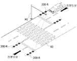
도 1은 본 발명의 실시예에 따른 횡단보도 안전 조명 시스템의 설치 구성도를 도시한 구성도,
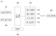
도 2는 도 1의 횡단보도 안전 조명 시스템의 블록도,
도 3은 도 1에서 차량 정지선의 색상 제어를 도시하는 사용상태도,
도 4는 도 1에서 횡단보도 대기선의 색상 제어를 도시하는 사용상태도,
도 5는 도 1에서 도로 표지병의 색상 제어의 일례를 도시하는 사용상태도,
도 6은 도 1에서 도로 표지병의 색상 제어의 다른 예를 도시하는 사용상태도,
도 7은 도 1에서 안개시 도로 표지병의 제어를 도시하는 사용상태도,
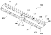
도 8은 도 1의 조명 장치를 도시한 사시도,
도 9는 도 8의 분해 사시도,
도 10은 도 7 및 도 8에서 제1기판과 제1덮개판을 도시한 분해 사시도,
도 11은 도 1 및 도 2의 도로 표지병의 블록도,
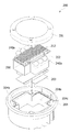
도 12는 도 1 및 도 2의 도로 표지병의 분해 사시도,
도 13은 도 12의 커버를 구체적으로 도시한 사시도, 그리고,
도 14는 도 1의 도로 표지병에 전력을 제공하는 태양광 장치의 블록도이다. 1 is a configuration diagram showing an installation configuration of a pedestrian crossing safety lighting system according to an embodiment of the present invention,
Figure 2 is a block diagram of the pedestrian crossing safety lighting system of Figure 1,
3 is a use state diagram showing the color control of the vehicle stop line in FIG. 1,
Figure 4 is a state diagram showing the color control of the pedestrian crossing line in Figure 1,
Figure 5 is a use state diagram showing an example of the color control of the road sign bottle in Figure 1,
6 is a use state diagram showing another example of color control of the road sign bottle in FIG. 1,
7 is a use state diagram showing the control of the road sign bottle during the fog in FIG. 1,
8 is a perspective view showing the lighting device of FIG. 1,
9 is an exploded perspective view of FIG. 8,
10 is an exploded perspective view showing the first substrate and the first cover plate in FIGS. 7 and 8,
11 is a block diagram of the road sign bottles of FIGS. 1 and 2,
12 is an exploded perspective view of the road sign bottle of FIGS. 1 and 2,
13 is a perspective view specifically showing the cover of FIG. 12, and
14 is a block diagram of a solar device providing power to the road sign bottle of FIG. 1.
이하, 첨부한 도면을 참고로 하여 본 발명의 실시예에 대하여 본 발명이 속하는 기술분야에서 통상의 지식을 가진 자가 용이하게 실시할 수 있도록 상세히 설명한다. 본 발명은 여러 가지 상이한 형태로 구현될 수 있으며 여기에서 설명하는 실시예에 한정되지 않는다. 도면에서 본 발명을 명확하게 설명하기 위해서 설명과 관계없는 부분은 생략하였으며, 명세서 전체를 통하여 동일 또는 유사한 구성요소에 대해서는 동일한 참조부호를 붙였다.Hereinafter, exemplary embodiments of the present invention will be described in detail with reference to the accompanying drawings so that those skilled in the art to which the present invention pertains can easily practice. The present invention can be implemented in many different forms and is not limited to the embodiments described herein. In the drawings, parts not related to the description are omitted in order to clearly describe the present invention, and the same reference numerals are attached to the same or similar elements throughout the specification.
이하에서는 도면을 참조하여 본 발명의 실시예에 따른 횡단보도 안전 조명 시스템을 보다 상세히 설명하도록 한다. 도 1은 본 발명의 실시예에 따른 횡단보도 안전 조명 시스템의 설치 구성도를 도시한 구성도이고, 도 2는 도 1의 횡단보도 안전 조명 시스템의 블록도이다. Hereinafter, a pedestrian crossing safety lighting system according to an embodiment of the present invention will be described in detail with reference to the drawings. 1 is a block diagram of an installation configuration of a pedestrian crossing safety lighting system according to an embodiment of the present invention, and FIG. 2 is a block diagram of the pedestrian crossing safety lighting system of FIG. 1.
도 1 및 도 2를 참조하면, 본 발명의 일 실시예에 따른 횡단보도 안전 조명 시스템(10)은 조명 장치(100), 도로 표지병(200), 시스템 제어부(300), 위치 감지 센서(400), 및 알람부(500)를 포함한다. 1 and 2, the pedestrian crossing
이와 같은 횡단보도 안전 조명 시스템(10)은 횡단보도에 설치되어 횡단보도 대기선(B1) 및 차량정지선(B2)에 광을 조사하여 일정색의 조명라인을 형성하고, 차량이 차량정지선(B2)을 초과하는 경우 차량으로 경고를 전송할 수 있다.Such a pedestrian crossing
조명 장치(100)는 도로변에 수직하게 설치되는 지주(H1)로부터 도로측으로 일정길이 연장되는 수평바(H2)에 설치되는 신호표지판과 같은 교통안전시설물(H3)에 설치된다. 여기서, 교통안전시설물(H3)은 차량용 교통신호들일 수 있다. 이러한 조명 장치(100)는 제1조명부(120) 및 제2조명부(130)를 포함한다. The
제1조명부(120)는 횡단보도 대기선(B1)에 광을 조사할 수 있다. 이때, 제1조명부(120)는 횡단보도 대기선(B1)이 일정색으로 표시되도록 제1조명라인을 형성할 수 있다. 여기서, 제1조명부(120)는 녹색 또는 적색 광을 발광할 수 있다.The
대안적으로, 제1조명부(120)는 보행자가 보행하게 되는 횡단보도를 밝게 비추도록 그 일부가 횡단보도라인(B3)을 조사할 수 있다. Alternatively, the
제2조명부(130)는 차량 정지선(B2)에 광을 조사할 수 있다. 이때, 제2조명부(130)는 차량 정지선(B2)이 일정색으로 표시되도록 제2조명라인을 형성할 수 있다. 여기서, 제1조명부(120)는 녹색 또는 적색 광을 발광할 수 있다.The
한편, 조명 장치(100)는 RF 송신부(150) 및 조도 센서(140)를 더 포함할 수 있다. Meanwhile, the
RF 송신부(150)는 도로 표지병(200)으로 제어 신호를 전송할 수 있다. 여기서, 제어 신호는 도로 표지병(200)의 발광색 및 점멸을 제어하기 위한 신호일 수 있다. 이러한 제어 신호는 후술하는 바와 같은 시스템 제어부(300)에 의해 제공될 수 있다.The
조도 센서(140)는 조명 장치(100)에서 도로면을 향하도록 배치될 수 있다. 이때, 조도 센서(140)는 주변의 조도를 감지할 수 있다. The
도로 표지병(200)은 차량이 주행하는 도로의 차선을 따라 복수개로 설치될 수 있다. 이때, 도로 표지병(200)은 차량 정지선(B2)으로부터 일정 거리 이내에 설치될 수 있다. 여기서, 도로 표지병(200)은 중앙선 및 도로 가장자리의 경계선에 일정 간격으로 매설될 수 있다. The
또한, 도로 표지병(200)은 차량의 운전자가 차선을 식별할 수 있도록 일정색을 발광할 수 있다. 여기서, 도로 표지병(200)은 녹색 및 적색 광을 발광할 수 있다. 이때, 도로 표지병(200)은 RF 송신부(150)의 제어 신호에 따른 발광 색상 및 점멸 주기 또는 점등 및 소등 주기로 동작될 수 있다.In addition, the
시스템 제어부(300)는 횡단보도에 설치된 보행자 신호등의 신호색에 따라 조명 장치(100) 및 도로 표지병(200)을 발광색을 제어할 수 있다. 즉, 시스템 제어부(300)는 제1조명라인 및 제2조명라인의 색상을 제어하고 복수의 도로 표지병(200)의 발광색 및 발광 주기를 제어할 수 있다.The
또한, 시스템 제어부(300)는 위치 감지 센서(400)를 통하여 차량이 차량 정지선(B2)을 넘었는지를 판단할 수 있다. 이때, 시스템 제어부(300)는 위치 감지 센서(400)로부터 차량이 차량 정지선(B2)을 넘어섰다고 감지한 경우, 차량에 경고하도록 알람부(500)를 제어할 수 있다.In addition, the
또한, 시스템 제어부(300)는 조도 센서(140)에서 감지된 조도가 임계값 이하인지를 판단하여 임계값 이하로 감소한 경우, 복수의 도로 표지병(200)이 차량의 진행방향을 따라 순차적으로 발광하도록 제어할 수 있다.In addition, the
위치 감지 센서(400)는 차량 정지선(B2)의 양측에 매설될 수 있다. 이러한 위치 감지 센서(400)는 차량의 위치를 감지할 수 있다. 이때, 위치 감지 센서(400)는 차량이 차량 정지선(B2)을 넘어섰는지의 여부를 감지할 수 있다.The
알람부(500)는 보행 신호시 차량이 차량 정지선(B2)을 넘어서는 경우, 시스템 제어부(300)의 제어에 따라 차량에 경고할 수 있다. The
보다 구체적으로, 보행자 신호등의 보행 신호시, 차량이 차량 정지선(B2)을 넘는 경우, 위치 감지 센서(400)는 차량이 차량 정지선(B2)을 넘어섰음을 감지할 수 있다. 이때, 시스템 제어부(300)는 차량에 경고하도록 알람부(500)를 제어할 수 있다.More specifically, when a pedestrian signals a pedestrian signal, when the vehicle crosses the vehicle stop line B2, the
여기서, 알람부(500)는 차량으로 음성 경고를 수행하는 스피커일 수 있다. 이러한 스피커는 보행자 신호등의 지주 또는 교통안전시설물(H3)이 설치되는 지주(H1)에 설치될 수 있다. 또한, 알람부(500)는 조명 장치(100)에 설치될 수 있다.Here, the
대안적으로, 알람부(500)는 차량 내의 스피커를 통하여 음성 경고되도록 차량으로 경고신호를 발송할 수 있다. 이때, 알람부(500)는 차량과 통신이 가능한 통신 수단일 수 있다. Alternatively, the
이에 의해, 운전자가 차량 정지선(B2)을 용이하게 인식할 수 있으므로 차량 정지선(B2)을 준수할 수 있게 함으로써 보행자의 안전을 보장할 수 있다. Thereby, since the driver can easily recognize the vehicle stop line B2, it is possible to ensure the safety of the pedestrian by allowing the vehicle stop line B2 to be observed.
이와 같은 횡단보도 안전 조명 시스템(10)은 횡단보도에 설치된 보행자 신호등의 신호색에 따라 제1조명라인, 제2조명라인 및 복수의 도로 표지병(200)의 발광색을 제어할 수 있다.The pedestrian crossing
도 3은 도 1에서 차량 정지선의 색상 제어를 도시하는 사용상태도이다. FIG. 3 is a use state diagram showing color control of a vehicle stop line in FIG. 1.
보행자 신호등이 보행 신호인 경우, 즉, 녹색등이 점등되고, 차량용 신호등이 적색등이 점등된 경우, 차량 정지선(B2)에 대응하는 제2조명라인이 적색을 형성함으로써, 운전자가 보행자 신호등 또는 차량용 교통신호등에 더하여 차량을 정지해야 함을 인식할 수 있다. When the pedestrian traffic light is a pedestrian signal, that is, when the green light is on and the traffic light for the vehicle is on, the second light line corresponding to the vehicle stop line B2 forms red, thereby allowing the driver to In addition to traffic lights, it can be recognized that the vehicle must be stopped.
이때, 시스템 제어부(300)는 신호등 제어기(20)에 의해 제2조명부(130)가 적색을 발광하도록 제어할 수 있다. 즉, 제2조명라인(B2-R)은 도로면에서 적색을 형성할 수 있다.In this case, the
도 4는 도 1에서 횡단보도 대기선의 색상 제어를 도시하는 사용상태도이다. 4 is a state diagram showing the color control of the pedestrian crossing line in FIG.
보행자 신호등이 보행 신호인 경우, 즉, 녹색등이 점등되고, 차량용 교통신호등이 적색등이 점등된 경우, 횡단보도 대기선(B1)에 대응하는 제1조명라인이 녹색을 형성함으로써, 보행자는 보행을 인식하고, 운전자는 차량을 정지해야 함을 인식할 수 있다.When the pedestrian traffic light is a pedestrian signal, that is, when the green light is on and the traffic light for a vehicle is on, the first light line corresponding to the pedestrian crossing waiting line B1 is green, thereby allowing the pedestrian to walk. , And the driver can recognize that the vehicle should be stopped.
이때, 시스템 제어부(300)는 신호등 제어기(20)에 의해 제1조명부(120)가 녹색을 발광하도록 제어할 수 있다. 즉, 제1조명라인(B1-G)은 도 4의 좌측과 같이 도로면에서 녹색을 형성할 수 있다.In this case, the
반대로, 보행자 신호등이 정지 신호인 경우, 즉, 적색등이 점등되고, 차량용 교통신호등이 녹색등이 점등된 경우, 횡단보도 대기선(B1)에 대응하는 제1조명라인이 적색을 형성함으로써, 보행자는 신호 대기를 인식하고, 운전자는 정상적인 차량 운행을 인식할 수 있다.Conversely, when the pedestrian traffic light is a stop sign, that is, when the red light is on and the traffic light for vehicles is on, the first light line corresponding to the pedestrian crossing waiting line B1 forms red, Recognizes signal waiting, and the driver can recognize normal vehicle operation.
이때, 시스템 제어부(300)는 신호등 제어기(20)에 의해 제1조명부(120)가 적색을 발광하도록 제어할 수 있다. 즉, 제1조명라인(B1-L)은 도 4의 우측과 같이 도로면에서 적색을 형성할 수 있다.In this case, the
도 5는 도 1에서 도로 표지병의 색상 제어의 일례를 도시하는 사용상태도,Figure 5 is a use state diagram showing an example of the color control of the road sign bottle in Figure 1,
보행자 신호등이 보행 신호인 경우, 즉, 녹색등이 점등되고, 차량용 교통신호등이 적색등이 점등된 경우, 도로 표지병(200)이 적색을 발광함으로써, 보행자는 보행을 인식하고, 운전자는 차량을 정지해야 함을 인식할 수 있다.When the pedestrian traffic light is a pedestrian signal, that is, when the green light is on and the traffic light for the vehicle is on, the
이때, 시스템 제어부(300)는 신호등 제어기(20)에 의해 도로 표지병(200)이 적색을 발광하도록 제어할 수 있다. 즉, 도로 표지병(200)은 도로면에서 적색(200-R)을 발광할 수 있다.At this time, the
도 6은 도 1에서 도로 표지병의 색상 제어의 다른 예를 도시하는 사용상태도이다. 6 is a use state diagram showing another example of color control of the road sign bottle in FIG. 1.
보행자 신호등이 정지 신호인 경우, 즉, 적색등이 점등되고, 차량용 교통신호등이 녹색등이 점등된 경우, 도로 표지병(200)이 녹색을 형성함으로써, 보행자는 신호 대기를 인식하고, 운전자는 정상적인 차량 운행을 인식할 수 있다.When the pedestrian traffic light is a stop sign, that is, when the red light is on and the traffic light for the vehicle is green, the
이때, 시스템 제어부(300)는 신호등 제어기(20)에 의해 도로 표지병(200)이 녹색을 발광하도록 제어할 수 있다. 즉, 도로 표지병(200)은 도로면에서 녹색(200-R)을 발광할 수 있다.In this case, the
이와 같이, 횡단보도 대기선(B1)에 대한 제1조명라인은 보행자 신호등과 . 동일한 색상을 발광하고, 차량 정지선(B2)에 대한 제2조명부(130) 및 도로 표지병(200)은 보행자 신호등과 상이한 색상을 발광한다. 즉, 제1조명라인은 보행자 신호등과 동일한 색상으로 발광하고, 제2조명라인 및 도로 표지병(200)은 차량용 교통신호등과 동일한 색상으로 발광될 수 있다.As such, the first lighting line for the pedestrian crossing waiting line (B1) is a pedestrian traffic light. The same color emits light, and the
이에 의해, 보행자는 횡단보도 및 횡단보도 대기선(B1)을 용이하게 식별할 수 있고, 운전자는 횡단보도 및 차량 정지선(B2)을 용이하게 식별할 수 있으므로 보행자의 안전을 보장할 수 있어 교통사고를 미연에 방지할 수 있다. Thereby, the pedestrian can easily identify the pedestrian crossing and the pedestrian crossing waiting line (B1), and the driver can easily identify the pedestrian crossing and the vehicle stop line (B2), thereby ensuring the safety of the pedestrian, thus preventing traffic accidents. Can be prevented.
도 7은 도 1에서 안개시 도로 표지병의 제어를 도시하는 사용상태도이다. FIG. 7 is a use state diagram showing control of a road sign bottle during fog in FIG. 1.
주간에 안개 등으로 인하여 조도가 임계값 이하로 감소하는 경우, 도로 표지병(200)이 차량의 진행방향을 따라 순차적으로 발광함으로써, 횡단보도로 진입하는 차량의 운전자가 횡단보도에 근접함을 용이하게 식별할 수 있다.When the illuminance decreases below a threshold due to fog during the daytime, the
이때, 시스템 제어부(300)는 조도 센서(140)에 의해 감지 결과에 따라 조도가 임계값 이하로 판단되면, 도로 표지병(200)이 점멸하도록 제어할 수 있다. 여기서, 도로 표지병(200)은 차량의 진행방향을 따라 순차적으로 발광할 수 있다. At this time, the
즉, 차량 정지선(B2)으로부터 가장 먼 위치의 도로 표지병(200)으로부터 차량 정지선(B2)에 가장 근접한 위치의 도로 표지병(200)으로 점멸방향이 형성됨으로서, 차량의 진행방향과 동이하게 도로 표지병(200)의 점멸방향이 형성될 수 있다.That is, the blinking direction is formed from the
이하, 도 8 내지 도 9를 참조하여 조명 장치(100)를 더 상세하게 설명한다. 도 8은 도 1의 조명 장치를 도시한 사시도이고, 도 9는 도 8의 분해 사시도이며, 도 10은 도 7 및 도 8에서 제1기판과 제1덮개판을 도시한 분해 사시도이다. Hereinafter, the
조명 장치(100)는 방열부재(110), 제1조명부(120) 및 제2조명부(130)를 포함할 수 있다.The
방열부재(110)는 횡단보도 및 정지선이 표시되는 도로와 마주하는 일측면에 일정깊이의 배치부(112)를 함몰형성하여 교통안전시설물에 착탈가능하게 조립될 수 있다. The
이러한 방열부재(110)는 신호표지판과 같은 교통안전시설물(H3)의 하부에 직,간접적으로 조립된다. The
제1조명부(120) 및 제2조명부(130)가 설치되는 방열부재(110)는 조명시 발생하는 열을 외부로 방출할 수 있도록 외부면에 외측으로 경사지게 연장되는 복수개의 방열핀(114)을 돌출형성하고, 알루미늄과 같은 열전도성이 높은 소재로 이루어지는 것이 바람직하다. The
제1조명부(120)는 방열부재에 함몰형성된 배치부(112)에 삽입배치되는 전원공급장치(118)와 전기적으로 연결되어 전원인가시 빛을 발생시키는 복수개의 제1엘이디(122)를 갖는 제1기판(124)을 포함하고, 제1기판(124)을 덮어 보호하는 제1덮개판(128)에는 제1엘이디(122)의 발광시 발생한 빛을 횡단보도라인(B3)측으로 조사하여 보행자가 보행하게 되는 횡단보도를 밝게 비추도록 복수개의 제1엘이디와 대응하는 영역마다 복수개의 비구면렌즈(126)를 돌출 형성한다. The
이에 따라, 제1조명부(120)가 횡단보도라인(B3)의 직상부에 해당하는 교통안전시설물(H3)에 구비된 방열부재(110)에 설치되지 않고, 횡단보도로부터 일정거리 이격된 교통안전시설물에 구비된 방열부재에 설치된 상태에서 제1기판의 제1엘이디(122)에서 발생하는 빛은 제1덮개판의 비구면렌즈(126)에 굴절된 다음, 교통안전시설물(H1)의 직하부의 도로면으로부터 일정거리 이격된 도로에 표시된 횡단보도라인(B3)을 밝게 조명하도록 경사지게 비추어질 수 있는 것이다.Accordingly, the
이때, 제1기판(124)의 제1엘이디(122)에서 발생하는 빛의 굴절각도는 다양한 굴절각도를 갖도록 비구면렌즈(126)를 돌출형성한 제1덮개판(128)의 간편한 교체작업에 의해서 설치조건에 따라 조절될 수 있다. At this time, the refractive angle of the light generated by the first LED 122 of the
그리고 제1기판(124)은 배치부(112)의 입구 좌우양측에 형성되는 탑재면(116) 중 어느 일측에 밀착되도록 복수개의 체결부재에 의해서 고정설치됨으로써 제1엘이디(122)의 발광시 발생하는 열은 탑재면(116)을 형성한 방열부재측으로 열전달되어 외부로 방출될 수 있는 것이다. In addition, the
제2조명부(130)는 방열부재(110)에 함몰형성된 배치부(112)에 삽입배치되는 전원공급장치(118)와 전기적으로 연결되어 전원인가시 빛을 발생시키는 복수개의 제2엘이디(132)를 갖는 제2기판(134)을 포함하고, 제2기판(124)을 덮어 보호하는 제2덮개판(138)에는 제2엘이디(132)의 발광시 발생한 빛을 횡단보도라인(B3)로부터 일정거리 이격된 차량 정지선(B2)측으로 조사하여 일자형 제2조명라인을 비추도록 복수개의 제2엘이디(132)와 대응하는 영역에 라인형성용 일자형 도광렌즈(136)를 형성할 수 있다. The
여기서, 제2엘이디(132)는 전원인가시 적색광이나 녹색광을 발광시키는 엘이디소자로 구비되는 것이 바람직하다. Here, the
이에 따라, 제1조명부(120)와 마찬가지로 제2조명부(130)도 차량 정지선(B2)으로부터 일정거리 이격된 교통안전시설물에 구비된 방열부재(110)에 설치된 상태에서, 제2기판(134)의 제2엘이디(132)에서 발생하는 빛은 제2덮개판의 라인형성용 일자형 도광렌즈(136)에 굴절되면서 일자헝 라인조명으로 전환된 다음, 교통안전시설물(H1)의 직하부의 도로면으로부터 일정거리 이격된 도로에 표시되는 차량 정지선(B2)과 나란한 일자형 제2조명라인을 형성하게 되는 것이다. Accordingly, like the
이때, 제2기판의 제2엘이디(132)에서 발생하는 빛의 굴절각도는 다양한 굴절각도를 갖도록 라인형성용 일자형 도광렌즈(136)를 돌출형성하는 제2덮개판(138)의 간편한 교체작업에 의해서 적절히 조절될 수 있다. At this time, the refractive angle of the light generated by the
그리고 제2기판(134)은 제1기판과 마찬가지로 배치부(112)의 입구 좌우양측에 형성되는 탑재면(116) 중 나머지 일측에 밀착되도록 복수개의 체결부재에 의해서 고정설치됨으로써 제2엘이디의 발광시 발생하는 열은 방열부재측으로 열전달되어 방출될 수 있는 것이다. And the
한편, 방열부재(110)의 배치부(112)에는 차량이 도로를 주행하고, 보행자가 횡단보도를 보행하는 교통상황을 영상으로 촬영하는 적어도 하나의 카메라(142)를 삽입배치하여 고정설치하고, 배치부(112)의 입구 좌우양측에 구비되는 탑재면(116)의 일측에는 카메라(112)를 이용한 영상촬영을 위하여 조명을 제공하는 제3조명부(144)를 구비하며, 카메라(142)에는 주간 및 야간에도 영상촬영이 가능하도록 주간용 데이필터와 야간용 데이필터가 주,야간마다 교체되는 데이-나이트필터를 구비하는 것이 바람직하다. On the other hand, the
이에 따라, 도로를 주행하거나 차량 정지선에 정지하게 되는 차량의 주행상태와 횡단보도를 통행하게 되는 보행자의 보행상태는 카메라에 의해서 영상으로 촬영되고, 촬영된 영상은 관제실로 무선 또는 유선으로 전송되어 모니터에서 출력되어 확인되거나 서버에 저장하게 되는 것이다. Accordingly, the driving state of the vehicle driving on the road or stopped on the vehicle stop line and the pedestrian walking state of passing the pedestrian crossing are captured by an image by a camera, and the captured image is transmitted wirelessly or wired to the control room for monitoring. It will be printed out and verified or stored in the server.
또한, 탑재면(116)의 타측에는 상술한 바와 같은 조도 센서(140) 및 RF 송신부(150)가 구비될 수 있다. In addition, an
그리고 방열부재(110)에는 배치부의 입구를 덮어 보호하는 수평투명판(161)과, 배치부(112)의 양측 개구된 양단을 밀폐하도록 수평투명판의 양단으로부터 절곡되는 수직투명판(162)을 포함하는 덮개부재를 구비한다.In addition, the
이에 따라, 덮개부재(160)에 의해 배치부(112)가 외부환경과 차단됨으로써, 배치부에 삽입배치되어 고정설치되는 전원공급장치(118) 및 카메라(142)가 외부환경에 의해서 오염되거나 손상되는 것을 방지하고, 그 사용수명을 연장할 수 있는 것이다. Accordingly, the
여기서, 전원공급장치(118)는 제1,2 및 3조명부에 구비되는 엘이디에 외부전원을 안정적으로 공급하는 것으로, 이러한 전원공급장치(118)는 외부에서 공급되는 상용전원의 교류전류를 직류전류로 전환시킨 후 엘이디에 공급하는 스위칭 모드 파워 서플라이(Switching Mode Power Supply)가 선택적으로 사용될 수 있다. 또한, 전원공급장치(118)는 태양광 장치(600)로부터 전원을 공급받고 변압하여 전력을 제공할 수도 있다. Here, the
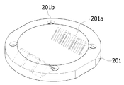
이하, 도 10 내지 도 13을 참조하여, 도로 표지병(200)을 더 상세하게 설명한다. 도 11은 도 1 및 도 2의 도로 표지병의 블록도이고, 도 12는 도 1 및 도 2의 도로 표지병의 분해 사시도이며, 도 13은 도 12의 커버를 구체적으로 도시한 사시도이다. Hereinafter, the
도로 표지병(200)은 태양광 집광부(210), 충전 배터리(220), 전원 제어부(230), LED 모듈(240), RF 수신부(250), 제어부(260) 및 시계부(270)를 포함한다. The
태양광 집광부(210)는 태양광으로부터 전력을 생성하여 충전 배터리(220)를 충전할 수 있다. 이러한 태양광 집광부(210)는 태양광 셀(212) 및 충전부(214)를 포함할 수 있다.The solar
태양광 셀(212)은 태양광을 집광하여 전력을 생성할 수 있다. 이러한 태양광 셀(212)은 후술하는 바와 같이 도로 표지병(200)의 상부에 구비될 수 있다. 즉, 태양광 셀(212)은 도로(20) 상에서 외부로 노출된 부위에 구비될 수 있다.The
충전부(214)는 태양광 셀(212)로부터 생성된 전력을 충전 배터리(220)를 충전하기 적합한 전압으로 변환하여 충전 배터리(220)를 충전할 수 있다.The charging
충전 배터리(220)는 태양광 집광부(210)로부터 공급되는 전력에 의해 충전될 수 있다. 또한, 충전 배터리(220)는 LED 모듈(240)에 전원을 공급할 수 있다. 물론 충전 배터리(220)는 다른 구성요소들, 예컨대, 전원 제어부(230), RF 수신부(250), 제어부(260) 및 시계부(270)에도 전원을 공급할 수 있다.The charging
전원 제어부(230)는 충전 배터리(220)의 전원을 LED 모듈(240)로 공급하거나 차단할 수 있다. 결과적으로 전원 제어부(230)는 LED 모듈(240)의 점멸 주기를 제어할 수 있다.The
또한, 전원 제어부(230)는 충전 배터리(220)의 충전 상태에 따라 충전 배터리(220)가 완전 방전되지 않도록 LED 모듈(240)의 동작을 제어할 수 있다. 즉, 전원 제어부(230)는 충전 배터리(220)의 충전 상태에 따라 순차적으로 LED 모듈(240)의 광량, 점멸 주기, 발광 시간 및 강제 오프 중 어느 하나를 제어할 수 있다. 이때, 순차적인 제어는 도로 표지병(200)의 설치 규정, 또는 충전 배터리(220)의 잔여 전원 공급시간 등을 고려하여 규정을 준수하면서도 최소 전력만을 소비하도록 제어하기 위한 것이다. In addition, the
일례로, 전원 제어부(230)는 충전 배터리(220)의 충전 상태가 제1임계값 이하이면 LED 모듈(240)의 광량을 감소시킬 수 있다. 여기서, 도로 표지병(200)은 지속적으로 광을 발산하도록 규정되어 있기 때문에 LED 모듈(240)이 지속적으로 발광하면서도 소비전력을 감소시키기 위하여 전원 제어부(230)는 LED 모듈(240)의 광량만을 감소시킬 수 있다.For example, the
LED 모듈(240)은 전원 제어부(230)의 제어에 따라 충전 배터리(220)로부터 전원을 공급받아 발광할 수 있다. 이러한 LED 모듈(240)은 태양광 셀(212)의 좌우 측부에 구비될 수 있다.The
또한, LED 모듈(240)은 적어도 2색상 중 하나를 발광할 수 있다. 일례로, LED 모듈(240)은 보행자 신호등이 정지 신호인 경우 녹색을 발광하고, 보행자 신호등이 보행 신호인 경우 적색을 발광할 수 있다.Also, the
RF 수신부(250)는 RF 송신부(150)로부터 제어 명령을 수신할 수 있다. 즉, RF 수신부(250)는 조명 장치(100)와 통신을 수행할 수 있다. The
제어부(260)는 RF 수신부(250)에서 수신되는 제어 명령에 따라 LED 모듈(240)의 동작을 제어할 수 있다. 즉, 제어부(260)는 보행자 신호등의 신호에 의한 제어 명령에 따라 LED 모듈(240)의 점멸 또는 발광색을 제어할 수 있다.The
또한, 제어부(260)는 시계부(270)의 시각 정보를 기초로 LED 모듈(240)의 동작 주기를 제어할 수 있다. 여기서, 도로 표지병(200)은 도로 상에서 복수 개가 구비되어 발광 패턴을 형성하기 때문에 서로 동일한 시간을 기준으로 제어되어야 한다. 이를 위해, 제어부(260)는 시계부(270)의 시각 정보를 다른 도로 표지병(200)의 시각 정보와 동기화시킬 수 있다. In addition, the
시계부(270)는 시각 정보를 제공할 수 있다. 여기서, 시각 정보는 LED 모듈(240)의 점멸을 제어하기 위한 기준 시각일 수 있다. 이러한 시계부(270)는 내부에 클록 발생 장치를 포함할 수 있다. 또한 시계부(270)는 제어부(260)에 의해 다른 도로 표지병(200)의 시계부와 동기화될 수 있다. The
또한, 도로 표지병(200)은 커버(201), 본체 모듈(202) 및 케이스(204)를 포함할 수 있다.Also, the
커버(201)는 도로 표지병(200)이 도로에 삽입된 상태에서 외부로 돌출되는 부분으로 LED 모듈(240)로부터 발광된 광을 외부로 발산할 수 있다.The
본체 모듈(202)은 케이스(204)의 내부에 배치되며, 도 11을 참조하여 상술한 바와 같은 구성요소들을 포함할 수 있다.The
케이스(204)는 커버(201)의 하측에 배치되어 커버(201)와 결합될 수 있다. 이러한 케이스(204)는 도로에서 매립된 부분일 수 있다. The
도 13에 도시된 바와 같이, 커버(201)는 결합용 홀(201b) 및 발산부(201a)를 포함할 수 있다. 여기서 커버(201)는 태양광이 입사되거나 LED 모듈(240)에서 발광된 광을 발산하도록 그 중앙부는 투명재질로 이루어질 수 있다. 13, the
결합용 홀(201b)은 커버(201)를 관통하여 형성될 수 있다. 이 결합용 홀(201b)에 볼트와 같은 체결수단을 삽입함으로써 커버(201)와 케이스(204)가 결합될 수 있다.The
발산부(201a)는 LED 모듈(240)로부터 발산된 광을 굴절시켜 외부로 발산하도록 계단식 구조를 가질 수 있다. 즉, 발산부(201a)는 커버(201)의 하측, 즉, 본체 모듈(202) 측이 개방된 개구면이 구비되고, 개구면과 일정 각도로 기울어진 경사면이 구비될 수 있다. 여기서, 경사면은 계단식 구조를 가질 수 있다. 또한 발산부(201a)는 경사면과 일정 각도를 이루진 출사면을 구비할 수 있다. 이러한 발산부(201a)는 대략 삼각형 상으로 구비될 수 있다. The diverging
이러한 발산부(201a)에 의해, 커버(201)의 하부에 배치된 LED 모듈(240)로부터 상기 개구면으로부터 유입된 광은 계단 구조를 갖는 경사면에서 굴절되어 출사면을 통하여 외부로 발산될 수 있다.By the
본체 모듈(202)은 상측에 태양광 셀(212)이 구비되고, 측면으로 돌출된 측부(202b)의 상단에서 경사진 LED 모듈(240)이 구비될 수 있다. 이때, LED 모듈(240)은 측부(202b)에서 경사진 각도로 광을 출력하도록 사선 방향으로 배치될 수 있다.The
또한, 본체 모듈(202)은 태양광 셀(212)의 일측에 상술한 바와 같은 RF 수신부(250)가 구비될 수 있다. In addition, the
또한, 본체 모듈(202)은 도 11을 참조하여 상술한 바와 같은 회로 구성부를 구비한 회로기판(203)이 구비될 수 있다. 이러한 회로기판(203)은 본체 모듈(202)의 하부 또는 내부에 구비될 수 있다. 여기서, 회로기판(203)은 충전 배터리(220), 전원 제어부(230), 제어부(260), 및 시계부(270)가 실장될 수 있다. In addition, the
케이스(204)는 안착부(204a), 홈부(205b) 및 결합용 홀(204c)을 포함할 수 있다. 여기서, 케이스(204)는 부식을 방지하도록 알루미늄 재질로 이루어질 수 있다. The
안착부(204a)는 케이스(204)의 중앙부에 구비될 수 있다. 이러한 안착부(204a)는 본체 모듈(202)이 삽입 안착될 수 있다. 또한 안착부(204a)는 본체 모듈(202)의 외형에 대응하는 형상을 가질 수 있다. 일례로, 안착부(204a)는 대략 십자 형상으로 구비될 수 있다. 이때, 안착부(204a)의 길이방향은 본체 모듈(202)의 중앙부가 안착되며, 폭방향은 본체 모듈(202)의 측부(202b)가 안착될 수 있다.The
홈부(204b)는 안착부(204a)의 외주변을 따라 구비될 수 있다. 이 홈부(204b)에는 방수 고무링이 삽입될 수 있다.The
결합용 홀(204c)은 커버(201)의 결합용 홀(201b)에 대응하는 위치에 구비될 수 있다. 여기서 결합용 홀(204c)은 홈부(204b)의 외측에 구비될 수 있다. 이에 의해 방수 고무링이 커버(201)와 케이스(204) 사이에 형성되는 이격 공간에서 외부로부터의 이물질의 유입을 방지할 수 있다.The
한편, 도로 표지병(200)은 도로면에 매설되기 때문에 건물 등 주변의 시설물에 의해 그늘이 발생하여 자가 충전이 곤란한 경우, 외부로부터 공급되는 전력에 의해 충전 배터리(220)를 충전할 수 있다 .On the other hand, since the
이때, 횡단보도 안전 조명 시스템(10)은 태양광 장치(600)를 더 포함할 수 있다. 도 14는 도 1의 도로 표지병에 전력을 제공하는 태양광 장치의 블록도이다. In this case, the pedestrian crossing
태양광 장치(600)는 태양광 집광모듈(610), 배터리(620), 전원 제어 모듈(630) 및 변압부(640)를 포함할 수 있다.The
태양광 집광모듈(610)은 보행자 신호등 또는 차량용 교통신호등의 지주(H1) 상단에 배치될 수 있다. 이러한 태양광 집광모듈(610)은 태양광을 집광하여 태양광으로부터 전력을 생성할 수 있다. The solar
이때, 태양광 집광모듈(610)은 태양광 셀모듈(612) 및 충전 모듈(614)을 포함할 수 있다.At this time, the solar
태양광 셀모듈(612)은 태양광을 집광하여 전력을 생성할 수 있다. 이러한 태양광 셀모듈(612)은 보행자 신호등 또는 차량용 교통신호등의 지주(H1) 상단에 배치될 수 있다.The
충전 모듈(614)은 태양광 셀모듈(612)로부터 생성된 전력을 배터리(620)를 충전하기 적합한 전압으로 변환하여 배터리(620)를 충전할 수 있다.The
배터리(620)는 태양광 집광모듈(610)로부터 공급되는 전력에 의해 충전될 수 있다. 또한 배터리(620)는 도로 표지병(200)에 전력을 공급할 수 있다. 물론, 배터리(620)는 다른 구성요소들, 예컨대, 조명 장치(100), 시스템 제어부(300), 위치 감지 센서(400), 및 알람부(500)에도 전원을 공급할 수 있다.The
전원 제어 모듈(630)은 도로 표지병(200)의 전력 상태를 감지하여 배터리(620)의 전력을 도로 표지병(200)으로 인가하도록 제어할 수 있다. 즉, 전원 제어 모듈(630)는 도로 표지병(200)의 충전 배터리(220)의 충전 상태를 감지하여 일정값 이하인 경우, 배터리(620)의 전원을 도로 표지병(200)으로 인가하도록 제어할 수 있다.The
변압부(640)는 배터리(620)의 전력을 전원 제어 모듈(630)의 제어에 따라 변환할 수 있다. 이때, 변압부(640)는 도로 표지병(200)의 전원으로 변환할 수 있다. 즉, 변압부(640)는 배터리(620)의 전압을 도로 표지병(200)의 충전 배터리(220)의 전압으로 변압하여 복수의 도로 표지병(200-1~200-4)으로 공급할 수 있다.The
이상에서 본 발명의 일 실시예에 대하여 설명하였으나, 본 발명의 사상은 본 명세서에 제시되는 실시예에 제한되지 아니하며, 본 발명의 사상을 이해하는 당업자는 동일한 사상의 범위 내에서, 구성요소의 부가, 변경, 삭제, 추가 등에 의해서 다른 실시예를 용이하게 제안할 수 있을 것이나, 이 또한 본 발명의 사상범위 내에 든다고 할 것이다.Although one embodiment of the present invention has been described above, the spirit of the present invention is not limited to the embodiments presented herein, and those skilled in the art to understand the spirit of the present invention may add elements within the scope of the same spirit. However, other embodiments may be easily proposed by changing, deleting, adding, or the like, but it will also be considered to fall within the scope of the present invention.
10 : 횡단보도 안전 조명 시스템
100 : 조명 장치
110 : 방열부재
120 : 제1조명부
130 ; 제2조명부
140 : 조도 센서
150 : RF 송신부
200 : 도로 표지병
300 : 시스템 제어부
400 : 위치 감지 센서
500 : 알람부
600 : 태양광 장치10: pedestrian crossing safety lighting system 100: lighting device
110: heat radiating member 120: first lighting unit
130; 2nd lighting unit 140: Illumination sensor
150: RF transmitter 200: road sign bottle
300: system control unit 400: position detection sensor
500: alarm unit 600: solar device
Claims (7)
상기 조명 장치에 구비되어 상기 도로 표지병으로 제어 신호를 전송하는 RF 송신부;
상기 차량 정지선으로부터 일정 거리 이내의 중앙선 및 도로 경계선에 일정 간격으로 매설되어 일정색을 발광하는 복수의 도로 표지병;
상기 차량 정지선의 양측에 매설되어 차량의 위치를 감지하는 위치 감지 센서;
상기 차량이 상기 차량 정지선을 넘어서는 경우 상기 차량에 경고하는 알람부; 및
상기 횡단보도에 설치된 보행자 신호등의 신호색에 따라 상기 제1조명라인, 상기 제2조명라인 및 상기 복수의 도로 표지병의 발광색을 제어하고, 상기 보행자 신호등의 보행 신호시 상기 위치 감지 센서로부터 상기 차량이 상기 차량 정지선을 넘어섰다고 감지한 경우, 상기 차량에 경고하도록 제어하는 상기 알람부를 제어하는 시스템 제어부;를 포함하는 횡단보도 안전 조명 시스템. A first lighting unit that is irradiated to the pedestrian crossing waiting line to form a first lighting line so that the pedestrian crossing waiting line is displayed in a certain color, and a second lighting line to be irradiated to the vehicle stopping line to display the vehicle stopping line in a constant color. A lighting device installed in a traffic safety facility installed on a pedestrian crossing;
An RF transmitter provided in the lighting device and transmitting a control signal to the road sign bottle;
A plurality of road marking bottles buried at regular intervals within a predetermined distance from the vehicle stop line and at a predetermined distance to emit a certain color;
A position detection sensor embedded in both sides of the vehicle stop line to detect the position of the vehicle;
An alarm unit warning the vehicle when the vehicle crosses the vehicle stop line; And
Control the light emission color of the first lighting line, the second lighting line and the plurality of road sign bottles according to the signal color of the pedestrian traffic light installed on the pedestrian crossing, and when the pedestrian signal of the pedestrian traffic light, the vehicle from the position detection sensor And a system control unit controlling the alarm unit controlling to warn the vehicle when it is detected that the vehicle stop line is crossed.
상기 조명 장치는 도로면을 향하도록 배치되어 조도를 감지하는 조도 센서;를 더 포함하고,
상기 시스템 제어부는 조도가 임계값 이하로 감소하는 경우, 상기 복수의 도로 표지병이 상기 차량의 진행방향을 따라 순차적으로 발광하도록 제어하는 횡단보도 안전 조명 시스템. According to claim 1,
The lighting device further includes an illuminance sensor that is disposed to face the road surface to detect illuminance,
When the illuminance decreases below a threshold, the system control unit controls the plurality of road sign bottles to sequentially emit light along the traveling direction of the vehicle.
상기 알람부는 상기 차량으로 음성 경고를 수행하는 스피커이고, 상기 보행자 신호등의 지주 또는 상기 조명 장치에 설치되는 횡단보도 안전 조명 시스템. According to claim 1,
The alarm unit is a speaker that performs a voice warning to the vehicle, a pedestrian crossing safety lighting system installed in the pillar or the lighting device of the pedestrian traffic lights.
상기 알람부는 상기 차량 내의 스피커를 통하여 음성 경고되도록 상기 차량으로 경고신호를 발송하는 횡단보도 안전 조명 시스템. According to claim 1,
The alarm unit is a pedestrian crossing safety lighting system that sends a warning signal to the vehicle to be alerted through the speaker in the vehicle.
상기 시스템 제어부는 상기 보행자 신호등이 보행 신호인 경우, 상기 제1조명라인이 녹색을 발광하고, 상기 제2조명라인 및 상기 도로 표지병이 적색을 발광하도록 제어하고,
상기 보행자 신호등이 정지 신호인 경우, 상기 제1조명라인이 적색을 발광하고, 상기 제2조명라인 및 상기 도로 표지병이 녹색을 발광하도록 제어하는 횡단보도 안전 조명 시스템. According to claim 1,
When the pedestrian traffic light is a pedestrian signal, the system controller controls the first lighting line to emit green, and the second lighting line and the road sign bottle to emit red,
When the pedestrian traffic light is a stop sign, the pedestrian crossing safety lighting system that controls the first lighting line to emit red, and the second lighting line and the road sign to emit green.
상기 제1조명부는 일부가 횡단보도라인을 조사하는 횡단보도 안전 조명 시스템. According to claim 1,
The first lighting unit is a pedestrian crossing safety lighting system that partially irradiates the pedestrian crossing line.
상기 보행자 신호등 또는 차량용 교통신호등의 지주 상단에 배치되며 태양광을 집광하여 태양광으로부터 전력을 생성하여 태양광 집광모듈;
상기 태양광 집광모듈로부터 생성된 전력으로 충전되는 배터리;
상기 도로 표지병의 전력 상태를 감지하여 상기 배터리의 전력을 상기 도로 표지병으로 인가하도록 제어하는 전원 제어 모듈; 및
상기 배터리의 전력을 상기 도로 표지병의 전원으로 변환하는 변압부를 더 포함하는 횡단보도 안전 조명 시스템. According to claim 1,
A solar light collecting module that is disposed on a prop of a pedestrian traffic light or a vehicle traffic light and collects sunlight to generate power from sunlight;
A battery charged with electric power generated from the solar light collecting module;
A power control module that detects a power state of the road sign bottle and controls the battery to apply power to the road sign bottle; And
A crosswalk safety lighting system further comprising a transformer for converting the power of the battery into the power of the road sign bottle.
Priority Applications (1)
| Application Number | Priority Date | Filing Date | Title |
|---|---|---|---|
| KR1020180161680A KR20200073477A (en) | 2018-12-14 | 2018-12-14 | System for safely Lighting a Crosswalk |
Applications Claiming Priority (1)
| Application Number | Priority Date | Filing Date | Title |
|---|---|---|---|
| KR1020180161680A KR20200073477A (en) | 2018-12-14 | 2018-12-14 | System for safely Lighting a Crosswalk |
Publications (1)
| Publication Number | Publication Date |
|---|---|
| KR20200073477A true KR20200073477A (en) | 2020-06-24 |
Family
ID=71407559
Family Applications (1)
| Application Number | Title | Priority Date | Filing Date |
|---|---|---|---|
| KR1020180161680A Withdrawn KR20200073477A (en) | 2018-12-14 | 2018-12-14 | System for safely Lighting a Crosswalk |
Country Status (1)
| Country | Link |
|---|---|
| KR (1) | KR20200073477A (en) |
Cited By (6)
| Publication number | Priority date | Publication date | Assignee | Title |
|---|---|---|---|---|
| KR102275628B1 (en) * | 2021-02-03 | 2021-07-08 | 김종일 | Cloud-based traffic signal integrated control system consisting of monitoring road traffic conditions, real-time traffic information analysis, and traffic Signal |
| KR102309186B1 (en) * | 2021-05-18 | 2021-10-05 | 홍석우 | Floor-mounted Traffic Signal Equipment |
| KR20220159166A (en) * | 2021-05-25 | 2022-12-02 | 주식회사 에이치에스로드탑 | Road safty indicating system for school zone |
| KR20230096401A (en) * | 2021-12-23 | 2023-06-30 | 김도영 | System for auxiliary signaling of crosswalk |
| KR102562355B1 (en) | 2023-03-17 | 2023-08-01 | 주식회사 유퍼니 | Smart bottom traffic signal system |
| KR102562356B1 (en) | 2023-03-17 | 2023-08-01 | 주식회사 유퍼니 | Beam irradiation apparatus for bottom traffic signal |
-
2018
- 2018-12-14 KR KR1020180161680A patent/KR20200073477A/en not_active Withdrawn
Cited By (6)
| Publication number | Priority date | Publication date | Assignee | Title |
|---|---|---|---|---|
| KR102275628B1 (en) * | 2021-02-03 | 2021-07-08 | 김종일 | Cloud-based traffic signal integrated control system consisting of monitoring road traffic conditions, real-time traffic information analysis, and traffic Signal |
| KR102309186B1 (en) * | 2021-05-18 | 2021-10-05 | 홍석우 | Floor-mounted Traffic Signal Equipment |
| KR20220159166A (en) * | 2021-05-25 | 2022-12-02 | 주식회사 에이치에스로드탑 | Road safty indicating system for school zone |
| KR20230096401A (en) * | 2021-12-23 | 2023-06-30 | 김도영 | System for auxiliary signaling of crosswalk |
| KR102562355B1 (en) | 2023-03-17 | 2023-08-01 | 주식회사 유퍼니 | Smart bottom traffic signal system |
| KR102562356B1 (en) | 2023-03-17 | 2023-08-01 | 주식회사 유퍼니 | Beam irradiation apparatus for bottom traffic signal |
Similar Documents
| Publication | Publication Date | Title |
|---|---|---|
| US10253468B1 (en) | Pavement marker modules | |
| KR102117043B1 (en) | Boundary stone cover for protecting accident | |
| US11350508B2 (en) | Low-altitude, low-power installable smart streetlight system | |
| KR102322831B1 (en) | Ai based-on system for detecting pedestrian in crosswalk and accident prevention | |
| US9959754B1 (en) | Pavement marker modules | |
| KR101986162B1 (en) | Led road stud for crosswalk | |
| CN206805800U (en) | People's car automatic early-warning system | |
| KR20090010935A (en) | Pedestrian protection devices | |
| CN206741717U (en) | Pedestrian's street crossing automatic early-warning system | |
| KR101587963B1 (en) | Safety guidance lamp for road | |
| KR101590420B1 (en) | Safety lighting apparatus for pedestrian crosswalk | |
| KR101140531B1 (en) | Safety display device of road boundary stone | |
| KR102338236B1 (en) | Warning Light for the pillar of road median strip | |
| KR20100071465A (en) | Intelligent boundary block of road, and method for indicating crosswalk using the said boundary block | |
| KR101201879B1 (en) | collision avoidance system by vehicle sensor | |
| KR100977609B1 (en) | Method for controlling light emitting source of median strip | |
| KR101564902B1 (en) | Road Stud And Apparatus | |
| KR101899492B1 (en) | Apparatus for controlling operation of Road Stud | |
| KR101158243B1 (en) | Load safety indicator using light emitting diode | |
| KR101389006B1 (en) | Lighting apparatus and method for pedestrian crossing zone | |
| KR102634205B1 (en) | Icing warning delineator | |
| KR200409698Y1 (en) | Wireless guidance display system for pedestrian crossing using solar cell | |
| KR20060026927A (en) | Bus stop safety stop and getting on and off induction | |
| KR101885882B1 (en) | Visibility Device for Median Road | |
| KR101002601B1 (en) | LED sidewalk safety device |
Legal Events
| Date | Code | Title | Description |
|---|---|---|---|
| PA0109 | Patent application |
St.27 status event code: A-0-1-A10-A12-nap-PA0109 |
|
| P22-X000 | Classification modified |
St.27 status event code: A-2-2-P10-P22-nap-X000 |
|
| P22-X000 | Classification modified |
St.27 status event code: A-2-2-P10-P22-nap-X000 |
|
| PG1501 | Laying open of application |
St.27 status event code: A-1-1-Q10-Q12-nap-PG1501 |
|
| PC1203 | Withdrawal of no request for examination |
St.27 status event code: N-1-6-B10-B12-nap-PC1203 |
|
| WITN | Application deemed withdrawn, e.g. because no request for examination was filed or no examination fee was paid | ||
| D12-X000 | Request for substantive examination rejected |
St.27 status event code: A-1-2-D10-D12-exm-X000 |
|
| R18 | Changes to party contact information recorded |
Free format text: ST27 STATUS EVENT CODE: A-3-3-R10-R18-OTH-X000 (AS PROVIDED BY THE NATIONAL OFFICE) |
|
| R18-X000 | Changes to party contact information recorded |
St.27 status event code: A-3-3-R10-R18-oth-X000 |