KR20200067947A - Remote control apparatus - Google Patents
Remote control apparatus Download PDFInfo
- Publication number
- KR20200067947A KR20200067947A KR1020207016112A KR20207016112A KR20200067947A KR 20200067947 A KR20200067947 A KR 20200067947A KR 1020207016112 A KR1020207016112 A KR 1020207016112A KR 20207016112 A KR20207016112 A KR 20207016112A KR 20200067947 A KR20200067947 A KR 20200067947A
- Authority
- KR
- South Korea
- Prior art keywords
- work vehicle
- screen
- autonomous driving
- button
- control device
- Prior art date
Links
- 238000000034 method Methods 0.000 claims description 14
- 230000002093 peripheral effect Effects 0.000 abstract description 22
- 238000004891 communication Methods 0.000 abstract description 18
- 238000012790 confirmation Methods 0.000 description 13
- 239000000446 fuel Substances 0.000 description 12
- 230000005540 biological transmission Effects 0.000 description 11
- 230000001965 increasing effect Effects 0.000 description 8
- 238000002347 injection Methods 0.000 description 5
- 239000007924 injection Substances 0.000 description 5
- 238000010295 mobile communication Methods 0.000 description 5
- 238000005259 measurement Methods 0.000 description 4
- 238000006073 displacement reaction Methods 0.000 description 3
- 230000003028 elevating effect Effects 0.000 description 3
- 230000003247 decreasing effect Effects 0.000 description 2
- 238000001514 detection method Methods 0.000 description 2
- 238000005516 engineering process Methods 0.000 description 2
- 240000004050 Pentaglottis sempervirens Species 0.000 description 1
- 235000004522 Pentaglottis sempervirens Nutrition 0.000 description 1
- 206010034719 Personality change Diseases 0.000 description 1
- 230000005856 abnormality Effects 0.000 description 1
- 230000003213 activating effect Effects 0.000 description 1
- 238000013459 approach Methods 0.000 description 1
- 238000010276 construction Methods 0.000 description 1
- 238000010586 diagram Methods 0.000 description 1
- 239000012530 fluid Substances 0.000 description 1
- 239000002828 fuel tank Substances 0.000 description 1
- 238000009434 installation Methods 0.000 description 1
- 239000007788 liquid Substances 0.000 description 1
- 238000012544 monitoring process Methods 0.000 description 1
- 230000003287 optical effect Effects 0.000 description 1
- 238000004806 packaging method and process Methods 0.000 description 1
- 238000012545 processing Methods 0.000 description 1
- 230000000630 rising effect Effects 0.000 description 1
- 239000000126 substance Substances 0.000 description 1
- XLYOFNOQVPJJNP-UHFFFAOYSA-N water Substances O XLYOFNOQVPJJNP-UHFFFAOYSA-N 0.000 description 1
Images


Classifications
-
- A—HUMAN NECESSITIES
- A01—AGRICULTURE; FORESTRY; ANIMAL HUSBANDRY; HUNTING; TRAPPING; FISHING
- A01B—SOIL WORKING IN AGRICULTURE OR FORESTRY; PARTS, DETAILS, OR ACCESSORIES OF AGRICULTURAL MACHINES OR IMPLEMENTS, IN GENERAL
- A01B69/00—Steering of agricultural machines or implements; Guiding agricultural machines or implements on a desired track
-
- G—PHYSICS
- G05—CONTROLLING; REGULATING
- G05D—SYSTEMS FOR CONTROLLING OR REGULATING NON-ELECTRIC VARIABLES
- G05D1/00—Control of position, course or altitude of land, water, air, or space vehicles, e.g. automatic pilot
- G05D1/0011—Control of position, course or altitude of land, water, air, or space vehicles, e.g. automatic pilot associated with a remote control arrangement
- G05D1/0038—Control of position, course or altitude of land, water, air, or space vehicles, e.g. automatic pilot associated with a remote control arrangement by providing the operator with simple or augmented images from one or more cameras located onboard the vehicle, e.g. tele-operation
-
- G—PHYSICS
- G05—CONTROLLING; REGULATING
- G05D—SYSTEMS FOR CONTROLLING OR REGULATING NON-ELECTRIC VARIABLES
- G05D1/00—Control of position, course or altitude of land, water, air, or space vehicles, e.g. automatic pilot
- G05D1/0011—Control of position, course or altitude of land, water, air, or space vehicles, e.g. automatic pilot associated with a remote control arrangement
- G05D1/0016—Control of position, course or altitude of land, water, air, or space vehicles, e.g. automatic pilot associated with a remote control arrangement characterised by the operator's input device
-
- A—HUMAN NECESSITIES
- A01—AGRICULTURE; FORESTRY; ANIMAL HUSBANDRY; HUNTING; TRAPPING; FISHING
- A01B—SOIL WORKING IN AGRICULTURE OR FORESTRY; PARTS, DETAILS, OR ACCESSORIES OF AGRICULTURAL MACHINES OR IMPLEMENTS, IN GENERAL
- A01B69/00—Steering of agricultural machines or implements; Guiding agricultural machines or implements on a desired track
- A01B69/001—Steering by means of optical assistance, e.g. television cameras
-
- A—HUMAN NECESSITIES
- A01—AGRICULTURE; FORESTRY; ANIMAL HUSBANDRY; HUNTING; TRAPPING; FISHING
- A01B—SOIL WORKING IN AGRICULTURE OR FORESTRY; PARTS, DETAILS, OR ACCESSORIES OF AGRICULTURAL MACHINES OR IMPLEMENTS, IN GENERAL
- A01B69/00—Steering of agricultural machines or implements; Guiding agricultural machines or implements on a desired track
- A01B69/007—Steering or guiding of agricultural vehicles, e.g. steering of the tractor to keep the plough in the furrow
- A01B69/008—Steering or guiding of agricultural vehicles, e.g. steering of the tractor to keep the plough in the furrow automatic
-
- B—PERFORMING OPERATIONS; TRANSPORTING
- B60—VEHICLES IN GENERAL
- B60R—VEHICLES, VEHICLE FITTINGS, OR VEHICLE PARTS, NOT OTHERWISE PROVIDED FOR
- B60R1/00—Optical viewing arrangements; Real-time viewing arrangements for drivers or passengers using optical image capturing systems, e.g. cameras or video systems specially adapted for use in or on vehicles
-
- G—PHYSICS
- G01—MEASURING; TESTING
- G01S—RADIO DIRECTION-FINDING; RADIO NAVIGATION; DETERMINING DISTANCE OR VELOCITY BY USE OF RADIO WAVES; LOCATING OR PRESENCE-DETECTING BY USE OF THE REFLECTION OR RERADIATION OF RADIO WAVES; ANALOGOUS ARRANGEMENTS USING OTHER WAVES
- G01S19/00—Satellite radio beacon positioning systems; Determining position, velocity or attitude using signals transmitted by such systems
- G01S19/01—Satellite radio beacon positioning systems transmitting time-stamped messages, e.g. GPS [Global Positioning System], GLONASS [Global Orbiting Navigation Satellite System] or GALILEO
- G01S19/13—Receivers
- G01S19/14—Receivers specially adapted for specific applications
-
- G—PHYSICS
- G05—CONTROLLING; REGULATING
- G05D—SYSTEMS FOR CONTROLLING OR REGULATING NON-ELECTRIC VARIABLES
- G05D1/00—Control of position, course or altitude of land, water, air, or space vehicles, e.g. automatic pilot
- G05D1/0011—Control of position, course or altitude of land, water, air, or space vehicles, e.g. automatic pilot associated with a remote control arrangement
- G05D1/0022—Control of position, course or altitude of land, water, air, or space vehicles, e.g. automatic pilot associated with a remote control arrangement characterised by the communication link
-
- G—PHYSICS
- G05—CONTROLLING; REGULATING
- G05D—SYSTEMS FOR CONTROLLING OR REGULATING NON-ELECTRIC VARIABLES
- G05D1/00—Control of position, course or altitude of land, water, air, or space vehicles, e.g. automatic pilot
- G05D1/0011—Control of position, course or altitude of land, water, air, or space vehicles, e.g. automatic pilot associated with a remote control arrangement
- G05D1/0044—Control of position, course or altitude of land, water, air, or space vehicles, e.g. automatic pilot associated with a remote control arrangement by providing the operator with a computer generated representation of the environment of the vehicle, e.g. virtual reality, maps
-
- G—PHYSICS
- G05—CONTROLLING; REGULATING
- G05D—SYSTEMS FOR CONTROLLING OR REGULATING NON-ELECTRIC VARIABLES
- G05D1/00—Control of position, course or altitude of land, water, air, or space vehicles, e.g. automatic pilot
- G05D1/02—Control of position or course in two dimensions
-
- G—PHYSICS
- G05—CONTROLLING; REGULATING
- G05D—SYSTEMS FOR CONTROLLING OR REGULATING NON-ELECTRIC VARIABLES
- G05D1/00—Control of position, course or altitude of land, water, air, or space vehicles, e.g. automatic pilot
- G05D1/02—Control of position or course in two dimensions
- G05D1/021—Control of position or course in two dimensions specially adapted to land vehicles
- G05D1/0287—Control of position or course in two dimensions specially adapted to land vehicles involving a plurality of land vehicles, e.g. fleet or convoy travelling
- G05D1/0291—Fleet control
- G05D1/0295—Fleet control by at least one leading vehicle of the fleet
-
- G—PHYSICS
- G08—SIGNALLING
- G08C—TRANSMISSION SYSTEMS FOR MEASURED VALUES, CONTROL OR SIMILAR SIGNALS
- G08C17/00—Arrangements for transmitting signals characterised by the use of a wireless electrical link
- G08C17/02—Arrangements for transmitting signals characterised by the use of a wireless electrical link using a radio link
-
- H—ELECTRICITY
- H04—ELECTRIC COMMUNICATION TECHNIQUE
- H04N—PICTORIAL COMMUNICATION, e.g. TELEVISION
- H04N21/00—Selective content distribution, e.g. interactive television or video on demand [VOD]
- H04N21/40—Client devices specifically adapted for the reception of or interaction with content, e.g. set-top-box [STB]; Operations thereof
- H04N21/43—Processing of content or additional data, e.g. demultiplexing additional data from a digital video stream; Elementary client operations, e.g. monitoring of home network or synchronising decoder's clock; Client middleware
- H04N21/431—Generation of visual interfaces for content selection or interaction; Content or additional data rendering
- H04N21/4312—Generation of visual interfaces for content selection or interaction; Content or additional data rendering involving specific graphical features, e.g. screen layout, special fonts or colors, blinking icons, highlights or animations
- H04N21/4316—Generation of visual interfaces for content selection or interaction; Content or additional data rendering involving specific graphical features, e.g. screen layout, special fonts or colors, blinking icons, highlights or animations for displaying supplemental content in a region of the screen, e.g. an advertisement in a separate window
-
- H—ELECTRICITY
- H04—ELECTRIC COMMUNICATION TECHNIQUE
- H04N—PICTORIAL COMMUNICATION, e.g. TELEVISION
- H04N21/00—Selective content distribution, e.g. interactive television or video on demand [VOD]
- H04N21/40—Client devices specifically adapted for the reception of or interaction with content, e.g. set-top-box [STB]; Operations thereof
- H04N21/47—End-user applications
-
- H—ELECTRICITY
- H04—ELECTRIC COMMUNICATION TECHNIQUE
- H04N—PICTORIAL COMMUNICATION, e.g. TELEVISION
- H04N23/00—Cameras or camera modules comprising electronic image sensors; Control thereof
- H04N23/60—Control of cameras or camera modules
- H04N23/63—Control of cameras or camera modules by using electronic viewfinders
-
- H—ELECTRICITY
- H04—ELECTRIC COMMUNICATION TECHNIQUE
- H04N—PICTORIAL COMMUNICATION, e.g. TELEVISION
- H04N7/00—Television systems
- H04N7/18—Closed-circuit television [CCTV] systems, i.e. systems in which the video signal is not broadcast
-
- H—ELECTRICITY
- H04—ELECTRIC COMMUNICATION TECHNIQUE
- H04N—PICTORIAL COMMUNICATION, e.g. TELEVISION
- H04N7/00—Television systems
- H04N7/18—Closed-circuit television [CCTV] systems, i.e. systems in which the video signal is not broadcast
- H04N7/181—Closed-circuit television [CCTV] systems, i.e. systems in which the video signal is not broadcast for receiving images from a plurality of remote sources
-
- H—ELECTRICITY
- H04—ELECTRIC COMMUNICATION TECHNIQUE
- H04Q—SELECTING
- H04Q9/00—Arrangements in telecontrol or telemetry systems for selectively calling a substation from a main station, in which substation desired apparatus is selected for applying a control signal thereto or for obtaining measured values therefrom
-
- B—PERFORMING OPERATIONS; TRANSPORTING
- B60—VEHICLES IN GENERAL
- B60R—VEHICLES, VEHICLE FITTINGS, OR VEHICLE PARTS, NOT OTHERWISE PROVIDED FOR
- B60R2300/00—Details of viewing arrangements using cameras and displays, specially adapted for use in a vehicle
- B60R2300/50—Details of viewing arrangements using cameras and displays, specially adapted for use in a vehicle characterised by the display information being shared, e.g. external display, data transfer to other traffic participants or centralised traffic controller
-
- B—PERFORMING OPERATIONS; TRANSPORTING
- B60—VEHICLES IN GENERAL
- B60R—VEHICLES, VEHICLE FITTINGS, OR VEHICLE PARTS, NOT OTHERWISE PROVIDED FOR
- B60R2300/00—Details of viewing arrangements using cameras and displays, specially adapted for use in a vehicle
- B60R2300/80—Details of viewing arrangements using cameras and displays, specially adapted for use in a vehicle characterised by the intended use of the viewing arrangement
-
- G—PHYSICS
- G06—COMPUTING; CALCULATING OR COUNTING
- G06F—ELECTRIC DIGITAL DATA PROCESSING
- G06F2203/00—Indexing scheme relating to G06F3/00 - G06F3/048
- G06F2203/048—Indexing scheme relating to G06F3/048
- G06F2203/04803—Split screen, i.e. subdividing the display area or the window area into separate subareas
-
- G—PHYSICS
- G06—COMPUTING; CALCULATING OR COUNTING
- G06F—ELECTRIC DIGITAL DATA PROCESSING
- G06F3/00—Input arrangements for transferring data to be processed into a form capable of being handled by the computer; Output arrangements for transferring data from processing unit to output unit, e.g. interface arrangements
- G06F3/01—Input arrangements or combined input and output arrangements for interaction between user and computer
- G06F3/048—Interaction techniques based on graphical user interfaces [GUI]
- G06F3/0481—Interaction techniques based on graphical user interfaces [GUI] based on specific properties of the displayed interaction object or a metaphor-based environment, e.g. interaction with desktop elements like windows or icons, or assisted by a cursor's changing behaviour or appearance
- G06F3/04817—Interaction techniques based on graphical user interfaces [GUI] based on specific properties of the displayed interaction object or a metaphor-based environment, e.g. interaction with desktop elements like windows or icons, or assisted by a cursor's changing behaviour or appearance using icons
-
- G—PHYSICS
- G06—COMPUTING; CALCULATING OR COUNTING
- G06F—ELECTRIC DIGITAL DATA PROCESSING
- G06F3/00—Input arrangements for transferring data to be processed into a form capable of being handled by the computer; Output arrangements for transferring data from processing unit to output unit, e.g. interface arrangements
- G06F3/01—Input arrangements or combined input and output arrangements for interaction between user and computer
- G06F3/048—Interaction techniques based on graphical user interfaces [GUI]
- G06F3/0487—Interaction techniques based on graphical user interfaces [GUI] using specific features provided by the input device, e.g. functions controlled by the rotation of a mouse with dual sensing arrangements, or of the nature of the input device, e.g. tap gestures based on pressure sensed by a digitiser
- G06F3/0488—Interaction techniques based on graphical user interfaces [GUI] using specific features provided by the input device, e.g. functions controlled by the rotation of a mouse with dual sensing arrangements, or of the nature of the input device, e.g. tap gestures based on pressure sensed by a digitiser using a touch-screen or digitiser, e.g. input of commands through traced gestures
-
- G—PHYSICS
- G08—SIGNALLING
- G08C—TRANSMISSION SYSTEMS FOR MEASURED VALUES, CONTROL OR SIMILAR SIGNALS
- G08C2201/00—Transmission systems of control signals via wireless link
- G08C2201/30—User interface
-
- G—PHYSICS
- G08—SIGNALLING
- G08C—TRANSMISSION SYSTEMS FOR MEASURED VALUES, CONTROL OR SIMILAR SIGNALS
- G08C2201/00—Transmission systems of control signals via wireless link
- G08C2201/90—Additional features
- G08C2201/91—Remote control based on location and proximity
-
- G—PHYSICS
- G08—SIGNALLING
- G08C—TRANSMISSION SYSTEMS FOR MEASURED VALUES, CONTROL OR SIMILAR SIGNALS
- G08C2201/00—Transmission systems of control signals via wireless link
- G08C2201/90—Additional features
- G08C2201/93—Remote control using other portable devices, e.g. mobile phone, PDA, laptop
-
- H—ELECTRICITY
- H04—ELECTRIC COMMUNICATION TECHNIQUE
- H04Q—SELECTING
- H04Q9/00—Arrangements in telecontrol or telemetry systems for selectively calling a substation from a main station, in which substation desired apparatus is selected for applying a control signal thereto or for obtaining measured values therefrom
- H04Q9/02—Automatically-operated arrangements
Abstract
자율 주행 작업 차량(1)의 제어 장치(30)와 통신 장치(110)를 개재하여 통신 가능한 원격 조작 장치(112)에, 통신 장치(111), 제어 장치(119), 표시 장치(113) 및 전방과 후방을 촬영하는 카메라(42F·42R)를 구비하고, 상기 표시 장치(113)에는 적어도 상기 자율 주행 작업 차량(1)을 조작하는 원격 조작 영역(113A), 상기 카메라(42F·42R)에 의해 촬영한 영상을 표시하는 주변 화상 영역(113B) 및 작업 상태 표시 영역(113C)이 마련되고, 상기 주변 화상 영역(113B)에는 전방 화면과 후방 화면이 마련된다.A communication device 111, a control device 119, a display device 113, and a remote control device 112 capable of communicating via the control device 30 and the communication device 110 of the autonomous driving work vehicle 1 A camera 42F·42R for photographing front and rear is provided, and the display device 113 includes at least a remote operation area 113A for operating the autonomous driving work vehicle 1 and the camera 42F·42R. A peripheral image area 113B and a work status display area 113C for displaying the captured image are provided, and a front screen and a rear screen are provided in the peripheral image area 113B.

Description
본 발명은, 자율 주행하는 무인 자율 주행 작업 차량의 원격 조작 장치에 관한 것으로, 원격 조작 장치에 구비되는 표시 장치의 표시 기술에 관한 것이다.BACKGROUND OF THE
종래, 트랙터에 장착하여 작업을 하는 작업기 및 휴대 전화를 구비하고, 작업기는 휴대전화로부터 무선 조작 신호를 수신하는 수신부 및 수신한 조작 신호에 기초하여 출력기를 제어하는 제어부를 가지며, 휴대전화에는 조작 버튼 및 조작 화면이 마련되며, 조작 버튼에 의해 조작 가능한 기술이 공지되어 있다(예를 들면, 특허문헌 1 참조).Conventionally, it is equipped with a work machine and a mobile phone mounted on a tractor to work, and the work machine has a receiver for receiving a radio operation signal from the mobile phone and a control unit for controlling the output device based on the received operation signal, and the mobile phone has an operation button. And an operation screen are provided, and a technique that can be operated by an operation button is known (for example, see Patent Document 1).
상기 기술에서는, 휴대전화로 조작할 수 있는 것은 트랙터에 장착된 작업기만 원격 조작 가능하며, 트랙터를 원격 조작할 수 있는 것은 아니었다. 최근, 트랙터를 무인으로 주행시키고, 원격 조작할 수 있게 되었다. 그러나, 원격 조작 장치의 표시 화면은 엔진의 회전수나 작업 시간 등이며, 전방이나 작업 상태의 영상 등은 표시하지 못하며 조작하면서 확인할 수도 없으며, 작업에 필요한 정보를 표시할 수 있는 것이 아니었다.In the above technology, only the work machine mounted on the tractor can be operated remotely, and the tractor cannot be operated remotely. Recently, the tractor can be driven unattended and remotely operated. However, the display screen of the remote control device is the number of revolutions of the engine, the working time, etc., the front or the working state of the image is not displayed and cannot be checked while operating, and information required for the operation was not displayed.
본 발명은 이상과 같은 상황을 감안한 것으로, 원격 조작 장치에 구비되는 표시 장치에, 주변의 영상, 작업 상태 또는 조작 버튼 등을 표시할 수 있는 원격 조작 장치를 제공한다.In view of the above situation, the present invention provides a remote control device capable of displaying a surrounding image, a work state or a control button, etc. on a display device provided in the remote control device.
본 발명이 해결하려고 하는 과제는 이상과 같으며, 다음으로 이 과제를 해결하기 위한 수단을 설명한다.The problems to be solved by the present invention are as described above, and the means for solving the problems will be described next.
위성 측위 시스템을 이용하여, 설정한 주행 경로를 따라 자동적으로 주행 및 작업을 가능하게 하는 자율 주행 작업 차량의 제어 장치 및 무선에 의해 상기 제어 장치에 접속되는 통신 장치를 개재하여 통신 가능한 원격 조작 장치로서, 상기 원격 조작 장치는 통신 장치, 제어 장치 및 표시 장치를 구비하고, 상기 표시 장치에는 적어도 상기 자율 주행 작업 차량을 조작하는 원격 조작 영역 및 상기 자율 주행 작업 차량에 장착한 카메라에 의해 촬영한 영상을 표시하는 주변 화상 영역을 구비하는 것이다.As a remote control device capable of communication via a control device of an autonomous driving work vehicle that enables driving and working automatically along a set travel route using a satellite positioning system and a communication device connected to the control device by radio. The remote control device includes a communication device, a control device, and a display device, and the display device includes at least a remote control area for operating the autonomous driving work vehicle and an image captured by a camera mounted on the autonomous driving work vehicle. A peripheral image area to be displayed is provided.
본 발명은, 상기 표시 장치는, 상기 원격 조작 영역 및 상기 주변 화상 영역에 더하여, 자율 주행 작업 차량이 작업을 하는 포장(圃場)맵, 주행 경로, 현재의 위치 또는 작업 완료 위치를 표시하는 작업 상태 표시 영역을 표시 가능하게 한 것이다.In the present invention, the display device, in addition to the remote operation area and the surrounding image area, a working state for displaying a pavement map, a driving route, a current position or a work completion position in which an autonomous driving work vehicle works. The display area is made displayable.
본 발명은, 상기 원격 조작 영역, 상기 주변 화상 영역 및 상기 작업 상태 표시 영역은 좌우 또는 상하로 분할하여 동시에 표시 가능하게 이루어진 것이다.In the present invention, the remote operation area, the peripheral image area, and the work status display area are divided into left and right or up and down to be displayed simultaneously.
본 발명은, 상기 원격 조작 영역, 상기 주변 화상 영역 및 상기 작업 상태 표시 영역의 표시 위치, 및 복수 표시 또는 전체 화면 표시의 선택은 임의로 변경 가능하게 이루어지는 것이다.In the present invention, the display position of the remote operation area, the peripheral image area and the work status display area, and the selection of multiple displays or full screen displays can be arbitrarily changed.
본 발명은, 상기 자율 주행 작업 차량에는 전방과 후방을 촬영하는 카메라가 장착되고, 상기 원격 조작 장치의 표시 장치에는 상기 카메라로 촬영한 자율 주행 작업 차량의 전방의 영상을 표시하는 전방 화면 및 후방의 영상을 표시하는 후방 화면이 마련되며, 상기 표시 장치는 전방 화면과 후방 화면의 2개 표시 및 진행 방향만 표시하는 1개 표시로 전환 가능하게 구성되는 것이다.In the present invention, the autonomous driving work vehicle is equipped with a camera that photographs the front and rear, and the display device of the remote control device has a front screen and a rear that displays an image of the front of the autonomous driving work vehicle photographed with the camera. A rear screen for displaying an image is provided, and the display device is configured to be switchable between two displays of the front screen and the rear screen and one display that displays only the direction of travel.
본 발명은, 상기 표시 장치를 1개 표시로 전환한 경우 및 상기 상하의 2개 표시인 경우, 자율 주행 작업 차량이 설정 주행 경로를 따라 주행하고, 진행 방향이 전후 전환되는 설정 시간 전, 표시 장치의 화면이 예정 진행 방향에 맞추어 전환되는 것이다.In the present invention, when the display device is switched to one display and when the display is two up and down, the autonomous driving work vehicle travels along the set travel path and before the set time when the traveling direction is switched back and forth. The screen is switched according to the planned progress direction.
이상과 같은 수단을 이용함으로써, 하나의 원격 조작 장치(조작 단말)에 의해, 필요한 화면을 하나 또는 복수 표시할 수 있으며, 원격 조작 장치에 의해 자율 주행 작업 차량을 용이하게 조작할 수 있고, 원격 조작 장치의 표시 장치는 보기 쉬운 위치에 화면을 선택하여 배치하고 표시할 수 있다.By using the above-described means, one or more required screens can be displayed by one remote operation device (operation terminal), and the autonomous driving work vehicle can be easily operated by the remote operation device, and remote operation is possible. The display device of the device may be arranged and displayed by selecting a screen in a position that is easy to see.
도 1은 자율 주행 작업 차량을 원격 조작 장치로 조작하는 개략 측면도이다.
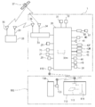
도 2는 제어 블록도이다.
도 3은 자율 주행 작업 차량과 수반 주행 작업 차량에 의한 병행 작업시의 상태를 나타내는 도면이다.
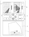
도 4는 원격 조작 장치의 표시 장치를 나타내는 도면이다.
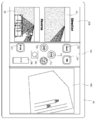
도 5는 표시 장치의 표시 화면을 전환한 상태를 나타내는 도면이다.
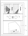
도 6은 주변 화상 영역에 하나의 화면을 표시한 상태를 나타내는 도면이다.
도 7은 주변 화상 영역의 전방 화면과 후방 화면을 상하 전환한 상태를 나타내는 도면이다.
도 8은 원격 조작 장치의 다른 표시 장치를 나타내는 도면이다.
도 9는 자동 주행 개시 버튼을 누른 후의 제2 조작 화면을 나타내는 도면이다.
도 10은 주행 속도 변경 버튼을 누른 후의 제2 조작 화면을 나타내는 도면이다.
도 11은 엔진 회전수 변경 버튼을 누른 후의 제2 조작 화면을 나타내는 도면이다.
도 12는 작업기 높이 변경 버튼을 누른 후의 제2 조작 화면을 나타내는 도면이다.1 is a schematic side view for operating an autonomous driving work vehicle with a remote control device.
2 is a control block diagram.
It is a figure which shows the state at the time of a parallel operation by an autonomous traveling work vehicle and accompanying traveling work vehicle.
4 is a view showing a display device of a remote control device.
5 is a view showing a state in which the display screen of the display device is switched.
6 is a view showing a state in which one screen is displayed in the surrounding image area.
7 is a view showing a state in which the front screen and the rear screen of the surrounding image area are switched up and down.
8 is a view showing another display device of the remote control device.
It is a figure which shows the 2nd operation screen after pushing the automatic driving start button.
10 is a view showing a second operation screen after pressing the travel speed change button.
It is a figure which shows the 2nd operation screen after pushing the engine speed change button.
It is a figure which shows the 2nd operation screen after pressing the work machine height change button.
무인으로 자동 주행 가능한 자율 주행 작업 차량(1) 및 이 자율 주행 작업 차량(1)에 수반하여 오퍼레이터가 탑승하여 조향 조작하는 수반 주행 작업 차량(100)을 트랙터로 하고, 자율 주행 작업 차량(1) 및 수반 주행 작업 차량(100)에 장착되는 작업기로서 로터리 경운 장치(24)가 장착된 실시 형태에 대해 설명한다. 단, 작업 차량은 트랙터에 한정하는 것은 아니며 콤바인 등일 수 있고, 작업기는 로터리 경운 장치(24)에 한정하는 것은 아니며, 시비 파종기, 예초기, 약제 살포기, 소독기 또는 수확기 등일 수 있다.An autonomous
도 1 및 도 2에서, 자율 주행 작업 차량(1)이 되는 트랙터의 전체 구성에 대해 설명한다. 보닛(2) 내에 엔진(3)이 마련되고, 상기 보닛(2) 후부의 캐빈(11) 내에 대시 보드(14)가 마련되며, 대시 보드(14) 상에 조향 조작 수단이 되는 스티어링 핸들(4)이 마련되어 있다. 상기 스티어링 핸들(4)의 회동에 의해 조타 장치를 통하여 전륜(9·9)의 방향이 회동된다. 자율 주행 작업 차량(1)의 조타 방향은 조향 센서(20)에 의해 감지된다. 조향 센서(20)는 로터리 엔코더 등의 각도 센서로 이루어지고, 전륜(9)의 회동 기저부에 배치된다. 단, 조향 센서(20)의 감지 구성은 한정되는 것은 아니며 조타 방향이 인식되는 것이면 무방하며, 스티어링 핸들(4)의 회동을 감지하거나 파워 스티어링의 작동량을 감지할 수도 있다. 조향 센서(20)에 의해 얻어진 검출값은 제어 장치(30)에 입력된다. 제어 장치(30)는 CPU(중앙 연산 처리 장치), RAM 또는 ROM 등의 기억 장치(30m)나 인터페이스 등을 구비하고, 기억 장치(30m)에는 자율 주행 작업 차량(1)을 동작시키기 위한 프로그램이나 데이터 등이 기억된다.In FIG. 1 and FIG. 2, the overall structure of the tractor which becomes the autonomous
상기 스티어링 핸들(4)의 후방에 운전석(5)이 배치되고, 운전석(5)의 하방에 미션 케이스(6)가 배치된다. 미션 케이스(6)의 좌우 양측에 리어 액슬 케이스(8·8)가 연장되어 마련되며, 상기 리어 액슬 케이스(8·8)에는 차축을 개재하여 후륜(10·10)이 지지된다. 엔진(3)으로부터 동력은 미션 케이스(6) 내의 변속 장치(메인 변속 장치나 서브 변속 장치)에 의해 변속되고, 후륜(10·10)을 구동 가능하게 한다. 변속 장치는 예를 들면, 유압식 무단 변속 장치로 구성하고, 가변 용량형 유압 펌프의 가동 경사판을 모터 등의 변속 수단(44)에 의해 작동시켜 변속 가능하게 한다. 변속 수단(44)은 제어 장치(30)와 접속된다. 후륜(10)의 회전수는 차속 센서(27)에 의해 감지되고 주행 속도로서 제어 장치(30)에 입력된다. 단, 차속의 감지 방법이나 차속 센서(27)의 배치 위치가 한정되는 것은 아니다.The driver's seat 5 is disposed at the rear of the steering handle 4, and the mission case 6 is disposed under the driver's seat 5. Rear
미션 케이스(6) 내에는 PTO 클러치나 PTO 변속 장치가 수납되며, PTO 클러치는 PTO 단속(斷續) 수단(45)에 의해 단절 및 접속되고, PTO 단속 수단(45)은 제어 장치(30)와 접속되며 PTO축으로 동력의 공급 및 단절을 제어 가능하게 한다.The PTO clutch or the PTO transmission is housed in the mission case 6, the PTO clutch is disconnected and connected by the PTO control means 45, and the PTO control means 45 communicates with the
상기 엔진(3)을 지지하는 프론트 프레임(13)에는 프론트 엑슬 케이스(7)가 지지되고, 상기 프론트 엑슬 케이스(7)의 양측에 전륜(9·9)이 지지되며, 상기 미션 케이스(6)로부터 동력이 전륜(9·9)에 전달 가능하게 구성된다. 상기 전륜(9·9)은 조타륜으로 되어 있으며, 스티어링 핸들(4)의 회동 조작에 의해 회동 가능함과 함께, 조타 장치의 구동 수단이 되는 파워 스티어링 실린더로 이루어지는 조타 액츄에이터(40)에 의해 전륜(9·9)이 좌우 조타 회동 가능하게 되어 있다. 조타 액츄에이터(40)는 제어 장치(30)와 접속되며, 자동 주행 수단에 의해 제어되어 구동된다.A
제어 장치(30)에는 엔진 회전 제어 수단이 되는 엔진 컨트롤러(60)가 접속되고, 엔진 컨트롤러(60)에는 엔진 회전수 센서(61), 수온 센서 또는 유압 센서 등이 접속되며, 엔진 상태를 감지할 수 있다. 엔진 컨트롤러(60)에서는 설정 회전수와 실제 회전수로부터 부하를 검출하여 과부하가 되지 않게 제어함과 함께, 후술하는 원격 조작 장치(112)에 엔진(3)의 상태를 송신하여 표시 장치(113)에서 표시할 수 있다.An
또한, 스텝 하방에 배치한 연료 탱크(15)에는 연료의 액면을 감지하는 레벨 센서(29)가 배치되고 제어 장치(30)와 접속되며, 자율 주행 작업 차량(1)의 대시 보드에 마련되는 표시 수단(49)에는 연료의 잔량을 표시하는 연료계가 마련되며 제어 장치(30)와 접속된다. 그리고, 제어 장치(30)로부터 원격 조작 장치(112)에 연료 잔량에 관한 정보가 송신되고, 원격 조작 장치(112)의 표시 장치(113)에 연료 잔량과 작업 가능 시간이 표시 가능하게 된다.In addition, a
상기 대시 보드(14) 상에는 엔진의 회전계, 연료계, 유압 등 이상을 나타내는 모니터 또는 설정값 등을 표시하는 표시 수단(49)이 배치된다.On the
또한, 트랙터 기체 후방에 작업기 장착 장치(23)를 개재하여 작업기로서 로터리 경운 장치(24)가 승강 가능하게 설치되어 있다. 상기 미션 케이스(6) 상에 승강 실린더(26)가 마련되고, 상기 승강 실린더(26)를 신축시킴으로써 작업기 장착 장치(23)를 구성하는 승강 아암을 회동시켜 로터리 경운 장치(24)를 승강할 수 있게 하고 있다. 승강 실린더(26)는 승강 액츄에이터(25)의 작동에 의해 신축되며, 승강 액츄에이터(25)는 제어 장치(30)와 접속된다.In addition, the
제어 장치(30)에는 위성 측위 시스템을 구성하는 이동 통신기(33)가 접속된다. 이동 통신기(33)에는 이동 GPS 안테나(34)와 데이터 수신 안테나(38)가 접속되고, 이동 GPS 안테나(34)와 데이터 수신 안테나(38)는 상기 캐빈(11) 상에 마련된다. 상기 이동 통신기(33)에는 위치 산출 수단을 구비하여 위도와 경도를 제어 장치(30)에 송신해, 현재 위치를 파악할 수 있도록 하고 있다. 한편, GPS(미국) 외에도 준천정 위성(일본)이나 글로나스 위성(러시아) 등의 위성 측위 시스템(GNSS)을 이용함으로써 정밀도가 높은 측위가 가능하나, 본 실시 형태에서는 GPS를 이용하여 설명한다.A
자율 주행 작업 차량(1)은 기체의 자세 변화 정보를 얻기 위한 자이로 센서(31) 및 진행 방향을 감지하기 위한 방위 센서(32)를 구비하고, 제어 장치(30)와 접속되어 있다. 단, GPS의 위치 계측으로부터 진행 방향을 산출할 수 있으므로, 방위 센서(32)를 생략할 수 있다.The autonomous
자이로 센서(31)는 자율 주행 작업 차량(1)의 기체 전후 방향의 경사(피치)의 각속도, 기체 좌우 방향의 경사(roll)의 각속도 및 선회(yaw)의 각속도를 검출하는 것이다. 상기 3개의 각속도를 적분 계산함으로써, 자율 주행 작업 차량(1)의 기체의 전후 방향 및 좌우 방향에 대한 경사 각도 및 선회 각도를 구할 수 있다. 자이로 센서(31)의 구체적인 예로서는, 기계식 자이로 센서, 광학식 자이로 센서, 유체식 자이로 센서, 진동식 자이로 센서 등을 들 수 있다. 자이로 센서(31)는 제어 장치(30)에 접속되고, 상기 3개의 각속도와 관련된 정보를 제어 장치(30)에 입력한다.The
방위 센서(32)는 자율 주행 작업 차량(1)의 방향(진행 방향)을 검출한다. 방위 센서(32)의 구체적인 예로는 자기(磁氣) 방위 센서 등을 들 수 있다. 방위 센서(32)는 제어 장치(30)에 접속되며, 기체의 방향과 관련된 정보를 제어 장치(30)에 입력한다.The
이와 같이 하여, 제어 장치(30)는 상기 자이로 센서(31), 방위 센서(32)로부터 취득한 신호를 자세·방위 연산 수단에 의해 연산하고, 자율 주행 작업 차량(1)의 자세(향하는 방향, 기체 전후 방향 및 기체 좌우 방향의 경사, 선회 방향)를 구한다.In this way, the
다음으로, 자율 주행 작업 차량(1)의 위치 정보를 GPS(global positioning system)를 이용하여 취득하는 방법에 대해 설명한다.Next, a method of acquiring the position information of the autonomous
GPS는 원래, 항공기·선박 등의 항법 지원용으로 개발된 시스템으로서, 상공 약 2만 킬로미터를 주회하는 24개의 GPS 위성(6개의 궤도면에 4개씩 배치), GPS 위성의 추적과 관제를 실시하는 관제국 및 측위를 하기 위한 이용자의 통신기로 구성된다.GPS is a system originally developed for navigation support for aircraft, ships, etc., and includes 24 GPS satellites (4 in 6 orbital planes) circulating about 20,000 kilometers in the air, and GPS satellite tracking and control. It consists of a user's communicator for empire and positioning.
GPS를 이용한 측위 방법으로서는, 단독 측위, 상대 측위, DGPS(Differential GPS) 측위, RTK(Real-Time Kinematic)-GPS 측위 등 여러 방법을 들 수 있으며, 이들 중 어느 방법을 사용해도 무방하나, 본 실시 형태에서는 측정 정밀도가 높은 RTK-GPS 측위 방식을 채용하고, 이 방법에 대해 도 1 및 도 2에 의해 설명한다.As the positioning method using GPS, there are various methods such as single positioning, relative positioning, DGPS (Differential GPS) positioning, and RTK (Real-Time Kinematic)-GPS positioning. Any of these methods may be used, but this implementation In the form, the RTK-GPS positioning method with high measurement precision is employed, and this method will be described with reference to FIGS. 1 and 2.
RTK-GPS 측위는 위치가 알고 있는 기준국과 위치를 구하려는 이동국에서 동시에 GPS 관측을 하여, 기준국에서 관측한 데이터를 무선 등의 방법으로 이동국에 실시간으로 송신하여, 기준국의 위치 성과에 기초하여 이동국의 위치를 실시간으로 구하는 방법이다.RTK-GPS positioning performs GPS observation at the same time by a reference station that the location knows and a mobile station that wants to find the location, and transmits the data observed by the reference station to the mobile station in real time by wireless or the like, based on the location performance of the reference station. This is a method for obtaining the location of a mobile station in real time.
본 실시 형태에서는, 자율 주행 작업 차량(1)에 이동국이 되는 이동 통신기(33), 이동 GPS 안테나(34) 및 데이터 수신 안테나(38)가 배치되고, 기준국이 되는 고정 통신기(35), 고정 GPS 안테나(36) 및 데이터 송신 안테나(39)가 포장(圃場)의 작업의 방해가 되지 않는 소정 위치에 배치된다. 본 실시 형태의 RTK-GPS 측위는 기준국 및 이동국의 양방에서 위상의 측정(상대 측위)을 하고, 기준국의 고정 통신기(35)에서 측위한 데이터를 데이터 송신 안테나(39)로부터 데이터 수신 안테나(38)에 송신한다.In the present embodiment, the
자율 주행 작업 차량(1)에 배치된 이동 GPS 안테나(34)는 GPS 위성(37·37···)으로부터 신호를 수신한다. 이 신호는 이동 통신기(33)에 송신되어 측위된다. 그리고, 동시에 기준국이 되는 고정 GPS 안테나(36)에서 GPS 위성(37·37···)으로부터 신호를 수신하여, 고정 통신기(35)에서 측위해 이동 통신기(33)로 송신하고, 관측된 데이터를 해석하여 이동국의 위치를 결정한다. 이와 같이 하여 얻어진 위치 정보는 제어 장치(30)에 송신된다.The
이와 같이 하여, 자율 주행 작업 차량(1)의 제어 장치(30)는 자동 주행시키는 자동 주행 수단을 구비하고, 자동 주행 수단은 GPS 위성(37·37···)으로부터 송신되는 전파를 수신하여 이동 통신기(33)에서 설정 시간 간격으로 기체의 위치 정보를 구하고, 자이로 센서(31) 및 방위 센서(32)로부터 기체의 변위 정보 및 방위 정보를 구하고, 이들 위치 정보, 변위 정보 및 방위 정보에 기초하여 기체가 미리 설정한 설정 경로(R)에 따라 주행하도록, 조타 액츄에이터(40), 변속 수단(44), 승강 액츄에이터(25), PTO 단속 수단(45), 엔진 컨트롤러(60) 등을 제어하여 자동 주행하며 자동으로 작업할 수 있다. 한편, 작업 범위가 되는 포장(H)의 외주의 위치 정보도 주지의 방법에 의해 미리 설정되어, 기억 장치(30m)에 기억된다.In this way, the
또한, 자율 주행 작업 차량(1)에는 장애물 센서(41)가 배치되며 제어 장치(30)와 접속되고, 장애물에 닿지 않게 된다. 예를 들면, 장애물 센서(41)는 레이저 센서나 초음파 센서로 구성되며 기체의 전부, 측부 또는 후부에 배치되어 제어 장치(30)와 접속되고, 기체의 전방, 측방 또는 후방에 장애물이 있는지 어떤지를 검출하여, 장애물이 설정 거리 이내로 가까워지면 주행을 정지시키도록 제어한다.In addition, an
또한, 자율 주행 작업 차량(1)에는 전방을 촬영하는 카메라(42F), 후방의 작업기 또는 작업 후 상태를 촬영하는 카메라(42R)가 탑재되고, 제어 장치(30)와 접속된다. 카메라(42F·42R)는, 본 실시 형태에서 캐빈(11)의 루프의 전부 위와 후부 위에 배치하고 있지만 배치 위치는 한정하는 것은 아니며, 캐빈(11) 내의 전부 위와 후부 위나, 하나의 카메라(42)를 기체 중심에 배치하여 연직축을 중심으로 회전시켜 주위를 촬영할 수도 있고, 복수의 카메라(42)를 기체의 네 모서리에 배치하여 기체 주위를 촬영하는 구성일 수도 있다. 카메라(42F·42R)로 촬영된 영상은 수반 주행 작업 차량(100)에 구비된 원격 조작 장치(112)의 표시 장치(113)에 표시되며, 그 화면에 대해서는 후술한다.In addition, the autonomous
원격 조작 장치(112)는 상기 자율 주행 작업 차량(1)의 주행 경로(R)를 설정하거나, 자율 주행 작업 차량(1)을 원격 조작하거나, 자율 주행 작업 차량(1)의 주행 상태나 작업기의 작동 상태를 감시하거나 또는 작업 데이터를 기억하며, 제어 장치(CPU나 메모리)(119), 통신 장치(111) 또는 표시 장치(113) 등을 구비한다.The
유인(有人) 주행 차량이 되는 수반 주행 작업 차량(100)은 오퍼레이터가 승차하여 운전 조작함과 함께, 수반 주행 작업 차량(100)에 원격 조작 장치(112)를 탑재하여 자율 주행 작업 차량(1)을 조작 가능하다. 수반 주행 작업 차량(100)의 기본 구성은 자율 주행 작업 차량(1)과 거의 동일한 구성이므로 상세한 설명은 생략한다. 한편, 수반 주행 작업 차량(100)에는 GPS용 이동 통신기(33)나 이동 GPS 안테나(34)를 구비하는 구성으로 할 수도 있다.The accompanying traveling
원격 조작 장치(112)는 수반 주행 작업 차량(100) 및 자율 주행 작업 차량(1)의 대시 보드 등의 조작부에 착탈 가능하게 되어 있다. 원격 조작 장치(112)는 수반 주행 작업 차량(100)의 대시 보드에 장착한 상태에서 조작하는 것 및 수반 주행 작업 차량(100)의 밖으로 꺼내 휴대하여 조작하는 것 모두, 자율 주행 작업 차량(1)의 대시 보드에 장착하여 조작 가능하다. 원격 조작 장치(112)는 예를 들면, 노트형이나 타블렛형 퍼스널 컴퓨터로 구성할 수 있다. 본 실시 형태에서는 타블렛형 컴퓨터로 구성되어 있다.The
또한, 원격 조작 장치(112)와 자율 주행 작업 차량(1)은 무선으로 서로 통신 가능하게 구성되어 있으며, 자율 주행 작업 차량(1)과 원격 조작 장치(112)에는 통신하기 위한 통신 장치(110·111)가 각각 마련되어 있다. 또한, 원격 조작 장치(112)는 수반 주행 작업 차량(100)의 제어 장치(130)와 통신 장치(133·111)를 개재하여 통신 가능하게 한다. 통신 장치(111)는 원격 조작 장치(112)에 일체적으로 구성된다. 통신 수단은 예를 들면, WiFi 등의 무선 LAN으로 서로 통신 가능하게 구성된다. 원격 조작 장치(112)는 화면에 접촉함으로써 조작 가능한 터치 패널식 조작 화면으로 한 표시 장치(113)를 섀시 표면에 마련하고, 섀시 내에 통신 장치(111), CPU, 기억 장치 또는 배터리 등을 수납한다.In addition, the
이러한 구성에서, 도 3에 나타낸 바와 같은 포장(H)에서 설정 주행 경로(R)를 미리 설정하여 기억 장치(30m)에 기억시키고, 자율 주행 작업 차량(1)이 설정 주행 경로(R)를 따라 주행시킬 수 있다. 한편, 상기 포장(H)의 위치를 정하거나 위성 측위 시스템을 이용하여 주행하거나, 또는 주행 경로(R)를 설정하기 위해 지도 데이터(정보)가 참조되지만, 이 지도 데이터는 인터넷에 공개되어 있는 지도 데이터, 지도 메이커 등이 제공하고 있는 지도 데이터, 또는 자동차 내비게이션 지도 데이터 등이 이용된다.In this configuration, the set travel path R is previously set in the pavement H as shown in FIG. 3 and stored in the
그리고, 자율 주행 작업 차량(1)과 수반 주행 작업 차량(100)의 로터리 경운 장치의 작업폭을 일부 중복시켜, 수반 주행 작업 차량(100)이 자율 주행 작업 차량(1)의 기울기 후방을 나란히 주행하면서 작업을 한다. 단, 수반 주행 작업 차량(100)은 자율 주행 작업 차량(1)의 후방을 주행하며 다른 작업을 실시하는 작업 형태로 할 수도 있으며 작업 형태는 한정되지 않는다.In addition, while partially overlapping the working widths of the rotary tilling device of the autonomous traveling
상기 원격 조작 장치(112)의 표시 장치(113)에는 상기 카메라(42F·42R)에서 촬영한 영상, 자율 주행 작업 차량(1) 상태, 작업 상태 또는 GPS에 관한 정보를 통신 장치(110·111)를 개재하여 제어 장치(119)에 송신하고, 그 영상, 정보 또는 조작 화면 등을 표시할 수 있으며, 오퍼레이터는 자율 주행 작업 차량(1)을 감시하면서 원격 조작 장치(112)를 조작할 수 있다.The
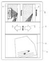
즉, 표시 장치(113)는 터치 조작식 화면으로서, 표시 방법, 표시 위치 또는 터치 조작에 대한 출력 등은 제어 장치(119)에 의해 제어된다. 표시 장치(113)의 표시 화면은 도 4에 나타낸 바와 같이, 세로(상하) 방향 또는 가로(좌우) 방향으로 복수의 영역으로 분할 가능하게 되어 있으며, 그 영역에는 적어도 상기 자율 주행 작업 차량(1)을 조작하는 원격 조작 영역(113A) 및 상기 자율 주행 작업 차량(1)에 장착된 카메라(42F·42R)에 의해 촬영한 영상을 표시하는 주변 화상 영역(113B)이 마련되어 있다.That is, the
원격 조작 영역(113A)은 자율 주행 작업 차량(1)의 주행, 조타 또는 작업기를 조작하기 위한 조작 부재(버튼)를 배치하는 화면이며, 본 실시 형태에서는 주행 속도 올림 버튼(201U), 주행 속도 내림 버튼(201D), 엔진 회전수 올림 버튼(202U), 엔진 회전수 내림 버튼(202D), 자동 주행 개시 버튼(203), 자동 주행 정지 버튼(204), 비상 정지 버튼(205), 인터넷 접속 버튼(206), 작업기 상승 버튼(207U), 작업기 하강 버튼(207D), PTO 온/오프 버튼(208)이 배치된다. 단, 상기 조작 버튼의 종류가 한정되는 것은 아니며, 브레이크 버튼, PTO 변속 버튼, 조타 버튼, 혼 버튼 또는 설정 버튼 등을 마련할 수도 있다. 또한, 조작하지 않는다면(불필요하다면) 그 버튼을 삭제할 수도 있다. 또한, 연료 잔량이나 엔진의 회전수 등을 표시하는 미터를 배치할 수도 있다. 그리고, 원격 조작 영역(113A) 내에서 이러한 버튼의 배치 위치나 형상 또한 한정되지 않으며, 임의의 형상으로 변경 및 선택하거나, 위치 변경할 수도 있다.The
상기 주행 속도 올림 버튼(201U)은 터치함으로써 변속 수단(44)을 작동시켜 1단계 증속시키는 것이며, 주행 속도 내림 버튼(201D)은 터치함으로써 변속 수단(44)을 작동시켜 1단계 감속시키는 것이다. 한편, 이 조작시에 변속단의 이름과 숫자를 팝업으로 표시하거나, 화면을 변속용 화면으로 전환하고 다른 화면은 닫도록 할 수 있다.The driving
상기 엔진 회전수 올림 버튼(202U)은 터치함으로써 액셀 액츄에이터를 작동시켜 연료 분사량을 증가시켜서 엔진 회전수를 증가시키는 것이며, 엔진 회전수 내림 버튼(202D)은 터치함으로써 액셀 액츄에이터를 작동시켜 연료 분사량을 감소시켜서 엔진 회전수를 감소시키는 것이다. 한편, 이 조작으로 엔진 회전수를 팝업으로 디지털 또는 아날로그로 표시하거나 화면을 엔진 회전수용 화면으로 전환할 수도 있다. 또한, 상기 주행 속도 올림 버튼(201U), 상기 주행 속도 내림 버튼(201D), 상기 엔진 회전수 올림 버튼(202U) 및 상기 엔진 회전수 내림 버튼(202D)은 계속 터치함으로써, 올림량 또는 내림량을 연속적으로 빠르게 증감시킬 수 있다.The engine speed up
자동 주행 개시 버튼(203)은 터치함으로써 미리 설정해 둔 주행 경로(R)를 자동 주행하면서 작업을 개시하고, 자동 주행 정지 버튼(204)을 터치함으로써 자동 주행 및 작업을 정지한다. 비상 정지 버튼(205)은 터치함으로써 엔진을 정지해 주행이나 작업을 정지하여 위험한 상태에 빠지는 것을 방지한다. 비상 정지 버튼(205)은 인식하기 쉽고 용이하게 조작할 수 있도록 화면 중앙에서 비교적 크고 눈에 띄는 색으로 표시된다. 인터넷 접속 버튼(206)은 터치함으로써 인터넷에 접속하여 미리 설정한 사이트에 들어가 표시한다.The automatic
작업기 상승 버튼(207U)은 터치함으로써 승강 액츄에이터(25)를 작동시켜 로터리 경운 장치(24)를 상승시킬 수 있고, 작업기 하강 버튼(207D)은 터치함으로써 승강 액츄에이터(25)를 작동시켜 로터리 경운 장치(24)를 하강시킨다. 한편, 이 조작으로 작업기(로터리 경운 장치(24))의 높이를 팝업으로 디지털 또는 아날로그로 표시하거나 화면을 작업기 승강용으로 전환할 수도 있다. PTO 온/오프 버튼(208)은 터치함으로써 PTO 단속 수단(45)을 작동시켜, PTO 접속 또는 PTO 단절로 전환한다. 이와 같이 하여, 화면을 보면서 손가락으로 터치하는 것만으로 떨어진 위치에서 용이하게 자율 주행 작업 차량(1)을 조작할 수 있다. 한편, 주행 속도, 엔진 회전수, 또는 작업기 높이 설정은 도시 생략한 다른 화면에서 설정된다.The work
상기 원격 조작 영역(113A)에 배치되는 복수의 버튼 중, 긴급시 즉시 응답을 요하는 비상 정지 버튼(205) 이외의 주행 속도 올림 버튼(201U), 주행 속도 내림 버튼(201D), 엔진 회전수 올림 버튼(202U), 엔진 회전수 내림 버튼(202D), 작업기 상승 버튼(207U), 작업기 하강 버튼(207D), 자동 주행 개시 버튼(203), 자동 주행 정지 버튼(204), 인터넷 접속 버튼(206) 및 PTO 온/오프 버튼(208)은 1회의 조작으로는 작동하지 않고, 여러 차례 조작해야 다음의 조작 화면으로 넘어가 작동할 수 있게 하여, 오조작이 생기지 않도록 구성할 수도 있다. 이 경우, 초기 화면은 도 8과 같은 화면이 된다.Among the plurality of buttons disposed in the
즉, 상기 원격 조작 영역(113A)의 대략 중앙에 배치되는 자동 주행 개시 버튼(203)은 미리 설정해 둔 주행 경로(R)를 자동 주행하면서 작업을 개시하기 위한 버튼이며, 자동 주행 개시 버튼(203)을 누르는 제1 조작(터치)을 포함하여, 제2 조작을 추가로 해야 자동 주행 제어 모드로 넘어가게 되어 있다. 제2 조작을 하면 자동 주행 제어 모드로 이행하여, 제어 장치(30)에 의해 자율 주행 작업 차량(1)의 자동 주행 제어가 이루어진다.That is, the automatic
제2 조작으로서는, 자동 주행 개시 버튼(203)을 누르는 제1 조작이 이루어지면, 다른 확인 화면으로 전환되고, 확인 화면에서 한번 더 조작하도록 하여 다음 모드로 넘어가도록 한다. 예를 들면, 자동 주행 개시 버튼(203)을 누르면, 도 9에 나타낸 바와 같이 START 버튼(203A)과 CANCEL 버튼(203B)이 나타난다. 그리고, START 버튼(203A)을 한번 더 누름으로써 자동 주행 제어 모드로 넘어가도록 하는 것이다. 자동 주행 제어 모드로 넘어가면 원래의 도 8의 화면으로 돌아간다. 잘못 누른 경우에는 CANCEL 버튼(203B)을 누름으로써 원래의 도 8의 화면으로 돌아간다. 단, 제2 조작의 화면은 도 9의 표시에 한정되는 것은 아니며, 「예」, 「아니오」 등과 같이 속행(續行) 또는 취소를 선택하여 확인할 수 있는 것이면 무방하다.As the second operation, when the first operation of pressing the automatic
또한, 상기 제2 조작의 조작 방법은 다른 조작으로 치환할 수 있다. 즉, 제2 실시예로서 자동 주행 개시 버튼(201)을 길게 누르면, 자동 주행 제어 모드로 넘어가도록 하는 것이다. 제2 조작의 제3 실시예로서 자동 주행 개시 버튼(203)을 2회 연속해서 누르면, 자동 주행 제어 모드로 넘어가도록 할 수 있다. 제2 조작의 제4 실시예로서 자동 주행 개시 버튼(203)을 누르면(제1 조작) 자동 주행 개시 버튼(203)의 색이 변화되고, 한번 더 누르면(제2 조작) 자동 주행 제어 모드로 넘어가도록 할 수도 있다. 제2 조작의 제5 실시예로서 자동 주행 개시 버튼(203)을 누르면서(제1 조작) 슬라이드시키면(제2 조작) 자동 주행 제어 모드로 넘어가도록 할 수도 있다. 한편, 이 제2 조작을 하여 자동 주행 제어 모드로 넘어가면, 오퍼레이터가 인식하기 쉽게 「자동 주행 제어 모드로 전환되었습니다」와 같은 화면이 표시되도록 할 수도 있다. 또한, 제1 조작을 하면 전체 화면 표시로 전환되도록 제어할 수도 있다.In addition, the operation method of the said 2nd operation can be substituted by another operation. That is, as the second embodiment, when the automatic
상기와 같이, 표시 장치(113)에는 상기 자율 주행 작업 차량(1)에 의한 자동 주행 개시 버튼(203)이 표시되고, 상기 자동 주행 개시 버튼(203)의 제1 조작을 포함하여, 제2 조작을 추가로 해야만 자동 주행 제어 모드로 넘어가게 하였으므로, 의도치 않게 표시 장치(113)의 화면에 접촉하거나 조작 실수를 함으로써, 자동 주행 제어 모드로 넘어가 자율 주행 작업 차량(1)이 갑자기 주행을 개시하는 일이 없으며, 사고 등이 발생하는 것을 방지할 수 있다.As described above, the automatic
또한, 상기 자동 주행이 개시된 후, 상기 자동 주행 정지 버튼(204)은 자동 주행 정지 버튼(204)을 터치하는 제1 조작을 하면 다른 확인 화면으로 전환되고, 제2 조작을 하면 자동 주행 및 작업을 정지한다. 인터넷 접속 버튼(206)은 인터넷 접속 버튼(206)을 터치하는 제1 조작을 하면 다른 확인 화면으로 전환되고, 제2 조작을 하면 인터넷에 접속하여 미리 설정한 사이트로 들어가 표시한다. PTO 온/오프 버튼(208)은 PTO 온/오프 버튼(208)을 터치하는 제1 조작을 하면 다른 확인 화면으로 전환되고, 제2 조작을 하면 PTO 단속 수단(45)을 작동시켜 PTO 접속하며, 또는 PTO 접속 상태에서 PTO 온/오프 버튼(208)을 터치하는 제1 조작을 하면 다른 확인 화면으로 전환되고, 제2 조작을 하면 PTO 단절로 전환된다.In addition, after the automatic driving is started, the automatic
상기 자동 주행 정지 버튼(204), 인터넷 접속 버튼(206) 또는 PTO 온/오프 버튼(208)도 상기 자동 주행 개시 버튼(203)의 조작과 마찬가지로, 제1 조작을 하면 다른 확인 화면(예, 아니오의 양자 선택 화면)으로 전환되는 대신, 제2 실시예∼제5 실시예와 같은 제2 조작을 해야 다음 모드로 넘어가도록 제어할 수도 있다.The automatic
상기 자동 주행이 개시된 후, 원격 조작 영역(113A)에 배치되는 다른 버튼의 조작에 대해 설명한다.After the above-described automatic driving is started, operation of another button disposed in the
상기 주행 속도 올림 버튼(201U) 및 주행 속도 내림 버튼(201D)은 도 8에 나타낸 바와 같이, 하나의 주행 속도 변경 버튼(201)으로 하고, 그 주행 속도 변경 버튼(201)을 터치하는 제1 조작을 하면 다른 확인 화면으로 전환되고, 제2 조작을 하면 변속 수단(44)을 작동시켜 1단계 변속시키는 것이다. 주행 속도 변경 버튼(201)을 터치하는 제1 조작을 하면, 본 실시 형태에서는, 도 10에 나타내는 증가 또는 감소를 조작하는 변경 확인 화면으로 바뀌고, 제2 조작을 하기 위한 제2 차속 변경 버튼으로서의 주행 속도 올림 버튼(201U)과 주행 속도 내림 버튼(201D)이 표시되도록 하고 있다. 주행 속도 올림 버튼(201U)을 터치함으로써 변속 수단(44)을 작동시켜 1단계 증속시키고, 주행 속도 내림 버튼(201D)을 터치함으로써 변속 수단(44)을 작동시켜 1단계 감속시킨다. 한편, 제1 조작으로 전체 화면 표시로 전환되고, 제2 조작시 변속단의 이름과 숫자를 팝업으로 표시하거나 화면을 변속용 화면으로 전환할 수도 있다.The driving
상기 엔진 회전수 올림 버튼(202U) 및 엔진 회전수 내림 버튼(202D)은, 도 8에 나타낸 바와 같이 하나의 엔진 회전수 변경 버튼(202)으로 하고, 그 엔진 회전수 변경 버튼(202)을 터치하는 제1 조작을 하면 다른 확인 화면으로 바뀌고, 제2 조작을 하면 액셀 액츄에이터를 작동시켜 연료 분사량을 변경한다. 엔진 회전수 변경 버튼(202)을 터치하는 제1 조작을 하면, 본 실시 형태에서는, 도 11에 나타내는 증가 또는 감소를 조작하는 변경 확인 화면으로 바뀌고, 제2 조작을 하기 위한 제2 엔진 회전수 변경 버튼이 되는 엔진 회전수 올림 버튼(202U)과 엔진 회전수 내림 버튼(202D)이 표시된다. 엔진 회전수 올림 버튼(202U)을 터치함으로써 액셀 액츄에이터를 작동시켜 연료 분사량을 증가시켜서 엔진 회전수를 증가시키고, 엔진 회전수 내림 버튼(202D)을 터치함으로써 액셀 액츄에이터를 작동시켜 연료 분사량을 감소시켜서 엔진 회전수를 감소시킨다. 한편, 제1 조작으로 전체 화면 표시로 전환되고, 제2 조작시 엔진 회전수를 팝업으로 디지털 또는 아날로그로 표시하거나 화면을 엔진 회전수용 화면으로 전환할 수도 있다. 또한, 상기 주행 속도 올림 버튼(201U), 상기 주행 속도 내림 버튼(201D), 상기 엔진 회전수 올림 버튼(202U) 및 상기 엔진 회전수 내림 버튼(202D)은 계속 터치함으로써, 올림량 또는 내림량을 빠르게 조절할 수 있다.The engine speed up
상기 작업기 상승 버튼(207U), 작업기 하강 버튼(207D)은 도 8에 나타낸 바와 같이, 하나의 작업기 높이 변경 버튼(207)으로 하고, 상기 작업기 높이 변경 버튼(207)을 터치하는 제1 조작을 하면 다른 확인 화면으로 전환되고, 제2 조작을 하면 승강 액츄에이터(25)를 작동시켜 로터리 경운 장치(24)를 승강시킨다. 작업기 높이 변경 버튼(207)을 터치하는 제1 조작을 하면, 본 실시 형태에서는 도 12에 나타내는 증가 또는 감소를 조작하는 변경 확인 화면으로 전환되고, 제2 조작을 하기 위한 제2 작업기 높이 변경 버튼이 되는 작업기 상승 버튼(207U)과 작업기 하강 버튼(207D)이 표시된다. 작업기 상승 버튼(207U)을 터치함으로써 승강 액츄에이터(25)를 작동시켜 로터리 경운 장치(24)를 상승시킬 수 있고, 작업기 하강 버튼(207D)을 터치함으로써 승강 액츄에이터(25)를 작동시켜 로터리 경운 장치(24)를 하강시킨다. 한편, 제1 조작으로 전체 화면 표시로 전환되고, 제2 조작시에 작업기(로터리 경운 장치(24))의 높이를 팝업으로 디지털 또는 아날로그로 표시하거나 화면을 작업기 승강용으로 전환할 수도 있다.8, the work
상기 주변 화상 영역(113B)은 카메라(42F)로 촬영한 기체 전방의 영상을 표시하는 전방 화면(210)과 카메라(42R)로 촬영한 기체 후방의 영상을 표시하는 후방 화면(211)으로 이루어지며, 주변 화상 영역(113B)에서의 상하 방향(세로 방향)에 배치하여 2개 표시로 되어 있다. 상기 후측의 카메라(42R)로 촬영하는 영상은, 트랙터와 작업기 사이의 장착 부분을 촬영하는 것일 수도 있고, 작업기의 작동 상태를 촬영하는 것일 수도 있으며, 작업기로부터 후방의 작업 마무리 상태를 촬영하는 것일 수 있다. 이 촬영 방향을 변경하기 위해, 카메라(42F·42R)의 지지부에는 각도 변경 수단을 마련할 수 있다. 또한, 액츄에이터로 변경할 수 있도록 하여, 원격 조작 장치(112)로 조정할 수 있도록 구성할 수도 있다. 또한, 카메라(42)의 수는 한정되지 않으며, 3대 이상 배치하여 각각의 영상을 주변 화상 영역(113B)에서 표시되도록 할 수도 있다.The
상기 후방 화면(211)에 비춰지는 영상은 거울상(좌우 반대)이며, 오퍼레이터가 자율 주행 작업 차량(1)의 진행 방향과 동일한 방향으로 조작하고 있을 때 위화감이 생기지 않도록 하고 있다. 한편, 전환 수단을 마련하여, 오퍼레이터가 수반 주행 작업 차량(100)을 타지 않고, 자율 주행 작업 차량(1)의 전방에서 대향하여 감시·조작하는 경우에는, 전방 화면(210)을 거울상, 후방 화면(211)을 실제상으로 할 수도 있다.The image projected on the
또한, 주변 화상 영역(113B)에서, 전방 화면(210)과 후방 화면(211)의 2개를 표시시키고 있으며, 자율 주행 작업 차량(1)이 자율 주행(자동 주행)하고 있을 때, 전후의 진행 방향을 변경하는 경우, 전방 화면(210)과 후방 화면(211)의 상하 표시 배치를 교체하도록 하고 있다. 예를 들면, 전진하고 있을 때에는 도 4에 나타낸 바와 같이, 상측에 전방 화면(210), 하측에 후방 화면(211)을 배치하고, 전진에서 후진으로 전환시에는 상측에 후방 화면(211), 하측에 전방 화면(210)을 표시하는 것이다.Further, in the
이 표시 전환은 실제로 진행 방향을 변경하기 약간 전에 표시가 전환된다. 즉, 제어 장치(30)의 기억 장치(30m)에는 설정 주행 경로(R)가 기억되어 있고, 그 설정 주행 경로(R)에서 전진에서 후진, 또는 후진에서 전진으로 전후진 전환을 실시하는 타이밍이나 위치는 프로그램되어 있으므로, 진행 방향이 전후 완전히 교체되는 설정 시간 전에, 표시 장치(113)의 화면이 예정 진행 방향에 맞추어 전환된다. 구체적으로는, 전후진 전환 명령을 발하는 설정 시간 전에(또는 전후진 전환 위치의 설정 거리 바로 앞에) 상하 표시 전환을 한다. 이 화면의 표시 전환은, 예를 들면, 자율 주행 작업 차량(1)의 전후진 전환 액츄에이터를 작동시키기 몇초 전에(또는 주행을 정지했을 때) 실시한다. 이와 같이 표시 장치(113)를 제어함에 따라 원격 조작 장치(112)를 조작하고 있는 오퍼레이터는 화면이 바뀜으로써 자율 주행 작업 차량(1)이 전후 진행 방향을 변경하는 것을 인식할 수 있으며, 만약, 진행 방향과 반대쪽에 장애물이 존재하는 것과 같은 경우에는, 진행하기 전에 자율 주행 작업 차량(1)을 정지하는 조작을 할 수 있어 사고를 미리 막을 수 있는 것이다.The display is actually switched slightly before changing the direction of travel. That is, the setting travel path R is stored in the
또한, 주변 화상 영역(113B)에서 2개를 표시하지 않고, 도 6에 나타낸 바와 같이 진행 방향만 표시하는 1개의 화면으로 할 수도 있다. 즉, 전진할 때에는 전방 화면(210)만 표시하고, 후진할 때에는 후방 화면(211)만 표시한다. 이 경우에도, 상기와 마찬가지로 전후진을 전환하기 약간 전에, 전방 화면(210)과 후방 화면(211)의 표시 전환을 한다. 단, 주변 화상 영역(113B)과 하나의 표시로 하는 경우, 통상적으로는 진행 방향만 표시하지만, 작업 후의 마무리 상태를 확인하고자 하는 경우가 있으므로, 후방 화면(211)으로 전환되도록 전환 버튼을 마련하거나, 더블 탭 등의 조작으로 화면을 전환하도록 할 수도 있다.In addition, two screens may not be displayed in the
상기 표시 장치(113)에는, 상기 원격 조작 영역(113A)과 상기 주변 화상 영역(113B)에 추가하여, 자율 주행 작업 차량(1)이 작업을 하는 포장의 맵이, 설정 주행 경로(R), 현재의 위치 또는 작업 완료 위치 등을 표시하는 작업 상태 표시 영역(113C)을 표시 가능하게 하고 있다. 작업 상태 표시 영역(113C)에서는 지도에 설정 주행 경로를 중첩시켜 이차원 표시, 삼차원 표시 또는 조감도로 표시할 수 있다. 또한, 이들을 전환할 수 있도록 전환 수단을 마련할 수도 있다.In the
또한, 주변 화상 영역(113B)과 작업 상태 표시 영역(113C)에 표시되는 화면은, 확대·축소 가능하게 구성할 수도 있다. 예를 들면, 주변 화상 영역(113B)의 후방 화면(211)에서 작업 후의 마무리를 좀 더 정밀하게 보고 싶은 경우에는, 화면을 손가락 두 개의 간격을 넓히는 핀치 아웃 조작으로 확대하여 확인하도록 할 수 있다. 또한, 작업 상태 표시 영역(113C)에서, 근처의 포장이나 주위의 두렁을 확인하고 싶은 경우 등에는 화면을 손가락 두 개의 간격을 좁히는 핀치 인 조작으로 축소하여 확인하도록 할 수 있다. 또한, 표시 화면을 드래그 조작하여 표시 위치(촬영 위치)를 이동할 수 있도록 할 수도 있다.In addition, the screen displayed on the
또한, 상기 원격 조작 영역(113A), 상기 주변 화상 영역(113B) 및 상기 작업 상태 표시 영역(113C)은, 좌우 또는 상하로 분할하여 동시에 표시 가능하게 이루어진다. 즉, 도 4의 실시 형태에서는, 좌측에 주변 화상 영역(113B), 중앙에 원격 조작 영역(113A), 우측에 작업 상태 표시 영역(113C)으로서 좌우로 화면을 3개 분할하여 동시에 표시하고, 복수의 표시 장치를 준비하지 않고 하나의 단말로 집약하여, 수반 주행 작업 차량(100)에 승차하여 조작할 때 설치 등이 용이하도록 할 수 있고, 자율 주행 작업 차량(1)의 위치 확인이나 속도 조절 등의 조작을 화면을 보면서 용이하게 할 수 있도록 하고 있다.In addition, the
또한, 중앙에 원격 조작 영역(113A)을 배치하고 양측에 주변 화상 영역(113B)과 작업 상태 표시 영역(113C)을 배치함에 따라, 자율 주행 작업 차량(1)의 비상 정지나 차속 조정 등 안전상 중요한 조작 버튼이 중앙에 배치되어 보기 쉽게 조작을 신속히 할 수 있다. 한편, 원격 조작 장치(112)를 세로로 길게 사용할 수 있다. 즉, 표시 장치(113)를 상하 3개로 분할할 수 있다. 또한, 이 분할된 상태에서, 상기 원격 조작 영역(113A), 상기 주변 화상 영역(113B) 및 상기 작업 상태 표시 영역(113C)중 어느 영역과 영역의 경계 부분을 드래그하여 평행 이동시킴으로써, 표시 영역을 확대 또는 축소하여 보고 싶은 화면을 확대하거나 필요하지 않은 화면을 축소할 수 있다.In addition, by arranging the
또한, 상기 원격 조작 영역(113A), 상기 주변 화상 영역(113B) 및 상기 작업 상태 표시 영역(113C)의 표시 위치는, 임의로 변경(교체) 가능하게 하여 사용자의 기호에 맞추거나 사용하기 쉽게할 수 있다. 즉, 원격 조작 영역(113A), 주변 화상 영역(113B) 및 작업 상태 표시 영역(113C)은 사용자의 기호나 편리한 사용 등을 고려하여 자유롭게 배치할 수 있다. 예를 들면, 화면상의 일부를 드래그하여, 도 4 내지 도 5에 나타낸 바와 같이, 원격 조작 영역(113A)을 중앙에서 좌측으로 이동하고, 주변 화상 영역(113B)을 우측으로 이동할 수 있도록 하는 것이다. 또한, 주변 화상 영역(113B)과 작업 상태 표시 영역(113C)을 좌측에 상하 2단으로 표시하고, 우측에 원격 조작 영역(113A)을 배치하여 표시할 수도 있다.In addition, the display positions of the
또한, 복수 표시 또는 전체 화면 표시의 선택도 임의로 변경할 수 있게 함으로써, 시인성이나 조작성을 향상시킬 수 있다. 즉, 원격 조작 영역(113A)만 전체 화면으로 표시하고, 버튼을 크게 표시시켜 조작 실수가 생기기 어렵게 하거나, 원격 조작 영역(113A)과 작업 상태 표시 영역(113C)의 2개를 표시하여, 작업 위치를 확인하면서 자율 주행 작업 차량(1)을 조작할 수 있다.In addition, visibility or operability can be improved by allowing the selection of multiple displays or full-screen displays to be arbitrarily changed. That is, only the
본 발명은, 자율 주행 가능한 건설 기계나 농용 작업차 등을 원격 조작 가능하게 하는 원격 조작 장치에 구비되는 표시 장치에 이용 가능하다.INDUSTRIAL APPLICABILITY The present invention can be used for a display device provided in a remote control device capable of remotely operating a construction machine or agricultural work vehicle capable of autonomous driving.
1: 자율 주행 작업 차량
30: 제어 장치
42F·42R: 카메라
110·111: 통신 장치
112: 원격 조작 장치
113: 표시 장치
113A: 원격 조작 영역
113B: 주변 화상 영역
113C: 작업 상태 표시 영역
119: 제어 장치
1: Autonomous driving work vehicle 30: Control unit
42F·42R:
112: remote control device 113: display device
113A:
113C: Job status display area 119: Control unit
Claims (7)
위성 측위 시스템을 이용하여, 설정한 주행 경로를 따라 상기 자율 주행 작업 차량에 의해 자동적으로 주행 및 작업을 가능하게 하는 제어부와,
상기 자율 주행 작업 차량에 장착한 카메라에 의해 촬영한 영상을 표시하는 표시부를 구비하고,
상기 표시부는, 상기 카메라로 촬영한 자율 주행 작업 차량의 진행 방향을 표시하는 한편으로, 상기 자율 주행 작업 차량의 진행 방향이 전환되기 전에, 상기 영상이 예정 진행 방향에 따라 전환되는 것을 특징으로 하는 원격 조작 시스템.A remote control system that operates an unmanned autonomous driving work vehicle,
Using a satellite positioning system, a control unit for automatically driving and working by the autonomous driving work vehicle along the set driving path,
It has a display unit for displaying the image taken by the camera mounted on the autonomous driving work vehicle,
On the other hand, the display unit, while displaying the direction of progress of the autonomous driving work vehicle photographed with the camera, before the direction of progress of the autonomous driving work vehicle is switched, the remote characterized in that the image is switched according to the predetermined progress direction Operation system.
상기 표시부는, 상기 자율 주행 작업 차량의 진행 방향이 전환되는 설정 시간 전 혹은 설정 거리 전에 전환을 실시하는 것을 특징으로 하는 원격 조작 시스템.According to claim 1,
The display unit, the remote control system, characterized in that to perform the switching before the set time or the set distance of the traveling direction of the autonomous driving work vehicle is switched.
상기 영상은, 상기 카메라로 촬영한 자율 주행 작업 차량의 전방의 영상을 표시하는 전방 화면과, 후방 화상을 표시하는 후방 화면을 포함하고,
상기 표시부는, 전방 화면과 후방 화면의 2개 표시와, 진행 방향만 표시하는 1개 표시로 전환할 수 있는 것을 특징으로 하는 원격 조작 시스템.According to claim 1,
The image includes a front screen displaying an image of the front of an autonomous driving work vehicle shot with the camera, and a rear screen displaying a rear image,
The display unit can be switched between two displays of the front screen and the rear screen, and one display that displays only the direction of travel.
상기 표시부가 전방 화면과 후방 화면의 2개 표시인 경우, 상기 작업 차량의 예정 진행 방향에 맞추어 전환되었을 때, 전방 화면과 후방 화면의 위치를 교체하는 것을 특징으로 하는 원격 조작 시스템.The method of claim 3,
If the display unit is two displays of the front screen and the rear screen, the remote control system, characterized in that when the switch to match the direction of travel of the work vehicle, the position of the front screen and the rear screen.
상기 표시부가 전방 화면과 후방 화면의 2개 표시인 경우, 상기 전방 화면과 상기 후방 화면은 거울상으로 되어 있는 것을 특징으로 하는 원격 조작 시스템.The method of claim 3,
When the display unit has two displays, a front screen and a rear screen, the remote control system is characterized in that the front screen and the rear screen are mirror images.
상기 원격 조작 장치는, 표시 장치를 구비하고,
상기 표시 장치는, 적어도 상기 자율 주행 작업 차량을 조작하는 원격 조작 영역을 구비하고,
상기 원격 조작 영역에는, 상기 자율 주행 작업 차량의 주행 제어를 설정하는 주행 설정부가 형성되고,
상기 주행 설정부를 길게 누른 경우, 상기 주행 설정부를 길게 누르지 않은 경우에 비해, 올림량 또는 내림량을 빠르게 할 수 있는 것을 특징으로 하는 원격 조작 장치.A remote control device capable of communicating with an autonomous driving work vehicle having a control device capable of automatically driving and working along a set driving route using a satellite positioning system,
The remote control device includes a display device,
The display device includes at least a remote operation area for operating the autonomous driving work vehicle,
A travel setting unit for setting travel control of the autonomous driving work vehicle is formed in the remote operation area,
When the driving setting unit is pressed for a long time, a remote control device characterized in that the amount of lifting or lowering can be made faster than when the driving setting unit is not long pressed.
상기 주행 설정부는, 상기 자율 주행 작업 차량의 엔진 회전수를 변경하는 엔진 회전수 조작부인 것을 특징으로 하는 원격 조작 장치.The method of claim 6,
The travel setting unit is a remote control device, characterized in that the engine speed control unit for changing the engine speed of the autonomous driving work vehicle.
Priority Applications (1)
| Application Number | Priority Date | Filing Date | Title |
|---|---|---|---|
| KR1020217015430A KR102394962B1 (en) | 2014-07-30 | 2015-07-02 | Remote control apparatus |
Applications Claiming Priority (8)
| Application Number | Priority Date | Filing Date | Title |
|---|---|---|---|
| JPJP-P-2014-155101 | 2014-07-30 | ||
| JP2014155099 | 2014-07-30 | ||
| JP2014155100 | 2014-07-30 | ||
| JPJP-P-2014-155099 | 2014-07-30 | ||
| JPJP-P-2014-155100 | 2014-07-30 | ||
| JP2014155101 | 2014-07-30 | ||
| KR1020177003945A KR102121554B1 (en) | 2014-07-30 | 2015-07-02 | Remote control apparatus |
| PCT/JP2015/069119 WO2016017367A1 (en) | 2014-07-30 | 2015-07-02 | Remote control apparatus |
Related Parent Applications (1)
| Application Number | Title | Priority Date | Filing Date |
|---|---|---|---|
| KR1020177003945A Division KR102121554B1 (en) | 2014-07-30 | 2015-07-02 | Remote control apparatus |
Related Child Applications (1)
| Application Number | Title | Priority Date | Filing Date |
|---|---|---|---|
| KR1020217015430A Division KR102394962B1 (en) | 2014-07-30 | 2015-07-02 | Remote control apparatus |
Publications (2)
| Publication Number | Publication Date |
|---|---|
| KR20200067947A true KR20200067947A (en) | 2020-06-12 |
| KR102257303B1 KR102257303B1 (en) | 2021-05-31 |
Family
ID=55217272
Family Applications (3)
| Application Number | Title | Priority Date | Filing Date |
|---|---|---|---|
| KR1020177003945A KR102121554B1 (en) | 2014-07-30 | 2015-07-02 | Remote control apparatus |
| KR1020217015430A KR102394962B1 (en) | 2014-07-30 | 2015-07-02 | Remote control apparatus |
| KR1020207016112A KR102257303B1 (en) | 2014-07-30 | 2015-07-02 | Remote control apparatus |
Family Applications Before (2)
| Application Number | Title | Priority Date | Filing Date |
|---|---|---|---|
| KR1020177003945A KR102121554B1 (en) | 2014-07-30 | 2015-07-02 | Remote control apparatus |
| KR1020217015430A KR102394962B1 (en) | 2014-07-30 | 2015-07-02 | Remote control apparatus |
Country Status (6)
| Country | Link |
|---|---|
| US (1) | US10324461B2 (en) |
| EP (1) | EP3175693B1 (en) |
| JP (1) | JP6131385B2 (en) |
| KR (3) | KR102121554B1 (en) |
| CN (2) | CN106572630B (en) |
| WO (1) | WO2016017367A1 (en) |
Cited By (1)
| Publication number | Priority date | Publication date | Assignee | Title |
|---|---|---|---|---|
| WO2023224432A1 (en) * | 2022-05-20 | 2023-11-23 | 주식회사 엘지유플러스 | Method for verifying control signal validity of autonomous vehicle in remote control driving state and device and system therefor |
Families Citing this family (79)
| Publication number | Priority date | Publication date | Assignee | Title |
|---|---|---|---|---|
| JP6437640B2 (en) * | 2015-05-07 | 2018-12-12 | ヤンマー株式会社 | Guidance control system for autonomous vehicles |
| JP6300112B2 (en) * | 2015-06-05 | 2018-03-28 | 株式会社ダイフク | Touch panel for manual operation of mechanical equipment |
| US10719289B2 (en) * | 2015-11-05 | 2020-07-21 | Topcon Positioning Systems, Inc. | Monitoring and control display system and method using multiple displays in a work environment |
| JP6656047B2 (en) * | 2016-03-29 | 2020-03-04 | ヤンマー株式会社 | Combine |
| KR102252840B1 (en) * | 2016-03-29 | 2021-05-17 | 얀마 파워 테크놀로지 가부시키가이샤 | combine |
| JP6480885B2 (en) * | 2016-03-29 | 2019-03-13 | ヤンマー株式会社 | Combine |
| JP6832660B2 (en) * | 2016-09-26 | 2021-02-24 | ヤンマーパワーテクノロジー株式会社 | Route generation system |
| KR101941187B1 (en) * | 2016-12-09 | 2019-04-15 | 한국생산기술연구원 | A remote control vehicle with spraying agricultural medicines device |
| JP6919548B2 (en) * | 2017-12-15 | 2021-08-18 | 株式会社タダノ | Work vehicle equipped with a remote control terminal and a remote control terminal |
| WO2018110707A1 (en) * | 2016-12-15 | 2018-06-21 | 株式会社タダノ | Remote operation terminal and work vehicle provided with remote operation terminal |
| JP6743676B2 (en) * | 2016-12-15 | 2020-08-19 | 株式会社タダノ | Remote control terminal |
| JP6698007B2 (en) * | 2016-12-20 | 2020-05-27 | 株式会社クボタ | Self-driving work vehicle |
| CN106612776B (en) * | 2016-12-29 | 2019-03-05 | 南京理工大学 | A kind of sowing and tumbrel |
| KR102443415B1 (en) * | 2017-01-20 | 2022-09-15 | 가부시끼 가이샤 구보다 | work car |
| JP6945303B2 (en) | 2017-01-20 | 2021-10-06 | 株式会社クボタ | Work vehicle and other vehicle monitoring system |
| JP6749256B2 (en) * | 2017-01-20 | 2020-09-02 | 株式会社クボタ | Work vehicle position measuring device |
| JP6739375B2 (en) * | 2017-03-03 | 2020-08-12 | ヤンマーパワーテクノロジー株式会社 | Wireless communication device |
| EP3396478B1 (en) * | 2017-04-28 | 2023-06-14 | Deere & Company | Apparatus, method and computer programme for controlling a machine |
| DE102017110159A1 (en) * | 2017-05-10 | 2018-11-15 | Claas Tractor Sas | Agricultural working machine |
| DE102017110109A1 (en) * | 2017-05-10 | 2018-11-15 | Claas Tractor Sas | Agricultural working machine |
| DE102017110106A1 (en) | 2017-05-10 | 2018-11-15 | Claas Tractor Sas | Agricultural working machine |
| DE202017103346U1 (en) * | 2017-06-02 | 2017-12-15 | Pöttinger Landtechnik Gmbh | Device for recording track data of an agricultural implement |
| JP6812306B2 (en) * | 2017-06-05 | 2021-01-13 | 株式会社クボタ | Work vehicle stop system and work vehicle equipped with it |
| WO2018227623A1 (en) * | 2017-06-16 | 2018-12-20 | 深圳市大疆创新科技有限公司 | Control method, aircraft system, and display terminal |
| JP7064693B2 (en) * | 2017-09-29 | 2022-05-11 | Toto株式会社 | Remote control system |
| CN107529041A (en) * | 2017-09-30 | 2017-12-29 | 江西洪都航空工业集团有限责任公司 | A kind of long-distance monitoring method for unmanned agricultural vehicle |
| JP6933545B2 (en) * | 2017-10-04 | 2021-09-08 | 株式会社小松製作所 | Work vehicle, control device, and work vehicle control method |
| JP6910927B2 (en) * | 2017-11-14 | 2021-07-28 | 株式会社クボタ | Field work support terminal, field work machine, and field work support program |
| KR102272510B1 (en) * | 2017-11-28 | 2021-07-05 | 엘에스엠트론 주식회사 | Remote control system for tractor |
| KR102037324B1 (en) | 2017-11-30 | 2019-10-28 | 엘지전자 주식회사 | Autonomous vehicle and method of controlling the same |
| JP6967958B2 (en) * | 2017-12-07 | 2021-11-17 | 株式会社クボタ | Field work support terminal, field work machine, and field work support program |
| JP7004162B2 (en) * | 2018-03-23 | 2022-01-21 | 株式会社豊田自動織機 | Remote control system for industrial vehicle, remote control device, industrial vehicle, remote control program for industrial vehicle, and remote control method for industrial vehicle |
| JP2020028224A (en) * | 2018-08-20 | 2020-02-27 | 株式会社クボタ | Field map creation system |
| USD872109S1 (en) | 2018-08-07 | 2020-01-07 | Caterpillar Inc. | Display screen or portion thereof with graphical user interface |
| CN115826585A (en) | 2018-08-08 | 2023-03-21 | 托罗公司 | Autonomous machine navigation and training using vision systems |
| DE102018119481A1 (en) * | 2018-08-10 | 2020-02-13 | Connaught Electronics Ltd. | Method for providing an image representation of at least part of an environment of a motor vehicle, computer program product and driver assistance system |
| JP7064066B2 (en) * | 2018-08-28 | 2022-05-10 | ヤンマーパワーテクノロジー株式会社 | Automatic driving system for work vehicles |
| JP7068969B2 (en) * | 2018-08-29 | 2022-05-17 | ヤンマーパワーテクノロジー株式会社 | Autonomous driving system |
| JP7175680B2 (en) * | 2018-08-31 | 2022-11-21 | 株式会社小松製作所 | Display control device, display control system, and display control method |
| JP7078259B2 (en) * | 2018-09-07 | 2022-05-31 | 松山株式会社 | Work support system for agricultural work machines |
| JP7078260B2 (en) * | 2018-09-07 | 2022-05-31 | 松山株式会社 | Work support system for agricultural work machines |
| WO2020056283A1 (en) | 2018-09-14 | 2020-03-19 | Agjunction Llc | Using non-real-time computers for agricultural guidance systems |
| CN109358625A (en) * | 2018-10-25 | 2019-02-19 | 丰疆智慧农业股份有限公司 | Automatic Pilot agricultural machinery and its dynamical system |
| US11772556B2 (en) * | 2018-10-31 | 2023-10-03 | Komatsu Ltd. | Display control system and display control method |
| US20210397765A1 (en) * | 2018-11-07 | 2021-12-23 | Honda Motor Co., Ltd. | Work area zone boundary demarcation apparatus of autonomously navigating work machine |
| JP7150593B2 (en) * | 2018-12-26 | 2022-10-11 | 株式会社クボタ | work vehicle |
| JP7054060B2 (en) * | 2018-12-27 | 2022-04-13 | 井関農機株式会社 | Work vehicle |
| DE102019202025B4 (en) * | 2019-02-15 | 2020-08-27 | Zf Friedrichshafen Ag | System and method for the safe operation of an automated vehicle |
| JP7256668B2 (en) * | 2019-03-29 | 2023-04-12 | 本田技研工業株式会社 | Control device, control method and program |
| WO2021021675A1 (en) * | 2019-07-26 | 2021-02-04 | Agjunction Llc | Using smart-phones and other hand-held mobile devices in precision agriculture |
| WO2021020405A1 (en) * | 2019-07-29 | 2021-02-04 | 住友建機株式会社 | Excavator |
| JP2021029147A (en) * | 2019-08-21 | 2021-03-01 | 株式会社テクノクラフト | Lawn surface information display system |
| DE102019125635A1 (en) * | 2019-09-24 | 2021-03-25 | Claas Tractor Sas | Agricultural work machine and method of starting |
| JP7305274B2 (en) * | 2019-09-25 | 2023-07-10 | 日立建機株式会社 | construction machinery |
| CN110673650B (en) * | 2019-11-21 | 2022-09-23 | 梅州市晟邦科技有限公司 | Unmanned aerial vehicle control method |
| JP7406360B2 (en) | 2019-12-06 | 2023-12-27 | 株式会社Subaru | image display system |
| KR102118293B1 (en) * | 2019-12-10 | 2020-06-02 | 주식회사 아진엑스텍 | Robot controlling method using portable device including touchscreen |
| JP7287262B2 (en) * | 2019-12-18 | 2023-06-06 | コベルコ建機株式会社 | Remote control system and remote control server |
| US20210191387A1 (en) * | 2019-12-23 | 2021-06-24 | Autonomous Solutions, Inc. | System and method for assisted teleoperations of vehicles |
| JP7301737B2 (en) * | 2019-12-27 | 2023-07-03 | 株式会社クボタ | work vehicle |
| US11567492B2 (en) * | 2020-01-17 | 2023-01-31 | Zimeno, Inc. | Vehicle control by a remote operator |
| JP2020072740A (en) * | 2020-02-04 | 2020-05-14 | ヤンマー株式会社 | Combine |
| US20210246636A1 (en) * | 2020-02-07 | 2021-08-12 | Caterpillar Inc. | System and Method of Autonomously Clearing a Windrow |
| CN113785091B (en) * | 2020-03-27 | 2023-10-24 | 住友重机械工业株式会社 | Construction machine, information management system, information terminal, and program |
| US11206544B2 (en) | 2020-04-13 | 2021-12-21 | Apple Inc. | Checkpoint identity verification on validation using mobile identification credential |
| US11853535B2 (en) | 2020-05-29 | 2023-12-26 | Apple Inc. | Sharing and using passes or accounts |
| US20210394785A1 (en) * | 2020-06-18 | 2021-12-23 | Caterpillar Paving Products Inc. | Remote manual and autonomous work machine control |
| US20220132828A1 (en) * | 2020-10-30 | 2022-05-05 | Deere & Company | Agricultural machine spraying mode field map visualization and control |
| JP7402145B2 (en) | 2020-11-13 | 2023-12-20 | 本田技研工業株式会社 | Remote control systems, mobile robots, and operating terminals |
| JP2022096512A (en) * | 2020-12-17 | 2022-06-29 | 井関農機株式会社 | Work vehicle |
| US20220299991A1 (en) * | 2021-03-22 | 2022-09-22 | Deere & Company | System and method for autonomous work machine approval |
| US20220306000A1 (en) * | 2021-03-24 | 2022-09-29 | Deere & Company | Work vehicle vision system with contextual task icons |
| US20220332285A1 (en) * | 2021-04-19 | 2022-10-20 | Apple Inc. | User interfaces for an electronic key |
| US20220350991A1 (en) * | 2021-04-30 | 2022-11-03 | Deere & Company | Vision guidance system using dynamic edge detection |
| CN113382294B (en) * | 2021-06-04 | 2023-05-12 | 广州小鹏汽车科技有限公司 | Picture display processing method and device of remote cockpit, cockpit and system |
| US11663309B2 (en) | 2021-06-06 | 2023-05-30 | Apple Inc. | Digital identification credential user interfaces |
| CN113359691B (en) * | 2021-07-08 | 2022-11-11 | 山东大学 | Remote image display device and method of non-road mobile equipment |
| JP2023150413A (en) * | 2022-03-31 | 2023-10-16 | ヤンマーホールディングス株式会社 | Operation support method, operation support system, and operation support program |
| JP2023156733A (en) * | 2022-04-13 | 2023-10-25 | ヤンマーホールディングス株式会社 | Work method, work vehicle and work system |
Citations (6)
| Publication number | Priority date | Publication date | Assignee | Title |
|---|---|---|---|---|
| JPH09271016A (en) * | 1996-03-29 | 1997-10-14 | Seibutsukei Tokutei Sangyo Gijutsu Kenkyu Suishin Kiko | Remote operation device for working vehicle |
| JP2001344017A (en) * | 2001-03-28 | 2001-12-14 | Hitachi Ltd | Automatic traveling machine |
| JP2005176741A (en) * | 2003-12-19 | 2005-07-07 | Yanmar Co Ltd | Agricultural working vehicle |
| JP2006221339A (en) * | 2005-02-09 | 2006-08-24 | Honda Motor Co Ltd | Vehicle control system |
| JP2007082523A (en) * | 2005-09-22 | 2007-04-05 | Yasutoshi Iwase | Tending robot for agricultural use |
| JP2011120539A (en) | 2009-12-11 | 2011-06-23 | Matsuyama Plow Mfg Co Ltd | Wireless control system of agricultural implement |
Family Cites Families (23)
| Publication number | Priority date | Publication date | Assignee | Title |
|---|---|---|---|---|
| US6044316A (en) * | 1994-12-30 | 2000-03-28 | Mullins; Donald B. | Method and apparatus for navigating a remotely guided brush cutting, chipping and clearing apparatus |
| KR19980068399A (en) * | 1997-02-19 | 1998-10-15 | 김영환 | Vehicle autonomous driving device and control method |
| JP3869792B2 (en) | 2000-11-17 | 2007-01-17 | 日立建機株式会社 | Display device and display control device for construction machine |
| JP2002182746A (en) * | 2000-12-19 | 2002-06-26 | Yanmar Agricult Equip Co Ltd | Work vehicle for agriculture |
| JP4295911B2 (en) * | 2000-12-19 | 2009-07-15 | ヤンマー農機株式会社 | Agricultural work vehicle |
| US7720580B2 (en) * | 2004-12-23 | 2010-05-18 | Donnelly Corporation | Object detection system for vehicle |
| US20060224280A1 (en) * | 2005-04-01 | 2006-10-05 | Flanigan Thomas C | Remote vehicle control systems |
| JP2007099261A (en) * | 2005-09-12 | 2007-04-19 | Aisin Aw Co Ltd | Parking assistance method and parking assistance device |
| US7826969B2 (en) * | 2006-12-21 | 2010-11-02 | Deere & Company | Determining position of a vehicle with reference to a landmark |
| JP4812613B2 (en) * | 2006-12-27 | 2011-11-09 | 日立建機株式会社 | Wheeled work machine |
| JP5145797B2 (en) * | 2007-07-04 | 2013-02-20 | パナソニック株式会社 | Video display device |
| JP4972610B2 (en) * | 2008-05-29 | 2012-07-11 | 株式会社クボタ | Accelerator control structure of work vehicle |
| US9188980B2 (en) * | 2008-09-11 | 2015-11-17 | Deere & Company | Vehicle with high integrity perception system |
| US9235214B2 (en) * | 2008-09-11 | 2016-01-12 | Deere & Company | Distributed knowledge base method for vehicular localization and work-site management |
| US8583313B2 (en) * | 2008-09-19 | 2013-11-12 | International Electronic Machines Corp. | Robotic vehicle for performing rail-related actions |
| JP5610870B2 (en) * | 2010-06-21 | 2014-10-22 | 三菱重工業株式会社 | Unmanned traveling vehicle guidance device and unmanned traveling vehicle guidance method |
| CN102529963A (en) * | 2010-12-14 | 2012-07-04 | 上海摩西海洋工程有限公司 | Computer-aided driving system |
| US20120185123A1 (en) * | 2011-01-19 | 2012-07-19 | Adil Ansari | System and method for vehicle path determination |
| US9288938B2 (en) * | 2012-06-01 | 2016-03-22 | Rowbot Systems Llc | Robotic platform and method for performing multiple functions in agricultural systems |
| JP6240384B2 (en) * | 2012-11-29 | 2017-11-29 | ヤンマー株式会社 | Autonomous traveling work system |
| JP5928402B2 (en) * | 2013-04-19 | 2016-06-01 | 株式会社ダイフク | Traveling vehicle control system |
| EP2884364B1 (en) * | 2013-12-12 | 2018-09-26 | Hexagon Technology Center GmbH | Autonomous gardening vehicle with camera |
| KR20200039817A (en) * | 2014-03-28 | 2020-04-16 | 얀마 가부시키가이샤 | Autonomous travelling service vehicle |
-
2015
- 2015-07-02 WO PCT/JP2015/069119 patent/WO2016017367A1/en active Application Filing
- 2015-07-02 US US15/329,798 patent/US10324461B2/en active Active
- 2015-07-02 EP EP15827436.5A patent/EP3175693B1/en active Active
- 2015-07-02 JP JP2016510543A patent/JP6131385B2/en active Active
- 2015-07-02 CN CN201580041953.5A patent/CN106572630B/en active Active
- 2015-07-02 KR KR1020177003945A patent/KR102121554B1/en active IP Right Grant
- 2015-07-02 KR KR1020217015430A patent/KR102394962B1/en active IP Right Grant
- 2015-07-02 KR KR1020207016112A patent/KR102257303B1/en active IP Right Grant
- 2015-07-02 CN CN202010309757.4A patent/CN111480407B/en active Active
Patent Citations (6)
| Publication number | Priority date | Publication date | Assignee | Title |
|---|---|---|---|---|
| JPH09271016A (en) * | 1996-03-29 | 1997-10-14 | Seibutsukei Tokutei Sangyo Gijutsu Kenkyu Suishin Kiko | Remote operation device for working vehicle |
| JP2001344017A (en) * | 2001-03-28 | 2001-12-14 | Hitachi Ltd | Automatic traveling machine |
| JP2005176741A (en) * | 2003-12-19 | 2005-07-07 | Yanmar Co Ltd | Agricultural working vehicle |
| JP2006221339A (en) * | 2005-02-09 | 2006-08-24 | Honda Motor Co Ltd | Vehicle control system |
| JP2007082523A (en) * | 2005-09-22 | 2007-04-05 | Yasutoshi Iwase | Tending robot for agricultural use |
| JP2011120539A (en) | 2009-12-11 | 2011-06-23 | Matsuyama Plow Mfg Co Ltd | Wireless control system of agricultural implement |
Cited By (1)
| Publication number | Priority date | Publication date | Assignee | Title |
|---|---|---|---|---|
| WO2023224432A1 (en) * | 2022-05-20 | 2023-11-23 | 주식회사 엘지유플러스 | Method for verifying control signal validity of autonomous vehicle in remote control driving state and device and system therefor |
Also Published As
| Publication number | Publication date |
|---|---|
| CN111480407B (en) | 2022-07-12 |
| JPWO2016017367A1 (en) | 2017-04-27 |
| EP3175693A4 (en) | 2017-08-09 |
| US10324461B2 (en) | 2019-06-18 |
| CN106572630B (en) | 2020-05-15 |
| KR20170037985A (en) | 2017-04-05 |
| KR102394962B1 (en) | 2022-05-04 |
| JP6131385B2 (en) | 2017-05-17 |
| CN111480407A (en) | 2020-08-04 |
| WO2016017367A1 (en) | 2016-02-04 |
| CN106572630A (en) | 2017-04-19 |
| EP3175693B1 (en) | 2022-08-31 |
| US20170248946A1 (en) | 2017-08-31 |
| KR102121554B1 (en) | 2020-06-10 |
| EP3175693A1 (en) | 2017-06-07 |
| KR102257303B1 (en) | 2021-05-31 |
| KR20210063448A (en) | 2021-06-01 |
Similar Documents
| Publication | Publication Date | Title |
|---|---|---|
| KR102121554B1 (en) | Remote control apparatus | |
| JP6267626B2 (en) | Travel route setting device | |
| JP6368964B2 (en) | Control device for work vehicle | |
| KR102192966B1 (en) | Operation terminal | |
| JP6339427B2 (en) | Parallel work system | |
| JP6267627B2 (en) | Operation terminal | |
| JP6253565B2 (en) | Operation terminal | |
| JP6267586B2 (en) | Display device | |
| JP6163460B2 (en) | Accompanying work system | |
| JP6078025B2 (en) | Parallel work system | |
| JP2015222499A (en) | Emergency stop system | |
| JP6297436B2 (en) | Parallel work system | |
| JP2015222500A (en) | Emergency stop system | |
| JP6258781B2 (en) | Emergency stop device | |
| JP2015222502A (en) | Emergency stop system | |
| JP2021074007A (en) | Travel route generating method and travel route generating system | |
| JP2018050632A (en) | Traveling route setting device | |
| JP6832996B2 (en) | Travel route generation method |
Legal Events
| Date | Code | Title | Description |
|---|---|---|---|
| A107 | Divisional application of patent | ||
| E902 | Notification of reason for refusal | ||
| E701 | Decision to grant or registration of patent right |